Hot Melt Electrospinning
Finnegan; Shane ; et al.
U.S. patent application number 16/624997 was filed with the patent office on 2020-07-23 for hot melt electrospinning. The applicant listed for this patent is Avectas Limited. Invention is credited to Shane Finnegan, Gillian Hendy, Michael Maguire.
| Application Number | 20200232121 16/624997 |
| Document ID | / |
| Family ID | 63407479 |
| Filed Date | 2020-07-23 |


View All Diagrams
| United States Patent Application | 20200232121 |
| Kind Code | A1 |
| Finnegan; Shane ; et al. | July 23, 2020 |
HOT MELT ELECTROSPINNING
Abstract
Systems, devices, and methods for electro spinning are provided. For example, a system includes a collector including load sensors attached thereto, the collector configured to receive an extruded polymer; and an electro spinning melt head assembly positioned above the collector and configured to extrude the polymer. The electro spinning melt head assembly and/or the collector is configured to move. The melt head assembly includes a syringe assembly and at least one heating element configured to supply heat to the syringe assembly. The syringe assembly includes: a syringe including a passage extending from a proximal end, the passage configured to receive the polymer, and a nozzle configured to allow polymer to pass therethrough.
| Inventors: | Finnegan; Shane; (Dublin, IE) ; Hendy; Gillian; (Dublin, IE) ; Maguire; Michael; (Dublin, IE) | ||||||||||
| Applicant: |
|
||||||||||
|---|---|---|---|---|---|---|---|---|---|---|---|
| Family ID: | 63407479 | ||||||||||
| Appl. No.: | 16/624997 | ||||||||||
| Filed: | June 22, 2018 | ||||||||||
| PCT Filed: | June 22, 2018 | ||||||||||
| PCT NO: | PCT/IB2018/000764 | ||||||||||
| 371 Date: | December 20, 2019 |
Related U.S. Patent Documents
| Application Number | Filing Date | Patent Number | ||
|---|---|---|---|---|
| 62524119 | Jun 23, 2017 | |||
| Current U.S. Class: | 1/1 |
| Current CPC Class: | D01D 5/0076 20130101; D01D 5/084 20130101; D01D 5/0023 20130101 |
| International Class: | D01D 5/00 20060101 D01D005/00; D01D 5/084 20060101 D01D005/084 |
Claims
1. A system, comprising: a collector including load sensors attached thereto, the collector configured to receive an extruded polymer; and an electrospinning melt head assembly positioned above the collector and configured to extrude the polymer, wherein the electrospinning melt head assembly and/or the collector is configured to move, the melt head assembly including a syringe assembly and at least one heating element configured to supply heat to the syringe assembly, the syringe assembly comprising: a syringe including a passage extending from a proximal end, the passage configured to receive the polymer, and a nozzle configured to allow polymer to pass therethrough.
2. The system of claim 1, the syringe assembly further comprising: a plunger sized and shaped to be slidably received within the passage such that distal motion of the plunger causes extrusion of the polymer; wherein the system further comprises a plunger drive system configured to supply a mechanical force to actuate the plunger.
3. The system of claim 2, further comprising: an imaging system configured to monitor extrusion of the polymer; and a probe configured to measure a strength of an electric field between the nozzle and the collector.
4. The system of claim 3, further comprising a control and processing system configured to receive signals from the plunger drive system, the imaging system, the load sensors, and the probe, and to control the position of the electrospinning melt head assembly, the force applied to the plunger, a voltage of the collector, and a rate of extrusion of the polymer.
5. The system of claim 4, wherein the rate of extrusion is controlled to follow a rectified sinusoidal profile.
6. The system of claim 4, wherein the rate of extrusion is between 0.1 gram/hour and 10 gram/hour.
7. The system of claim 6, wherein the rate of extrusion is 0.1 gram/hour, 0.2 gram/hour, 0.3 gram/hour, 0.4 gram/hour, 0.5 gram/hour, 0.6 gram/hour, 0.7 gram/hour, 0.8 gram/hour, 0.9 gram/hour, 1.0 gram/hour, 2.0 gram/hour, 3.0 gram/hour, 4.0 gram/hour, 5.0 gram/hour, 6.0 gram/hour, 7.0 gram/hour, 8.0 gram/hour, 9.0 gram/hour, or 10.0 gram/hour.
8. The system of claim 4, wherein the voltage of the collector is between 0 and 20 kV, 1 kV, 2 kV, 5 kV, 10 kV, 15 kV, 20 kV, 25 kV, 30 kV, or 40 kV.
9. The system of claim 4, further comprising a voltage source providing a maximum current to the collector of 0.01 mA, 0.1 mA, 0.18 mA, 0.2 mA, 0.3 mA, 0.6 mA, 1.0 mA, 10 mA, or 100 mA.
10. The system of claim 1, further comprising: a drive system including a pump configured to supply a pressure inside the syringe via a gas.
11. The system of claim 1, further including a support assembly that retains the electrospinning melt head assembly or the collector.
12. An electrospinning melt head assembly, comprising: a syringe assembly including, a nozzle, a plunger including at least one sealing element disposed on an outer surface thereof, a first passage extending from a first opening in a proximal end of the syringe assembly, the passage being sized and shaped to slidably receive the plunger such that the at least one sealing element on the plunger forms a seal with a wall that defines the first passage, a second opening in a distal end, the second opening being fluidly coupled to the first passage, the second opening being sized and shaped to releasably receive the a portion of the nozzle therein; at least one heating element configured to supply heat to the syringe assembly.
13. The assembly of claim 12, further comprising a heater assembly that retains the at least one heating element, the heater assembly having a second passage extending from a proximal end thereof, the second passage sized and shaped to receive the at least a portion syringe assembly.
14. The assembly of claim 13, wherein the at least one heating element encircles the second passage.
15. The assembly of claim 13, wherein the heating element is positioned within a lower half of the heater assembly.
16. The assembly of claim 13, further comprising an insulation sleeve, the insulation sleeve having a third passage configured to receive the syringe assembly and the at least one heating element.
17. A method comprising: applying power to a heating element to generate heat to transfer to a polymer and melt the polymer within a syringe; measuring a temperature associated with the polymer; applying a voltage to a collector to generate an electric field across a gap between the collector and a nozzle that is releasably coupled to the syringe; moving the nozzle and/or the collector to pass the nozzle over a portion of the collector at least one time; and applying force to a proximal end of a plunger that is slidably disposed within the syringe to force the plunger toward the nozzle, thereby forcing a portion of the polymer out of the nozzle and into the electric field such that it creates a polymer stream extending from the nozzle, wherein the polymer stream cools and forms fibers during travel from the nozzle to the collector.
18. The method of claim 17, further comprising adjusting a size of the gap with every pass of the nozzle over a given point on the collector.
19. The method of claim 17, further comprising moving the nozzle and/or collector based on an excursion profile to create small bends in the polymer stream.
20. The method of claim 0, wherein the excursion profile includes a rectified sinusoidal profile.
21. The method of claim 17, further comprising using load sensors to determine a rate of polymer extrusion from the nozzle.
22. The method of claim 17, further comprising using an imaging system in conjunction with machine vision software to determine a rate of polymer extrusion from the nozzle.
23. The method of claim 17, wherein air pressure creates the force at the proximal end of the plunger.
24. The method of claim 0, further comprising reducing the air pressure sufficiently to draw the plunger away from the nozzle to stop, or reduce, flow of polymer from the nozzle.
25. The method of claim 17, further comprising measuring a strength of the electric field.
26. The method of claim 25, further comprising adjusting the voltage of the collector based on the measured strength of the electric field.
27. The method of claim 25, further comprising adjusting a size of the gap between the nozzle and the collector based on the measure strength of the electric field.
28. A system comprising: a collector including load sensors attached thereto, the collector configured to receive an extruded polymer; an electrospinning melt head assembly positioned above the collector and configured to extrude the polymer, wherein the electrospinning melt head assembly and/or the collector is configured to move in at least one of X, Y, and Z directions, the melt head assembly including a syringe assembly and at least one heating element configured to supply heat to the syringe assembly, the syringe assembly comprising: a syringe including a passage extending from a proximal end, the passage being configured to receive the polymer, a nozzle configured to allow polymer to pass therethrough; a drive system configured to supply a pressure inside the syringe; an imaging system configured to monitor extrusion of the polymer; and a probe configured to measure a strength of an electric field between the nozzle and the collector.
29. The system of claim 28, further comprising a control and processing system configured to receive signals from the drive system, the imaging system, the load sensors, and the probe, and to control the position of the electrospinning melt head assembly, the pressure supplied to the syringe, a voltage of the collector, and a rate of extrusion of the polymer.
30. The system of claim 28, further including a support assembly that retains the electrospinning melt head assembly or the collector.
31. An electrospinning melt head assembly, comprising: a syringe assembly including a nozzle, a first passage extending from a first opening in a proximal end of the syringe assembly, a second opening in a distal end, the second opening being fluidly coupled to the first passage, the second opening being sized and shaped to releasably receive the a portion of the nozzle therein; at least one heating element configured to supply heat to the syringe assembly.
32. The assembly of claim 31, further comprising a heater assembly that retains the at least one heating element, the heater assembly including a second passage extending from a proximal end thereof, the second passage sized and shaped to receive the at least a portion syringe assembly.
33. The assembly of claim 32, wherein the at least one heating element encircles the second passage.
34. The assembly of claim 32, wherein the heating element is positioned within a lower half of the heater assembly.
35. The assembly of claim 32, further comprising an insulation sleeve, the insulation sleeve including a third passage configured to receive the syringe assembly and the at least one heating element.
36. (canceled)
Description
CROSS-REFERENCE TO RELATED APPLICATION
[0001] This application claims priority from U.S. Provisional Application No. 62/524,119 filed on Jun. 23, 2017, the disclosure of which is hereby expressly incorporated herein by reference in its entirety.
FIELD
[0002] The subject matter described herein relates to electrospinning technology that provides reliable fiber output and improved control.
BACKGROUND
[0003] Electrospinning can include a method of producing fibers that utilizes electrical potential to draw liquid polymer threads across a gap between a conductive source emitter and a conductive collector, or counter electrode. When a sufficiently high voltage is applied to a liquid droplet, the body of the liquid can become charged, and electrostatic repulsion can counteract surface tension and the droplet can be stretched from the emitter. At a critical point, as the droplet extends from the emitter toward the counter electrode, a stream of liquid can erupt from the droplet. The geometry of the extended droplet from which the stream erupts is known as a Taylor cone. If molecular cohesion of the liquid is sufficiently high, stream breakup can be avoided and a charged liquid jet can be formed. During travel from the emitter to the collector, the stream can dry. As the stream dries, and/or cools, the mode of current flow can change from ohmic to convective as charge migrates to the surface of the forming fiber. While traveling toward the collector, the stream can be moved by a "whipping" process to create small bends in the fiber, which can cause the fiber to thin and lengthen, until it is deposited onto the collector. The thinning and elongation as a result of the whipping process can lead to the formation of uniform fibers with nanometer scale diameters.
[0004] Electrospinning research has been focused towards the fabrication of nanofibers. The majority of this research involves the use of solution electrospinning and there has been less investigation into melt electrospinning since this method most commonly produces fibers larger than 1 .mu.m. In solution electrospinning, the jet can thin by an order of magnitude solely due to the evaporation of solvent. On the other hand, by using high melt viscosity (.eta..sub.melt) and non-conductive polymer melts (typically with electrical conductivity less than 10-10 S/m), the absence of a solvent greatly reduces surface charge density (.sigma..sub.q) and therefore dampens the bending instabilities. When the temperature of the electrified jet is below the glass transition temperature (T.sub.g) of the polymer, rapid solidification of the molten jet further suppresses whipping; since greater disturbance forces are required to overcome the surface tension. The initial region of the electrified molten jet has often a considerable volume and movement from the midline is reduced. The suppression of bending instabilities considerably reduces the degree of stretching the melt electrospinning jet encounters before it solidifies. With the additional lack of thinning from solvent evaporation, melt electrospinning has typically been characterized by larger diameter fibers than from solution.
[0005] Through careful process design, optimization and control, sub-micron fibers can be obtained in melt electrospinning. Similar to in melt extrusion systems, this can be accomplished by control of the extensional viscosity and solidification of the filament via the thermal environment. However since melt electrospinning is a further convoluted problem, electric field and charge transfer effects must be considered in addition to the heat transfer effects on momentum and mass conservation, viscoelastic properties, and, in some cases, in-flight crystallization. By making additional material modifications prior to processing, fiber diameters approaching true nanoscale magnitudes can be produced using polymer melts: rather than delivering the polymer in a solution, including additives to increase the electrical conductivity of the polymer melt is another strategy to increase the charge density on the melt jet, thereby inducing a greater degree of stretching on the jet during flight.
SUMMARY
[0006] The current subject matter can include an electrospinning melt assembly that monitors and controls a temperature of a polymer, reduces heat fluctuation in a polymer to achieving uniform melting of the polymer, measures deposited material during an experimental run using load sensors on the collector would allow the user to monitor the rate of extrusion, and uses a rectified sinusoidal excursion profile during extrusion can provide smoother linear excursions and hence better deposited fiber structures. In addition, the current subject matter can include active measurement and feedback of an electric field between an emitter and a collector of the electrospinning melt assembly from either current or charge sensors that can allow the applied voltage to be controlled, thereby allowing an electric field density to be maintained.
[0007] In an aspect, a system includes a collector including load sensors attached thereto, the collector configured to receive an extruded polymer; and an electrospinning melt head assembly positioned above the collector and configured to extrude the polymer. The electrospinning melt head assembly and the collector are configured to move relative to one another (e.g., the collector can move and the melt head assembly can be stationary, the melt head assembly can move and the collector can be stationary, or both the collector and the melt head assembly can move). The melt head assembly includes a syringe assembly and at least one heating element configured to supply heat to the syringe assembly. The syringe assembly includes: a syringe including a passage extending from a proximal end, the passage configured to receive the polymer, and a nozzle configured to allow polymer to pass therethrough.
[0008] One or more of the following features can be included in any feasible combination. For example, the syringe assembly can include a plunger sized and shaped to be slidably received within the passage such that distal motion of the plunger causes extrusion of the polymer. The system can further include a plunger drive system configured to supply a mechanical force to actuate the plunger. The system can include an imaging system configured to monitor extrusion of the polymer; and a probe configured to measure a strength of an electric field between the nozzle and the collector. The system can further include a control and processing system configured to receive signals from the plunger drive system, the imaging system, the load sensors, and the probe, and to control the position of the electrospinning melt head assembly, the force applied to the plunger, a voltage of the collector, and a rate of extrusion of the polymer.
[0009] The system can further include a plunger drive system configured to supply a pressure inside the syringe. The system can further include a support assembly that retains the electrospinning melt head assembly.
[0010] The rate of extrusion can be controlled to follow a rectified sinusoidal profile. In some implementations, the rate of extrusion is between 0.1 gram/hour and 10 gram/hour. For example, the rate of extrusion can be 0.1 gram/hour, 0.2 gram/hour, 0.3 gram/hour, 0.4 gram/hour, 0.5 gram/hour, 0.6 gram/hour, 0.7 gram/hour, 0.8 gram/hour, 0.9 gram/hour, 1.0 gram/hour, 2.0 gram/hour, 3.0 gram/hour, 4.0 gram/hour, 5.0 gram/hour, 6.0 gram/hour, 7.0 gram/hour, 8.0 gram/hour, 9.0 gram/hour, or 10.0 gram/hour. The voltage of the collector can be between 0 and 20 kV, 1 kV, 2 kV, 5 kV, 10 kV, 15 kV, 20 kV, 25 kV, 30 kV, or 40 kV. A voltage source can be included and can provide a maximum current to the collector of 0.01 mA, 0.1 mA, 0.18 mA, 0.2 mA, 0.3 mA, 0.6 mA, 1.0 mA, 10 mA, or 100 mA. The system can include a drive system, which can include a plunger or can be without a plunger and operate, e.g., utilizing gas. For example, the system can include a drive system including a pump configured to supply a pressure inside the syringe via a gas.
[0011] The melt head assembly and/or the collector can be configured to move in one or more of three directions, e.g., x, y, z directions. In some implementations, the melt head assembly and/or collector can move in more than the x, y, z directions. For example, the melt head assembly and/or collector can move in any specified coordinate system such as polar, spherical, or cylindrical coordinates. Further, in some implementations, the melt head assembly and/or collector can move in 2, 3, 4, 5, 6, 7, 8, 9, 10, 11, 12, and/or more directions. In some implementations, the x and y directions are separated by 90 degrees, and the z direction is separated by 90 degrees from a plane formed in the x and y directions. In some implementations, the collector moves such that the motion of the melt head assembly is relative to the collector. In some implementations, the collector can include a cylindrical shape and rotate around a central access. In some implementations, the collector can include a flat plate.
[0012] In another aspect, an electrospinning system includes a collector, an electrospinning melt head assembly, a plunger drive system, an imaging system, and a probe. The collector includes load sensors attached thereto. The collector is configured to receive an extruded polymer. The electrospinning melt head assembly is positioned above the collector and is configured to extrude the polymer. The electrospinning melt head assembly is configured to move in X, Y, and Z directions. The melt head assembly includes a syringe assembly and at least one heating element configured to supply heat to the syringe assembly. The syringe assembly includes a syringe, a plunger, and a nozzle. The syringe includes a passage extending from a proximal end. The passage is configured to receive the polymer. The plunger is sized and shaped to be slidably received within the passage such that distal motion of the plunger causes extrusion of the polymer. The nozzle is configured to allow polymer to pass therethrough. The plunger drive system is configured to supply a mechanical force to actuate the plunger. The imaging system is configured to monitor extrusion of the polymer. The probe is configured to measure a strength of an electric field between the nozzle and the collector.
[0013] One or more of the following features can be included in any feasible combination. For example, a control and processing system can be included and can be configured to receive signals from the plunger drive system, the imaging system, the load sensors, and the probe, and to control the position of the electrospinning melt head assembly, the force applied to the plunger, a voltage of the collector, and a rate of extrusion of the polymer.
[0014] A support assembly can be included that retains the electrospinning melt head assembly.
[0015] In another aspect, an electrospinning melt head assembly includes a syringe assembly including a nozzle, a plunger including at least one sealing element disposed on an outer surface thereof, a first passage extending from a first opening in a proximal end of the syringe assembly, the passage being sized and shaped to slidably receive the plunger such that the at least one sealing element on the plunger forms a seal with a wall that defines the first passage, a second opening in a distal end, the second opening being fluidly coupled to the first passage, the second opening being sized and shaped to releasably receive a portion of the nozzle therein; and at least one heating element configured to supply heat to the syringe assembly.
[0016] One or more of the following features can be included in any feasible combination. For example, a heater assembly can be included that retains the at least one heating element, the heater assembly including a second passage extending from a proximal end thereof, the second passage sized and shaped to receive the at least a portion syringe assembly. The at least one heating element can encircle the second passage. The heating element can be positioned within a lower half of the heater assembly. An insulation sleeve can be included. The insulation sleeve can include a third passage configured to receive the syringe assembly and the at least one heating element.
[0017] In yet another aspect, power is applied to a heating element to generate heat to transfer to a polymer. A temperature associated with the polymer is measured. The polymer is melted within a syringe. A voltage is applied to a collector to generate an electric field across a gap between the collector and a nozzle that is releasably coupled to the syringe. The nozzle is passed over a portion of the collector at least one time. Force is applied to a proximal end of a plunger that is slidably disposed within the syringe to force the plunger toward the nozzle, thereby forcing a portion of the polymer out of the nozzle and into the electric field such that it creates a polymer stream extending from the nozzle. The polymer stream cools and forms fibers during travel from the nozzle to the collector.
[0018] One or more of the following features can be included in any feasible combination. A size of the gap can be adjusted with every pass of the nozzle over a given point on the collector. The nozzle can be moved based on an excursion profile to create small bends in the polymer stream. The excursion profile can include a rectified sinusoidal profile. Load sensors can be used to determine a rate of polymer extrusion from the nozzle. An imaging system can be used in conjunction with machine vision software to determine a rate of polymer extrusion from the nozzle. Air pressure can create the force at the proximal end of the plunger. The air pressure can be reduced sufficiently to draw the plunger away from the nozzle to stop, or reduce, flow of polymer from the nozzle. A strength of the electric field can be measured. The voltage of the collector can be adjusted based on the measured strength of the electric field. A size of the gap between the nozzle and the collector can be adjusted based on the measure strength of the electric field.
[0019] In yet another aspect, a system includes a collector including load sensors attached thereto, the collector configured to receive an extruded polymer; an electrospinning melt head assembly positioned above the collector and configured to extrude the polymer, wherein the electrospinning melt head assembly is configured to move in X, Y, and Z directions, the melt head assembly including a syringe assembly and at least one heating element configured to supply heat to the syringe assembly, the syringe assembly comprising: a syringe including a passage extending from a proximal end, the passage being configured to receive the polymer, a nozzle configured to allow polymer to pass therethrough; a plunger drive system configured to supply a pressure inside the syringe; an imaging system configured to monitor extrusion of the polymer; and a probe configured to measure a strength of an electric field between the nozzle and the collector.
[0020] One or more of the following features can be included in any feasible combination. The system can further include a control and processing system configured to receive signals from the plunger drive system, the imaging system, the load sensors, and the probe, and to control the position of the electrospinning melt head assembly, the pressure supplied to the syringe, a voltage of the collector, and a rate of extrusion of the polymer. The system can further include a support assembly that retains the electrospinning melt head assembly.
[0021] In yet another aspect, an electrospinning melt head assembly includes a syringe assembly including a nozzle, a first passage extending from a first opening in a proximal end of the syringe assembly, a second opening in a distal end, the second opening being fluidly coupled to the first passage, the second opening being sized and shaped to releasably receive a portion of the nozzle therein; at least one heating element configured to supply heat to the syringe assembly.
[0022] One or more of the following features can be included in any feasible combination. For example, the assembly can further include a heater assembly that retains the at least one heating element, the heater assembly including a second passage extending from a proximal end thereof, the second passage sized and shaped to receive the at least a portion syringe assembly. The at least one heating element can encircle the second passage. The heating element can be positioned within a lower half of the heater assembly. The assembly can further include an insulation sleeve, the insulation sleeve including a third passage configured to receive the syringe assembly and the at least one heating element.
DESCRIPTION OF DRAWINGS
[0023] FIG. 1 is an exploded view of an exemplary embodiment of an electrospinning melt head assembly;
[0024] FIG. 2 is an enlarged view of a syringe assembly of the electrospinning melt head assembly of FIG. 1;
[0025] FIG. 3 is a cross-sectional view of a nozzle of the syringe assembly of FIG. 2;
[0026] FIG. 4 is an enlarged view of a heater assembly of the electrospinning melt assembly shown in FIG. 1;
[0027] FIG. 5 is a perspective view of another embodiment of a heater assembly;
[0028] FIG. 6 is a side cross-sectional view of the heater assembly of FIG. 5;
[0029] FIG. 7 is an a perspective view of the syringe assembly of FIG. 2 and the heater assembly of FIG. 5;
[0030] FIG. 8 is a bottom perspective view of the syringe assembly of FIG. 2 positioned within the heater assembly of FIG. 5;
[0031] FIG. 9 is a perspective exploded view of a support assembly;
[0032] FIG. 10 is an enlarged perspective view of an upper cover and a heater assembly support plate of the support assembly of FIG. 9;
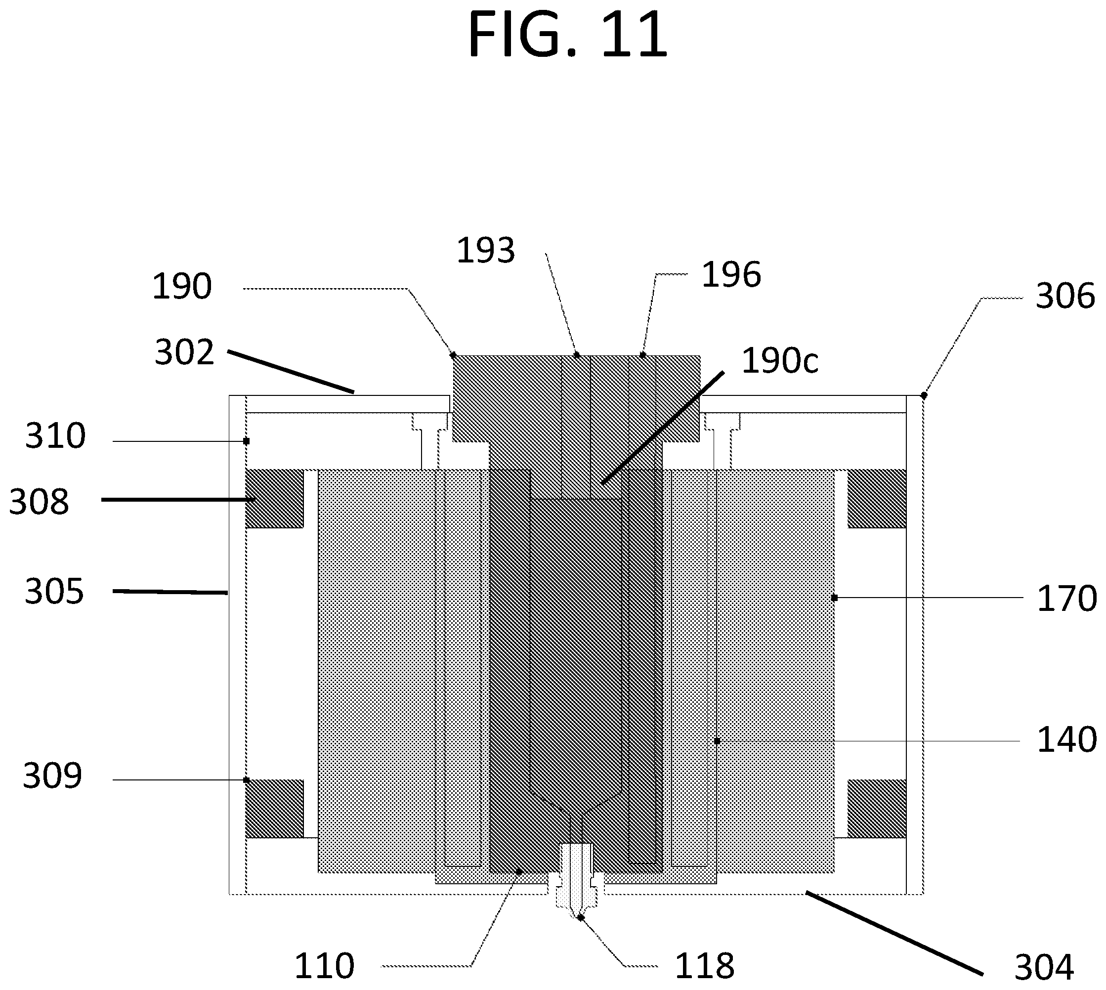
[0033] FIG. 11 is a cross-sectional view of the electrospinning melt head assembly of FIG. 1 within the support assembly of FIG. 9;
[0034] FIG. 12 is a diagram of an embodiment of an electrospinning system;
[0035] FIG. 13 is a diagram of signal communication between a control and processing system and various other components of the electrospinning system of FIG. 12;
[0036] FIG. 14a is an excursion profile;
[0037] FIG. 14b is another example of an excursion profile;
[0038] FIG. 15 is a perspective view of a cap of the syringe assembly of FIG. 2
[0039] FIG. 16 is a bottom view of the cap of FIG. 15;
[0040] FIG. 17 is perspective view of a syringe cap of the electrospinning melt head assembly of FIG. 1;
[0041] FIG. 18 is a top view of the syringe cap of FIG. 17;
[0042] FIG. 19 is a side view of the syringe cap of FIG. 17;
[0043] FIG. 20A-F illustrate some aspects of an example implementation of the current subject matter; and
[0044] FIG. 21 is a table that details certain technical specifications of an embodiment of an electrospinning system that can be similar to the electrospinning system of FIG. 12.
DETAILED DESCRIPTION
[0045] Certain exemplary embodiments will now be described to provide an overall understanding of the principles of the structure, function, manufacture, and use of the systems, devices, and methods disclosed herein. One or more examples of these embodiments are illustrated in the accompanying drawings. Those skilled in the art will understand that the systems, devices, and methods specifically described herein and illustrated in the accompanying drawings are non-limiting exemplary embodiments and that the scope of the present invention is defined solely by the claims. The features illustrated or described in connection with one exemplary embodiment may be combined with the features of other embodiments. Such modifications and variations are intended to be included within the scope of the present subject matter. Further, in the present disclosure, like-named components of the embodiments generally have similar features, and thus within a particular embodiment each feature of each like-named component is not necessarily fully elaborated upon.
[0046] Electrospinning can include a method of producing polymer fibers that utilizes electrical potential to draw liquid polymer threads across a gap between a conductive source emitter, such as a nozzle, and a conductive collector, or counter electrode. This process can be used to produce scaffolds, which cells and tissue can be seeded and grown on. One way this process can be improved is by reducing heat fluctuation in the polymer to achieve uniform melting of the polymer and hence uniform extrusion. Uniform extrusion can improve control of properties of the scaffold such as, e.g., porosity. With greater control of the properties of the scaffold, a more repeatable scaffold construction can be achieved, and the properties of the scaffold can be optimized to tissue growth. Additionally uniform geometries can provide ideal matching between cell sizes and scaffolds, provide the potential for mechanical cues from the uniform geometry e.g., enhanced nerve guides, provide predictable (by model) mechanical characteristics of scaffolds in dynamic settings e.g., aorta, and provide independence of fiber diameter and pore size in the scaffold. The temperature of the melt head can be monitored and tracked over time to determine the stability of the system. The tracking can be performed using a heat sensor such as a PT100 resistance temperature device (RTD) and an analog I/O device to measure and control the process. ("Pt" is the symbol for platinum, "100" for the resistance in ohms at 0.degree. C.). Additionally, tracking can be performed using (1) data logging with a computer and a thermocouple and/or RTD and (2) an error term e in a proportional-integral-derivative (PID) controller. The error term e can be a difference between a set point and a measured temperature, and can be integrated over the fabrication time of a scaffold (minutes to hours). Stability can be effected by (1) an auto-tune function on the PID controller but can also be determined by (2) tuning/stability methods such as Ziegler-Nichols tuning. The stability can ensure that the emitter reaches and maintains an ideal temperature with minimal overshoot.
[0047] Another way the electrospinning process can be improved is by measuring deposited material during an experimental run using load sensors on the collector to allow the user to monitor the rate of extrusion. For example, a single load cell capable of measuring micro-newton forces as a function of time f(t) can be employed. The load cell can be placed between movable stage and a counter electrode. The load cell can have sufficient dynamic range to receive the weight of the platform and still measure small forces. A signal from the load cell can be low pass filtered to derive a signal changing slowly with increasing force due a mass of deposited material. Such a signal can also be used to modulate the material deposition rate. Any rapid changes in f(t) may signal erroneous or non-uniform deposition and can signal an alarm state in software. Additionally, using a rectified sinusoidal excursion profile during extrusion can provide smoother linear excursions and hence better deposited fiber structures. As another example, active measurement and feedback of the electrical field between the emitter and the collector from either current or charge sensors can allow the applied voltage to be controlled, thereby allowing the electrical field density to be maintained.
[0048] In some implementations, feedback to increase the separation distance with every pass can be monitored and controlled and combined with any control of the electric field to ensure consistency of the process theatre with every pass.
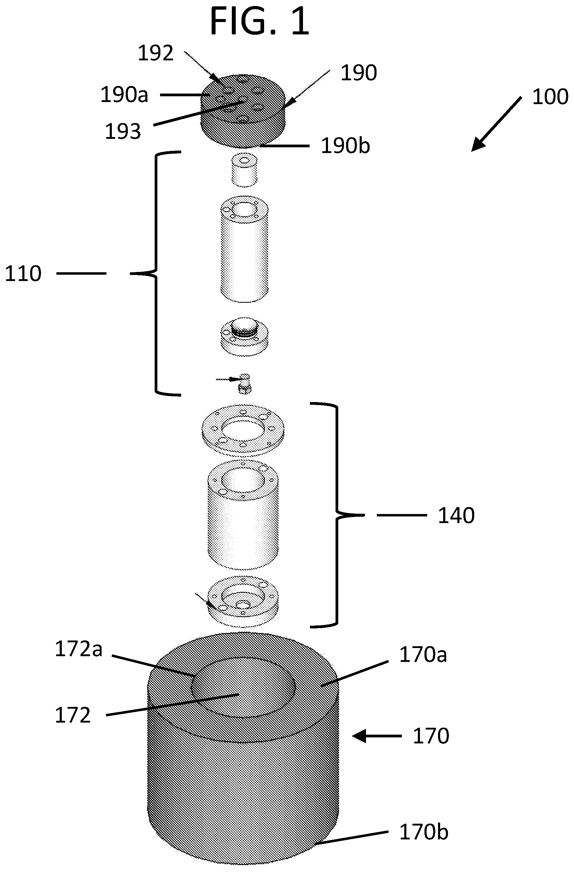
[0049] FIG. 1 shows an exploded view of an exemplary embodiment of an electrospinning melt head assembly 100. The melt head assembly 100 can include a syringe assembly 110, a heater assembly 140, a high-temperature insulation sleeve 170, and syringe cap 190. The syringe assembly 110 can function to retain and controllably deposit a polymer onto a substrate. The syringe assembly 110 can be received within the heater assembly 140, which can function to heat the polymer to a desired temperature, and the heater assembly 140 can be inserted into the insulation sleeve 170. The melt head cover can be positioned over a proximal end of the syringe assembly 110 and the heater assembly 140 to provide a layer of thermal insulation while allowing access to the syringe assembly 110 and the heater assembly 140. The specific components of the electrospinning melt head assembly 100 will be discussed in more detail below.
[0050] FIG. 2 shows an enlarged view of the syringe assembly 110 of FIG. 1. The syringe assembly 110 can include a syringe 112, a plunger 114, a cap 116, and a nozzle 118. As shown in FIGS. 1-2, the syringe 112 can have a substantially cylindrical geometry and can include a first opening 120a on a proximal end 112a, a second opening (not shown) on a distal end 112b, and a passage 120 extending therebetween, where the passage can extend along a central axis A2. The passage 120 that extends from the proximal end 112a to the distal end 112b can receive a polymer to be heated and extruded, deposited, or spun, onto a substrate. The opening 120a in the proximal end can receive the plunger 114, which can have at least one or more sealing elements 113 such as, e.g., O-rings, which can form a seal with a wall of the passage 120 of the syringe 112. In some embodiments, the plunger can have two sealing elements 113. In some embodiments, the plunger can be made of stainless steel. The plunger can translate proximally and distally within the passage 120 of the syringe 112 to control extrusion of the polymer. In practice, there are a number of ways that the position of the plunger 114 can be controlled. For example, the position of the plunger 114 can be altered by applying positive air pressure to a proximal end 114a of the plunger 114. Alternatively, a shaft can be coupled to the opening 115 in the proximal end 114a of the plunger, and force can be applied to the plunger 114 via the shaft. Adjusting the position of the plunger 114 using air pressure can be beneficial because it can simplify construction and reduce costs. Air or some other appropriate gas pressure can be applied directly to the molten polymer to extrude it through the nozzle. The method of operation is discussed in more detail below.
[0051] The cap 116 can function to couple the nozzle 118 to the syringe 112 and to provide access to the passageway of the syringe 112 through the distal end 112b. In the illustrated example, the cap 116 has a substantially cylindrically body, and includes a cylindrical mating feature 122 that extends in a proximal direction. The mating feature 122 can allow the cap 116 to be releasably coupled to the syringe 112 via the second opening on the distal end 112b of the syringe 112. The cap 116 can be coupled to the syringe 112 in any number of ways. For example, the mating feature 122 can have threads that can mate with threads in the second opening of the syringe 112. Alternatively, the mating feature 122 and the second opening can be coupled via, e.g., friction fit. In some embodiments, the mating feature 122 can include seals 124 disposed on an outer surface thereof. The mating feature 122 can be received within the second opening of the syringe 112, and the seals 124 can form a seal between the mating feature 122 and the passage 120 of the syringe 112. In some embodiments, the seals can include O-rings that can be made of perfluoro-elastomers FFKM. Additionally, the mating feature 122 can have a curved face 117 that can make with a distal end 114b of the plunger.
[0052] As shown in FIGS. 1-2, the syringe 112 and the cap 116 can include bores 126a, 126b, and bores 126c, 126d, all of which can be threaded, and temperature measurement channels 128a, 128b. The bores 126a, 126b can allow the syringe 112 to be coupled to the cap 116. FIGS. 15-16 show enlarged views of the cap 116. As shown in FIGS. 2, 15, and 16, bores 126b, 126d can be larger than bores 126a, 126c. This can help to ensure that the cap 116 and syringe 112 are properly aligned during assembly. Bores 126a can align with bores 126b, and bore 126c can align with bore 126d, and the syringe 112 can be coupled to the cap 116 via coupling elements such as, e.g., screws or bolts, that can extend through the bores 126a, 126b, 126c, 126d. The temperature measurement channels 128a, 128b can receive a temperature measurement sensor such as, e.g., a thermocouple, PT100 RTD, and the like that can extend through the syringe 112 and into the cap 116 to monitor the temperature of the cap 116 as close to the nozzle 118 as possible. Although not illustrated, the syringe 112 and cap 116 can include multiple temperature measurement channels that can receive temperature measurement sensors. Including more than one channel can allow multiple temperatures to be taken at various positions along the length of the syringe 112 and cap 116. In an exemplary embodiment, the syringe 112 and cap 116 can be made from stainless steel. Stainless steel can provide a good combination of corrosion resistance, thermal conductivity, and machinability. However, the syringe 112 and cap 116 can be made of any corrosion resistant material, such as e.g., titanium, nickel, or any other material suitable for the described purpose. In some embodiments, the cap 116 can be integral with the syringe 112.
[0053] As shown in FIG. 3, the nozzle 118 can include a central passage 130 that extends through a proximal mating portion 131, and a distal extrusion portion 132. The central passage 130 can have a first portion 135 with a first diameter, and a second portion 137 having a second diameter. The first portion 135 can extend from an inlet 130a on a proximal end 118a of the proximal mating portion, and the second portion 137 can lead to an outlet 130b on a distal end 118b of the distal extrusion portion 132. The distal spray portion 132 can include an internal inwardly tapering surface 132a, which can create a transition region that can couple the first portion 135 of the passage 130 to the second portion 137 of the passage 130. The internal inwardly tapering surface 132a can result in the outlet 130b of the nozzle 118 having a smaller diameter than the inlet 130a of the nozzle 118. In some embodiments, a coating of a conductive material can cover part of the extrusion portion 132 of the nozzle 118. The coating can act as a high voltage electrode when connected to an appropriate high voltage source.
[0054] In some implementations, a high voltage source can be included that applies a voltage between 0 and 20 kV. In some implementations, the voltage source can provide a voltage of 1 kV, 2 kV, 5 kV, 10 kV, 15 kV, 20 kV, 25 kV, 30 kV, 40 kV, or more. The voltage supply can provide voltage resolution 10 V, for example. In some implementations, the voltage source can provide a maximum current of 0.18 mA. In some implementations, the voltage source can provide a maximum current of 0.01 mA, 0.1 mA, 0.2 mA, 0.3 mA, 0.6 mA, 1.0 mA, 10 mA, 100 mA, or more.
[0055] In the illustrated embodiment, the proximal mating portion 131 of the nozzle 118 can include threads that can mate with threads in an opening 119 (shown in FIG. 16) in the cap 116. In an exemplary embodiment, the nozzle 118 can be made of a material that has thermal expansion coefficient that is greater than that of the cap 116. For example, if the cap 116 is made of a stainless steel, the nozzle 118 can be made of brass. Therefore, when the melt head assembly 100 is heated, the nozzle 118 can expand more than the cap 116, which can help form a seal between the threads on the mating portion 131 of the nozzle and threads in the opening in the cap 116.
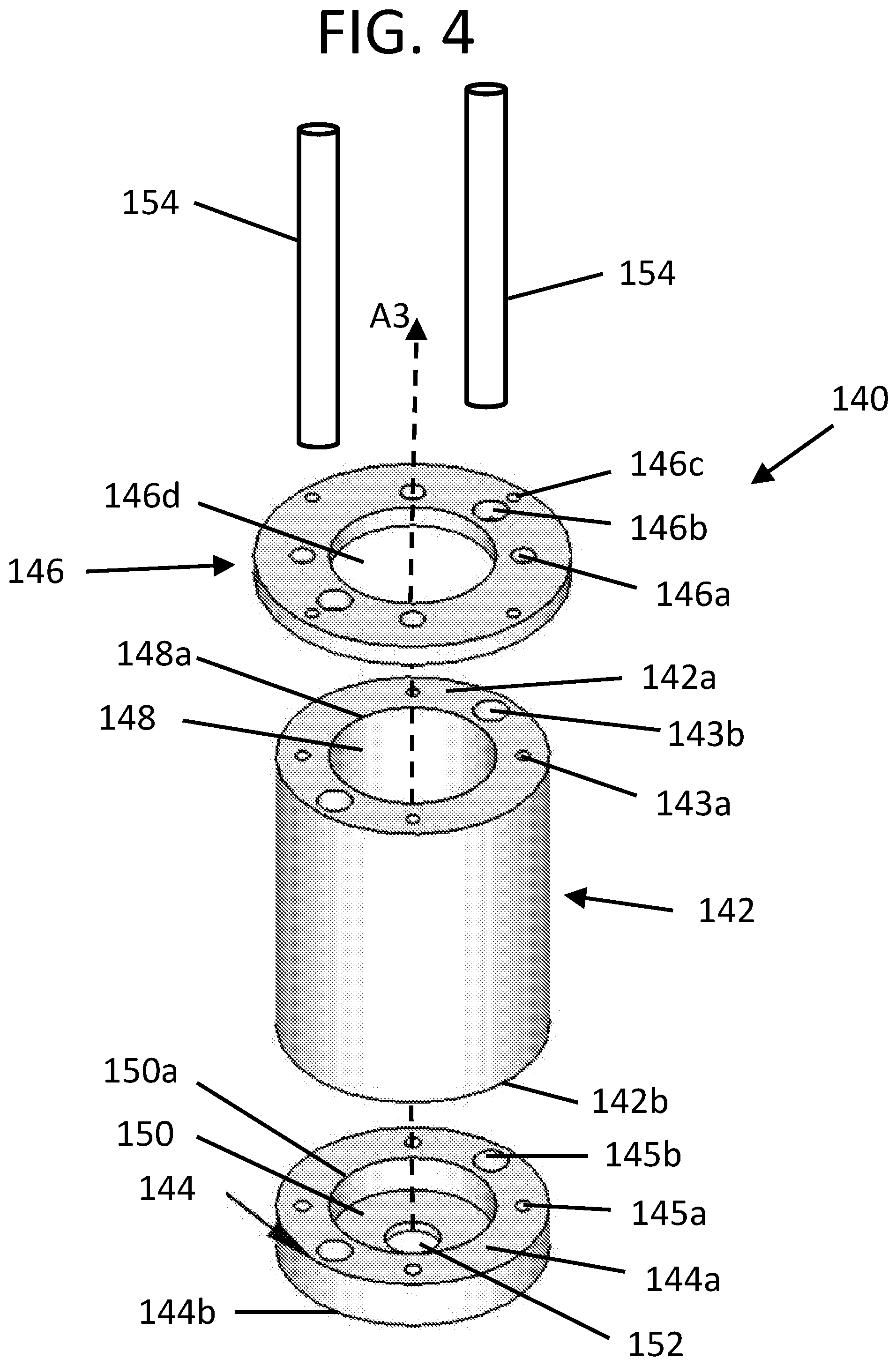
[0056] In order to provide heat to the polymer that is within the syringe 112, the syringe assembly 110 can be inserted into the heater assembly 140. FIG. 4 shows an enlarged view of the heater assembly 140 shown in FIG. 1. The heater assembly 140 can include heating elements 154, a heating member 142, or body, which can be in the form of, e.g., a cylindrical sleeve, as well as a heater cap 144, and a mounting flange 146. The heating member 142, heater cap 144, and mounting flange 146 can all have substantially cylindrical geometries. The mounting flange 146 can include sleeve coupling bores 146a, heater bores 146b, support coupling bores 146c, and a central bore 146d. The sleeve coupling bores 146a can align with coupling bores 143a on a proximal end 142a of the heating member 142, and can allow the mounting flange 146 to be coupled to the heating member 142 using a coupling element such as, e.g., a screw or bolt. The support coupling bores 146c can function to allow the heater assembly 140 to be coupled to a support frame, which is discussed in more detail below.
[0057] As shown in FIG. 4, the heating member 142 can have a substantially cylindrical geometry and can include a first opening 148a on a proximal end 142a, a second opening (not shown) on a distal end 142b, and a passage 148 extending therebetween. The heating member 142 can include the coupling bores 143a as well as heater bores 143b on the proximal end 142a. As described above, the coupling bores 143a on the heating member 142 can align with coupling bores 146a on the mounting flange 146, and can allow the heating member 142 and mounting flange 146 to be coupled using coupling elements such as screw or bolts. The heater bores 143b can extend through the length of the heating member 142 and can align with heater bores 146b of the mounting flange 146 on the proximal end 142a of the heating member 142, and with heater bores 145b of the cap 144 on the distal end 142b of the heating member 142.
[0058] The heater cap 144 can include the heater bores 145b as well as coupling bores 145a. The heater cap 144 can have a recessed region 150 extending distally from an opening 150a in a proximal end 144a, and can also include a bore 152 extending through the distal end 144b of the cap 144. The central bore 146d, passage 148, recessed region 150, and bore 152 can share a central axis A3 and can align such that the syringe assembly 110 can be received within the heater assembly 140. The recessed region 150 of the cap 144 can receive, and seat, a distal portion of the syringe assembly 110, and the bore 152 can allow the nozzle 118 to extend through the distal end 144b of the heater cap 144.
[0059] Heating elements 154 such as, e.g., cartridge heaters, can be used to provide heat to the syringe assembly 112. In some embodiments, the heating elements 154 can be 200 W cartridge heaters. In other embodiments, the heating elements can generate greater than 200 W of heat, or less than 200 W of heat. The heating elements 154 can be inserted through heater bores 146b and 143b, and can extend into heater bores 145b in the heater cap 144. The heating elements 154 can heat the mounting flange 146, the heating member 142, and the heater cap 144, which can in turn heat the syringe assembly 110 and the polymer that can be within the syringe 112. In some embodiments, the heating elements 154 can heat the heater assembly 140 up to temperature of approximately 250.degree. C.
[0060] The heating member 142, mounting flange 146, and cap 144 can be made of any material suitable for the described purpose. However, in an exemplary embodiment, the heating member 142, mounting flange 146, and cap 144 can be made of aluminum. Aluminum has a relatively high thermal conductivity, which can result in a more uniform temperature distribution since heat from the heating elements 154 can conduct well through each of the parts of the heater assembly 140.
[0061] The syringe assembly 110 and heater assembly 140 can be insulated using, e.g., the insulation sleeve 170, to minimize heat loss and improve temperature control. Referring back to FIG. 1, the insulation sleeve 170 can include a passage 172 that can extend between an opening 172a in a proximal end 170a of the insulation sleeve 170 and an opening (not shown) in a distal end 170b of the insulation sleeve 170. The syringe assembly 110 and the heater assembly 140 can be inserted into the passage 172 of the insulation sleeve 170. The insulation sleeve 170 can be made of any insulating material that can withstand the maximum temperature of the heating elements 154. In some embodiments, the insulating sleeve can be made of calcium silicate. The insulation sleeve 170 and heating elements 154 can form a concentrated heating zone. This concentrated heating zone focuses the heat in a volume of the syringe where, in operation, polymer is loaded.
[0062] In order to provide insulation at the proximal end of the syringe 112, the syringe cap 190 can be positioned over the proximal end 112a of the syringe and/or the mounting flange 146. The syringe cap 190 have a substantially cylindrical geometry, and can include an array of bore holes 192 that can extend from a proximal end 190a syringe cap 190 to a distal end 190b of the syringe cap 190. In some embodiments, a portion of the cap 190 can extend into the passage 120 of the syringe 112 such that it forms a seal with the wall that defines the passage 120. In some embodiments, the syringe cap 190 can be made of, for example, DuroBest.RTM. 280 (agk), Polyether ether ketone (PEEK) or IGLIDUR.RTM. (IGUS INC., East Providence R.I. 02914). FIGS. 17-19 show various views of the syringe cap 190. The bore holes 192 can provide access to the syringe assembly 110 and/or the heater assembly 140. For example, at least one bore hole 196 can provide access to the temperature measurement channel 128a such that a temperature sensor 129 can be inserted into temperature measurement channels 128a, 128b. In some embodiments, the temperature sensor 129 can be a 4 mm PT100 temperature sensor, or a type K thermocouple. In some embodiments, the syringe cap 190 can include coupling bores 195a, 195c, which can align with bores 126a, 126c of the syringe 112 and can allow the syringe cap 190 to be coupled to the syringe 112 using coupling elements such as, e.g., screws or bolts. The syringe cap 190 can also include mounting bores 197, which are discussed more below. A hose fitting can be coupled to an air inlet port 193 such that gas pressure can be applied the plunger to force polymer liquid from the nozzle. Alternatively, a shaft can extend through the inlet port 193 and can be coupled to the opening 115 in the proximal end 114a of the plunger. The shaft can then apply mechanical force to the plunger to move it proximally and/or distally within the passage 120 of the syringe 112. In some implementations, gas can be applied directly to the molten polymer. In some implementations, a solenoid valve can be utilized to control the gas pressure, including applying positive and negative pressure on the plunger. This approach can provide improved control of the extrusion process.
[0063] In some embodiments, a heater assembly can have a unibody configuration rather than having multiple components such as those described with regard to heater assembly 140. The heater assembly can also have heating elements embedded into it. FIGS. 5-6 show an example of an embodiment of a heater assembly 240 that has a unibody configuration and that can have one or more embedded heating elements 254. Temperature sensors can also be embedded into the unibody configuration. FIG. 5 shows a perspective view of the heater assembly 240, and FIG. 6 shows a side cross-sectional view of the heater assembly 240. The heater assembly 240 can have a body 242 that can have a substantially cylindrical geometry, and it can include a central passage 248 that can extend from an opening 248a in a proximal end 240a of the heater assembly 240, toward a distal end 240b of the heater assembly 240. The proximal end 240a of the heater assembly 240 can include a flange 246 that can extend radially outward. The flange 246 can have support coupling bores 246c that can function similarly to support coupling bores 146c. The distal end 240b of the heater assembly can have a bore 252 that can receive a nozzle such as nozzle 118 of the syringe assembly 110. In the illustrated embodiment, the central passage 248 and the bore 252 can share a central axis A4.
[0064] The heater assembly 240 can also include a port 260 having a radial passage 262 that can extend from an end 260a of the port 260 to the central passage 248. The port 260 can allow wires to be passed into and out of the passage 248. For example, wires from the temperature sensor 129 that can monitor the temperature of a syringe assembly such as syringe assembly 110 can be passed through the passage 262 of the port 260.
[0065] In the illustrated example, rather than inserting heating elements into bores of the heater assembly, as described with regard to heater assembly 140, the heating elements 254 can be embedded in a concentrated heated region 256 of the body 242 of the heater assembly 240. In some embodiments, the heated region 256 can be limited to a lower half, or distal half, of the heater assembly 240. The heating elements 254 can be one or more resistive heaters that can encircle, or wind around, the passage 248 within the body 242 of the heater assembly 240. The heating elements 254 can receive power from a power source via a cable 257 that can extend out of the body 242 of the heater assembly 240. Using a heater assembly configuration that includes heating elements that wrap around the passage 248 can provide more uniform heat transfer to the syringe assembly 110, which can result in the polymer having a more uniform temperature distribution. Such a configuration can increase the precision of a control system that can be used to monitor and maintain the temperature of the syringe assembly 110 and/or the polymer that is within the syringe 112. By creating a more uniform temperature profile, temperature measurements can be less sensitive to the exact position of the temperature sensor 129, which can result in increased accuracy and precision of the temperature measurement. In some embodiments, the passage 262 of the port 260 does not extend into the passage 248. In that case, passage 262 can be used to pass cables that can couple to the heating elements 254 or temperature sensors within the walls of the heater assembly. For example, cable 257 can extend from the heating elements 254, up to passage 262, and out of the heater assembly 240, rather than extending out of the body 242 of the heater assembly 240.
[0066] FIGS. 7 and 8 show how the syringe assembly 110 can be received within the heater assembly 240. FIG. 7 shows the syringe assembly 110 aligned with the opening 248a in the proximal end 240a of the heater assembly. FIG. 8 shows the syringe assembly 110 positioned within the passage 248 of the heater assembly.
[0067] Regardless of which heater assembly is used, the melt head assembly 100 can be supported within a support assembly. The support assembly 300, shown in FIG. 9, can include upper and lower covers 302, 304, side covers 305, 306, upper and lower support frames 308, 309 and heater assembly support plate 310.
[0068] The lower cover 304 can generally be in the shape of a square or rectangular plate. In some embodiments, the lower cover 304 can be made of Polytetrafluoroethylene (PTFE), Polyether ether ketone (PEEK) and/or another electrically insulating and thermally resistant material. The lower cover 304 can have a recessed region 312 extending distally from an opening 312a in a proximal surface 304a, and can also include a bore 352 extending from the recessed region 312 to a distal surface 304b of the cover 304. The lower cover 304 can also have coupling bores 314a that can extend distally from the proximal surface 304a of the lower cover 304. The recessed region 312 can be sized and shaped to receive a distal portion of the insulation sleeve 170. The bore 352 can generally align with bore 252 of the heater assembly 240 such that it can receive the nozzle 118 of the syringe assembly 110.
[0069] As illustrated in FIG. 9, the support assembly 300 can include upper and lower support frames 308, 309, or structural ribs. In some embodiments, the upper and lower support frames 308, 309 can be made of aluminum. The support frames 308, 309 can generally be square or rectangular in shape and can have perimeter dimensions that can be approximately equal to those of the lower cover 304. The support frames 308, 309 can have passages 316, 318 that extend from proximal surfaces 308a, 309a to distal surface 308b, 309b of the frames. In the illustrated example, the passages 316, 318 have generally square shapes. However, the passages 316, 318 can have any geometry suitable to receive and retain the melt head assembly 100. In addition to the passages 316, 318 for receiving the melt head assembly 100, the support frames 308, 309 can have first sets of coupling bores 320a, 321a, second sets of coupling bores 320b, 321b, and third sets of coupling bores 320c, 321c.
[0070] In the illustrated example, the side covers 305, 306 include coupling bores 319b. The coupling bores 319b can align with coupling bores 320b, 321b of the support frames 308, 309 to allow the side covers 305, 306 to be coupled to the support frames 308, 309 using, e.g., a screw, bolt, or pin. As shown in FIG. 9, the support plate 306 can also include larger coupling bores 319c as well as a passage 322. In some embodiments, passage 322 can be used to feed power cables to the cartridge heaters 154, or to the heating elements 254, from an external power supply. These cables can be managed by the use of trunking and labeling. The cables can further include inlet filters to improve the electro-magnetic compatibility (EMC) characteristics of the system and/or prevent the electrical leakage. The bores 320c, 321c can align with bores 319c on the side cover 306, and they can allow the melt head assembly 100 and the support assembly 300 to be coupled to a mounting assembly (not shown) using coupling elements such as, e.g., screws, bolts, or another spacing mechanism such as spacing posts, rods, or an adaptor plate. In some embodiments the side covers 305, 306 can be made of aluminum and can be powder coated white. Although the side cover 305 is illustrated as a three-sided piece of folded aluminum, each side of the side cover 305 can be an individual piece similar to side cover 306.
[0071] FIG. 10 shows an enlarged view of the upper cover 302 and the heater assembly support plate 310. In some embodiments the upper cover 302 can be made of aluminum and can be powder coated white, and the heater support plate 310 can be made of Polyether ether ketone (PEEK). The heater assembly support plate 310 can also generally be square or rectangular in shape and can have perimeter dimensions that can be approximately equal to those of the lower cover 304. The support plate 310 can have a recessed region 324 extending distally from an opening 324a in a proximal surface 310a, and can also include a bore 326 extending from the recessed region 324 to a distal surface 310b of the support plate 310. The support plate 310 can also include coupling bores 328a, and first and second sets of countersunk coupling bores 330a, 332a. Additionally, the recessed region can include syringe cap 190 mounting bores 325. The cap mounting bores 325 can align with the mounting bores 197 on the syringe cap, which can allow the syringe cap 190 to be coupled to the heater assembly support plate 310 using coupling elements such as, screws, bolts, or other coupling elements suitable for the described purpose
[0072] The upper cover 302 can generally be square or rectangular in shape, and can include coupling bores 334a that can align with the coupling bores 328a in the support plate 310, and a central bore 336 that can align with the opening 324a in the support plate 310.
[0073] The support assembly 300 can be assembled by coupling the various components using coupling elements such as, e.g., screws, bolts, and/or pins. The distal end 170b of the insulation sleeve 170 can be positioned in the recessed region 312 of the lower cover 304.
[0074] The distal surface 318a of the lower support frame 309 can be positioned over the proximal surface 304a of the lower cover 304 such that the coupling bores 320a align with coupling bores 314a. Coupling elements can be inserted into the coupling bores 314a, 320a to couple the lower support frame 309 to the lower cover 304.
[0075] The heater assembly 240 can be inserted into passage 172 of the insulation sleeve 170 such that bore 252 of the heater assembly 240 aligns with bore 352 of the lower cover 304. Although not shown, the insulation sleeve 170 can have a radial bore to allow the port 260 of the heater assembly 240 to pass therethrough. The electrospinning melt head assembly 100 and the support assembly 300 can be assembled as follows.
[0076] The syringe assembly 110 can be inserted into the heater assembly 240. A polymer that can be used for electrospinning can be inserted into the passage 120 of the syringe 112. The polymer can be in the form of beads.
[0077] The upper support frame 308 can be coupled to the side covers 305, 306 using coupling elements that can extend through some of the coupling bores 319b in the side covers 305, 306 and into the coupling bores 320b on the upper support frame.
[0078] The upper support frame 308, with the side covers 305, 306 releasably attached thereto, can be positioned over the insulation sleeve 170 such that the remainder of the coupling bores 319b align with the coupling bores 321b on the lower support frame 309.
[0079] The larger coupling bores 319c on the side cover 306 can be releasably attached to the third sets of coupling bores 320c, 321c on the upper and lower support frames 308, 309.
[0080] The heater support plate 310 can be positioned over the insulation sleeve 170, heater assembly 240 and syringe assembly 110. The heater support plate 310 can be releasably coupled to the proximal end 240a of the heater assembly 240 by coupling elements that can be inserted into countersunk coupling bores 330a on the heater assembly 240 and into coupling bores 246c on the proximal end 240a of the heater assembly 240. The heater support plate 310 can also be coupled to the upper support frame 308 via coupling elements that can be inserted into countersunk coupling bores 332a and into coupling bores 320a on the upper support 308.
[0081] The distal end 190b of the syringe cap 190 can be placed into the recessed region 324 of the heater support plate 310. Although not illustrated, the syringe cap 190 can have sealing elements that extend around its perimeter that can form a seal with the recessed region 324.
[0082] The upper cover 302 can be attached to the heater support plate 310 via coupling elements that can be inserted into coupling bores 334a in the upper cover 302 and into coupling bores 328a in the support plate 310.
[0083] If a multicomponent heater assembly, such as heater assembly 140, is used, it can be assembled as described above, and it can be incorporated into the melt head assembly 100 in the same manner as the heater assembly 240. FIG. 11 shows a cross-sectional view of the electrospinning melt head assembly 100, shown in FIG. 1, within the support assembly 300, illustrated in FIG. 9. As shown in FIG. 11, a portion 190c of the cap 190 can extend into the passage 120 of the syringe 112 such that it forms a seal with the wall that defines the passage 120.
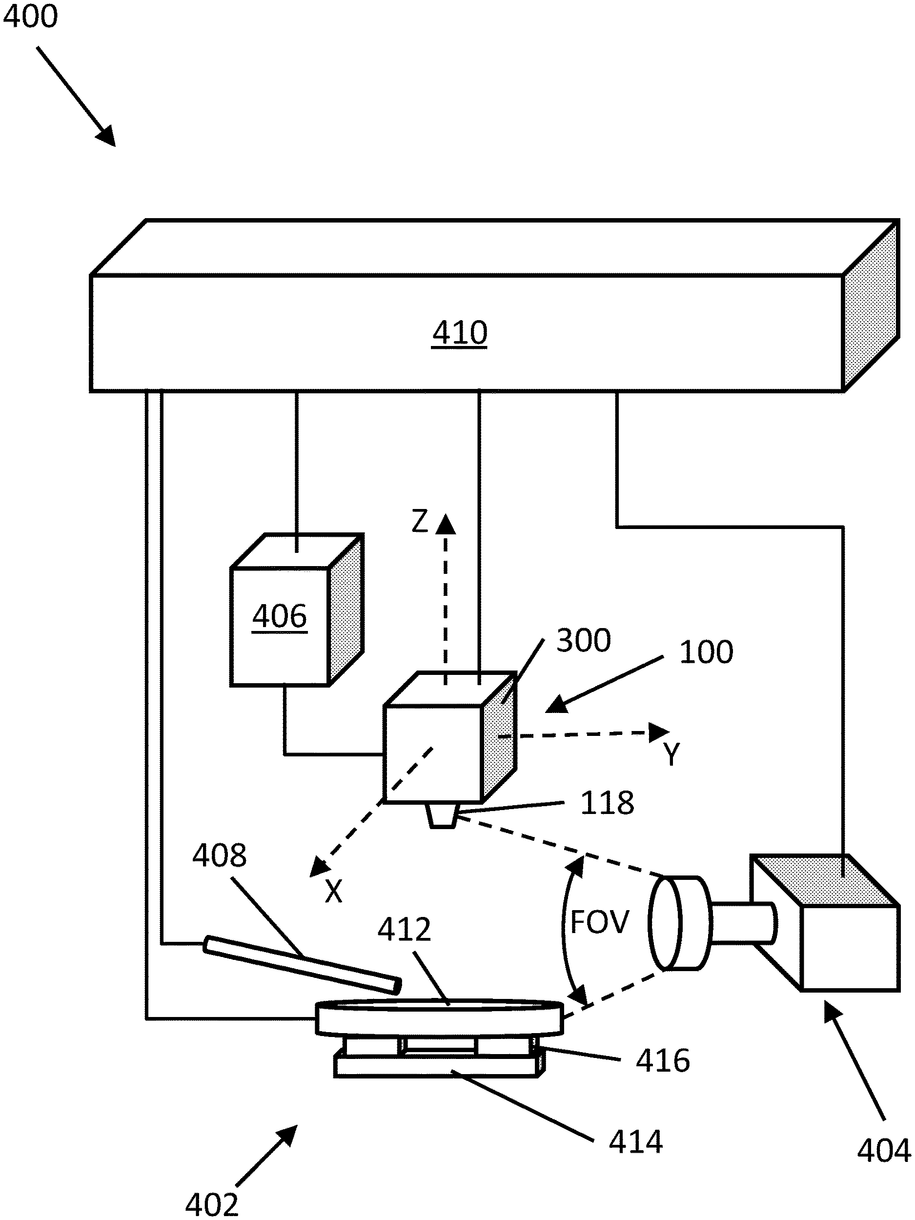
[0084] FIG. 12 shows a diagram of an embodiment of an electrospinning system 400. The electrospinning system 400 can include the electrospinning melt head assembly 100, including the support assembly 300, a collector assembly 402, an imaging system 404, a plunger drive system 406, a probe 408, and a control and processing system 410. The melt head assembly 100 can be assembled and coupled with the support assembly 300 as described above, and it can be mounted on a mount assembly (not shown) that allows the melt head assembly to be moved along X, Y, and Z axes.
[0085] As described above, the plunger 114 of the syringe assembly 110 can be driven by applying air pressure to the proximal surface 114a, or by using a rigid mechanical connector such as a rod. The plunger drive system 406 can deliver air or another mechanical force to the plunger to create proximal or distal displacement to expel polymer liquid or to draw it back into the syringe 112. In some implementations, the plunger drive system 406 can include a pump. The plunger drive system 406 can send and receive signals to and from the control and processing system 410 to control the position of the plunger 114, thereby controlling flow of polymer from the nozzle 118. In some embodiments, the plunger 114 can be omitted, thereby the applied air pressure directly expels polymer liquid or draws it back into the syringe 112. The gas that is supplied into the syringe 112 is not limited to air, but can also include any inert gases such as, e.g., nitrogen or argon. In some implementations, omitting the plunger 114 can be advantageous in some implementations because in implementations that utilize a plunger, molten polymer can extrude through the nozzle even when no driving force is applied. Due to the air tight fit between the piston and the walls of the melt chamber, any expanded air in the system during the heating phase may drive molten polymer through the nozzle as it may not be relieved.
[0086] As polymer is expelled from the nozzle 118, it can be deposited onto a collector 412 of the collector assembly 402. The collector assembly 402 can include the collector 412, a base 414, and one or more load sensors 416 that can be used to determine the amount of polymer that has been deposited onto the collector 412. By measuring the amount of polymer that has been deposited onto the collector, a rate of polymer extrusion from the nozzle 118 can be determined. In some embodiments, the nozzle 118 can be grounded, and high voltage power can be supplied to the collector 412 such that an electric field is created between the collector 412 and the nozzle 118. In some embodiments, the collector 412 can have a conductive coating that can allow it to function as an electrode. In other embodiments, the collector 412 can be conductive.
[0087] In addition to, or as an alternative to, using load sensors 416 to measure the amount of polymer deposited onto the collector 412, the imaging system 404 can be used in conjunction with machine vision software to determine an extrusion rate of the polymer and to track the amount of extruded polymer. The imaging system 404 can have a field of view (FOV) that includes the nozzle 118 and the collector 412.
[0088] As the polymer threads are deposited onto the collector 412, in a region sometimes referred to as the boundry, and the polymer scaffold increases in height, an electric field generated between the nozzle 118 and the collector 412 can change and/or weaken due to insulating properties of the polymer. The probe 408 can measure the electric field between the nozzle 118 and the collector 412. The probe 408 can be, e.g., a field mill, or an electric field meter (EFM). Alternatively, or additionally, the probe 408 can measure charge of the collector 412 and/or the polymer on the collector. Information about the electric field between the nozzle 118 and the collector 412 can be used to adjust power delivered to, or voltage of, the collector 412, thereby allowing the electric field density to be maintained. The information about the electric field can also be used to adjust the position of the electrospinning melt head assembly 100 in the Z direction with each pass, thereby altering the electric field. In some embodiments, the collector 412 can have a stippled and/or spiked surface, which can allow for a more consistent electric field density during polymer deposition. In some embodiments, the stipples and/or spikes can extend between approximately 1 mm and 2 mm, or less than 10 mm, from the surface of the collector. The stipples and/or spikes can be arranged in an array, they can have varying pitch. Regions of the collector 412 can also have stipples and/or spikes that can arranged in patterns with varying density. In other words, certain regions of the collector 412 can have stipples and/or spikes that can be more closely packed than they are in other regions of the collector 412.
[0089] The electrospinning process occurs over a short separation distance between the collector 412 and the nozzle 118. In a similar fashion to the electric field, as the scaffold increases in height with every pass, the separation between the collector 412 and the nozzle 118 can increase as well to retain a consistent deposition distance between the nozzle 118 and the previously laid fiber of polymer.
[0090] A position of the nozzle 118 can be monitored, and feedback can be used to increase the separation distance with every pass. The nozzle 118 can be monitored and controlled and combined with any control of the electric field to ensure consistency of the process theatre with every pass of the nozzle 118 over a given point on the collector 412.
[0091] FIG. 13 shows a diagram of signal communication between the control and processing system 410 and various other components of the electrospinning system 400. As shown in FIG. 13, the control and processing system 410 can include an image processing module 422, an electric field module 424, a load module 426, a plunger module 428, a heater module 430, and a collector module 432.
[0092] The heater module 430 can send and receive signals to and from the temperature senor 129 and the heating elements 254. In operation, a desired polymer temperature can be selected via the control and processing system 410. The selected temperature can correspond to an initial power that can be provided to the heating elements from a power supply. The temperature of the nozzle 118 can be measured using the temperature sensor 129 in temperature measurement channels 128a, 128b of the syringe assembly 110. The temperature sensor 129 can send temperature signals to the heater module 430, which can analyze the signals, calculate the temperature, determine an appropriate action for the heating elements 254, and send a corresponding heating signal to the to the heating elements 254. System behavior can be coordinated in hardware and software developed to signal condition multiple inputs (e.g., temperature, stage location, and material deposition rate) and perform computations on the inputs to produce outputs (e.g., heater coil power, plunger excursion, electric field potential). In some embodiments, a resistance temperature detector (RTD) such as a PT100 RTD can be used to measure the temperature of the nozzle 118. In that case, the heater module 430 can measure the resistance across the temperature sensor 129, and correlate that resistance to a temperature value. In other embodiments, a thermocouple, e.g., a type-K thermocouple, can be used to measure the temperature of the nozzle 118. A melting temperature of the polymer can be determined empirically prior to loading the polymer into the syringe 112. For example, phase change experiments can be conducted by heating and melting the polymer and measuring the temperature of the polymer throughout the heating and melting process. In some embodiments, the heating signal can come from a power supply of the heater module. The heater module 430 can include a proportional integral-derivative (PID) controller and can utilize PID control with an auto-tuning function to control power that is delivered to the heating elements 254. The input can be the temperature signal from the temperature sensor 129, and the output can be the heating signal. The auto-tuning function can determine a thermal response of the system over time and can calculate a system parameter to correctly drive the system. As described above, the temperature sensor 129 can be an RTD, a thermocouple, or both. If more than one temperature sensor 129 is implemented, one sensor can be used as a reference for the PID controller and another sensor can be used for monitoring the melting temperature of the polymer. Use of a type K thermocouple can be more dynamic than the PT100 temperature sensor. This can reduce or prevent overshoot of the polymer as the heater reaches a desired setpoint quicker and so can be close to a steady state by the time sufficient conduction occurs. This can include a gradual heating process compared to some embodiments. In addition, the use of separate monitor and control temperature probes can allow for fine temperature adjustment of the melt set point, which combats natural losses. In some implementations, the PID controller reference temperature can be built into the heating head such that it cannot be removed, which reduces the chance of overheating the system to the point of irreversible damage.
[0093] Once the temperature sensor is outputting a signal corresponding to the desired temperature of the polymer, the melt head assembly 100 can be left to heat for a period of time to ensure that it has reached thermal equilibrium. The polymer that is not in direct contact with the syringe 112 will melt due to the thermal conductivity of the loaded polymer. The time taken to melt all of the polymer will depend on the mass of the polymer and its thermal conductivity.
[0094] The PID temperature can further include a dual relay control on the heater power lines, temperature lockouts and internal alarms/latches to improve the user-safety and/or the performance of the device.
[0095] When the system has reached thermal equilibrium, the polymer can be extruded through the nozzle 118. High voltage power can be supplied to the collector 412 from the collector module 432. The collector module 432 can also monitor the voltage at the collector 412, and a position of the nozzle 118 in the X, Y, and Z directions. The plunger module 428 can also deliver a drive signal to the plunger drive system 406. The plunger drive system 406 can receive the drive signal and can provide air pressure to space between the proximal end 114a of the plunger 114 and a distal end 190b of the syringe cap 190 to drive the plunger 114 distally within the passage 120 of the syringe 112 to force polymer liquid from the nozzle 118. Alternatively, if the plunger is driven by a rod, the plunger drive system 406 can apply a force to the rod to displace the plunger. If the air pressure directly drives the melted polymer without a plunger, the plunger drive system 406 can receive the drive signal and can provide air pressure to space between the proximal end of the melted polymer and the distal end 190b of the syringe cap 190 to force polymer liquid from the nozzle. The rate of this natural extrusion can be dependent on the viscosity of the melted polymer. Low viscosity melted polymers can extrude very fast while high viscosity polymers can extrude very slowly.
[0096] At a critical point, as a polymer droplet extends from the nozzle 118 toward the collector, a stream of polymer liquid can erupt from the droplet. During travel from the nozzle 118 to the collector 412, the stream can dry. As the stream dries, or cools, a mode of current flow can change from ohmic to convective as charge migrates to the surface of the forming fiber. While traveling toward the collector 412, the collector module 432 can deliver a motion signal to the mounting assembly (not shown) that retains the melt head assembly 100 to move the melt head assembly 100 in the X-Y plane to create small bends in the fiber, which can cause the fiber to thin and lengthen, until it is deposited onto the collector. In some implementations, the mounting assembly retains the collector 412 to move the collector in the X-Y plane to crease the small bends in the fiber, which can cause the fiber to then and lengthen, until it is deposited onto the collector 412. The thinning and elongation as a result of the X-Y motion can lead to the formation of uniform fibers with nanometer scale diameters. The X-Y motion of the melt head assembly 100 and/or the collector 412 can be achieved by a XYZ drive system that can be implemented with various actuation mechanisms such as, e.g., a ball-and-screw drive system or a linear positioner. When the linear positioner is used, linear interpolation can be facilitated to maintain a constant speed during curve operations, with which there is no acceleration or deceleration during cornering and hence grids with round features can be deposited. In addition, constant linear speed can prevent curly melt electrospun fibers.
[0097] In some embodiments, G-code can be used to create polymer scaffolds at certain porosity and density. In other embodiments, position table logic can be used to command the motion of the melt head assembly 100. An excursion profile of linear stages of motion can be important to creating thin, straight fibers. Extrusion and deposition of straight fibers can be dependent on the velocity profile of the linear stages of motion. If the velocity is not suitably matched to the extrusion rate (the rate of electrospinning), i.e., the extrusion rate is too fast or too slow, the deposited fibers can be curly, rather than straight. An excursion profile 500 can be seen in FIG. 14a. The excursion profile 500 shows that each pass has a first portion 502 that shows linear acceleration, a second portion 504 that shows constant velocity, and a third portion 506 that shows constant linear deceleration at the end of the pass. This excursion profile 500 is abrupt in its nature given the short and fast nature of the excursion. Rather than using the excursion profile 500 shown in FIG. 14a, an excursion profile 600 that utilizes a rectified sinusoidal profile 602, as shown in FIG. 14b, can provide smoother linear excursions and hence better deposited fibers.
[0098] Referring back to FIG. 13, as polymer fibers are deposited onto the collector 412, the imaging system 404 can monitor the rate and volume of polymer extrusion from the nozzle 118. The imaging system 404 can deliver imaging signals to the image processing module 422. The image processing module 422 can deliver rate signals to the collector module 432 and the plunger module 428. The collector module 432 and plunger module 428 can receive the rate signals and can deliver signals to the collector 412 and to the plunger drive system 406 to adjust the voltage of the collector 412 and the pressure applied to the plunger 114, respectively. By adjusting the voltage at the collector 412, the electric field density can be maintained.
[0099] The load sensors 416 can measure pressure from the weight of the polymer fibers on the collector 412 and can deliver corresponding signals to the load module 426. The load module 426 can receive the signals, determine how much polymer is on the collector 412, as well as the rate of extrusion, and can deliver corresponding load signals to the collector module 432 and the plunger module 428. For example, the mass of the polymer on the collector 412 can be determined by the load sensors 416 and the load module 426. A volume of polymer can be determined using a known density, molar mass, and/or molecular weight of the polymer, in conjunction with measured mass on the collector 412. A rate of polymer extrusion can be found by determining a change in the mass/volume of polymer on the collector 412 and dividing by a time that elapsed between measurements. Load signals can be analog and can be converted to digital by the load module 426. The collector module 432 and the plunger module 428 can deliver signals to the nozzle 118 and to the plunger drive system 406 to adjust the voltage of the nozzle 118 and the rate of extrusion, respectively.
[0100] The probe 408 can measure the strength of the electric field between the nozzle 118 and the collector 412 and can deliver field signals to the electric field module 424. The field signals can correspond to the strength of the electric field between the nozzle 118 and the collector 412, and/or the charge of the collector 412. In some embodiments, the electric field module 424 can include a micro-ammeter or other charge/current detector. Therefore, the collector 412 can deliver charge signals to the electric field module 424. The charge signals can correspond to the charge of the collector 412. The electric field module 424 can receive the field signals and charge signals from the probe 408 and collector 412, respectively, and can deliver a signal to the collector module 432. The collector module 432 can receive the signal and can adjust the voltage of the collector 412 or adjust the position of the melt head assembly 100 in the Z axis, thereby adjusting a gap distance between the nozzle 118 and the collector 412. The collector module 432 can also deliver a signal to the plunger module 428, which can deliver a signal to the plunger drive system 406 to adjust the rate of extrusion.
[0101] The rate of polymer extrusion can also be reduced or stopped at any point during the extrusion process. For example, of the rate of polymer extrusion determined to be too high, or if extrusion is complete, the plunger module 428 can deliver a signal to the plunger drive system 406 indicating that the plunger 114 should be retracted. The plunger drive system 406 can create vacuum pressure behind the plunger 114 to draw it proximally within the passage 120 of the syringe 112, thereby drawing the polymer liquid away from the nozzle 118. In other words the air pressure applied to the proximal end of the plunger 114 can be reduced sufficiently to draw the plunger proximally within the passage 120 to stop, or reduce, flow of polymer from the nozzle 118.
[0102] In the embodiment of the electrospinning system 400 described above, the nozzle 118 is grounded while a voltage is applied to the collector 412. However, in some embodiments, a voltage can be applied to the nozzle 118 and the collector 412 can be grounded or provided another voltage. Such a configuration can generate an electric field between the nozzle 118 and the collector 412 that can facilitate polymer extrusion.
[0103] In some embodiments, electric, fluidic and temperature subsystems can be integrated into a single enclosure. The subsystems can further include a safety circuitry for improved user-safety. Moreover, the electric, fluidic and temperature subsystems can be controlled by a closed-loop control by, e.g., a programmable logic controller (PLC) over an Ethernet IP protocol. Using a PLC can reduce the manufacturing assembly time and allow the user to store operating parameters into memory for repeatable deployment. Further, by using a PLC, the system can be setup so that it is operable when all operating parameters are within an acceptable range. The PLC can also include safety features to prevent the heater overheating, to control the high voltage module, and to monitor the system pressure. In addition, the PLC of the system can have a human-machine interface (HMI) to provide a standalone operating without requiring a PC to interact with an operator in regards to operating parameters such as pressure, temperature, speed, and number of cycles, to provide the operator with feedback, errors, current program, temperatures, speeds, pressure values and voltage values.
[0104] FIG. 20A-F illustrate some aspects of an example implementation of the current subject matter. Melt electrospinning can be considered as an alternative polymer processing technology that can enable fabrication of three dimensional scaffolds. Some implementations can be solvent free and allow the use of polymers that do not dissolve easily. Some implementations can enable advances in the field of tissue engineering, where solvent retention and toxicity can be a concern. Some implementations of the current subject matter can include a melt electrospinning instrument capable of melting polymers with melting points up to 250 degrees Celsius. Some implementations can enable melt electrospinning writing (MEW) through the use of an x-y stage as the collection platform. FIG. 20A illustrates the interplay between process and operational parameters for MEW including polymer, collector, voltage, software, distance, heating element, translational speed, and flow rate. FIG. 20B illustrates a schematic diagram of an MEW instrument. FIG. 20C illustrates a table of polymer, molecular weight, and melting temperature. The polymers include Polycaprolactone (PCL), Polydioxanone (PDS), poly lactic-co-glycolic acid (PLGA), Thermoplastic polyurethane (TPU), and Polystyrene (PS). FIGS. 20D-F illustrate output scaffolds built using an example MEW system, illustrating morphology, resolution, and versatility of different structures and materials.
[0105] FIG. 21 shows a table that details certain technical specifications of an embodiment of an electrospinning system that can be similar to electrospinning system 400.
[0106] In some implementations, the control system conditions and buffers signal to a robust industry scheme (0-10 volts). Data acquisition hardware is employed and values provided to a software module, which drives outputs through analogue output (e.g., 12 bit Pulse Width Modulation). Alarms, boundaries, maximum, minimum and average values can be calculated.
[0107] In some implementations, the melt head assembly can move in more than the x, y, z directions. For example, the melt head assembly can move in any specified coordinate system such as polar, spherical, or cylindrical coordinates. Further, the melt head assembly can move in 2, 3, 4, 5, 6, 7, 8, 9, 10, 11, 12, and/or more directions. In some implementations, the x and y directions are separated by 90 degrees, and the z direction is separated by 90 degrees from a plane formed in the x and y directions. In some implementations, the collector moves such that the motion of the melt head assembly is relative to the collector. In some implementations, the collector can also be cylindrical and rotate around its own central axis
[0108] Other embodiments are within the scope and spirit of the disclosed subject matter.
[0109] The techniques described herein can be implemented using one or more modules. As used herein, the term "module" refers to computing software, firmware, hardware, and/or various combinations thereof. At a minimum, however, modules are not to be interpreted as software that is not implemented on hardware, firmware, or recorded on a non-transitory processor readable recordable storage medium (i.e., modules are not software per se). Indeed "module" is to be interpreted to always include at least some physical, non-transitory hardware such as a part of a processor or computer. Two different modules can share the same physical hardware (e.g., two different modules can use the same processor and network interface). The modules described herein can be combined, integrated, separated, and/or duplicated to support various applications. Also, a function described herein as being performed at a particular module can be performed at one or more other modules and/or by one or more other devices instead of or in addition to the function performed at the particular module. Further, the modules can be implemented across multiple devices and/or other components local or remote to one another. Additionally, the modules can be moved from one device and added to another device, and/or can be included in both devices.
[0110] One or more aspects or features of the subject matter described herein can be realized in digital electronic circuitry, integrated circuitry, specially designed application specific integrated circuits (ASICs), field programmable gate arrays (FPGAs) computer hardware, firmware, software, and/or combinations thereof. These various aspects or features can include implementation in one or more computer programs that are executable and/or interpretable on a programmable system including at least one programmable processor, which can be special or general purpose, coupled to receive data and instructions from, and to transmit data and instructions to, a storage system, at least one input device, and at least one output device. The programmable system or computing system may include clients and servers. A client and server are generally remote from each other and typically interact through a communication network. The relationship of client and server arises by virtue of computer programs running on the respective computers and having a client-server relationship to each other.
[0111] These computer programs, which can also be referred to as programs, software, software applications, applications, components, or code, include machine instructions for a programmable processor, and can be implemented in a high-level procedural language, an object-oriented programming language, a functional programming language, a logical programming language, and/or in assembly/machine language. As used herein, the term "machine-readable medium" refers to any computer program product, apparatus and/or device, such as for example magnetic discs, optical disks, memory, and Programmable Logic Devices (PLDs), used to provide machine instructions and/or data to a programmable processor, including a machine-readable medium that receives machine instructions as a machine-readable signal. The term "machine-readable signal" refers to any signal used to provide machine instructions and/or data to a programmable processor. The machine-readable medium can store such machine instructions non-transitorily, such as for example as would a non-transient solid-state memory or a magnetic hard drive or any equivalent storage medium. The machine-readable medium can alternatively or additionally store such machine instructions in a transient manner, such as for example as would a processor cache or other random access memory associated with one or more physical processor cores.
[0112] To provide for interaction with a user, one or more aspects or features of the subject matter described herein can be implemented on a computer having a display device, such as for example a cathode ray tube (CRT) or a liquid crystal display (LCD) or a light emitting diode (LED) monitor for displaying information to the user and a keyboard and a pointing device, such as for example a mouse or a trackball, by which the user may provide input to the computer. Other kinds of devices can be used to provide for interaction with a user as well. For example, feedback provided to the user can be any form of sensory feedback, such as for example visual feedback, auditory feedback, or tactile feedback; and input from the user may be received in any form, including, but not limited to, acoustic, speech, or tactile input. Other possible input devices include, but are not limited to, touch screens or other touch-sensitive devices such as single or multi-point resistive or capacitive trackpads, voice recognition hardware and software, optical scanners, optical pointers, digital image capture devices and associated interpretation software, and the like.
[0113] In the descriptions above and in the claims, phrases such as "at least one of" or "one or more of" may occur followed by a conjunctive list of elements or features. The term "and/or" may also occur in a list of two or more elements or features. Unless otherwise implicitly or explicitly contradicted by the context in which it is used, such a phrase is intended to mean any of the listed elements or features individually or any of the recited elements or features in combination with any of the other recited elements or features. For example, the phrases "at least one of A and B;" "one or more of A and B;" and "A and/or B" are each intended to mean "A alone, B alone, or A and B together." A similar interpretation is also intended for lists including three or more items. For example, the phrases "at least one of A, B, and C;" "one or more of A, B, and C;" and "A, B, and/or C" are each intended to mean "A alone, B alone, C alone, A and B together, A and C together, B and C together, or A and B and C together." In addition, use of the term "based on," above and in the claims is intended to mean, "based at least in part on," such that an unrecited feature or element is also permissible.
[0114] The subject matter described herein can be embodied in systems, apparatus, methods, and/or articles depending on the desired configuration. The implementations set forth in the foregoing description do not represent all implementations consistent with the subject matter described herein. Instead, they are merely some examples consistent with aspects related to the described subject matter. Although a few variations have been described in detail above, other modifications or additions are possible. In particular, further features and/or variations can be provided in addition to those set forth herein. For example, the implementations described above can be directed to various combinations and subcombinations of the disclosed features and/or combinations and subcombinations of several further features disclosed above. In addition, the logic flows depicted in the accompanying figures and/or described herein do not necessarily require the particular order shown, or sequential order, to achieve desirable results. Other implementations may be within the scope of the following claims.
* * * * *
D00000
D00001
D00002
D00003
D00004
D00005
D00006
D00007
D00008
D00009
D00010
D00011
D00012
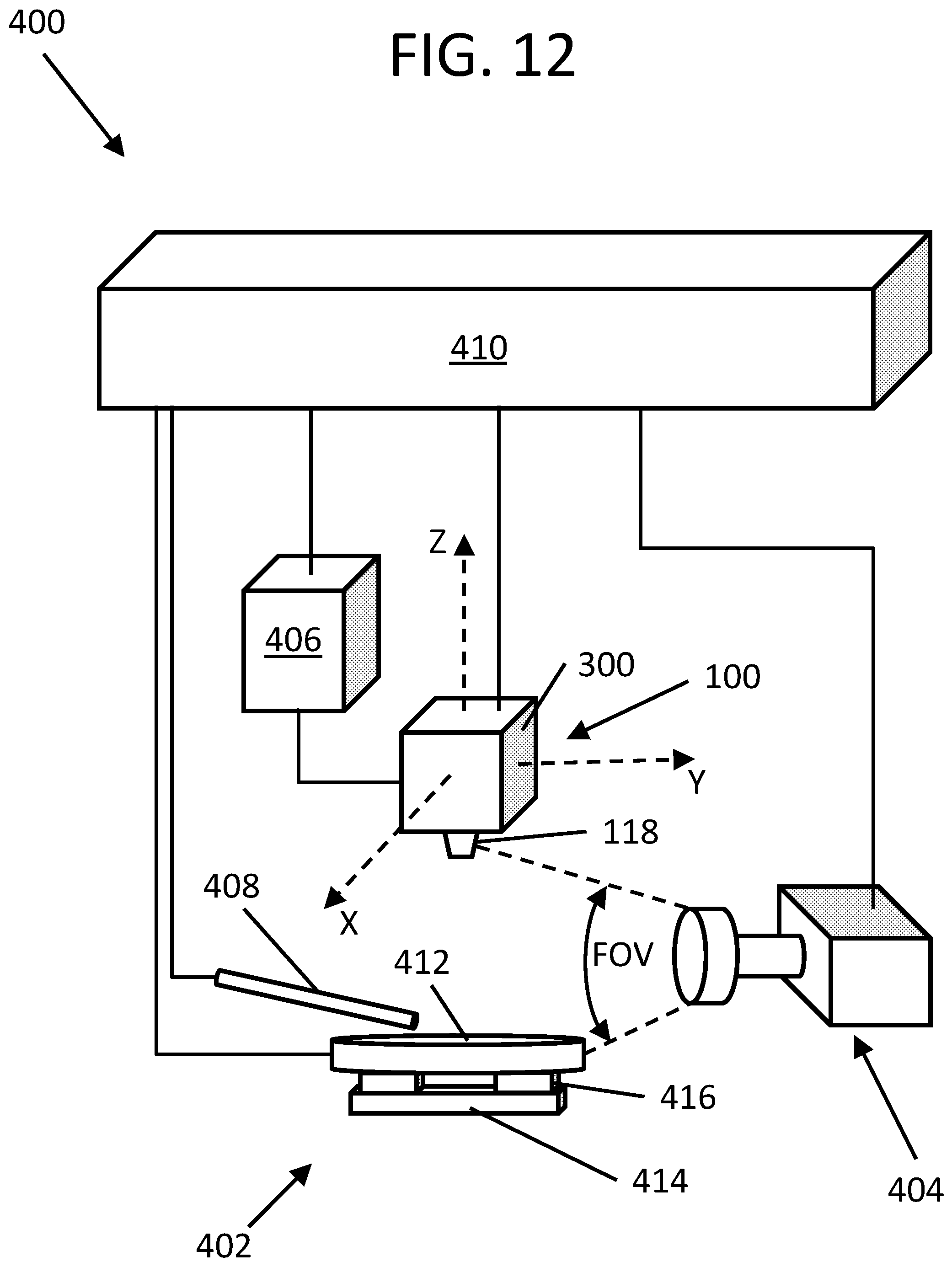
D00013

D00014

D00015

D00016
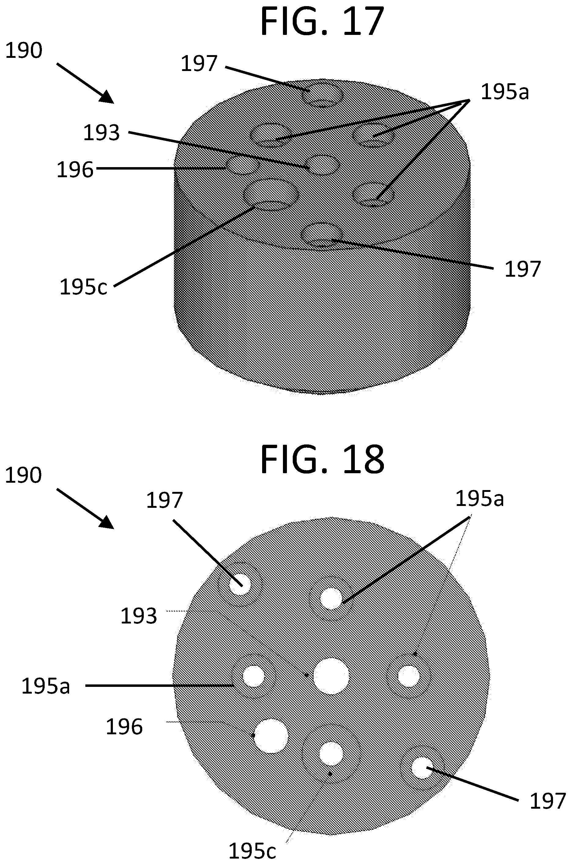
D00017

D00018

D00019
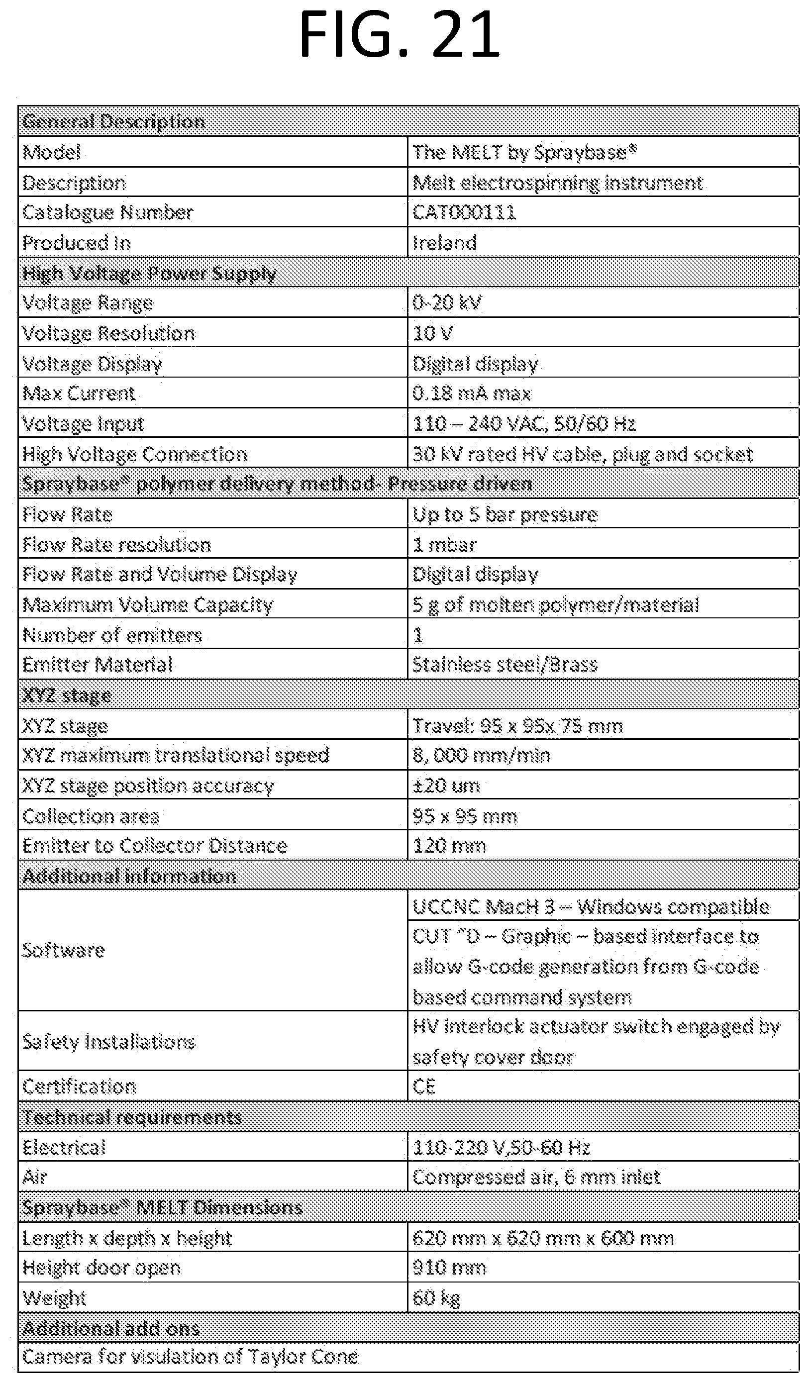
XML
uspto.report is an independent third-party trademark research tool that is not affiliated, endorsed, or sponsored by the United States Patent and Trademark Office (USPTO) or any other governmental organization. The information provided by uspto.report is based on publicly available data at the time of writing and is intended for informational purposes only.
While we strive to provide accurate and up-to-date information, we do not guarantee the accuracy, completeness, reliability, or suitability of the information displayed on this site. The use of this site is at your own risk. Any reliance you place on such information is therefore strictly at your own risk.
All official trademark data, including owner information, should be verified by visiting the official USPTO website at www.uspto.gov. This site is not intended to replace professional legal advice and should not be used as a substitute for consulting with a legal professional who is knowledgeable about trademark law.