Polishing Device
Nakazono; Daisuke ; et al.
U.S. patent application number 16/739178 was filed with the patent office on 2020-07-23 for polishing device. The applicant listed for this patent is HONDA MOTOR CO., LTD.. Invention is credited to Hideaki Imanishi, Daisuke Nakazono, Naoki Takahashi.
| Application Number | 20200230777 16/739178 |
| Document ID | / |
| Family ID | 71608783 |
| Filed Date | 2020-07-23 |


| United States Patent Application | 20200230777 |
| Kind Code | A1 |
| Nakazono; Daisuke ; et al. | July 23, 2020 |
POLISHING DEVICE
Abstract
A polishing device includes shape following sections opposing a workpiece with a polishing body interposed between the shape following sections and the workpiece, and each including a displaceable shaft section. At least two of the shaft sections adjacent to each other are coupled via a link member. For example, when one of the shaft sections of the shape following sections coupled via the link member retracts by receiving a reaction force from the workpiece, the other of the shaft sections advances.
| Inventors: | Nakazono; Daisuke; (Hagagun, JP) ; Takahashi; Naoki; (Hagagun, JP) ; Imanishi; Hideaki; (Hagagun, JP) | ||||||||||
| Applicant: |
|
||||||||||
|---|---|---|---|---|---|---|---|---|---|---|---|
| Family ID: | 71608783 | ||||||||||
| Appl. No.: | 16/739178 | ||||||||||
| Filed: | January 10, 2020 |
| Current U.S. Class: | 1/1 |
| Current CPC Class: | B24B 41/047 20130101; B24B 29/02 20130101 |
| International Class: | B24B 29/02 20060101 B24B029/02; B24B 41/047 20060101 B24B041/047 |
Foreign Application Data
| Date | Code | Application Number |
|---|---|---|
| Jan 21, 2019 | JP | 2019-007418 |
Claims
1. A polishing device that polishes an object-to-be-polished by an expandable or contractible polishing body, the polishing device comprising: a plurality of shape following sections opposing the object-to-be-polished with the polishing body interposed between the shape following sections and the object-to-be-polished, and each including a displaceable shaft section; a supporting body configured to support the shape following sections; and a link section configured to couple the shaft sections to each other, wherein the link section includes a link member configured to couple at least two of the shaft sections adjacent to each other, and when one of the two shaft sections coupled via the link member retracts by receiving a reaction force from the object-to-be-polished, another of the two shaft sections advances.
2. The polishing device according to claim 1, wherein the link section further includes a separate link member configured to couple the link members to each other.
3. The polishing device according to claim 1, wherein the link section is provided with a locking unit configured to position and fix the shaft section.
4. The polishing device according to claim 1, wherein the shape following sections each include a tip that faces the polishing body and is provided with a swinging section configured to swing.
5. The polishing device according to claim 1, wherein the shape following sections each include a tip that faces the polishing body and is configured to rotate.
6. The polishing device according to claim 1, wherein the plurality of shape following sections are arranged in a zigzag manner.
7. The polishing device according to claim 1, further comprising an eccentric rotation unit configured to eccentrically rotate the supporting body.
8. The polishing device according to claim 1, further comprising a robot configured to hold the supporting body.
9. The polishing device according to claim 1, wherein the polishing body is an endless belt configured to turn, and the polishing device comprises a driving force applying unit configured to apply, to the endless belt, a driving force for turning.
Description
CROSS-REFERENCE TO RELATED APPLICATION
[0001] This application is based upon and claims the benefit of priority from Japanese Patent Application No. 2019-007418 filed on Jan. 21, 2019, the contents of which are incorporated herein by reference.
BACKGROUND OF THE INVENTION
Field of the Invention
[0002] The present invention relates to a polishing device that polishes an object-to-be-polished by a polishing body. Description of the Related Art
[0003] A polishing body for polishing an object-to-be-polished is usually configured as a disk-shaped rotating body as exemplified in Japanese Laid-Open Patent Publication No. 2004-009189. However, in this case, although it is possible for a flat surface to be polished, it is not easy for an irregular surface where undulations are present to be uniformly polished.
[0004] Accordingly, providing the polishing body with an elastic body (a cushion), for example, a sponge, is envisioned. This is because in this case, the elastic body is crushed when polishing a projection of the object-to-be-polished, whereas the crushed elastic body attempts to return to its original shape when polishing a recess of the object-to-be-polished. Thus, since a shape following ability is manifested in the polishing body by the elastic body, it is conceivably made possible for the irregular surface to be comparatively easily polished.
SUMMARY OF THE INVENTION
[0005] In fact, the shape following ability of the elastic body is not particularly favorable. Therefore, in the case where, for example, regarding a region-to-be-polished having a complex shape of the kind where a projection and a recess are alternately aligned, it is attempted to polish the projection of the region-to-be-polished, the elastic body may sometimes be insufficiently crushed. When such a situation occurs, a polishing amount with respect to the projection will be larger than a design value.
[0006] In order to avoid this, often, when the region-to-be-polished has a complex shape, polishing is performed manually by an operator. However, this case is troublesome and a burden for the operator.
[0007] A main object of the present invention is to provide a polishing device capable of performing automatic and favorable polishing, even in such a case as when a region-to-be-polished has a complex shape.
[0008] According to an embodiment of the present invention, there is provided a polishing device that polishes an object-to-be-polished by an expandable or contractible polishing body, the polishing device comprising:
[0009] a plurality of shape following sections opposing the object-to-be-polished with the polishing body interposed between the shape following sections and the object-to-be-polished, and each including a displaceable shaft section;
[0010] a supporting body configured to support the shape following sections; and
[0011] a link section configured to couple the shaft sections to each other, wherein
[0012] the link section includes a link member configured to couple at least two of the shaft sections adjacent to each other, and
[0013] when one of the two shaft sections coupled via the link member retracts by receiving a reaction force from the object-to-be-polished, another of the two shaft sections advances.
[0014] In the present invention, when the polishing body makes sliding contact with (performs polishing of) the object-to-be-polished, the shaft section configuring the shape following section that opposes the object-to-be-polished via the polishing body, is displaced. That is, when the shaft section receives the reaction force from the object-to-be-polished, the shaft section retracts in a direction of separating from the object-to-be-polished. Now, the shaft sections adjacent to each other are coupled via the link member. Hence, the shaft section, which is adjacent to the shaft section that has retracted, advances in a direction of approaching the object-to-be-polished. As a result of the adjacent shaft sections being displaced as above, it is avoided that the polishing body receives an excessive pressing force from the shaft sections. It therefore becomes possible for the polishing body to deform in accordance with a shape of the object-to-be-polished.
[0015] That is, according to the present invention, since the shaft section of the shape following section is configured to be displaceable so as to follow the shape of the object-to-be-polished, the polishing body deforms in accordance with the shape of the object-to-be-polished. Therefore, the polishing body makes sliding contact with the region-to-be-polished while applying an appropriate and substantially uniform surface pressure to the region-to-be-polished. This makes it possible for automatic and favorable polishing to be implemented.
[0016] The above and other objects, features, and advantages of the present invention will become more apparent from the following description when taken in conjunction with the accompanying drawings, in which a preferred embodiment of the present invention is shown by way of illustrative example.
BRIEF DESCRIPTION OF THE DRAWINGS
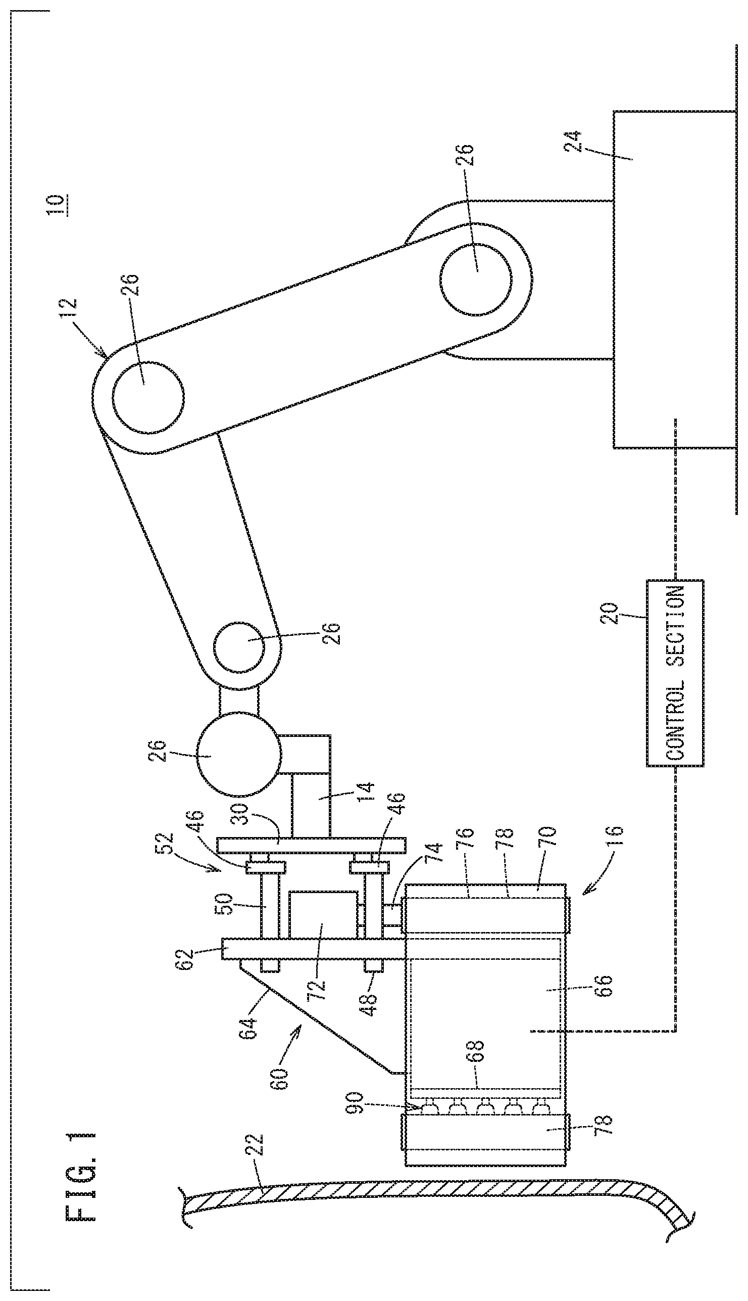
[0017] FIG. 1 is a schematic overall side view of a polishing device according to an embodiment of the present invention;
[0018] FIG. 2 is a schematic side view of a polishing mechanism configuring the polishing device;
[0019] FIG. 3 is a schematic front view of the polishing mechanism;
[0020] FIG. 4 is a schematic plan view of the polishing mechanism;
[0021] FIG. 5 is a schematic partial cross-sectional front view of a shape following mechanism;
[0022] FIG. 6 is a plan view from an endless belt side, of the polishing mechanism;
[0023] FIG. 7 is a schematic front view selectively showing a plurality of the shape following sections;
[0024] FIG. 8 is a schematic explanatory drawing showing a movement locus of the polishing mechanism on a workpiece being an object-to-be-polished; and
[0025] FIG. 9 is a schematic plan view showing one example of attitudes of each of link members included in a link section and a state of displacement of shaft sections, when a recess is present in a region-to-be-polished.
DESCRIPTION OF THE PREFERRED EMBODIMENTS
[0026] A preferred embodiment of a polishing device according to the present invention will be presented and described in detail below with reference to the accompanying drawings.
[0027] FIG. 1 is a schematic overall side view of a polishing device 10 according to the present embodiment. This polishing device 10 comprises: an articulated robot 12; a polishing mechanism 16 provided to a tip arm 14 configuring the articulated robot 12; and a control section 20 that controls the articulated robot 12 and the polishing mechanism 16. Note that the reference symbol 22 in FIG. 1 indicates a workpiece being an object-to-be-polished. An automobile body may be cited as a specific example of the workpiece 22.
[0028] The articulated robot 12 includes a rotatable pedestal 24 and a plurality of operating shafts 26. Hence, the articulated robot 12 is capable of moving the polishing mechanism 16 to a certain place of the workpiece 22, and displacing the polishing mechanism 16 along a region-to-be-polished of the workpiece 22.
[0029] As shown in FIGS. 2 and 3, the polishing mechanism 16 is coupled to the tip arm 14 via a coupling plate 30. A gear holding plate 32 of narrower width and smaller area compared to the coupling plate 30 is close to the coupling plate 30. This gear holding plate 32 is provided with a gear train. Specifically, the gear train includes: a driving gear 38 provided to a driving shaft for eccentricity 36 of a motor for eccentric rotation 34 (an eccentric rotation unit); a first driven gear 40 engaged with the driving gear 38; and a second driven gear 42 engaged with the first driven gear 40. The second driven gear 42 is provided with a driven shaft for eccentricity 44.
[0030] The driving shaft for eccentricity 36 and the driven shaft for eccentricity 44 are passed through shaft insertion holes (not illustrated) respectively formed in the gear holding plate 32 and the coupling plate 30. A first rotating shaft for eccentricity 48 and a second rotating shaft for eccentricity 50 are respectively coupled, via eccentric joints 46, to tips of the driving shaft for eccentricity 36 and the driven shaft for eccentricity 44, the tips being on a side facing the polishing mechanism 16 and projecting from the coupling plate 30. An eccentric rotation mechanism 52 for eccentrically rotating the polishing mechanism 16 is configured as above. Note that an unillustrated bearing is inserted between the shaft insertion hole and the driving shaft for eccentricity 36 or driven shaft for eccentricity 44.
[0031] The first rotating shaft for eccentricity 48 and the second rotating shaft for eccentricity 50 are coupled to a supporting body 60 configuring the polishing mechanism 16. Specifically, as shown in FIGS. 2-4, the supporting body 60 is configured by combining: a motor holding wall section 62 whose height is greatest; a first side wall section 64 that supports a rear surface of the motor holding wall section 62 and has a region that inclines downwardly as the first side wall section 64 is separated from the motor holding wall section 62; a second side wall section 66 whose height is substantially half that of the motor holding wall section 62; and a mechanism holding wall section 68 bridged between the first side wall section 64 and the second side wall section 66. The first rotating shaft for eccentricity 48 and the second rotating shaft for eccentricity 50 are coupled to the upper side of the motor holding wall section 62 among these wall sections. In this case, the first rotating shaft for eccentricity 48 and the second rotating shaft for eccentricity 50 are arranged along a longitudinal direction of the motor holding wall section 62.
[0032] In this way, the tip arm 14 of the articulated robot 12 holds the supporting body 60 configuring the polishing mechanism 16, via the coupling plate 30 and the eccentric rotation mechanism 52. Note that as may be understood from the above, the first side wall section 64 and the second side wall section 66 have their one ends coupled to the motor holding wall section 62 and have their other ends coupled to the mechanism holding wall section 68. The mechanism holding wall section 68 is separated by a predetermined distance from the motor holding wall section 62, by the first side wall section 64 and the second side wall section 66 interposed between the mechanism holding wall section 68 and the motor holding wall section 62.
[0033] As shown in FIG. 2, the motor holding wall section 62 is provided with a motor for turning 72 (a driving force applying unit). The motor for turning 72 applies, to an endless belt 70 (a polishing body) configuring the polishing mechanism 16, a driving force for turning the endless belt 70. The motor for turning 72 is attached to a position not interfering with the first rotating shaft for eccentricity 48 and the second rotating shaft for eccentricity 50, of the motor holding wall section 62. A long columnar driving pulley 76 is fitted over a driving shaft for turning 74 of the motor for turning 72. The driving pulley 76 drives the endless belt 70.
[0034] The supporting body 60 is provided with three bearing sections not illustrated. As shown in FIG. 4, the bearing sections each axially support in a rotatable manner a supporting shaft 80 provided to a long columnar driven pulley 78. Each of side peripheral walls of the driven pulleys 78 also drive the endless belt 70. Due to the driving pulley 76 and the three driven pulleys 78, the endless belt 70 is stretched so as to have a rectangular shape in planar view.
[0035] The endless belt 70 is formed of a stacked body of an inner peripheral belt 82 and an outer peripheral belt 84. The inner peripheral belt 82 is made of a material excelling in wear resistance, and the outer peripheral belt 84 is made of a material excelling in polishing performance. Due to the inner peripheral belt 82 being driven by the driving pulley 76 and the driven pulleys 78, the outer peripheral belt 84 turns integrally with the inner peripheral belt 82. The outer peripheral belt 84 makes sliding contact with the region-to-be-polished of the workpiece 22.
[0036] An exterior tensioner 86 (a tension applying unit) makes sliding contact with the outer peripheral belt 84. The exterior tensioner 86 presses the outer peripheral belt 84 toward the inner peripheral belt 82 side, and thereby applies a tension to the endless belt 70. The larger the pressing force is, the more the endless belt 70 is tensioned. As a result, the tension applied to the endless belt 70 increases. Conversely, when the pressing force is small, the tension applied to the endless belt 70 is reduced.
[0037] The mechanism holding wall section 68 supports a plurality of shape following mechanisms 90 that press the endless belt 70 from the inner peripheral belt 82 side. Next, this shape following mechanism 90 will be described.
[0038] FIG. 5 is a schematic partial cross-sectional front view showing one shape following mechanism 90 along the longitudinal direction thereof. The shape following mechanism 90 includes a shaft section 92 and a swinging section 94.
[0039] The shaft section 92 is configured from a casing of an air motor. The shaft section 92 is held in a displaceable manner by the mechanism holding wall section 68 (refer to FIG. 4), whereby the shape following mechanism 90 is supported by the mechanism holding wall section 68.
[0040] One end on a side of separating from the endless belt 70, of the shaft section 92 is provided with a joint section 96 to which an unillustrated air supplying tube is connected. On the other hand, a rotating shaft 100 is exposed from one end on a side of approaching the endless belt 70. In the shaft section 92, an air release hole 102 is formed in a vicinity of the rotating shaft 100. The rotating shaft 100 rotates as compressed air is supplied to an inside of the shaft section 92 via the air supplying tube and the joint section 96. Compressed air supplied to the shaft section 92 is released to the atmosphere via the air release hole 102.
[0041] The rotating shaft 100 is covered by a coupling shaft 104, and the coupling shaft 104 holds a coupling plate 106. Specifically, the coupling plate 106 has an insertion hole 108 formed therein, and a joint 110 is inserted in the insertion hole 108. The joint 110 has a screw hole formed therein, and a screw section provided to one end of the coupling shaft 104 is screwed into the screw hole. Note that regions exposed from the insertion hole 108, of the joint 110 have screwed onto them a first nut 112 and a second nut 114. Due to this screwing together, dislocation from the insertion hole 108 of the joint 110 is prevented.
[0042] A stepped holder 120 having a step section is attached to the coupling plate 106. A tip of the stepped holder 120 has a screw hole formed therein, and a screw-shaped shaft section 124 of a ball joint 122 is screwed into the screw hole. Moreover, a separable swinging cover 130 is screwed with two engaging shaft sections 128 that project from a ball section 126 of the ball joint 122, and the swinging cover 130 is thereby attached to the engaging shaft sections 128. The swinging cover 130 is configured as a shape closely resembling a spherical segment.
[0043] The coupling shaft 104, the coupling plate 106, the stepped holder 120, the ball joint 122, and the swinging cover 130 rotate integrally as the rotating shaft 100 rotates. In contrast, the shaft section 92 never rotates.
[0044] FIG. 6 is a plan view from the endless belt 70 side. As shown in this FIG. 6, a plurality of the swinging sections 94 are arranged so as to form: a plurality of columns aligned along a turning direction of the endless belt 70: and a plurality of rows aligned along a width direction of the endless belt 70. Moreover, the swinging section 94 (and shaft section 92) of an arbitrary row or column is positioned between swinging sections 94 (and shaft sections 92) of an adjacent row or column. Therefore, the swinging sections 94 (and shaft sections 92) form a zigzag shape overall. Note that in order to facilitate understanding of a zigzag arrangement of the swinging sections 94, a link mechanism 140 is shown only in the single outermost column in FIG. 6.
[0045] Now, FIG. 7 selectively shows a plurality of (in the illustrated example, eight) shape following mechanisms 90 included in an arbitrary column. Hereafter, in order to facilitate differentiation of the individual shape following mechanisms 90, they will be assigned reference symbols 90a-90h.
[0046] As may be understood from FIG. 7, the eight shape following mechanisms 90a-90h are coupled via the link mechanism 140. In more detail, the link mechanism 140 includes first through fourth small link members 142a-142d (link members) that individually couple the adjacent shape following mechanisms 90a, 90b, adjacent shape following mechanisms 90c, 90d, adjacent shape following mechanisms 90e, 90f, and adjacent shape following mechanisms 90g, 90h. The first small link member 142a is coupled via a first tilting shaft 144 to each of the shaft sections 92 of the shape following mechanisms 90a, 90b.
[0047] Similarly, the second small link member 142b is coupled via the first tilting shaft 144 to each of the shaft sections 92 of the shape following mechanisms 90c, 90d, and the third small link member 142c is coupled via the first tilting shaft 144 to each of the shaft sections 92 of the shape following mechanisms 90e, 90f. Furthermore, the fourth small link member 142d is coupled via the first tilting shaft 144 to each of the shaft sections 92 of the shape following mechanisms 90g, 90h.
[0048] A first medium link member 146a (a separate link member) is arranged on an outer side of the first small link member 142a and the second small link member 142b. Intermediate sections in a longitudinal direction of the first small link member 142a and the second small link member 142b and each of end sections of the first medium link member 146a are coupled via second tilting shafts 148. It is possible for the first small link member 142a and the second small link member 142b to individually tilt with the second tilting shafts 148 as fulcrums.
[0049] A second medium link member 146b (a separate link member) arranged on an outer side of the third small link member 142c and the fourth small link member 142d also similarly has each of its end sections coupled to intermediate sections in a longitudinal direction of the third small link member 142c and the fourth small link member 142d via the second tilting shafts 148. It is therefore possible for the third small link member 142c and the fourth small link member 142d to individually tilt with the second tilting shafts 148 as fulcrums.
[0050] Furthermore, a large link member 150 (a separate link member) is arranged on an outer side of the first medium link member 146a and the second medium link member 146b. Intermediate sections in a longitudinal direction of the first medium link member 146a and the second medium link member 146b and each of end sections of the large link member 150 are coupled via third tilting shafts 152. That is, it is possible for the first medium link member 146a and the second medium link member 146b to individually tilt with the third tilting shafts 152 as fulcrums.
[0051] The first tilting shafts 144, the second tilting shafts 148, and the third tilting shafts 152 are individually provided with unillustrated electromagnets. When the electromagnet is energized under control action of the control section 20, the first tilting shaft 144, the second tilting shaft 148, or the third tilting shaft 152 is restrained by an electromagnetic force. That is, rotation of each of the tilting shafts 144, 148, 152 is forcibly stopped. As a result, tilting of the first through fourth small link members 142a-142d, the first medium link member 146a, the second medium link member 146b, and the large link member 150 is forcibly stopped. Thus, the electromagnet is a locking unit for restraining the first tilting shaft 144, the second tilting shaft 148, or the third tilting shaft 152.
[0052] Contrarily, when energization of the electromagnet is stopped, the first tilting shaft 144, the second tilting shaft 148, or the third tilting shaft 152 is released from restraint of the electromagnetic force to become rotatable. Hence, the first through fourth small link members 142a-142d, the first medium link member 146a, the second medium link member 146b, and the large link member 150 attain a tiltable state.
[0053] Although illustration thereof is omitted, when eight or more shape following mechanisms 90 are included in one column, the link mechanism 140 similar to that described above is provided also to the remaining shape following mechanisms 90. Moreover, the same applies also to another column. Note that the link mechanism 140 is not provided between an arbitrary single shape following mechanism 90 and a shape following mechanism 90 included in a row adjacent to this arbitrary single shape following mechanism 90.
[0054] In the above configuration, the control section 20 controls the motor for eccentric rotation 34, the motor for turning 72, the exterior tensioner 86, the electromagnets, and an air supplying mechanism (not illustrated) for performing supply/discharge of compressed air to/from the air motor.
[0055] The polishing device 10 according to the present embodiment is basically configured as above, and the operational advantages thereof will be next described in relation to a control method (operation) of the polishing device 10.
[0056] In order to move the endless belt 70 along the region-to-be-polished in a state where the endless belt 70 has been abutted on a polishing start point of the workpiece 22, teaching is performed beforehand in the articulated robot 12 so that each of the shafts rotates or revolves by a predetermined angle. In addition, the control section 20 selects the shape following mechanisms 90 that should be supplied with compressed air from the air supplying mechanism from among the plurality of shape following mechanisms 90 based on a shape of the workpiece 22, and determines a timing of that supply.
[0057] For example, when implementing polishing on the workpiece 22 shown in FIG. 8, the polishing mechanism 16 is displaced in order of a section-A 160.fwdarw.a section-B 162.fwdarw.a section-C 164.fwdarw.a section-D 166 of the workpiece 22. That is, the section-A 160 is the polishing start point, and the section-D 166 is a polishing end point. In the case where, for example, in the section-A 160, one column, namely, a lowest column, in the section-B 162 and the section-C 164, two columns, namely, the lowest column and a column one above the lowest column, and in the section-D 166, three columns, namely, the lowest column and columns one and two above the lowest column, fall outside the region-to-be-polished, the lowest column does not overlap the region-to-be-polished from the polishing start point to the polishing end point. In such a case, compressed air may not be supplied to the shaft sections 92 of the shape following mechanisms 90 forming the lowest column.
[0058] When starting polishing, the control section 20 first controls the exterior tensioner 86. Specifically, the exterior tensioner 86 is displaced so as to approach the endless belt 70, and presses the endless belt 70. Due to this pressing, the endless belt 70 is tensioned so that the tension thereof increases. In addition, the control section 20 supplies compressed air from the air supplying mechanism. The compressed air is introduced into the shaft section 92 (the casing) via the air supplying tube and the joint section 96. As a result, the rotating shaft 100 configuring the air motor rotates, and, moreover, the coupling shaft 104, the coupling plate 106, the stepped holder 120, the ball joint 122, and the swinging cover 130 integrally rotate.
[0059] After the operating shafts 26 of the articulated robot 12 have each suitably operated, and the endless belt 70 has abutted on the section-A 160, the control section 20 drives the motor for eccentric rotation 34 and the motor for turning 72. In association with the rotation of the driving shaft for eccentricity 36 of the motor for eccentric rotation 34, the driving gear 38 rotates, and the first driven gear 40 (refer to FIGS. 2 and 3) engaged with the driving gear 38 and the second driven gear 42 engaged with the first driven gear 40, rotate. Following this, the driven shaft for eccentricity 44 also rotates.
[0060] As described above, the first rotating shaft for eccentricity 48 and the second rotating shaft for eccentricity 50 are respectively coupled, via the eccentric joints 46, to the driving shaft for eccentricity 36 and the driven shaft for eccentricity 44. Hence, the first rotating shaft for eccentricity 48 and the second rotating shaft for eccentricity 50 move with loci of circles centered on respective rotation centers of the driving shaft for eccentricity 36 and the driven shaft for eccentricity 44. As a result, the polishing mechanism 16, in which the first rotating shaft for eccentricity 48 and the second rotating shaft for eccentricity 50 are coupled to the supporting body 60, eccentrically rotates.
[0061] Moreover, when the motor for turning 72 is driven, the driving shaft for turning 74 and the driving pulley 76 (refer to FIG. 4) rotate. Therefore, the endless belt 70 pulled by the driving pulley 76 begins to turn. Turning of the endless belt 70 is assisted by the three driven pulleys 78. That is, in this case, the endless belt 70 turns due to the driving pulley 76 and the three driven pulleys 78, while being applied with tension by the exterior tensioner 86 and being pressed by the shape following mechanism 90 (the swinging cover 130) from the inner peripheral belt 82 side.
[0062] Due to the above eccentric rotation of the polishing mechanism 16 and turning of the endless belt 70, polishing of the section-A 160 is started. That is, the endless belt 70 makes sliding contact with the section-A 160, thereby polishing the section-A 160. Since the swinging cover 130 which is rotating is abutting on the endless belt 70, the endless belt 70 receives a pressing force from the shape following mechanism 90 to be pressed against the section-A 160. Moreover, the endless belt 70 makes sliding contact over the section-A 160 with sufficient surface pressure, while eccentrically rotating integrally with the supporting body 60. By a combination of rotation of the swinging cover 130 and turning and eccentric rotation of the endless belt 70, the section-A 160 is favorably polished.
[0063] Moreover, the plurality of shape following mechanisms 90 are disposed in a zigzag manner. In this case, the plurality of shape following mechanisms 90 come close to each other more densely compared to when the shape following mechanisms 90 are disposed on the same axis. Hence, the section-A 160 (the region-to-be-polished) can be evenly polished. Thus, the shape following mechanisms 90 disposed in a zigzag manner complement each other's range of polishing.
[0064] In this state, the control section 20 operates each of the operating shafts 26 of the articulated robot 12 in such a manner that the polishing mechanism 16 moves to the section-D 166 through the section-B 162 and the section-C 164. Note that in the course of the polishing mechanism 16 moving, the shaft sections 92 of the shape following mechanisms 90 positioned outside the region-to-be-polished do not undergo supply of compressed air.
[0065] Incidentally, projections 170a, 170b or a recess 172 sunken relatively with respect to the projections 170a, 170b are assumed to be present in the workpiece 22, as shown in FIG. 9. In this case, the shape following mechanisms 90b, 90c, 90e, 90f, 90g positioned above the projections 170a, 170b receive a reaction force from the projections 170a, 170b to be displaced in a direction of separating from the projections 170a, 170b.
[0066] At this time, the first through fourth small link members 142a-142d tilt with the first tilting shafts 144 as fulcrums, and, depending on a degree of protrusion of the projections 170a, 170b, the second medium link member 146b tilts with the second tilting shafts 148 as fulcrums. Furthermore, the large link member 150 tilts with the third tilting shafts 152 as fulcrums. Due to this tilting, the shape following mechanisms 90a, 90d, 90h opposing the recess 172 are displaced in a direction of approaching the recess 172.
[0067] Moreover, the swinging covers 130 configuring the shape following mechanisms 90a-90h swing in accordance with the shape of the region-to-be-polished or inclination angles of the projections 170a, 170b. For the above reason, abutting on the endless belt 70, of the swinging covers 130 configuring the shape following mechanisms 90a-90h is maintained, regardless of the shape of the workpiece 22 or the inclination angles of the projections 170a, 170b. Therefore, deformation of the endless belt 70 is never hindered. Hence, the region-to-be-polished can be favorably polished, regardless of the shape of the region-to-be-polished.
[0068] Thus, in the present embodiment, the first through fourth small link members 142a-142d, the first medium link member 146a, the second medium link member 146b, and the large link member 150 that configure the link mechanism 140 suitably tilt in accordance with the shape of the workpiece 22 from the polishing start point (the section-A 160) to the polishing end point (the section-D 166). Due to this tilting, the shaft section 92 configuring the shape following mechanism 90 is displaced in a direction of approaching the workpiece 22 or in a direction of separating from the workpiece 22. As a result, the endless belt 70 changes following the shape of the workpiece 22. Hence, polishing of the workpiece 22 by the polishing mechanism 16 can be favorably continued. Note that when a place not requiring polishing is present even in the region-to-be-polished, those of the shape following mechanisms 90 that oppose the place not requiring polishing may not be supplied with compressed air.
[0069] For example, when the projections 170a, 170b and the recess 172 are present over a long distance, the shaft sections 92 may be positioned and fixed. In this case, the control section 20 performs energization of the electromagnets provided to each of the first tilting shafts 144, the second tilting shafts 148, and the third tilting shafts 152. As described above, restraint of the electromagnetic force generated along with this energization hinders further rotation of the first tilting shafts 144, the second tilting shafts 148, and the third tilting shafts 152, and, consequently, further tilting of the first through fourth small link members 142a-142d, the first medium link member 146a, the second medium link member 146b, and the large link member 150. Hence, the shaft sections 92 are brought into a locked state of being positioned and fixed. In other words, positions of the shaft sections 92 become constant. Since, as a result, a state of the swinging covers 130 having abutted on the endless belt 70 is maintained, the workpiece 22 can be favorably polished.
[0070] In order to release the locked state, energization of the electromagnets should be stopped. The electromagnetic force thereby disappears, so each of the first tilting shafts 144, the second tilting shafts 148, and the third tilting shafts 152 is released from restraint of the electromagnetic force to become rotatable. As a result, the first through fourth small link members 142a-142d, the first medium link member 146a, the second medium link member 146b, and the large link member 150 become tiltable.
[0071] There is no particular need for locking by the electromagnet to be performed simultaneously on all of the first tilting shafts 144, the second tilting shafts 148, and the third tilting shafts 152. That is, only the electromagnets provided to tilting shifts needing to be locked should undergo energization and be activated.
[0072] Although FIG. 9 shows the projections 170a, 170b or recess 172 in an exaggerated manner, the actual degree of protrusion of the projections 170a, 170b is at most several tens of micrometers, and a depth of the recess 172 is also of the same degree.
[0073] When the polishing mechanism 16 reaches the section-D 166, rotation or revolution of each of the operating shafts 26 of the articulated robot 12 stops, and movement of the polishing mechanism 16 ends. At this time, the control section 20 stops both the motor for eccentric rotation 34 and the motor for turning 72, whereby eccentric rotation of the polishing mechanism 16 and turning of the endless belt 70 are stopped.
[0074] As indicated above, according to the present embodiment, polishing can be performed automatically by the polishing device 10. Therefore, a burden of the operator is reduced.
[0075] Moreover, as described above, the endless belt 70 is turning, so an unspecific place of the outer peripheral belt 84 makes sliding contact with the region-to-be-polished. In other words, it is avoided that a specific place alone of the outer peripheral belt 84 is involved in polishing. Therefore, the outer peripheral belt 84 is not easily worn down. Hence, the same outer peripheral belt 84 can be employed over a long time, even when the above-described polishing is repeated. Note that when the outer peripheral belt 84 has worn down due to repeated polishing over a long time, and polishing accuracy has lowered, the outer peripheral belt 84 should be replaced with a new one.
[0076] The present invention is not particularly limited to the above-described embodiment, and may be variously modified in a range not departing from the spirit of the present invention.
[0077] For example, a sheet body may be stretched to configure the polishing body, instead of the endless belt 70.
[0078] Furthermore, polishing may be performed similarly to above except that the motor for eccentric rotation 34 is not operated (in other words, except that the polishing mechanism 16 is not eccentrically rotated). Also in this case, sufficient polishing is performed. As may be understood from this, the eccentric rotation unit, such as the motor for eccentric rotation 34, is not indispensable.
[0079] Moreover, a link mechanism omitting any of the first medium link member 146a, the second medium link member 146b, or the large link member 150, may be provided. When the large link member 150 is present in plurality, a further separate link member coupling these large link members 150 may be provided.
* * * * *
D00000
D00001
D00002
D00003
D00004
D00005
D00006
D00007
D00008
D00009
XML
uspto.report is an independent third-party trademark research tool that is not affiliated, endorsed, or sponsored by the United States Patent and Trademark Office (USPTO) or any other governmental organization. The information provided by uspto.report is based on publicly available data at the time of writing and is intended for informational purposes only.
While we strive to provide accurate and up-to-date information, we do not guarantee the accuracy, completeness, reliability, or suitability of the information displayed on this site. The use of this site is at your own risk. Any reliance you place on such information is therefore strictly at your own risk.
All official trademark data, including owner information, should be verified by visiting the official USPTO website at www.uspto.gov. This site is not intended to replace professional legal advice and should not be used as a substitute for consulting with a legal professional who is knowledgeable about trademark law.