Electric Blower, Vacuum Cleaner, And Hand Drying Device
TSUCHIDA; Kazuchika ; et al.
U.S. patent application number 16/486891 was filed with the patent office on 2020-07-23 for electric blower, vacuum cleaner, and hand drying device. The applicant listed for this patent is Mitsubishi Electric Corporation. Invention is credited to Naho ADACHI, Kazuchika TSUCHIDA.
| Application Number | 20200229660 16/486891 |
| Document ID | / |
| Family ID | 63855698 |
| Filed Date | 2020-07-23 |


| United States Patent Application | 20200229660 |
| Kind Code | A1 |
| TSUCHIDA; Kazuchika ; et al. | July 23, 2020 |
ELECTRIC BLOWER, VACUUM CLEANER, AND HAND DRYING DEVICE
Abstract
An electric blower includes a motor, a first rotor blade provided on one end side of the motor in an axial direction, a second rotor blade provided on another side of the motor opposite to the first rotor blade in the axial direction, and a first stator blade provided to face the first rotor blade.
| Inventors: | TSUCHIDA; Kazuchika; (Tokyo, JP) ; ADACHI; Naho; (Tokyo, JP) | ||||||||||
| Applicant: |
|
||||||||||
|---|---|---|---|---|---|---|---|---|---|---|---|
| Family ID: | 63855698 | ||||||||||
| Appl. No.: | 16/486891 | ||||||||||
| Filed: | April 19, 2017 | ||||||||||
| PCT Filed: | April 19, 2017 | ||||||||||
| PCT NO: | PCT/JP2017/015655 | ||||||||||
| 371 Date: | August 19, 2019 |
| Current U.S. Class: | 1/1 |
| Current CPC Class: | A47K 10/48 20130101; F04D 25/08 20130101; F04D 25/082 20130101; F04D 25/166 20130101; F04D 29/281 20130101; F04D 29/051 20130101; F04D 29/444 20130101; F04D 29/424 20130101; F04D 25/06 20130101; A47L 5/22 20130101; F04D 29/056 20130101; F04D 29/5806 20130101 |
| International Class: | A47K 10/48 20060101 A47K010/48; A47L 5/22 20060101 A47L005/22 |
Claims
1. An electric blower comprising: a motor: a first rotor blade provided on one end side of the motor in an axial direction; a second rotor blade provided on another side of the motor opposite to the first rotor blade in the axial direction; a first stator blade provided to face the first rotor blade; and a second stator blade provided to face the second rotor blade.
2. The electric blower according to claim 1, wherein the first stator blade includes: a first main plate having a first surface and a second surface that is a surface on a side opposite to the first surface; and a vane formed on the first surface and to regulate an air current generated by rotation of the first rotor blade.
3. The electric blower according to claim 2, further comprising a first wind guide plate provided between the first stator blade and the motor and to guide an air current generated by the rotation of the first rotor blade towards the motor.
4. The electric blower according to claim 1, wherein the first stator blade includes: a first main plate having a first surface and a second surface that is a surface on a side opposite to the first surface; and a plurality of vanes formed on the first surface and to regulate an air current generated by rotation of the first rotor blade, and the plurality of vanes are arranged in a radial pattern around a rotation center of the first rotor blade.
5. The electric blower according to claim 1, wherein the second stator blade includes: a second main plate having a third surface and a fourth surface that is a surface on a side opposite to the third surface; and a vane formed on the third surface and to regulate an air current generated by rotation of the second rotor blade.
6. The electric blower according to claim 5, further comprising a second wind guide plate provided between the second stator blade and the motor and to guide an air current generated by the rotation of the second rotor blade towards the motor.
7. The electric blower according to claim 1, wherein the motor includes: a rotor; and a shaft fixed to the rotor and to rotate the first rotor blade and the second rotor blade.
8. The electric blower according to claim 7, wherein the motor includes a motor frame covering the rotor, and the motor frame has holes formed on both sides in the axial direction, the holes passing through the motor frame in the axial direction.
9. The electric blower according to claim 8, wherein the motor frame has holes formed on both sides of the motor in a radial direction, the holes passing through the motor frame in the radial direction.
10. The electric blower according to claim 1, further comprising a casing covering the first rotor blade and the second rotor blade, wherein the casing has: a first intake formed to face the first rotor blade; a second intake formed to face the second rotor blade; and an outlet formed to face the motor.
11. A vacuum cleaner comprising: a dust collection part; and an electric blower to generate suction power and send dust to the dust collection part, wherein the electric blower includes: a motor: a first rotor blade provided on one end side of the motor in an axial direction; a second rotor blade provided on another side of the motor opposite to the first rotor blade in the axial direction; a first stator blade provided to face the first rotor blade; and a second stator blade provided to face the second rotor blade.
12. A hand drying device comprising: a casing having an air intake and an air outlet; and an electric blower that is fixed inside the casing, the electric blower sucking in air exterior to the casing through the air intake and sending the air outside the casing through the air outlet, wherein the electric blower includes: a motor: a first rotor blade provided on one end side of the motor in an axial direction; a second rotor blade provided on another side of the motor opposite to the first rotor blade in the axial direction; a first stator blade provided to face the first rotor blade; and a second stator blade provided to face the second rotor blade.
Description
CROSS REFERENCE TO RELATED APPLICATION
[0001] This application is a U.S. national stage application of International Patent Application No. PCT/JP2017/015655 filed on Apr. 19, 2017, the disclosure of which is incorporated herein by reference.
TECHNICAL FIELD
[0002] The present invention relates to an electric blower including a motor.
BACKGROUND
[0003] An electric blower formed of a casing, a motor disposed inside the casing, and a blade part (e.g., rotor blade) fixed to a shaft of the motor is generally used. In this type of electric blower, when the motor and the blade part are rotating, air flows into the casing through an intake formed in the casing and the air is discharged outside the casing through an outlet formed in the casing (see Patent Reference 1, for example).
PATENT REFERENCE
[0004] Patent Reference 1: Japanese Patent Application Publication No. 2013-44435
[0005] However, when air flows into the electric blower through the intake while the motor is driving, thrust force occurs in the shaft of the motor and the blade part due to pressure difference between the intake side and the outlet side. Due to the thrust force, a thrust load occurs in the motor. For example, in a case where the shaft is supported by a bearing, friction occurs between an inner ring and an outer ring of the bearing. As a result, a problem arises in that the operating life of the bearing decreases and the operating life of the electric blower decreases.
SUMMARY
[0006] An object of the present invention is to reduce the thrust load acting on the motor when the rotor blade rotates and prevent the decrease in the operating life of the electric blower.
[0007] An electric blower according to the present invention includes a motor, a first rotor blade provided on one end side of the motor in an axial direction, a second rotor blade provided on another side of the motor opposite to the first rotor blade in the axial direction, a first stator blade provided to face the first rotor blade, and a second stator blade provided to face the second rotor blade.
[0008] According to the present invention, the thrust load acting on the motor can be reduced and the decrease in the operating life of the electric blower can be prevented.
BRIEF DESCRIPTION OF THE DRAWINGS
[0009] FIG. 1 is a cross-sectional view schematically showing a structure of an electric blower according to a first embodiment of the present invention.
[0010] FIG. 2a is a cross-sectional view schematically showing the structure of the electric blower.
[0011] FIG. 2b is a cross-sectional view schematically showing another structure of the electric blower shown in FIG. 1 and FIG. 2a.
[0012] FIG. 3a is a perspective view schematically showing a structure of a mixed flow fan as a rotor blade.
[0013] FIG. 3b is a perspective view schematically showing a structure of a turbo fan as the rotor blade.
[0014] FIG. 4a is a plan view schematically showing a structure of a stator blade.
[0015] FIG. 4b is a cross-sectional view taken along a line 4b-4b in FIG. 4a.
[0016] FIG. 4c is a plan view schematically showing another structure of the stator blade.
[0017] FIG. 4d is a cross-sectional view taken along a line 4b-4b in FIG. 4c.
[0018] FIG. 5 is a diagram showing a flow of air in the electric blower when the electric blower is driven.
[0019] FIG. 6 is a diagram showing the flow of air in the electric blower when the electric blower is driven.
[0020] FIG. 7 is a cross-sectional view schematically showing a structure of an electric blower according to a comparative example.
[0021] FIG. 8 is a cross-sectional view schematically showing a structure of an electric blower according to a second embodiment of the present invention.
[0022] FIG. 9 is a diagram showing a flow of air in the electric blower when the electric blower is driven.
[0023] FIG. 10 is a side view schematically showing a vacuum cleaner according to a third embodiment of the present invention.
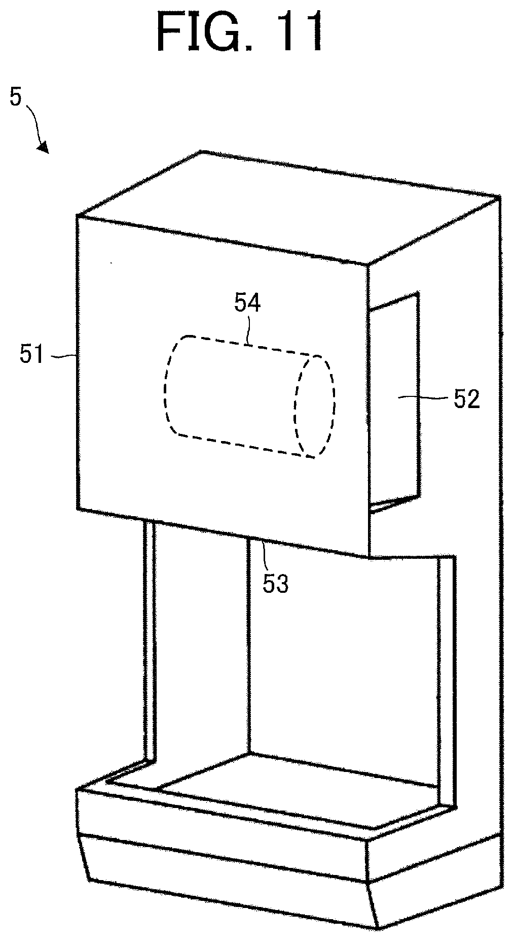
[0024] FIG. 11 is a perspective view schematically showing a hand drier as a hand drying device according to a fourth embodiment of the present invention.
DETAILED DESCRIPTION
First Embodiment
[0025] FIG. 1 and FIG. 2a are cross-sectional views schematically showing a structure of an electric blower 1 according to a first embodiment of the present invention. Specifically, FIG. 2a is a diagram showing a state in which the electric blower 1 shown in FIG. 1 is rotated in a circumferential direction. The "circumferential direction" is the direction of rotation of a rotor blade 21a, for example. FIG. 2b is a diagram showing another example of the electric blower 1 shown in FIG. 1 and FIG. 2a. The cross section position of the electric blower 1 in FIG. 2b is the same as the cross section position of the electric blower 1 in FIG. 2a.
[0026] In the xyz orthogonal coordinate system shown in FIG. 1, a z-axis direction (z-axis) represents a direction parallel to an axis line of a shaft 14 of a motor 10 (rotation center of a rotor 13) (hereinafter referred to as an "axial direction"), an x-axis direction (x-axis) represents a direction orthogonal to the z-axis direction (z-axis), and a y-axis direction represents a direction orthogonal to both of the z-axis direction and the x-axis direction.
[0027] The electric blower 1 includes the motor 10, the rotor blade 21a (first rotor blade), a rotor blade 21b (second rotor blade), a stator blade 22a (first stator blade), a stator blade 22b (second stator blade), and a casing 30.
[0028] The motor 10 is a permanent magnet synchronous motor, for example. However, it is also possible to use a motor other than a permanent magnet synchronous motor, such as a commutator motor, as the motor 10. The permanent magnet synchronous motor means a synchronous motor including a permanent magnet (ferromagnetic body) and using the permanent magnet (ferromagnetic body) for generating a magnetic field.
[0029] The motor 10 includes a motor frame 11 (also referred to simply as a "frame"), a stator 12 fixed to the motor frame 11, the rotor 13 disposed inside the stator 12, the shaft 14 fixed to the rotor 13, bearings 15a and 15b supporting the shaft 14, nuts 16a and 16b, and a bracket 17 that is a part of the motor frame 11. The shaft 14 is press-fitted in the bearings 15a and 15b.
[0030] The bearing 15a (specifically, an outer circumferential surface of the bearing 15a) is fixed to an inner circumferential surface of the motor frame 11. The bearing 15b (specifically, an outer circumferential surface of the bearing 15b) is fixed to an inner circumferential surface of the bracket 17.
[0031] The motor frame 11 covers the stator 12 and the rotor 13. The motor frame 11 has holes (windholes) 11a and 11b (FIG. 2a). In this embodiment, a plurality of holes 11a and a plurality of holes 11b are formed respectively on both sides of the motor frame 11 in the axial direction. Specifically, the holes 11b are formed in the bracket 17 that is a part of the motor frame 11. Each hole 11a, 11b passes through the motor frame 11 in the axial direction.
[0032] The casing 30 covers the rotor blades 21a and 21b and the stator blades 22a and 22b. The casing 30 includes fan covers 30a each covering the rotor blade (rotor blade 21a or 21b), fan cover support parts 30b supporting the fan covers 30a, an intake 31a (first intake), an intake 31b (second intake), an outlet 32a (first outlet), and an outlet 32b (second outlet).
[0033] The fan cover 30a is inserted in the fan cover support part 30b, and the fan cover support part 30b is fixed to the motor frame 11 or the bracket 17.
[0034] The intake 31a is formed in the casing 30 to face the rotor blade 21a, while the intake 31b is formed in the casing 30 to face the rotor blade 21b.
[0035] The outlets 32a and 32b are formed in the casing 30 to face the motor 10.
[0036] FIGS. 3a and 3b are perspective views showing examples of the rotor blade 21a. The rotor blades shown in FIGS. 3a and 3b are usable also as the rotor blade 21b.
[0037] FIG. 3a is a perspective view schematically showing a structure of a mixed flow fan as a centrifugal fan used as the rotor blade. The mixed flow fan is a fan that generates an air current in a direction inclined with respect to the rotation axis of the rotor blade. FIG. 3b is a perspective view schematically showing a structure of a turbo fan as a centrifugal fan used as the rotor blade. The turbo fan is a fan having vanes formed backward. However, the rotor blades 21a and 21b may be fans other than mixed flow fans or turbo fans.
[0038] The rotor blades 21a and 21b are desired to be rotor blades (e.g., mixed flow fans or turbo fans) having the same structure as each other so that the thrust loads acting on the rotor blades 21a and 21b are equal to each other.
[0039] The rotor blade 21a is provided on one end side of the motor 10 in the axial direction, while the rotor blade 21b is provided on another side opposite to the rotor blade 21a in the axial direction. The rotor blades 21a and 21b are respectively fixed to the shaft 14 by the nuts 16a and 16b, and the shaft 14 rotates the rotor blades 21a and 21b. Specifically, the rotor blades 21a and 21b rotate in accordance with the rotation of the motor 10 (specifically, the rotor 13 and the shaft 14). Accordingly, the rotor blades 21a and 21b generate air currents.
[0040] Screw threads at both ends of the shaft 14 are formed to be in directions symmetrical with each other. With this configuration, inertial force occurring when the motor 10 stops is transmitted to the nuts 16a and 16b and loosening of the nuts 16a and 16b can be inhibited.
[0041] FIG. 4a is a plan view schematically showing a structure of the stator blade 22a.
[0042] FIG. 4b is a cross-sectional view taken along a line 4b-4b in FIG. 4a.
[0043] FIG. 4c is a plan view schematically showing another structure around the stator blade 22a.
[0044] FIG. 4d is a cross-sectional view taken along a line 4b-4b in FIG. 4c.
[0045] As shown in FIGS. 4a and 4b, the stator blade 22a includes a main plate 23a, at least one vane 26a, and a shaft hole 29a in which the shaft 14 is inserted. The stator blade 22a is provided to face the rotor blade 21a. In the example shown in FIG. 1, the stator blade 22a is fixed to the motor frame 11, while the stator blade 22b is fixed to the bracket 17. At least one wind guide plate 27a (first wind guide plate) is provided between the stator blade 22a and the motor 10.
[0046] The vane 26a regulates an air current generated by the rotation of the rotor blade 21a (e.g., direction of the air current). The wind guide plate 27a guides the air current generated by the rotation of the rotor blade 21a towards the motor 10.
[0047] The main plate 23a has a first surface 24a as a front side and a second surface 25a as a back side. The stator blade 22a is fixed to the casing 30 so that the first surface 24a faces the rotor blade 21a. That is, the first surface 24a faces the rotor blade 21a and the second surface 25a is a surface on the side opposite to the first surface 24a.
[0048] In this embodiment, a plurality of vanes 26a are formed on the first surface 24a and a plurality of wind guide plates 27a are formed on the second surface 25a. The plurality of vanes 26a and the plurality of wind guide plates 27a are arranged in spiral patterns to be in phases opposite to each other.
[0049] The structure shown in FIGS. 4c and 4d may be employed instead of the structure shown in FIGS. 4a and 4b. The electric blower having the structure shown in FIGS. 4c and 4d corresponds to the electric blower 1 shown in FIG. 2b. The stator blade 22a shown in FIGS. 4c and 4d includes at least one vane 26a, a shaft hole 29a in which the shaft 14 is inserted, and two fixation holes 29b. In the structure shown in FIGS. 4c and 4d, similarly to the structure shown in FIGS. 4a and 4b, at least one wind guide plate 27a (first wind guide plate) is provided between the stator blade 22a and the motor 10.
[0050] In the example shown in FIGS. 4c and 4d, the wind guide plate 27a is formed not on the main plate 23a of the stator blade 22b but on a main plate 27. A shaft hole 29a, two fixation holes 29b, and a frame insertion hole 29c in which an end of the motor frame 11 in the axial direction is inserted are formed in the main plate 27. The fixation holes 29b that are two through holes are formed in the main plate 23a and the main plate 27, and the main plate 23a and the main plate 27 can be fixed together by putting fixation members through the fixation holes 29b. However, it is also possible to fix the main plate 23a and the main plate 27 together by using an adhesive agent or the like without forming the fixation holes 29b in the main plate 23a and the main plate 27. By separately molding the main plate 23a provided with the vane 26a and the main plate 27 provided with the wind guide plate 27a, the structure of the mold is simplified and the molding is facilitated in comparison with the structure in which these parts are integrated together (i.e., the structure shown in FIGS. 4a and 4b).
[0051] The stator blade 22b includes a main plate 23b and at least one vane 26b. The stator blade 22b is provided to face the rotor blade 21b. In this embodiment, the stator blade 22b has no wind guide plate. In this embodiment, the stator blade 22b has the same structure as the stator blade 22a except for the wind guide plate. That is, the main plate 23b corresponds to the main plate 23a shown in FIGS. 4a and 4b, and the vane 26b corresponds to the vane 26a shown in FIGS. 4a and 4b.
[0052] The vane 26b regulates an air current generated by the rotation of the rotor blade 21b (e.g., direction of the air current).
[0053] The main plate 23b has a third surface 24b as a front side and a fourth surface 25b as a back side (FIG. 2a). The stator blade 22b is fixed to the casing 30 so that the third surface 24b faces the rotor blade 21b. That is, the third surface 24b faces the rotor blade 21b and the fourth surface 25b is a surface on the side opposite to the third surface 24b. In this embodiment, a plurality of vanes 26b are formed on the third surface 24b.
[0054] As shown in FIG. 4a, the stator blade 22a (specifically, the main plate 23a) is in a circular shape, and the plurality of vanes 26a are arranged in the circumferential direction of the stator blade 22a (specifically, the main plate 23a) and arranged in a radial pattern around the rotation center of the rotor blade 21a. On the stator blade 22b, the plurality of vanes 26b are arranged similarly to the plurality of vanes 26a.
[0055] As shown in FIG. 4a, the plurality of wind guide plates 27a are arranged in the circumferential direction of the stator blade 22a (specifically, the main plate 23a) and arranged in a radial pattern around the rotation center of the rotor blade 21a.
[0056] FIG. 5 and FIG. 6 are diagrams showing a flow of air in the electric blower 1 when the electric blower 1 is driven.
[0057] As shown in FIG. 5, while the motor 10 is driving, the rotor 13 and the shaft 14 rotate and the rotor blades 21a and 21b rotate. Accordingly, the rotor blades 21a and 21b generate air currents and air flows into the electric blower 1 (specifically, the casing 30) through the intakes 31a and 31b. The flow of air is regulated by the stator blades 22a and 22b and the air is discharged outside the electric blower 1 through the outlets 32a and 32b.
[0058] Since the holes 11a and 11b are formed in the motor frame 11, part of the air flows into the motor 10 (specifically, the motor frame 11). In the example shown in FIG. 5, air flows into the motor 10 through the holes 11a, passes through the inside of the stator 12 (outside of the rotor 13), and is discharged outside the motor 10 through the holes 11b.
[0059] As shown in FIG. 6, in regard to the rotor blade 21a side, when air flows into the electric blower 1 through the intake 31a while the motor 10 is driving, thrust force Fa occurs in the shaft 14 of the motor 10 and the rotor blade 21a due to pressure difference between the intake 31a side and the outlets 32a, 32b side.
[0060] Similarly, as shown in FIG. 6, in regard to the rotor blade 21b side, when air flows into the electric blower 1 through the intake 31b while the motor 10 is driving, thrust force Fb occurs in the shaft 14 of the motor 10 and the rotor blade 21b due to pressure difference between the intake 31b side and the outlets 32a, 32b side.
[0061] The direction of the thrust force Fa and the direction of the thrust force Fb are opposite to each other in the axial direction. Thus, since the thrust force Fa and the thrust force Fb cancel each other, the thrust load acting on the motor 10 (specifically, the bearings 15a and 15b) can be reduced.
[0062] FIG. 7 is a cross-sectional view schematically showing a structure of an electric blower 1a according to a comparative example. In the electric blower 1a, the rotor blade 21a is provided on one side in the axial direction.
[0063] In the electric blower 1a, when air flows into the electric blower 1a through the intake 31a while the motor 10 is driving, thrust force Fa occurs in the shaft 14 of the motor 10 and the rotor blade 21a due to pressure difference between the intake 31a side and the outlets 32a, 32b side. In this case, due to this thrust force Fa, a thrust load occurs in the bearing 15a and friction occurs between an inner ring and an outer ring of the bearing 15a. As a result, the friction increases with the increase in the revolution speed of the motor 10 (i.e., the revolution speed of the rotor blade 21a) and the operating life of the bearing 15a decreases.
[0064] In this embodiment, the electric blower 1 includes the rotor blades 21a and 21b and the directions of the thrust forces Fa and Fb are opposite to each other in the axial direction. Thus, since the thrust force Fa and the thrust force Fb cancel each other, the thrust load acting on the bearings 15a and 15b can be reduced. As a result, since the decrease in the operating life of the bearings 15a and 15b can be prevented, the decrease in the operating life of the electric blower 1 can be prevented.
[0065] Further, the electric blower 1 according to the first embodiment includes the wind guide plate 27a. The wind guide plate 27a guides part of the air current that passed between the main plate 23a of the stator blade 22a and the casing 30, and part (rotating component) of the air current is guided to an inside in a radial direction of the electric blower 1 (motor 10) (hereinafter referred to simply as a "radial direction") and flows into the motor 10 through the holes 11a. The air that flowed into the motor 10 is discharged outside the motor 10 through the holes 11b. Accordingly, heat radiation of the motor 10 can be carried out. Therefore, thanks to the wind guide plate 27a, the heat radiation of the motor 10 can be carried out efficiently and aerodynamic efficiency of the electric blower 1 can be increased.
Second Embodiment
[0066] FIG. 8 is a cross-sectional view schematically showing a structure of an electric blower 1b according to a second embodiment of the present invention.
[0067] In the electric blower 1b according to the second embodiment, the stator blade 22b includes a main plate 23b and at least one vane 26b. Further, the motor frame 11 of the motor 10 has holes (windholes) 11c and 11d. Furthermore, at least one wind guide plate 27b (second wind guide plate) is provided between the stator blade 22b and the motor 10.
[0068] That is, the electric blower 1b according to the second embodiment differs from the electric blower 1 according to the first embodiment in including the wind guide plate 27b and the holes 11c and 11d, and the rest of the structure and operation is the same as that of the electric blower 1 according to the first embodiment.
[0069] Specifically, a plurality of wind guide plates 27b are formed on the fourth surface 25b. The stator blade 22b has the same structure as the stator blade 22a shown in FIGS. 4a and 4b. Specifically, a plurality of vanes 26b and a plurality of wind guide plates 27b are arranged in spiral patterns to be in phases opposite to each other. Thus, similarly to the wind guide plates 27a, the wind guide plates 27b guide the air current generated by the rotation of the rotor blade 21b towards the motor 10. However, the structure around the stator blade 22b can be the structure shown in FIGS. 4c and 4d instead of the structure shown in FIGS. 4a and 4b.
[0070] In this embodiment, a plurality of holes 11c and a plurality of holes 11d are formed on both sides of the motor frame 11 in the radial direction. Each hole 11c, 11d passes through the motor frame 11 in the radial direction.
[0071] FIG. 9 is a diagram showing a flow of air in the electric blower 1b when the electric blower 1b is driven.
[0072] As shown in FIG. 9, while the motor 10 is driving, air flows into the electric blower 1b (specifically, the casing 30) through the intakes 31a and 31b. The flow of air is regulated by the stator blades 22a and 22b and the air is discharged outside the electric blower 1b through the outlets 32a and 32b.
[0073] In this embodiment, the electric blower 1b includes the wind guide plates 27a and 27b. The wind guide plates 27a guide part of the air current that passed between the main plate 23a of the stator blade 22a and the casing 30, and part (rotating component) of the air current is guided to the inside in the radial direction of the electric blower 1b (motor 10) and flows into the motor 10 through the holes 11a. Similarly to the wind guide plates 27a, the wind guide plates 27b guide part of the air current that passed between the main plate 23b of the stator blade 22b and the casing 30, and a part (rotating component) of the air current is guided to the inside in regard to the radial direction of the electric blower 1b (motor 10) and flows into the motor 10 through the holes 11b.
[0074] The air that flowed into the motor 10 is discharged outside the motor 10 through the holes 11c and 11d and discharged outside the electric blower 1b through the outlets 32a and 32b. Accordingly, the heat radiation of the motor 10 can be carried out. Therefore, thanks to the wind guide plates 27a and 27b, the heat radiation of the motor 10 can be carried out efficiently and the aerodynamic efficiency of the electric blower 1b can be increased.
Third Embodiment
[0075] FIG. 10 is a side view schematically showing a vacuum cleaner 4 (also referred to simply as a "cleaner") according to a third embodiment of the present invention.
[0076] The vacuum cleaner 4 includes a main body 41, a dust collection part 42, a duct 43, a suction nozzle 44 and a grip part 45.
[0077] The main body 41 includes an exhaust port 41b and an electric blower 41a that generates suction power (suction wind) and sends dust to the dust collection part 42. The electric blower 41a is the electric blower 1 according to the first embodiment or the electric blower 1b according to the second embodiment.
[0078] The dust collection part 42 is attached to the main body 41. However, the dust collection part 42 may also be provided inside the main body 41. For example, the dust collection part 42 is a container including a filter for separating dust and air from each other. The suction nozzle 44 is attached to a tip end of the duct 43.
[0079] When the power of the vacuum cleaner 4 is turned on, electric power is supplied to the electric blower 41a and the electric blower 41a can be driven. While the electric blower 41a is driven, dust is sucked in through the suction nozzle 44 by the suction power generated by the electric blower 41a. The dust sucked in through the suction nozzle 44 passes through the duct 43 and is collected in the dust collection part 42. Air sucked in through the suction nozzle 44 passes through the electric blower 41a and is discharged outside the vacuum cleaner 4 through the exhaust port 41b.
[0080] The vacuum cleaner 4 according to the third embodiment includes one of the electric blowers described in the first and second embodiments (electric blower 1 or 1b), and thus has the same advantages as those described in the first or second embodiment.
[0081] Further, with the vacuum cleaner 4 according to the third embodiment, the decrease in the operating life of the electric blower 41a can be prevented, and consequently, the decrease in the operating life of the vacuum cleaner 4 can be prevented.
[0082] Furthermore, with the vacuum cleaner 4 according to the third embodiment, the aerodynamic efficiency of the electric blower 41a can be increased, and consequently, the aerodynamic efficiency of the vacuum cleaner 4 can be increased.
Fourth Embodiment
[0083] FIG. 11 is a perspective view schematically showing a hand drier 5 as a hand drying device according to a fourth embodiment of the present invention.
[0084] The hand drier 5 as the hand drying device includes a casing 51 (referred to also as a "housing") and an electric blower 54. The casing 51 has an air intake 52 and an air outlet 53. The electric blower 54 is fixed inside the casing 51.
[0085] The electric blower 54 is the electric blower 1 according to the first embodiment or the electric blower 1b according to the second embodiment. The electric blower 54 performs suction and blowing of air by generating an air current. Specifically, the electric blower 54 sucks in air exterior to the casing 51 through the air intake 52 and sends the air outside the casing 51 through the air outlet 53.
[0086] When the power of the hand drier 5 is turned on, electric power is supplied to the electric blower 54 and the electric blower 54 can be driven. While the electric blower 54 is driven, air exterior to the hand drier 5 is sucked in through the air intake 52. The air sucked in through the air intake 52 passes through the inside of the electric blower 54 and is discharged through the air outlet 53. By placing hands close to the air outlet 53, the user of the hand drier 5 can blow off waterdrops adhering to the hands and dry the hands.
[0087] The hand drier 5 according to the fourth embodiment includes one of the electric blowers described in the first and second embodiments (electric blower 1 or 1b), and thus has the same advantages as those described in the first or second embodiment.
[0088] Further, with the hand drier 5 according to the fourth embodiment, the decrease in the operating life of the electric blower 54 can be prevented, and consequently, the decrease in the operating life of the hand drier 5 can be prevented.
[0089] Furthermore, with the hand drier 5 according to the fourth embodiment, the aerodynamic efficiency of the electric blower 54 can be increased, and consequently, the aerodynamic efficiency of the hand drier 5 can be increased.
[0090] Features in the embodiments described above can be appropriately combined with each other.
* * * * *
D00000
D00001
D00002
D00003
D00004
D00005
D00006
D00007
D00008
XML
uspto.report is an independent third-party trademark research tool that is not affiliated, endorsed, or sponsored by the United States Patent and Trademark Office (USPTO) or any other governmental organization. The information provided by uspto.report is based on publicly available data at the time of writing and is intended for informational purposes only.
While we strive to provide accurate and up-to-date information, we do not guarantee the accuracy, completeness, reliability, or suitability of the information displayed on this site. The use of this site is at your own risk. Any reliance you place on such information is therefore strictly at your own risk.
All official trademark data, including owner information, should be verified by visiting the official USPTO website at www.uspto.gov. This site is not intended to replace professional legal advice and should not be used as a substitute for consulting with a legal professional who is knowledgeable about trademark law.