Comfort Positioning Pillow
Jennings; Andrew
U.S. patent application number 16/252122 was filed with the patent office on 2020-07-23 for comfort positioning pillow. This patent application is currently assigned to East Road Enterprises LLC. The applicant listed for this patent is East Road Enterprises LLC. Invention is credited to Andrew Jennings.
| Application Number | 20200229622 16/252122 |
| Document ID | / |
| Family ID | 71610300 |
| Filed Date | 2020-07-23 |


| United States Patent Application | 20200229622 |
| Kind Code | A1 |
| Jennings; Andrew | July 23, 2020 |
COMFORT POSITIONING PILLOW
Abstract
A comfort positioning pillow for use with a user's foot is provided. The pillow includes a first side surface; a second side surface; a flat front surface disposed between the first and second side surfaces; a flat back surface disposed between the first and second side surfaces, wherein the flat back surface is positioned at an angle relative to the flat front surface; a top surface disposed between the first and second side surfaces, wherein the top surface is convex-shaped; and a bottom surface disposed between the first and second side surfaces, and disposed between the flat front surface and the flat back surface. One or more methods of using the pillow are also provided.
| Inventors: | Jennings; Andrew; (Lowville, NY) | ||||||||||
| Applicant: |
|
||||||||||
|---|---|---|---|---|---|---|---|---|---|---|---|
| Assignee: | East Road Enterprises LLC Potsdam NY |
||||||||||
| Family ID: | 71610300 | ||||||||||
| Appl. No.: | 16/252122 | ||||||||||
| Filed: | January 18, 2019 |
| Current U.S. Class: | 1/1 |
| Current CPC Class: | A47G 9/1009 20130101; A47C 20/026 20130101; A47C 20/021 20130101; A61G 7/0755 20130101 |
| International Class: | A47G 9/10 20060101 A47G009/10; A47C 20/00 20060101 A47C020/00 |
Claims
1. A comfort positioning pillow for use with at least one foot, the pillow comprising: a first side surface including a first end, a second end, a top end, and a bottom end, wherein the top end of the first side surface is convex-shaped; a second side surface including a first end, a second end, a top end, and a bottom end, wherein the top end of the second side surface is convex-shaped; a front surface including a first end, a second end, a top end, and a bottom end, wherein the front surface extends between the first and second side surfaces, wherein the first end of the front surface intersects with the first end of the first side surface, and wherein the second end of the front surface intersects with the second end of the second side surface; a back surface including a first end, a second end, a top end, and a bottom end, wherein the back surface extends between the first and second side surfaces, wherein the first end of the back surface intersects with the first end of the second side surface, wherein the second end of the back surface intersects with the second end of the first side surface, and wherein the back surface is disposed at an angle relative to the front surface, wherein the angle is between seventy degrees and one-hundred degrees; a top surface extending between the respective top ends of the first and second side surfaces, and extending between the respective top ends of the front and back surfaces, wherein the top surface is convex-shaped; and a bottom surface extending between the respective bottom ends of the first and second side surfaces, and extending between the respective bottom ends of the front and back surfaces.
2. A comfort positioning pillow in accordance with claim 1, wherein the pillow includes an inner core and an outer casing, wherein the inner core is disposed within the outer casing.
3. A comfort positioning pillow in accordance with claim 2, wherein the inner core is formed of polyurethane foam.
4. A comfort positioning pillow in accordance with claim 3, wherein the outer casing is formed of stretch terry cloth.
5. A comfort positioning pillow in accordance with claim 1, wherein the angle is ninety degrees.
6. A comfort positioning pillow in accordance with claim 1, wherein the first side surface and the second side surface are the same shape.
7. A comfort positioning pillow in accordance with claim 6, wherein the first end surface and the second end surface have the same dimensions.
8. A comfort positioning pillow in accordance with claim 1, wherein the front and back surfaces are both flat.
9. A comfort positioning pillow in accordance with claim 8, wherein the bottom surface is flat.
10. A comfort positioning pillow in accordance with claim 1, wherein the top end of the first side surface is longer than the bottom end of the first side surface.
11. A comfort positioning pillow in accordance with claim 10, wherein the top end of the second side surface is longer than the bottom end of the second side surface.
12. A comfort positioning pillow in accordance with claim 1, wherein the appendage is at least one of a foot, ankle, leg, arm or hand.
13. A comfort positioning pillow for use with an appendage, the pillow comprising: a first side surface; a second side surface; a flat front surface disposed between the first and second side surfaces; a flat back surface disposed between the first and second side surfaces, wherein the flat back surface is positioned at an angle relative to the flat front surface; a top surface disposed between the first and second side surfaces, wherein the top surface is convex-shaped; and a bottom surface disposed between the first and second side surfaces, and disposed between the flat front surface and the flat back surface.
14. A comfort positioning pillow in accordance with claim 13, wherein the pillow includes an inner core and an outer casing, wherein the inner core is disposed within the outer casing.
15. A comfort positioning pillow in accordance with claim 14, wherein the inner core is formed of polyurethane foam, and wherein the outer casing is formed of stretch terry cloth.
16. A comfort positioning pillow in accordance with claim 13, wherein the angle is between seventy degrees and one-hundred degrees.
17. A comfort positioning pillow in accordance with claim 13, wherein the first side surface and the second side surface are the same shape.
18. A comfort positioning pillow in accordance with claim 17, wherein the first end surface and the second end surface have the same dimensions.
19. A comfort positioning pillow in accordance with claim 13, wherein the top end of the first side surface is longer than the bottom end of the first side surface, and wherein the top end of the second side surface is longer than the bottom end of the second side surface.
20. A method of using a comfort positioning pillow with an appendage, wherein the comfort positioning pillow includes a first side surface; a second side surface; a flat front surface disposed between the first and second side surfaces; a flat back surface disposed between the first and second side surfaces, wherein the flat back surface is positioned at an angle relative to the flat front surface, and wherein the angle is between seventy degrees and one-hundred degrees; a top surface disposed between the first and second side surfaces, wherein the top surface is convex-shaped; and a bottom surface disposed between the first and second side surfaces, and disposed between the flat front surface and the flat back surface, the method comprising: placing the first side surface on a support surface; and allowing the appendage to contact the second side surface.
Description
FIELD OF THE INVENTION
[0001] The present invention relates to a comfort positioning pillow; in particular, a comfort positioning pillow for a human foot or other human appendage; and more particularly to a comfort positioning pillow to provide support and positioning for the human foot to alleviate foot and heel pain, such as that caused by plantar fasciitis.
BACKGROUND OF THE INVENTION
[0002] Millions of people suffer from foot and heel pain every year. A large percentage of these individuals suffer from a condition known as plantar fasciitis which is caused by irritation and/or inflammation of the plantar fascia, the connective tissue that runs along the bottom of the foot and connects the heel to the toes. While the cause of plantar fasciitis is not known, certain activities such as long periods of standing or long distance running may overuse the plantar fascia leading to small tears in the tissue. These small tears may become inflamed and result in the sufferer feeling stabbing pain in the heel and along the bottom of the foot.
[0003] Treatment of plantar fasciitis typically employs conservative approaches, such as resting the injured area and stretching and strengthening of the plantar fascia and Achilles tendon. Pain may be eased using typical over-the-counter pain relievers, such as ibuprofen, naproxen or aspirin. During the day, sufferers may also use orthotics placed in the shoe to help in more evenly distributing pressure to the foot and hold the foot and arch in a more neutral position. However, these shoes/orthotics are not designed to be worn during sleeping hours. While sleeping, sufferers are frequently recommended to wear a night splint to promote stretching of the plantar fascia by holding the foot in a flexed position, thereby lengthening the plantar fascia and Achilles tendon during sleep. However, many wearers complain of discomfort and interruption in sleeping when using these splints.
[0004] Accordingly, there is a need for an alternative treatment approach to night splints when sleeping for alleviating plantar fasciitis. The present invention addresses this need, as well as other needs, by providing a foot support device which promotes stretching of the plantar fascia while the user lies down, while also providing for a more comfortable and restful sleep.
BRIEF SUMMARY OF THE INVENTION
[0005] As will be described in more detail below, one aspect of the present invention provides a comfort positioning pillow for use with at least one foot. In one aspect, the pillow may comprise a first side surface, a second side surface, a flat front surface disposed between the first and second side surfaces, and a flat back surface disposed between the first and second side surfaces. The flat back surface is positioned at an angle, such as, for example, between seventy degrees and approximately one-hundred degrees, relative to the flat front surface. In another example, the angle may be ninety degrees. The pillow may further include a convex-shaped top surface disposed between the first and second side surfaces, and a bottom surface disposed between the first and second side surfaces, and between the flat front surface and the flat back surface. The pillow may further include an inner core and an outer casing, wherein the inner core is disposed within the outer casing. The inner core may be formed of polyurethane foam, and the outer casing may be formed of stretch terry cloth. One or more methods of using the pillow are also provided.
[0006] Additional objects, advantages and novel features of the present invention will be set forth in part in the description which follows, and will in part become apparent to those in the practice of the invention, when considered with the attached figures.
BRIEF DESCRIPTION OF THE DRAWINGS
[0007] The accompanying drawings form a part of this specification and are to be read in conjunction therewith, wherein like reference numerals are employed to indicate like parts in the various views, and wherein:
[0008] FIG. 1 is a front right perspective view of a comfort positioning pillow in accordance with one aspect of the present invention;
[0009] FIG. 2 is a front view of the comfort support pillow shown in FIG. 1;
[0010] FIG. 3 is a right side view of the comfort support pillow shown in FIG. 1;
[0011] FIG. 4 is a back view of the comfort support pillow shown in FIG. 1;
[0012] FIG. 5 is a top view of the comfort support pillow shown in FIG. 1;
[0013] FIG. 6 is a left side view of the comfort support pillow shown in FIG. 1;
[0014] FIG. 7 is a bottom view of the comfort support pillow shown in FIG. 1;
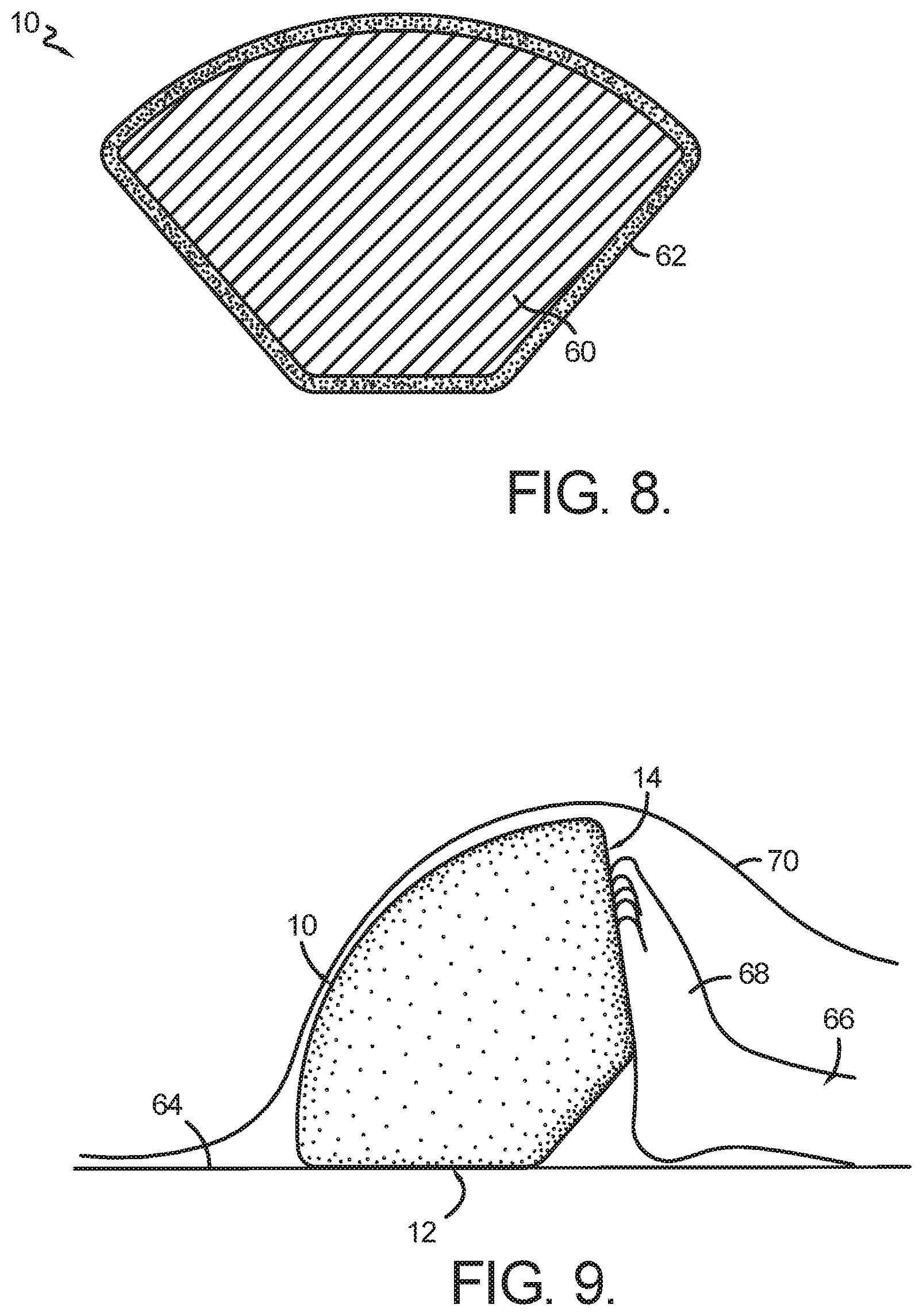
[0015] FIG. 8 is a cross-sectional view taken along line 8-8 in FIG. 2;
[0016] FIG. 9 is a side view of the comfort support apparatus shown in FIG. 1 showing one exemplary use;
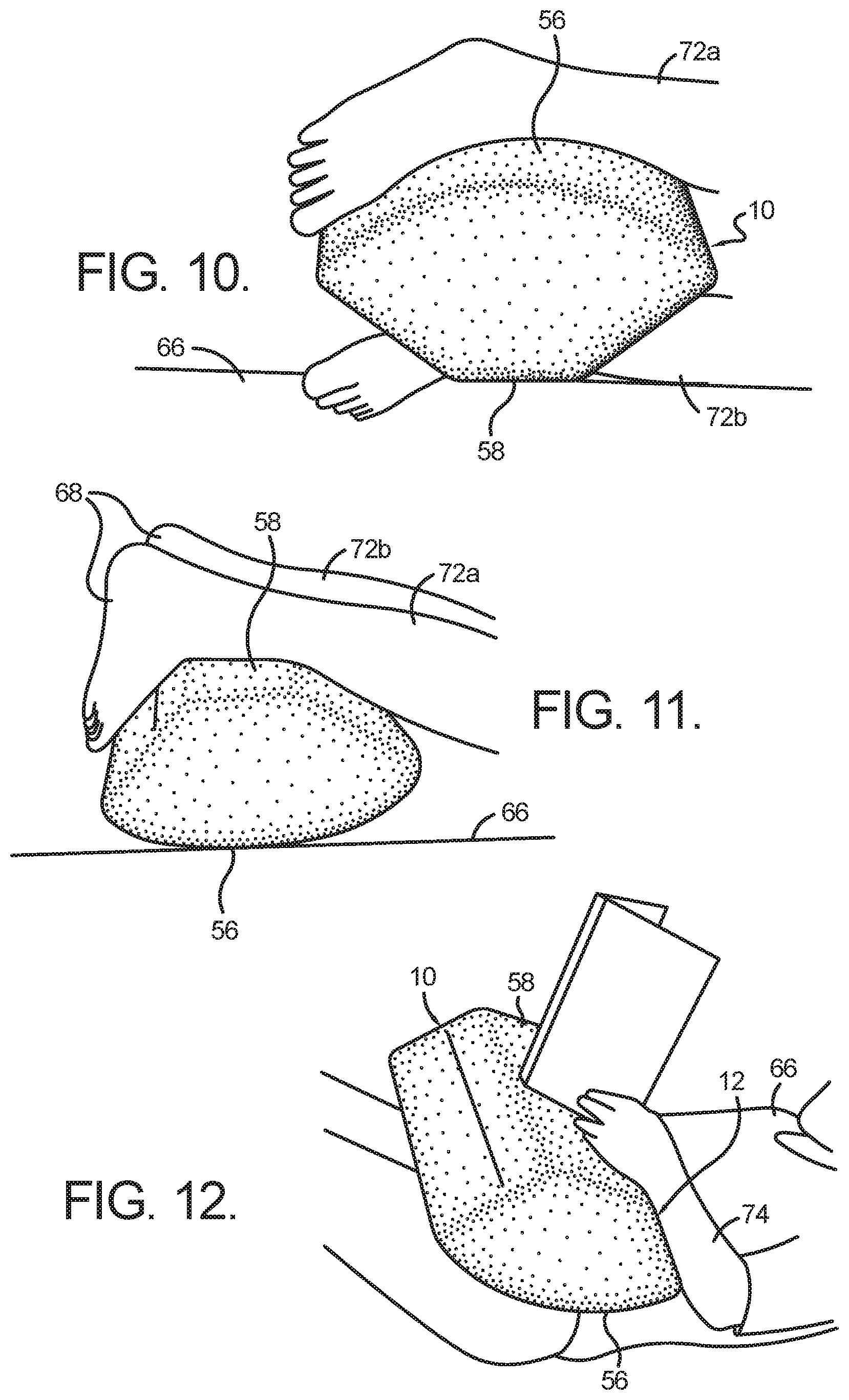
[0017] FIG. 10 is a side perspective view of the comfort support pillow shown in FIG. 1 showing another exemplary use;
[0018] FIG. 11 is a side perspective view of the comfort support pillow shown in FIG. 1 showing yet another exemplary use; and
[0019] FIG. 12 is a side front perspective view of the comfort support pillow shown in FIG. 1 showing a further exemplary use.
DETAILED DESCRIPTION OF THE INVENTION
[0020] Referring to the drawings in detail, and specifically to FIGS. 1-8, reference numeral 10 generally designates a comfort positioning device, such as a pillow, in accordance with an aspect of the present invention. In general, pillow 10 may be used in association with a human appendage, such as, but not limited to at least one foot, to assist with relief that may be needed when a user has a condition known as plantar fasciitis. For instance, pillow 10 may be used to promote stretching of the plantar fascia while the user sits or lies down, as will be described in more detail below. In other aspects, pillow 10 may also be used in association with at least one ankle, leg, arm or hand to provide support for these appendages in various contexts.
[0021] Pillow 10 includes first and second opposing side surfaces 12, 14. As best seen in FIG. 3, first side surface 12 may be flat and include a first end 16, a second end 18, a top end 20, and a bottom end 22. Top end 20 is convex-shaped when viewing the outside of pillow 10, and may be an arc including a radius having a length (L1+L2). Bottom end 22 is positioned between first and second side surfaces 16, 18, and top end 20 is positioned between first and second side surfaces 16, 18. As can be seen in FIG. 3, the length of top end 20 is greater than the length of bottom end 22. Further, first and second side surfaces 16, 18 are disposed at an angle 24 relative to one another. For example, angle 24 may be between approximately seventy degrees and approximately one-hundred degrees, and in another example angle 24 may be ninety degrees. Further, in an example where angle 24 is ninety degrees, bottom end 22 may be disposed at an angle 25 of one-hundred and thirty five degrees relative to first side surface 16, and be disposed at an angle 27 of one-hundred and thirty five degrees relative to second side surface 18. It should be understood that first and second side surfaces 16, 18 may have the same length (L1), and bottom end 22 extends from a bottom portion of first end side surface 16 to a bottom portion of second end side surface 18. For illustrative purposes only, and not to limit the scope of the invention in any way, the length (L1) of first end 16 may be 51/2 inches and length (L2) may be 25/8 inches.
[0022] As best seen in FIG. 6, second side surface 14 may be flat and include a first end 26, a second end 28, a top end 30, and a bottom end 32. Top end 30 is convex-shaped when viewing the outside of pillow 10, and may be an arc including a radius having a length (L3+L4). Bottom end 32 is positioned between first and second side surfaces 26, 28, and top end 30 is positioned between first and second side surfaces 26, 28. As can be seen in FIG. 3, the length of top end 30 is greater than the length of bottom end 32. Further, first and second side surfaces 26, 28 are disposed at an angle 34 relative to one another. For example, angle 34 may be between approximately seventy degrees and approximately one-hundred degrees, and in another example acute angle 34 may be ninety degrees. Further, in an example where angle 34 is ninety degrees, bottom end 32 may be disposed at an angle 35 of one-hundred and thirty five degrees relative to first side surface 26, and be disposed at an angle 37 of one-hundred and thirty five degrees relative to second side surface 28. It should be understood that first and second side surfaces 26, 28 may have the same length (L3), and bottom end 32 extends from a bottom portion of first end side surface 26 to a bottom portion of second end side surface 28. For illustrative purposes only, and not to limit the scope of the invention in any way, the length (L3) of first end 26 may be 51/2 inches and length (L4) may be 25/8 inches. Further, length (L3) may be equal to length (L1), and length (L4) may be equal to length (L2). Further, first and second side surfaces 12, 14 may have the same shape and/or proportions.
[0023] As best seen in FIGS. 1, 2, 3, 6 and 7, pillow 10 further includes a front surface 36. With specific reference to FIG. 2, front surface 36 may be flat and include a first end 38, a second end 40, a top end 42, and a bottom end 44. Front surface 36 extends between first and second side surfaces 12, 14. The first end 38 intersects with first end 16 of first side surface 12, and second end 40 intersects with second end 28 of second side surface 14. For illustrative purposes only, and not to limit the scope of the invention in any way, the length (L5) of front surface 36 may be 161/4 inches.
[0024] As best seen in FIGS. 1, 3, 4, 6 and 7, pillow 10 further includes a back surface 46. With specific reference to FIG. 3, back surface 46 may be flat and include a first end 48, a second end 50, a top end 52, and a bottom end 54. Back surface 46 extends between first and second side surfaces 12, 14. The first end 48 intersects with first end 26 of second side surface 14, and second end 50 intersects with second end 18 of first side surface 12. As best seen in FIGS. 3 and 6, back surface 46 lies on a plane that is disposed at angle 24 and/or 34 relative to the plane that front surface 36 lies on. For example, angle 24 and/or 34 may be between approximately seventy degrees and approximately one-hundred degrees, and in another example angle 24, 34 may be ninety degrees. For illustrative purposes only, and not to limit the scope of the invention in any way, the length (L6) of back surface 46 may be 161/4 inches.
[0025] As best seen in FIGS. 1-6, pillow 10 further includes a top surface 56. Top surface 56 extends between the respective top ends 20, 30 of first and second side surfaces 12, 14, and extends between the respective top ends 42, 52 of front and back surfaces 36, 36. As can be seen in FIGS. 1, 3 and 6, top surface 56 is convex-shaped, and may be an arc including a radius having a length (L1+L2 and/or L3+L4).
[0026] As best seen in FIGS. 1, 2, 3, 4, 6 and 7, pillow 10 further includes a bottom surface 58. Bottom surface 58 may be flat and extend between the respective bottom ends 22, 32 of first and second side surfaces 12, 14. Bottom surface 58 also extends between the respective bottom ends 44, 54 of front and back surfaces 36, 46.
[0027] As can be seen in FIG. 8, pillow 10 may include an inner core 60 and an outer casing 62. Inner core 60 may be formed of a polyurethane foam material to provide comfort to a user of pillow 10. Inner core 60 may be disposed within outer casing 62. Outer casing 62 may be formed of a stretch terry cloth and take the form of inner core 60 when used to enclose inner core 60.
[0028] Having described pillow 10 in detail, exemplary methods of using pillow 10 will now be provided. In one instance, a user may use pillow 10 to stretch his or her plantar fascia when in bed and under the bed covers. As best seen in FIG. 9, pillow 10 would be positioned on a support surface 64, such as a bed mattress, so that first side surface 12 is resting against support surface 64. A user 66 would then place the bottom of his foot 68 against second side surface 14 to place the foot in a position to keep the foot 68 in a flexed position to stretch the plantar fascia while resting in bed. Further, a bed cover 70 could then be draped over top surface 56 of pillow 10 to prevent bed cover from coming into contact with the toes of the foot 68 and thereby force the toes toward the bed mattress 64.
[0029] In another exemplary method, as best seen in FIG. 10, pillow 10 may be positioned between the feet, ankles and/or legs of user 66 to keep spacing between the user's legs to provide for a more comfortable position. In particular, one of the legs 72a of user 66 may be disposed on top of the convex top surface 56 of pillow, and the other leg 72b of user 66 may be disposed between support surface 64 and bottom surface 58 of pillow.
[0030] In yet another exemplary method, as best seen in FIG. 11, convex top surface 56 may be disposed against support surface 64, and bottom surface 58 of pillow 10 may provide support for the legs 72a, 72b of user 66 when user 66 is lying on his or her stomach. Pillow 10 allows for one or more feet 68 to remain in a normal position while user 66 is lying on his or her stomach and eliminates the need for the toes to be disposed in a pointed position against support surface 66.
[0031] In a further exemplary method, as best seen in FIG. 12, pillow 10 may be used in the lap of user 66 to provide support for a user's hands or arms. In particular, convex top surface 56 is disposed against the lap of user 66 and bottom surface 58 is used to provide the desired support. Further, the angled orientation of first side surface 12 provide a comfortable resting location for the arms 74 of user 66.
[0032] From the foregoing, it will be seen that this invention is one well adapted to attain all the ends and objects hereinabove set forth together with other advantages which are obvious and which are inherent to the device described herein. It will be understood that certain features and sub combinations are of utility and may be employed without reference to other features and sub combinations. This is contemplated by and is within the scope of the claims. Since many possible embodiments of the invention may be made without departing from the scope thereof, it is also to be understood that all matters herein set forth or shown in the accompanying drawings are to be interpreted as illustrative and not limiting.
[0033] The constructions described above and illustrated in the drawings are presented by way of example only and are not intended to limit the concepts and principles of the present invention. As used herein, the terms "having" and/or "including" and other terms of inclusion are terms indicative of inclusion rather than requirement. Further, it should be understood that the use of the terms "module" and "component" herein are interchangeable and shall have the same meaning.
[0034] While the invention has been described with reference to preferred embodiments, it will be understood by those skilled in the art that various changes may be made and equivalents may be substituted for elements thereof to adapt to particular situations without departing from the scope of the invention. Therefore, it is intended that the invention not be limited to the particular embodiments disclosed as the best mode contemplated for carrying out this invention, but that the invention will include all embodiments falling within the scope and spirit of the appended claims.
* * * * *
D00000
D00001
D00002
D00003
D00004
D00005
XML
uspto.report is an independent third-party trademark research tool that is not affiliated, endorsed, or sponsored by the United States Patent and Trademark Office (USPTO) or any other governmental organization. The information provided by uspto.report is based on publicly available data at the time of writing and is intended for informational purposes only.
While we strive to provide accurate and up-to-date information, we do not guarantee the accuracy, completeness, reliability, or suitability of the information displayed on this site. The use of this site is at your own risk. Any reliance you place on such information is therefore strictly at your own risk.
All official trademark data, including owner information, should be verified by visiting the official USPTO website at www.uspto.gov. This site is not intended to replace professional legal advice and should not be used as a substitute for consulting with a legal professional who is knowledgeable about trademark law.