Climate Controlled Headgear Apparatus
Feher; Steve
U.S. patent application number 16/486492 was filed with the patent office on 2020-07-23 for climate controlled headgear apparatus. The applicant listed for this patent is Steve Feher. Invention is credited to Steve Feher.
| Application Number | 20200229530 16/486492 |
| Document ID | / |
| Family ID | 63169621 |
| Filed Date | 2020-07-23 |


View All Diagrams
| United States Patent Application | 20200229530 |
| Kind Code | A1 |
| Feher; Steve | July 23, 2020 |
CLIMATE CONTROLLED HEADGEAR APPARATUS
Abstract
A headgear apparatus for delivering temperature conditioned air including passively or actively cooled, heated, or ventilated air to the interior of a shell is disclosed. A device housing which enshrouds a device for providing temperature conditioned air is placed on a rear portion of the shell. The device housing has air inlets and air rejector vents for delivering fresh air to and removing heated air from the device, and is configured to reduce the heated air from re-entering the device through the air inlets. The headgear apparatus is designed to withstand impact forces without injuring the wearer.
| Inventors: | Feher; Steve; (Beverly Hills, CA) | ||||||||||
| Applicant: |
|
||||||||||
|---|---|---|---|---|---|---|---|---|---|---|---|
| Family ID: | 63169621 | ||||||||||
| Appl. No.: | 16/486492 | ||||||||||
| Filed: | February 14, 2018 | ||||||||||
| PCT Filed: | February 14, 2018 | ||||||||||
| PCT NO: | PCT/US18/18260 | ||||||||||
| 371 Date: | August 15, 2019 |
Related U.S. Patent Documents
| Application Number | Filing Date | Patent Number | ||
|---|---|---|---|---|
| 62459563 | Feb 15, 2017 | |||
| Current U.S. Class: | 1/1 |
| Current CPC Class: | A42B 3/286 20130101; A42B 3/285 20130101 |
| International Class: | A42B 3/28 20060101 A42B003/28 |
Claims
1. A headgear apparatus, comprising: a shell including a first opening of such dimensions as to permit receipt onto the head of a wearer, the shell having a top portion shaped to fit over the upper scalp of the wearer, and a rear portion shaped to fit over at least a portion of the back of the head of the wearer; a device housing positioned on the rear portion of the shell, the device housing comprising a generally curved surface that emerges from an upper part of the device housing in contact with and emerging away from the shell extending downward toward the first opening of the shell, in which the device housing has two generally vertical side-walls nearly perpendicular from the curved surface, the device housing forming a cavity between the shell and an outer surface of the device housing in which an at least one air inlet is formed in the device housing, the device housing configured for detachment from the shell upon impact of the headgear apparatus; an air conducting layer distributed about substantially an entire interior of the shell; and, a device for producing a pressurized stream of air, the device receiving intake air from the at least one air inlet of the device housing and producing a pressurized stream of air in fluid communication with the air conducting layer.
2. The headgear apparatus of claim 1, in which the at least one air inlet is formed in both of the two generally vertical side-walls of the device housing.
3. The headgear apparatus of claim 1, in which the device and the device housing are configured to deform and absorb energy during an impact to the headgear apparatus.
4. The headgear apparatus of claim 1, in which the device housing is removably coupled to the shell.
5. The headgear apparatus of claim 1, in which the device is detachably coupled to the shell with a hook and loop fastener.
6. The headgear apparatus of claim 2, in which the device housing further comprises a rejector air outlet for exiting heated air, in which the rejector air outlet is positioned to prevent the exiting heated air from entering the at least one air inlet.
7. The headgear apparatus of claim 6, in which the rejector air outlet is formed in the generally curved surface of the device housing.
8. The headgear apparatus of claim 6, in which the device is a heat pump, in which the air moving past a hot place of the heat pump is exited to the rejector air outlet of the device housing.
9. The headgear apparatus of claim 8 is configured such that air moving past a cold place of the heat pump is caused to flow forward through the air conducting layer adjacent the scalp of the wearer.
10. The headgear apparatus of claim 1. in which the device is a Positive Coefficient Temperature type resistive heating element.
11. A headgear apparatus, comprising: a shell including a first opening of such dimensions as to permit receipt onto the head of a wearer, the shell having a top portion shaped to fit over the upper scalp of the wearer, and a rear portion shaped to fit over at least a portion of the back of the head of the wearer; a device housing positioned on the rear portion of the shell, an upper part of the device housing in contact with and emerging away from the shell extending downward toward the first opening of the shell, the device housing forming a cavity between the shell and an outer surface of the device housing, the device housing having at least one air inlet, the device housing configured for detachment from the shell upon impact of the headgear apparatus; an air conducting layer distributed about substantially an entire interior of the shell; and, a device for producing a pressurized stream of air, the device receiving intake air from the at least one air inlet of the device housing and producing a pressurized stream of air in fluid communication with the air conducting layer.
12. The headgear apparatus of claim 11, in which the device and the device housing are configured to deform and absorb energy during an impact to the headgear apparatus.
13. The headgear apparatus of claim 11, in which the device housing is removably coupled to the shell.
14. The headgear apparatus of claim 11, in which the device is detachably coupled to the shell with a hook and loop fastener.
15. The headgear apparatus of claim 11, in which the device housing further comprises a rejector air outlet for exiting heated air, in which the rejector air outlet is positioned to prevent the exiting heated air from entering the at least one air inlet.
16. The headgear apparatus of claim 15, in which the device is a heat pump, in which the air moving past a hot place of the heat pump is exited to the rejector air outlet of the device housing.
17. A headgear apparatus, comprising: a shell including a first opening of such dimensions as to permit receipt onto the head of a wearer, the shell having a top portion shaped to fit on the upper scalp of the wearer, and a rear portion shaped to fit on at least a portion of the back of the head of the wearer; a device housing positioned on the rear portion of the shell, the device housing in contact with and emerging away from the shell extending downward toward the first opening of the shell, the device housing forming a cavity between the shell and an outer surface of the device housing, the device housing having at least one air inlet, the device housing configured for detachment from the shell upon impact of the headgear apparatus; and, a device for cooling the scalp of the wearer, the device receiving air from the at least one air inlet.
18. The headgear apparatus of claim 17, in which the device and the device housing are configured to deform and absorb energy during an impact to the headgear apparatus.
19. The headgear apparatus of claim 17, in which the device housing further comprises a rejector air outlet for exiting heated air, in which the rejector air outlet is positioned to prevent the exiting heated air from entering the at least one air inlet.
20. The headgear apparatus of claim 19, in which the device is a heat pump, in which the air moving past a hot place of the heat pump is exited to the rejector air outlet of the device housing.
Description
RELATED APPLICATION INFORMATION
[0001] The present application claims priority under 35 U.S.C. Section 119(e) to U.S. Provisional Patent Application Ser. No. 62/459,563 filed Feb. 15, 2017 entitled "Air Conditioned Helmet, (ACH) & Convective Headgear," along with PCT App. No. PCT/US18/18260, filed Feb. 15, 2018, of the same title, the disclosure of both which are incorporated herein by reference in their entirety.
BACKGROUND
1. Field
[0002] The present application relates in general to headgear. More particularly, the present application is directed to air conditioned and convective helmets and other headgear.
2. Description of the Related Art
[0003] There are many situations, both work oriented and sport, in which the wearing of a helmet is necessary or highly desirable. Exemplary of but a few instances where wearing a helmet for a relatively long period of time is required are a motorcycle police officer; race car driver; and a military tank driver. Considerable discomfort can result from wearing a helmet, especially the full-face type, for even a short period of time particularly in warm or humid weather.
[0004] Accordingly, a need exists to provide a temperature controlled helmet and convective headgear.
SUMMARY
[0005] In one or more embodiments, the device is either a thermoelectric Peltier cooler or a resistive heater, preferably of the PTC type, designed into a housing with air movers, condensation control, and an air input adapter in the headgear. In one or more embodiments, the system housing may be exposed on the rear of the headgear, but the preferred embodiment is to fair it smoothly into the headgear and cover it with a cover that has two openings in it for ambient air to enter, and in the case of a thermoelectric system, for heated rejector air to exhaust out. In an embodiment, the device is preferably a Positive Coefficient Temperature ("PTC") type resistive heating element for warming, and a Peltier thermoelectric device for cooling.
[0006] In one or more embodiments, the device housing is preferably designed into the helmet shell and covered smoothly. The detachability of the device is only desired and necessary for certification of the system, including the device, when exposed on the outside of the headgear.
[0007] The preferred embodiment is an arrangement where the convector ventilating, cooling, or heating device/system/housing is enclosed with a cover that is smoothly integrated into the headgear outer surface to reduce or eliminate tangential impact induced rotational moment, and for good aerodynamics, where appropriate.
[0008] In an embodiment, the cooling system or heating system contains a device within its housing. The housing is either exposed on the rear of the headgear or is covered. The covers are removable for servicing and can be configured to be knocked off if desired, but that is not necessarily always necessary. If the system housing is exposed, then it can be configured to breakaway in tangential impact to reduce or eliminate rotating moments.
[0009] In one or more embodiments, when the device housing is exposed (i.e., not covered), the device housing is configured for detachment from the helmet upon impact on the helmet apparatus. The device hosing is configured for detachment from the helmet so that the air filter may be cleaned or replaced, or other servicing may be done, and then replaced. The device cover is designed to be firmly attached to the headgear, but is removable so that servicing or repairs may be accomplished and then be re-installed.
[0010] In a first aspect, a helmet apparatus is disclosed. The helmet apparatus comprises a helmet shell including a first opening of such dimensions as to permit receipt onto the head of a wearer, the helmet shell having a front portion shaped to protect the front face of the wearer, and a rear portion shaped to protect the back of the head of the wearer. The helmet apparatus further comprises a device housing positioned on the outer rear portion of the helmet shell, the device housing comprising a generally curved surface that emerges from the upper part of the device housing in contact with and emerging away helmet shell extending downward toward the first opening of the helmet shell, in which the device housing has two generally vertical side-walls nearly perpendicular from the curved surface, the device housing forming a cavity between the helmet shell and an outer surface of the device housing in which the at least one air inlet is formed in the device housing. The helmet apparatus further comprises an air conducting layer distributed about substantially the entire interior of the helmet shell, and a device for producing a pressurized stream of air, the device receiving intake air from the at least one air inlet of the device housing and producing a pressurized stream of air in fluid communication with the air conditioning layer.
[0011] In a first preferred embodiment, the at least one air inlet is formed in both of the two generally vertical side-walls of the device housing. The at least one air inlet is preferably formed in one of the two generally vertical side-walls of the device housing. The device and the device housing are preferably configured to deform and absorb energy during an impact to the rear of the helmet apparatus. The device housing is preferably removably coupled to the helmet shell. The device is preferably detachably coupled to the helmet with a hook and loop fastener. The device housing preferably further comprises a rejector air outlet for exiting heated air, in which the rejector air outlet is positioned to prevent the exiting heated air from entering the at least one air inlet. The rejector air outlet is preferably formed in the generally curved surface of the device housing. The device is preferably a heat pump, in which the air moving past the "hot" place of the heat pump is exited to the rejector air outlet of the device housing. The device is preferably a Positive Coefficient Temperature ("PTC") type resistive heating element.
[0012] In a second aspect, a helmet apparatus is disclosed. The helmet apparatus comprises a helmet shell including a first opening of such dimensions as to permit receipt onto the head of a wearer, the helmet shell having a front portion shaped to protect the front face of the wearer, and a rear portion shaped to protect the back of the head of the wearer. The helmet apparatus further comprises a device housing positioned on the outer rear portion of the helmet shell, the upper part of the device housing in contact with and emerging away helmet shell extending downward toward the first opening of the helmet shell, the device housing forming a cavity between the helmet shell and an outer surface of the device housing, the device housing having at least one air inlet. The helmet apparatus further comprises an air conducting layer distributed about substantially the entire interior of the helmet shell, and a device for producing a pressurized stream of air, the device receiving intake air from the at least one air inlet of the device housing and producing a pressurized stream of air in fluid communication with the air conditioning layer.
[0013] In a second preferred embodiment, the device and the device housing are preferably configured to deform and absorb energy during an impact to the rear of the helmet apparatus. The device housing is preferably removably coupled to the helmet shell. The device is preferably detachably coupled to the helmet with a hook and loop fastener. The device housing preferably further comprises a rejector air outlet for exiting heated air, in which the rejector air outlet is positioned to prevent the exiting heated air from entering the at least one air inlet. The device is preferably a heat pump, in which the air moving past the "hot" place of the heat pump is exited to the rejector air outlet of the device housing.
[0014] In a third aspect, a helmet apparatus is disclosed. The helmet apparatus comprises a helmet shell including a first opening of such dimensions as to permit receipt onto the head of a wearer, the helmet shell having a front portion shaped to protect the front face of the wearer, and a rear portion shaped to protect the back of the head of the wearer, and a device housing positioned on the outer rear portion of the helmet shell, the device housing in contact with and emerging away helmet shell extending downward toward the first opening of the helmet shell, the device housing forming a cavity between the helmet shell and an outer surface of the device housing, the device housing having at least one air inlet. The helmet apparatus further comprises a device for cooling the scalp of the wearer, the device receiving air from the at least one air inlet.
[0015] In a third preferred embodiment, device and the device housing are configured to deform and absorb energy during an impact to the rear of the helmet apparatus. The device housing preferably further comprises a rejector air outlet for exiting heated air, in which the rejector air outlet is positioned to prevent the exiting heated air from entering the at least one air inlet. The device is preferably a heat pump, in which the air moving past the "hot" place of the heat pump is exited to the rejector air outlet of the device housing. These and other features and advantages of the preferred embodiments will become more apparent with a description of preferred embodiments in reference to the associated drawings.
DESCRIPTION OF THE DRAWINGS
[0016] The above and other aspects, features and advantages of the preferred embodiments will be apparent from the following more particular description thereof, presented in conjunction with the following drawings and tables.
[0017] FIG. 1 is a rear view of an air conditioned helmet showing several components in an embodiment.
[0018] FIG. 1A is a rear view of helmet showing an alternative method of ducting air into the air flow structure liner.
[0019] FIG. 1B is a side view of an air conditioned helmet showing a Volara.RTM. insulator and lower air flow structure edge air seal replaced with the neck roll.
[0020] FIG. 10 shows the optional type 3 air filter behind air inlet openings and the rejecter air opening with or without grill.
[0021] FIG. 2 is a side view of an air conditioned helmet showing a removed cover in an embodiment.
[0022] FIG. 2A is a side view of helmet showing an alternative method of ducting air into the air flow structure liner.
[0023] FIG. 2B shows the main impact absorbing structure and the separate extended shell impact absorbing structure.
[0024] FIG. 2C is a side view of a helmet showing additional details of the components such as the optional air filter type 3, mounted behind vent openings in cover.
[0025] FIG. 3 is a plan view of a helmet showing the mounting of an air convection assembly without blowers.
[0026] FIG. 3A is a top view of a helmet having an extended shell that is smooth, without protrusions that could cause rotational neck injury from tangential impact.
[0027] FIG. 4 is a plan view of a helmet having two fans.
[0028] FIG. 4A is a side view of a helmet having an extended shell that is smooth and without protrusions.
[0029] FIG. 5 is a front elevation view of a helmet showing the air inlet for the thermoelectric pump.
[0030] FIG. 5A illustrate alternative air channels or slots, in foam, with an optional air permeable inner cushion layer 9
[0031] FIG. 6 illustrates a basic pattern for the convective helmet interior air flow structure.
[0032] FIG. 7 is a side elevation view of the thermoelectric air to air helmet thermoelectric heat pump.
[0033] FIG. 8 is a side elevation view air helmet convective system having after heater fins in an embodiment.
[0034] FIG. 8A is a side elevation view air helmet convective system having a two-stage Peltier cooler in an embodiment.
[0035] FIG. 8B is a side elevation view air helmet convective system having after heater fins in an embodiment.
[0036] FIG. 9 is a plan view of a helmet having tapered, aerodynamically smooth convective system fairings.
[0037] FIG. 10 shows a helmet with an extended shell.
[0038] FIG. 11 illustrates a side elevation view of the extended rear cover, or fairing, which is applied to the outside surface of a conventional helmet shell.
[0039] FIG. 12 is a heating apparatus in which a blower is coupled to the resistive heating element.
[0040] FIG. 12A is a heating apparatus in which a blower is coupled to the resistive heating element with widely spaced, overrated fins.
[0041] FIG. 13 is a plan phantom view of resistive heating elements.
[0042] FIG. 13A is an elevation view depicting the resistance heating elements with a low efficiency, low fin density heat exchanger.
[0043] FIG. 14 is an end elevation view of a heating module in an embodiment.
[0044] FIG. 14A is an end elevation view of a heating module in an embodiment, having optional baseplates.
[0045] FIG. 14B is an end elevation view of a heating module in an embodiment, having a conflux conductive heater in an embodiment.
[0046] FIG. 15 is a plan view of a heating module in an embodiment.
[0047] FIG. 15A is a plan view of a heating module having a lower density fin design in an embodiment.
[0048] FIG. 15B shows the conflux conductive elastomer or polymer PTC heater and a housing clamping folded fin heat exchangers.
[0049] FIG. 16 illustrates a helmet with air vent holes in rear surface of cover instead of on sides of cover.
[0050] FIG. 17 illustrates a covering for air duct for air entering the air flow structure on the edge of the structure instead of the rear surface of the air flow structure.
[0051] FIG. 18A is a top view of a removable lining in an embodiment.
[0052] FIG. 18B is a representation of the air flow within the helmet.
[0053] FIG. 18C is a perspective view of the air flow structure with an interior trim layer as fitted into a helmet.
[0054] FIG. 19A is a top view of a removable lining having an optional insulation layer in an embodiment
[0055] FIG. 19B is a representation of the air flow within the helmet.
[0056] FIG. 19C is a top view of a removable lining having an optional insulation layer in an embodiment.
[0057] FIG. 19D is a top view of a removable lining having an insulation layer or a partial insulation layer in an embodiment.
[0058] FIG. 20 illustrates a cooling and heating system in an embodiment.
[0059] FIG. 20A shows thermoelectric Pellets, flexible insulator/support planes, inner fins tapered outward, before bending and installing in housing, and outer fins tapered inward, before bending.
[0060] FIG. 20B shows a conventional non-flattened helmet shell rear surface and optional curved ceramic plates.
[0061] FIG. 21 illustrates a cooling and heating system in an embodiment.
[0062] FIG. 21A shows the conventional outside rear of helmet and assembly above after bending, fins are straight, originating from the same instant center.
[0063] FIG. 21B shows stamped copper or aluminum fins in a square U shape, straight, flat, rigid non-conductive fin.
[0064] FIG. 22 illustrates the location of the helmet air outlet vents that vent into the face area.
[0065] FIG. 22B shows double articulated TE modules with radii, designed for small air movers for maximum compactness and a low and high cooling mode.
[0066] FIG. 22C shows a side view of the helmet with a Tubular Spacer Fabric ("TSF") or other air flow layer, insulation or impact layer, an outer shell, a convective system, and a rear air inlet TSF lower edge air seal.
[0067] FIG. 22AB shows a plastic strip stitched to 3Mesh.RTM. or other air flow structure interior trim cover.
[0068] FIG. 23 is a perspective view of the trim molding.
[0069] FIG. 23A shows a thin flexible plastic strip stitched to finisher and trim, soft flexible air outlet vent grill finisher, and 3Mesh.RTM. or other air flow structure interior trim cover.
[0070] FIG. 23B shows a soft flexible air outlet vent grill finisher and 3Mesh.RTM. or other air flow structure interior trim cover.
[0071] FIG. 23C shows extruded or molded seal outer face.
[0072] FIG. 23D shows a closed plug, a side wall, where the plugs are shown spaced farther apart than normal for clarity.
[0073] FIG. 23E shows a front face, air outlets, a side wall, and a plug with opening for air outlet.
[0074] FIG. 23AB shows the helmet air flow layer interior trim/padding layer, an optional air tight layer to seal bottom edge of TSF or other air flow structure, and a plastic strip sewn to interior trim to anchor trim by inserting between EPS and shell.
[0075] FIGS. 24 and 25 are side views of a resilient mounting system in one or more embodiment
[0076] FIG. 26 is a plan and side elevation view of an empty grommet and a separate ball-pin.
[0077] FIG. 27 is a plan and side elevation view of a grommet coupled to a separate ball-pin.
[0078] FIGS. 28 and 30 are plan and side elevation views respectively of a helmet cover having a convective system cover extended from the shell.
[0079] FIGS. 29 and 31 are plan and side elevation views respectively of a helmet cover having a having a side air inlet and a rejecter air outlet for thermoelectric cooling system only.
[0080] FIG. 32 illustrates a means for attaching the air system to a helmet.
[0081] FIGS. 33 and 34 illustrate how the Velcro.RTM. strip or spot secures the thermoelectric heat pump assembly to the helmet shell resiliently.
[0082] FIG. 35 is a view of an air handling system.
[0083] FIG. 36 shows a TSF, or other air flow layer, where these optional radii depend on the size of the helmet.
[0084] FIG. 36A shows an expanded view of an example of the removable coupling/adaptor.
[0085] FIG. 37 shows an alternative convective system with smaller fins for a closer fit to a conventional headgear shell.
[0086] FIGS. 38 through 40AA, disclose an ACH thermoelectric assembly cover that is designed to integrate smoothly into the shape of the back of the helmet.
[0087] FIG. 38A is a top plan view image of the helmet with a smoothly integrated cover which eliminates increased rotational moment from tangential impacts.
[0088] FIG. 41 is a view of a helmet shell having a foam impact layer formed in a notch in lower back edge of helmet shell.
[0089] FIG. 42 is a cross-sectional view of the air/heating system coupling with the helmet shell through the notch or opening in lower back wall of helmet shell
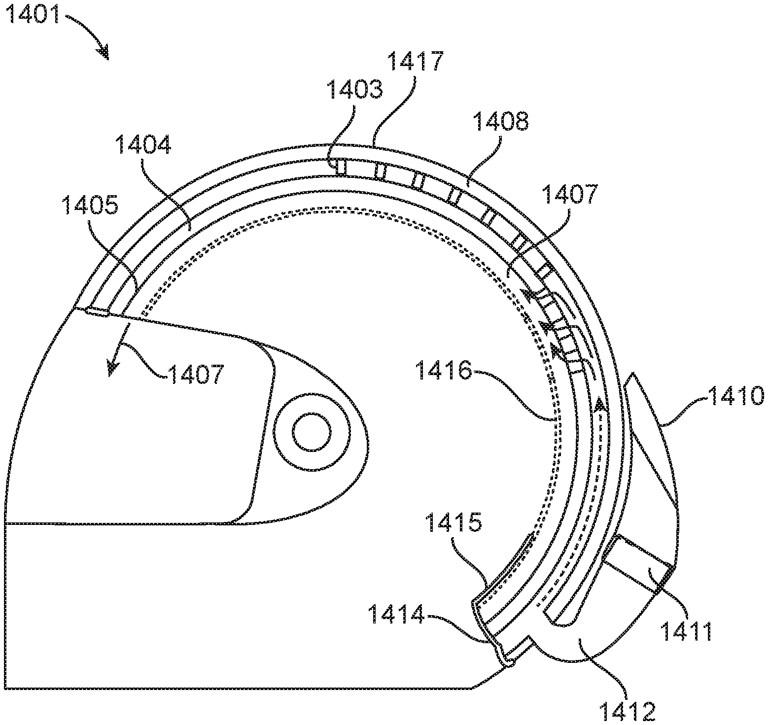
[0090] FIG. 42A is a cross-sectional view of the air/heating system coupling with the helmet shell through the notch or opening in lower back wall of helmet shell to the air duct to edge of air flow structure molded into foam layer overlapping air flow structure edge.
[0091] FIGS. 43 and 43A are side views of a cooling/heating system having an insert slot for coupling with a "radius insert."
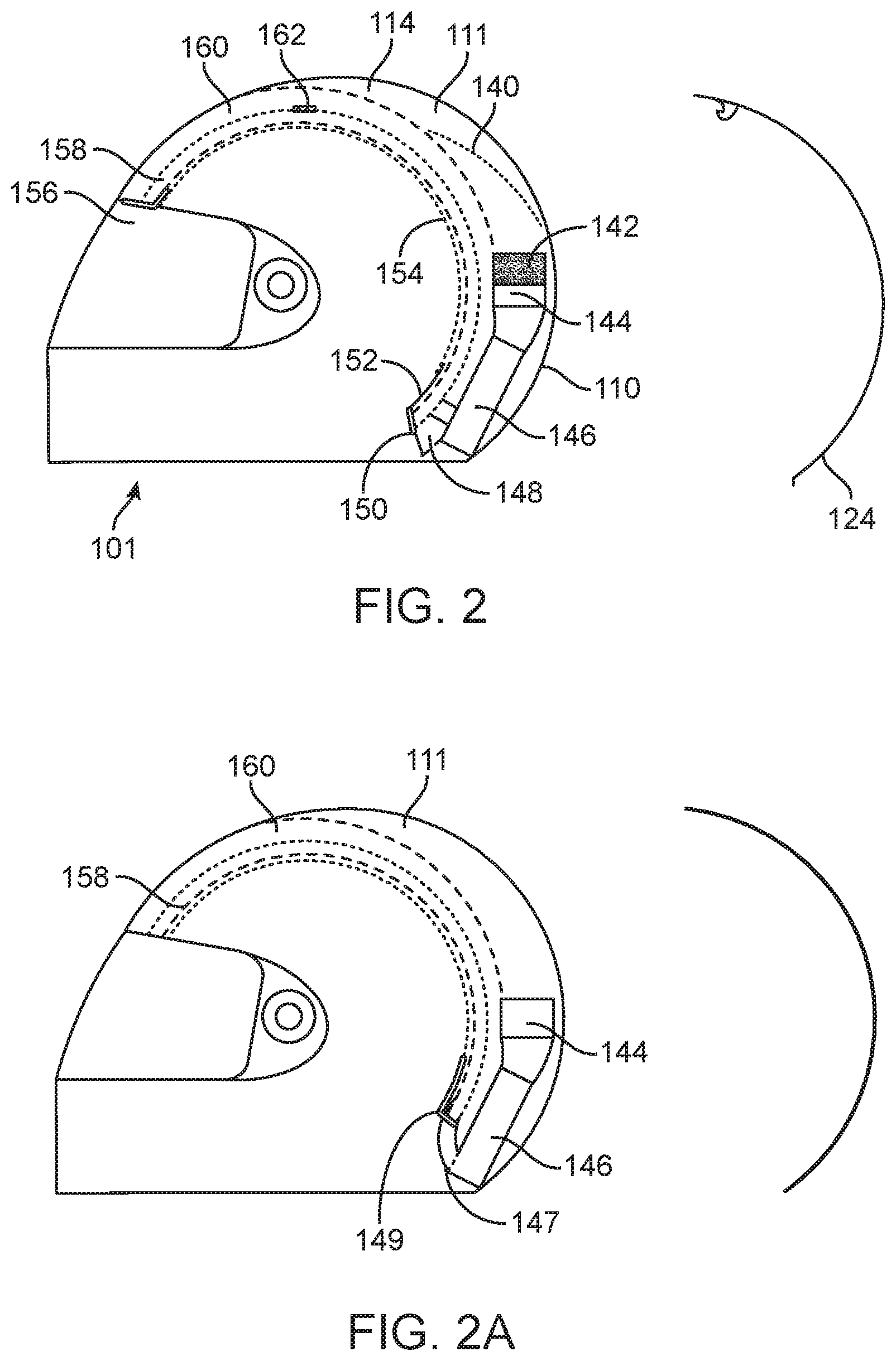
[0092] FIGS. 44 and 44A are side views of a cooling/heating system having an insert slot for coupling with a "radius insert."
[0093] FIG. 44B illustrates an air system having an isolation/decoupling material between air mover and adaptor, a fan/blower, an adaptor, a snap fit, a soft isolator, an air duct extension, and a second air mover isolator between air mover adaptor and convective housing.
[0094] FIG. 44C has a snap fit, a soft isolator, an optional EPS liner, and an air duct extension.
[0095] FIG. 44D shows an isolation/decoupling material between fan and adaptor, a fan/blower, an adaptor, a pliable convective system air duct with coupling/adaptor and vibration isolator, a shell, and an impact absorbing layer.
[0096] FIGS. 45-46 disclose a variation of the solutions disclosed in previous drawings of the subject disclosure involving the use of Velcro.RTM. as a semi-permanent fastener securing the convective assembly to the helmet shell while allowing the assembly to be readily separated from the helmet or cap in a direct tangential or lateral impact, or for repairs or replacement
[0097] FIG. 47 depicts a thermoelectric device with a fan housing in an embodiment.
[0098] FIG. 48 depicts a thermoelectric device with a fan housing in an embodiment, which includes an extended helmet air duct from the lower convective system housing.
[0099] FIG. 48A illustrates a preferred embodiment for coupling the TE device to the helmet.
[0100] FIG. 49 is a top view of the dual Durometer fan housing and adaptor.
[0101] FIG. 49A illustrates a preferred embodiment employing fan frames
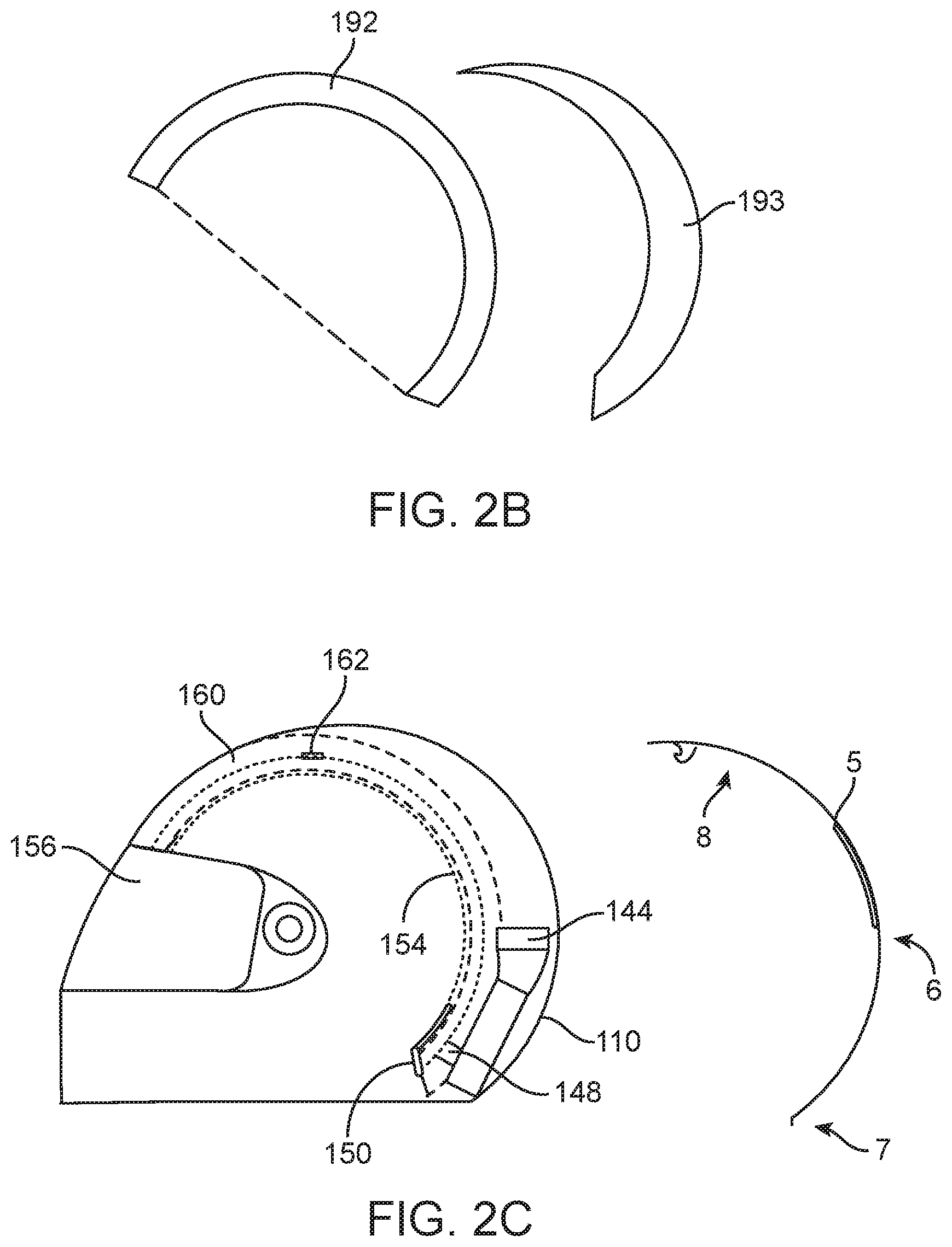
[0102] FIGS. 50-52 are a side elevation, a front or rear elevation, and a plan view respectively of an aerodynamically efficient housing for a bicycle ACH battery.
[0103] FIG. 53 is a perspective view of an ACH bicycle helmet in an embodiment.
[0104] FIG. 53A is a top view of a battery cord with connector to the helmet.
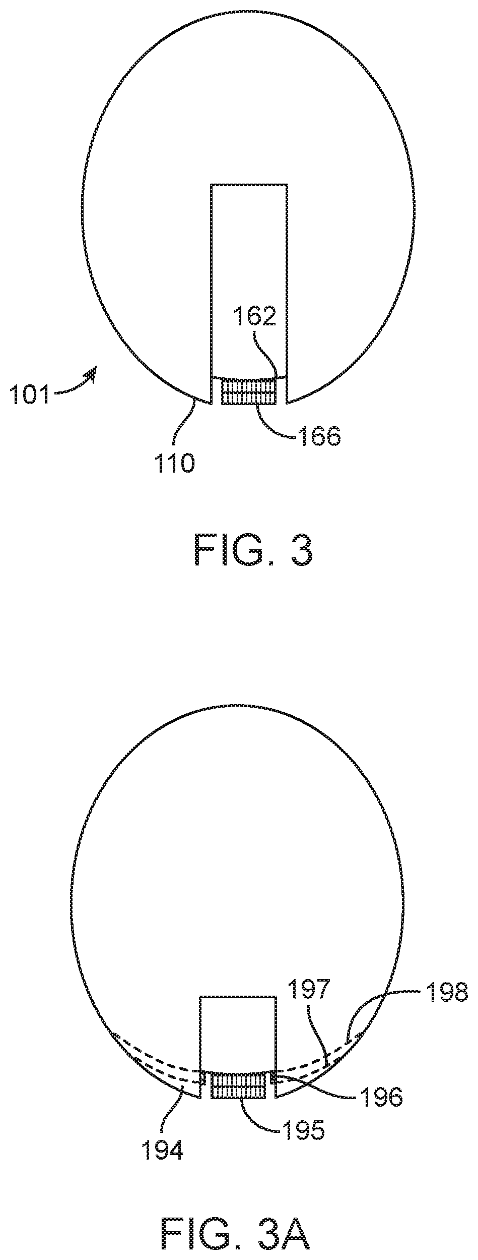
[0105] FIG. 53B is a side view of a bicycle helmet.
[0106] FIG. 54 discloses a unique wiring schematic for the ACH that includes switches that provide for off, ventilate, low cool and high cool, as well as providing accessories such as noise cancellation and Bluetooth.RTM. in one or more embodiments.
[0107] FIGS. 54A-54C discloses the circuit diagram for a system configured to be off, to ventilate, and to cool respectively.
[0108] FIG. 55 discloses a power cord with an optional dc-dc convertor in-line to enable the use of the helmet with different battery types and voltages.
[0109] FIGS. 56 through 58 disclose a variation of the novel method for controlling the cooling and heating power of a thermoelectric convective, or resistive convective system as used in embodiments, in the simplest, most cost effective way.
[0110] FIGS. 59-61 are front elevation, rear elevation, and side elevation view respectively housing holding a filter.
[0111] FIG. 61A is a perspective view of an air filter adaptor to fans housing holding an electrostatic air filter.
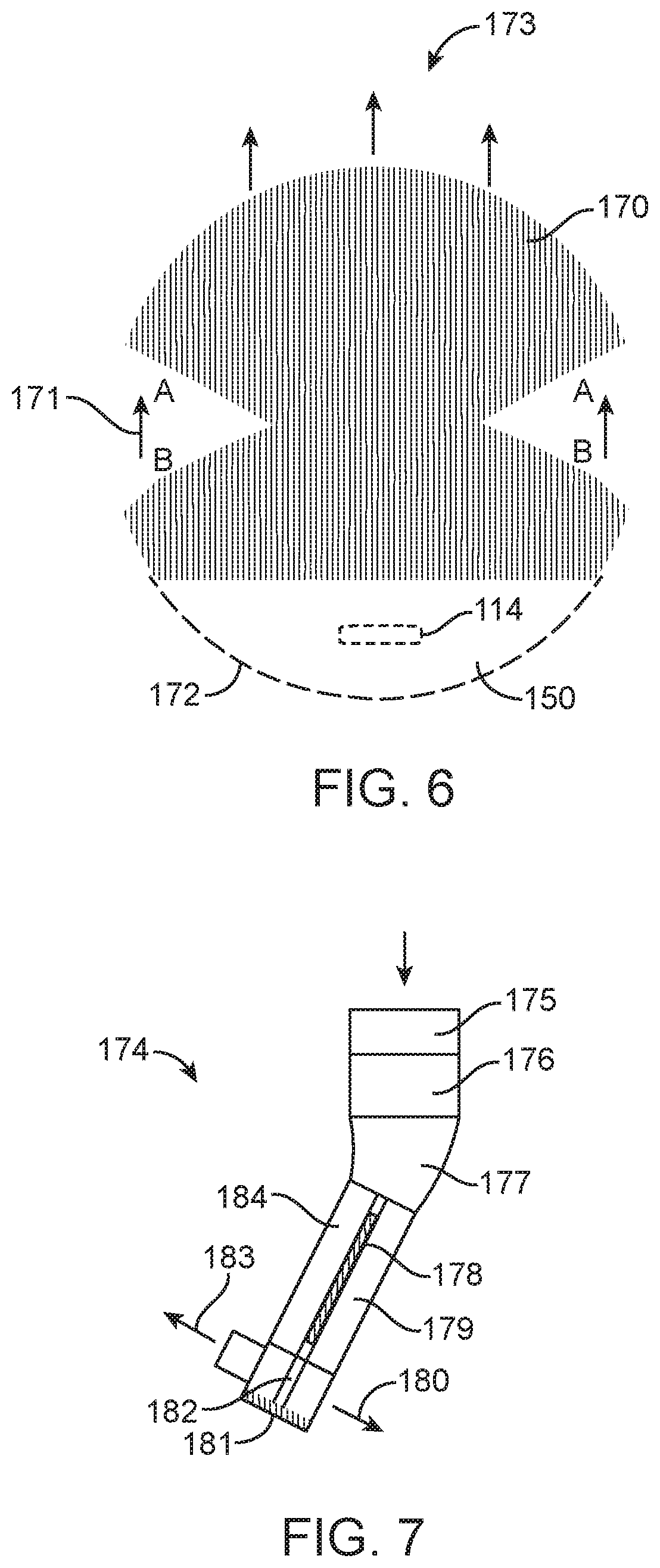
[0112] FIG. 62 is a cross-sectional view of a helmet having an extra, ultra-light weight configuration with several thin thermal insulation and a gusset at the rear to attach to the convective system.
[0113] FIGS. 63-65 depict equivalent electrical circuits for cooling or heating mode, ventilation mode, and heating or cooling mode respectively.
[0114] FIGS. 66-68 depict equivalent electrical circuits for being off, ventilating mode, and cooling mode respectively.
[0115] FIG. 69 shows an optional snorkel for blower or fan, to limit rain ingress and excessive air pressure in higher speed vehicle applications, a blower(s) or fan(s), a blower adaptor to helmet air inlet, preferably made of a medium Durometer urethane, an air inlet for air mover assembly, and a thermoelectric hot air outlet not necessary w/ ventilation only.
[0116] FIG. 70A illustrates a fan/blower(s), a fan/blower speed control potentiometer, a single pole, single throw switch, or switch can be incorporated into pot, and a power input.
[0117] FIG. 71 is a side view of a helmet showing an optional snorkel or filter adapter FIG. 72 shows an optional movable impact absorbing layer with variable densities or multiple movable layers, or elastic suspension elements to provide compliance between the user's head shell and the outer shell to reduce rotational trauma to the neck and/or brain.
[0118] FIG. 73 shows a rear view of a resistive air convection helmet and visor for snowmobiling for example, with optional extended shell and rear cover.
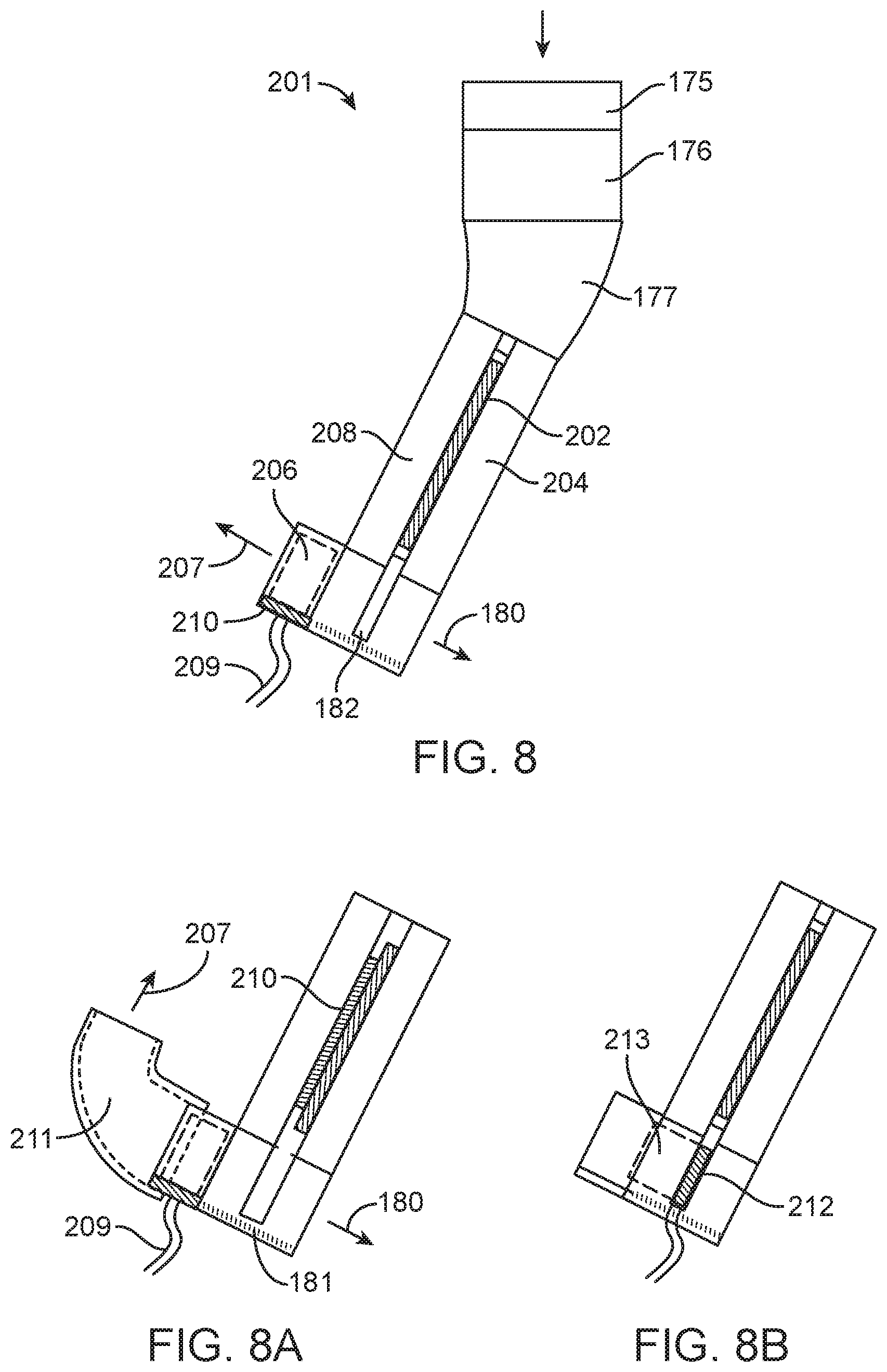
[0119] FIG. 73A is an electrical circuit of a fan/blower speed control including a potentiometer that controls the current flow to the fan/blowers.
[0120] FIG. 74 illustrates a soft air deflector above forehead to direct more warm air to the visor, and an optional thermal impedance layer to limit head warming with higher visor air temperatures.
[0121] FIG. 75A shows another ultra-light weight convective headgear design depicting an outer shell, an air flow structure layer, and an optional pad for optional Velcro.RTM. fastener for convective system.
[0122] FIGS. 75B-75F are perspective views of a bicycle air conditioned helmet ("BACH") in one or more embodiments.
[0123] FIGS. 75G and 75H are cross-sectional views of a bicycle air conditioned helmet ("BACH") in one or more embodiments.
[0124] FIGS. 76-79 shows a custom fit ACH employing a scanning method for determining an EPS mold pattern for TSF.
[0125] FIG. 80 illustrates an ACH, which contains a cooling system 1141, where a nominal load is .about.1.6 A @13.0 VDC.
[0126] FIGS. 80A-80C depicts equivalent electrical circuits without fan speed control in the off mode, ventilate mode, and cooling mode respectively.
[0127] FIGS. 80D-80F depicts equivalent electrical circuits with fan speed control in ventilate mode.
[0128] FIGS. 81 through 84 illustrate the basic application of audio speakers with optional Active Noise Cancellation, (ANC), to an air convectively cooled, heated, and/or ventilated helmet.
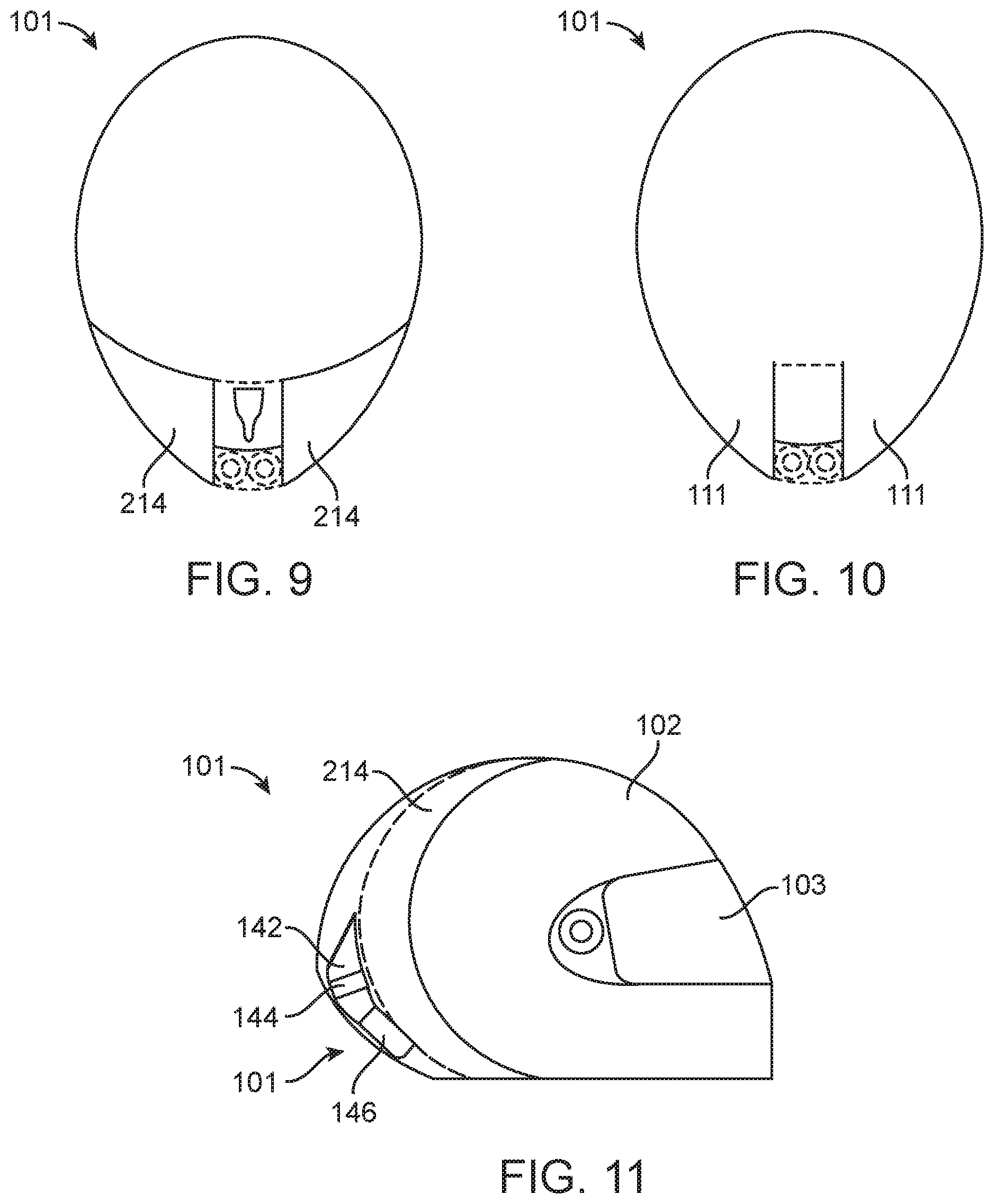
[0129] FIG. 85 is a side view of approximately 2-3 mm thick 3Mesh.RTM. or other TSF interior trim.
[0130] FIG. 86 illustrates a helmet shell, having a helmet impact absorbing foam, (EPS), or other impact absorbing structure.
[0131] FIG. 87 shows a channel for TSF or other air flow structure 1304 in EPS or other impact absorbing structure, a helmet shell 1305, an EPS, or other impact absorbing structure.
[0132] FIG. 88 is a side view of a helmet showing TSF or other air flow structure 1302 and insulation or impact layer 1306.
[0133] FIG. 89 is a side view of a helmet having optional elastic suspension elements to provide compliance between the user's head shell and the outer shell to reduce rotational trauma to the neck and/or brain.
[0134] FIG. 90 shows a side view of the helmet with a convective headgear internal air flow, an elastomeric bulb air pump to actuate retractable air dam, an air dam air release valve, an air flow through headgear venting through face area, and a retractable air dam at lower leading edge of full face type air convective helmet to promote good venting of headgear air from face area.
[0135] FIG. 91 illustrates an air flow through front air curtain vent.
[0136] FIG. 92 is a skin temperature chart that measures moderate ambient air temperature, which shows the thermoelectric convective headgear cooling function versus ambient temperature.
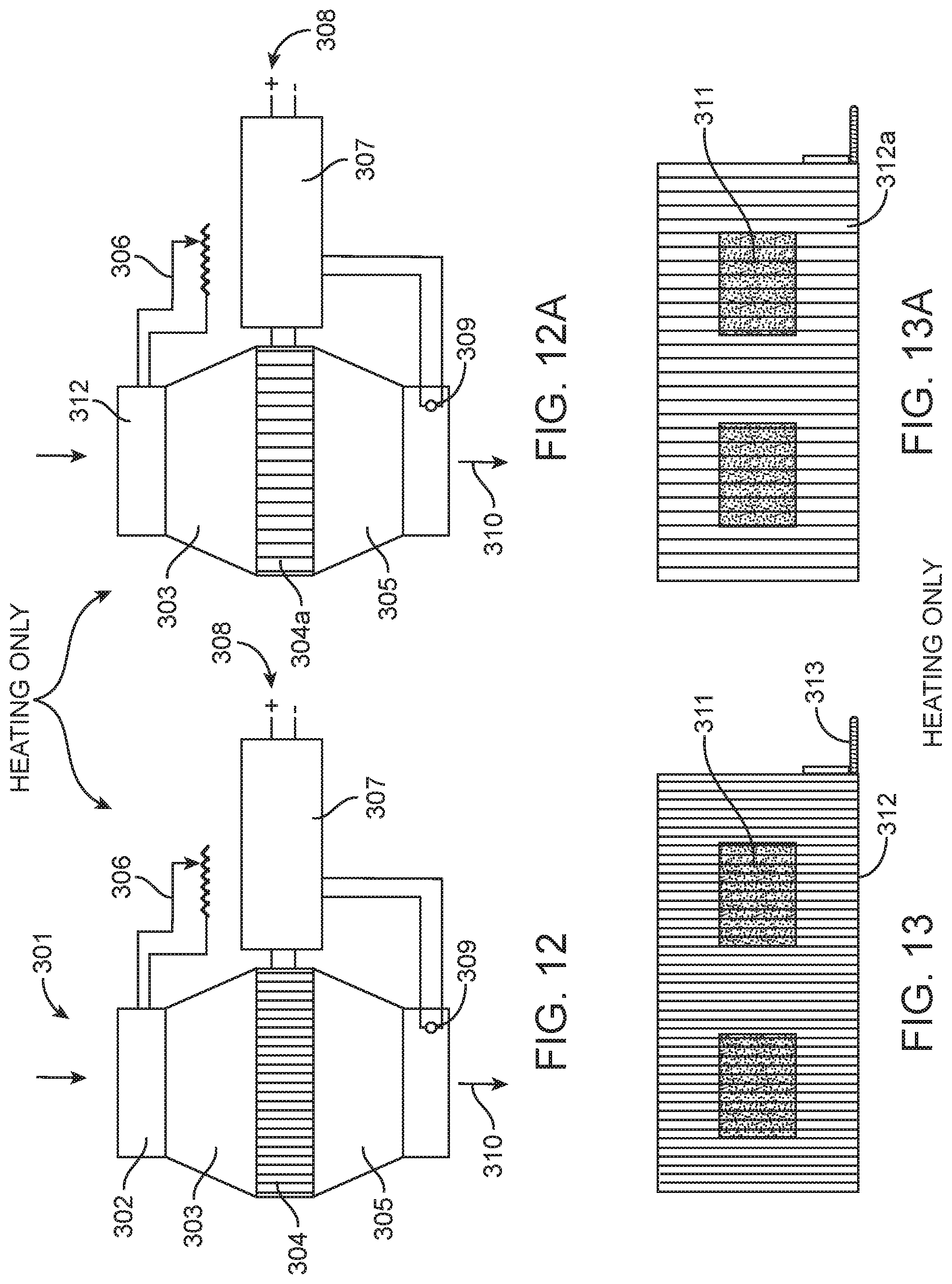
[0137] FIG. 93 is a chart of skin temperature as a function of ambient temperature which depicts the skin temperature on different parts of a nude person measure at different ambient temperatures.
DETAILED DESCRIPTION OF THE PREFERRED EMBODIMENTS
[0138] Teachings relating to the air conditioned helmets disclosed in U.S. patent application Ser. No. 11/252,089 filed Oct. 17, 2005 entitled "AIR CONDITIONED HELMET APPARATUS" which issued as U.S. Pat. No. 7,827,620 on Nov. 9, 2010, and U.S. patent application Ser. No. 10/601,964 filed Jun. 23, 2003 entitled "AIR CONDITIONED HELMET APPARATUS" which issued as U.S. Pat. No. 6,954,944 on Oct. 18, 2005, may be employed herein and the disclosures of which are incorporated herein by reference in their entirety.
[0139] As used herein and as is commonly known in the art, as depicted in FIGS. 1 and 1B, a helmet 101 has a helmet shell 110 having a first opening 30 of such dimensions as to permit receipt onto the head of a wearer. The helmet shell 110 has a front portion 31 shaped to protect the front face of the wearer, and a rear portion 32 shaped to protect the back of the head of the wearer. The helmet shell 110 has a top portion 33 covering the upper, scalp of the wearer, and a lower portion 36 near the base of the head of the wearer. A vertical axis 34, which is generally parallel with the neck and spin of the wearer, defines upper 33 and lower portions 36 of the helmet 101 and helmet 110. A horizontal axis 35 is generally perpendicular to the vertical axis 34. The term "heat pump" refers to a device which transfers thermal energy from a source to a destination which includes thermoelectric devices (e.g., Peltier devices). The brand name "Velcro.RTM." refers to hook and loop fasteners, usually comprising two components which are removably fastened when the two components are pressed together.
[0140] The following disclosure pertains to improvements in the thermoelectric air conditioned, or convective, helmet/headgear that was originally disclosed in U.S. Pat. No. 6,954,944 B2, and subsequently, in U.S. Pat. No. 7,827,620 B2. The improvements are in several areas:
[0141] 1--How to protect the thermoelectric apparatus from damage during the course of everyday use and even under moderate impact forces, while establishing a form that is aerodynamically and thermally efficient as well as aesthetically pleasing. The design must also ensure that the thermoelectric heat pump apparatus does not intrude into the interior of the helmet under severe impact forces, especially considering that the optimum design aerodynamically is not going to be knocked off readily in an impact because it is integrated into the shape of the helmet smoothly. A solution to packaging the cooling system into the helmet with the above considerations will be disclosed in this spec.
[0142] Another critical function of the new extended helmet shell design with indented or countersunk space for the thermoelectric air temperature modifying apparatus is to smooth the back of the helmet shell, eliminating any protrusions that could cause, as a result of a tangential impact, a rotation of the helmet, which would then cause a rotation of the user's neck, possibly causing neck injury. An additional solution has been added in the form of a standard helmet, with or without a slightly flattened rear surface, with a suitable cover over the convective cooling, heating, or ventilating system, to protect it in an impact and prevent any of the convective system from catching on something and inducing a rotation about the neck of the user in an impact. A number of variations of the convective system cover are also disclosed. The extended shell improvement is especially important because it enables the Air Conditioned Helmet ("ACH") to be certified by the appropriate approval agencies for use in transportation applications.
[0143] 2--During the air cooling process, especially in humid weather, moisture may be condensed out of the air that is blown into the helmet interior air flow structure. The resulting condensation will drip from it's source, the thermoelectric air to air heat pump built into the helmet, and may cause discomfort and/or a distraction for the user. A solution to this concern is disclosed in the following specification in the form of a condensation management system that evaporates condensation away as it's formed, in cooling mode.
[0144] 3--The concept and solution of using a resistive heating element to re-heat air sub-cooled below the dew point by a thermoelectric air to air heat pump, including a two stage Peltier device, in order to adjust the relative humidity of the air delivered to a cushion that is sat on or laid on was introduced in patent, U.S. Pat. No. 7,272,936 B2. This disclosure will show how that concept can be applied to a thermoelectric air conditioned helmet, in a compact, lightweight form.
[0145] 4--An air convection heated helmet for use in freezing and sub-freezing temperatures to prevent helmet visor fogging and icing and to provide comfortable air for breathing, which will also significantly reduce body core heat loss in cold weather by providing air at a higher and much more comfortable temperature, i.e. .about.60.degree. F. vs. 20.degree. F. or colder.
[0146] 5--A high efficiency ventilated helmet/cap/hat for head cooling in ambient weather conditions in which ambient air temperature is sufficiently low enough to accomplish a meaningful degree of body cooling via the head and scalp without the need for sub-ambient cooling. This new ventilated version is particularly suited for bicycling and running applications in moderate to cool weather as it reduces cost and weight of both the headgear and the battery required to run it.
[0147] 6--High efficiency air convection cooled, heated, or ventilated helmets for industrial applications such as welding and grinding, including specialized equipment known as a Powered Air Purified Respirator, or PAPR, for welding and grinding materials that involve toxic fumes.
[0148] 7--Numerous additional improvements, including manufacturability, improved air filtration, certification, safety, repair, and maintenance considerations.
[0149] FIG. 1 is a rear view of an air conditioned helmet ("ACH") 101 showing several components in an embodiment. The helmet 101 comprises an extended rear of helmet shell 110 having a space/channel 112 formed by extended rear sides of shell to form an air inlet 114. The helmet 101 has an air inlet 118 through shell 110 into helmet impact absorbing layer. Slots or grooves 116 for flanges on cover and a platformed edge with slots 122 for clips on cover to countersink cover flush with shell outer surface are formed in the helmet 101. An optional boss with Rivnut 120 to secure top of TE cover with screws may be formed in the helmet 101
[0150] A multiple blower type TE heat pump 130 and a single blower type TE heat pump 132 are shown. The rear cover 124 may have an optional NACA inlet duct 134 if cover completely covers channel. Other openings can also be used. The rear cover 124 has a rejecter air opening 136 with or without the grill. The rear cover 124 has a rejector heat exchanger, (hot side in cooling mode), air outlet, removably or permanently attached. This is shown with a hooked extension type top fastener.
[0151] FIG. 2 is a side view of an air conditioned helmet showing a removed cover in an embodiment. The helmet 101 has a shell extension 111. Air enters the air inlet 114 and passes through optional air filters type 1 140 and air filter type 2 142 to a fan or blower 144. The helmet 101 has a convective system 146 countersunk into rear space/channel of shell extension, and an air duct 148 from heat pump to helmet air flow structure/liner. It passes through aperture in helmet shell and impact absorbing layer 160. This is where the optional new relative humidity control resistive heater is optimally located. The helmet 101 has a lower rear air flow layer edge seal 150, an air and thermal barrier layer 152, preferably Voltek Volara.RTM., .about.1-2 mm thick, and knitted spacer fabric 154, such as 3Mesh.RTM., and an air flow structure cover trim. The helmet 101 has an optional Tubular Spacer Fabric ("TSF") TSF Air Vent Trim Grille Material 156, a TSF air flow liner 158, and optional impact absorbing layer 160, as well as a countersink 162 for TSF or other air flow structure fastener, Velcro.RTM. disc, for example.
[0152] FIGS. 1 and 2 show views of the new air conditioned helmet 101 design with an extended rear section 110 that creates an indented area that countersinks a thermoelectric air to air heat pump, or resistive heating system, or ambient ventilating system, inside the countersunk area in order to integrate the heat pump into a helmet 101 with a smooth outer shell. A rear cover 124 is shown which covers the heat pump assembly for good appearance, protection of the convective apparatus, and smooth aerodynamics. Also shown are two configurations of convective apparatus, one with a single blower 132, and the other with two or more blowers 130. The multi blower 130 configuration enables a less exaggerated rear extension of the helmet shell because the diameter of the dual fans/blowers is considerably smaller. It is possible to reduce the rear extension 110 further by using a larger number of smaller fans or blowers, and segmented Peltier devices, or resistive heaters, or a simple adaptor for ventilation only.
[0153] FIG. 1 also shows an optional NACA ambient air inlet duct 134 in an air convection assembly cover that is closed except for the NACA inlet 134 and a thermoelectric secondary, or hot air rejector outlet, for sub-ambient cooling.
[0154] FIG. 2 shows a view of the optional air flow structure air outlet vent trim 156 as disclosed earlier elsewhere in this disclosure, from a different view in order to show that it is possible for the grille trim 156 to be fastened to the optional helmet impact absorbing layer 160 with the air flow structure inserted behind it, instead of bonding the grille to the TSF. Very importantly, it is also possible to fold the interior air flow structure cover trim material 156 over the edge of the TSF, or other air flow structure, air outlet to conceal the air outlet edge of the air flow structure, however the ACH air flow structure interior surface trim cover is best accomplished with Muller Textil 3Mesh.RTM. knitted spacer fabric, or an identical equivalent. An example of a Muller 3Mesh.RTM. material that is very good from a thermal standpoint and a cushioning standpoint in a relatively thin sheet, (3 mm), is Muller 3Mesh.RTM. 5683-0300-2300-0015, which is also suitable for wrapping around the air outlet edge of the air flow structure because of an extremely low transverse pressure drop through the material. Another version of the same type of knitted spacer fabric is made by Macro International in a 2 mm thickness, which also produces an excellent result with good thermal transfer to and from the air in the TSF layer, while providing a good level of cushioning to help compensate for small variations in head shapes for any given size of helmet. Knitted spacer fabric, such as the Muller Textil material disclosed above, performs better than open cell foam in terms of thermal transfer, air, and vapor permeability, as well as cushioning performance than open cell foam. This is because the fibers that cross from one side to the other side of the plane of the 3Mesh.RTM. type material bend like leaf springs when the material is compressed. The bending of the fibers is highly directional so that the permeability of the material is not affected by compression nearly as much as open cell foam. Closed cell foam is, of course, a good insulator, so it is not appropriate as an ACH air flow structure interior trim finisher, unless it is used specifically to insulate a particular part of the helmet interior, and in that case, Voltek Volara.RTM. is an excellent material, being a radiation cross-linked closed cell foam with very small cells, enabling a very thin sheet, approximately. 1-2 mm thick, with small closed cells and high insulation, (R), values. FIG. 2 discloses the use of Volara.RTM. as an insulation layer 152 for the air flow structure air inlet area opposite the air inlet 114 into the air flow structure to prevent cold spots on the user's head/neck with cooling or hot spots with heating, and to seal the bottom rear edge of the TSF, or other air flow structure. FIG. 1 illustrates two solutions to the attachment of the cooling system cover to the helmet shell. One method is a slot in the shell that receives a flat flange with a hook on it. Pushing the cover 124 from top towards the bottom will cause the cover 124 to bend slightly, releasing the hooked extension from the slot and allowing the cover 124 to swing out, where it can then be pulled up so that the flange(s) on the bottom edge will pull out of corresponding slots or grooves 116 in the bottom edge of the indentation in the shell.
[0155] The other approach is to add a small boss 120 to the lower inside edge of the countersunk channel as shown to provide a space for a Rivnut, which is a female fitting that is installed like a Pop Rivet, with threads on the inside diameter. A screw can then be used to secure the cooling system cover in place at the top, with the lower flange and groove, or flange and slot, retaining the cover at the bottom. The cover is molded into the same shape as the corresponding surface at the rear of the helmet so that any impact to the cover will transmit to the helmet shell via the attachment points and the platformed edge of the indented channel that the cover matches up to. FIG. 2 includes a view of the TE cover with a hooked extension at the top instead of an opening for a screw fastener, and optionally, a short extended edge at the bottom engages into the slots or grooves at the bottom of the shell rear as shown in FIG. 1.
[0156] FIG. 2 illustrates an optional air filter type 1, which is an air filter positioned in the air channel formed by the extended shell type ACH. The position is as shown in order to provide the maximum amount of filter cross-section area for minimum air pressure drop into the fans, which are very small and therefore more susceptible to excessive inlet suction head pressure drop.
[0157] FIGS. 1A and 2A illustrate an alternative method of ducting conditioned air into the ACH air flow structure liner underneath the helmet lower back edge. FIG. 1A is a rear view of the helmet showing an alternative method of ducting air into the air flow structure liner. A notch 126 in the shell is preferred for the edge input to the air flow structure, as shown in FIG. 1A because it allows the helmet to rest normally on a flat surface when not being used. Without a notch, the air duct projects below the shell edge and causes the helmet to wobble in an unstable manner on a flat surface, and the weight of the helmet puts stress on the air duct itself.
[0158] FIG. 1B is a side view of an air conditioned helmet showing a Volara.RTM. insulator and lower air flow structure edge air seal of FIG. 2, replaced with the neck roll 191, (pad), and/or interior trim, to seal the TSF lower edge and also prevent a cold spot, which is a preferred embodiment. This is also shown in FIG. 48. FIG. 1B also depicts an optional snap fastener 190 for neck roll, pad, or interior trim to cover lower rear surface and bottom edge of air flow structure.
[0159] FIG. 1B is very similar to FIG. 2, however FIG. 1B discloses an important new additional optional solution to the problem of sealing the lower edge of the air flow layer and simultaneously insulating to prevent a cold spot on the back of the user's head and/or neck opposite the air input in the cooling type ACH with air entering at approximately 90 degrees to the direction of flow from the back to the front of the helmet, as opposed to the type of ACH where the air flow is directed into the air flow structure/layer along the edge of the TSF at approximately 0.0 degrees to the direction of air flow through the TSF, as disclosed in FIG. 2A. The preferred solution is to use an air tight neck roll, pad, or interior trim piece, configured as shown in FIG. 1B, and FIG. 48, to both seal the bottom edge of the TSF, or other air flow structure, to prevent air leakage, and cover and partially insulate the lower .about.1-3'' of forward facing inside surface of the TSF or other air flow structure to reduce thermal transfer and prevent a cold spot on the user's neck and/or lower head in cooling mode, or a warm/hot spot in heating mode, and prevent the leakage of cooled, heated, or ventilating ambient air entering the air flow structure from leaking out on the lower rear edge of, or region near, the air inlet of the air flow structure. This is a preferred embodiment, as it eliminates the Volara.RTM. insulation layer and adhesive, and a separate bottom edge seal with adhesive for a cleaner, simpler, and more efficient assembly process.
[0160] FIG. 10 shows the optional type 3 air filter 2 behind air inlet openings and the rejector air opening 3, with or without grill. FIGS. 10 and 2C, illustrate a full face motorcycle type ACH/AVH with the air inlet vent and filter installed in the cover for the convective apparatus. In this design, the cover covers the entire space that contains the convective cooling, heating, or ventilating apparatus, and has an air inlet with filter, preferably of the electrostatic mesh type, mounted on the inside behind the air inlet vent openings on the cover, called optional air filter type 3, and an opening to accommodate the auxiliary air outlet for a thermoelectric heat pump, if necessary. FIG. 10 is a variation of FIGS. 1 and 2, which discloses air filters type 1 and 2.
[0161] FIG. 2A has a convective system 146 mounted in space at rear surface of helmet formed by the extended shell, an air duct 147 from the heat pump to helmet air flow structure liner, wraps around rear helmet shell and impact layer bottom edge, and an air flow layer bottom edge seal except where air enters the layer on the edge 149.
[0162] FIG. 2B shows the main impact absorbing structure 192 and the separate extended shell impact absorbing structure 193. FIG. 2B discloses another solution to the extension of a helmet shell to accommodate an air convective cooling and heating, heating, or ventilating system. In this solution, the extended parts of the outer shell are fitted with separate molded impact absorbing elements, instead of a single piece impact layer, made of a suitable material, such as expanded polystyrene foam, (EPS), for example. The purpose of the separate extended elements is to make it easier, if necessary, to insert the extended impact absorbing structure into the extended outer shell. The ease with which a one piece impact absorbing structure can be inserted into an extended outer shell will be determined to some extent by the overall shape and design of the extended outer shell, and in some instances, the multi-piece impact absorbing structure will facilitate the assembly of an ACH with extended shell and impact absorbing layer(s).
[0163] FIG. 2C is a side view of a helmet having an optional air filter 4 type 3, mounted behind vent openings in cover, and a rear cover with rejector heat exchanger, 5 (hot side in cooling mode), air outlet, which is removably or permanently attached. Here it is shown with hooked extension type top fastener. The cover is removed by pushing down at top to disengage the hook fastener. 6. The cover 6 has a hook or flange on lower edge 7 to retain bottom of cover. This rear cover 8 covers the entire space containing the TE, ventilator, or heating system.
[0164] FIG. 3 illustrates a helmet 101 showing an approximate standard helmet rear surface 162, the shell surface at the rear of the helmet 110 extended beyond the standard surface 164, and convective assembly 166 shown without fan or blower(s), protected by indentation into helmet shell, or extended shell, depending on how you look at it. Shell is smooth, without protrusion that could cause rotational neck injury from tangential impact. Rear cover is not shown for clarity. FIG. 4 illustrates a helmet 101 having an air inlet 114 and a TE assembly shown with multiple blower configuration 130 where the rear cover is not shown for clarity. FIG. 4 is an elevation view of the helmet 101 showing the convective system air Inlet 114 shown with rear cover installed, forming the top surface of the air inlet 114. FIG. 5A illustrates alternative air channels or slots 10, in foam 11, with an optional air permeable inner cushion layer 9. This may not be the preferred embodiment.
[0165] FIGS. 3A and 4A are a top view and a side view of a helmet having an extended shell that is smooth, without protrusions that could cause rotational neck injury from tangential impact. The helmet has an extended shell surface 194 at the rear of helmet, a TE heat pump, ventilation system, or heating system assembly 195 shown without air mover(s), protected extended shell, where the shell is smooth, without protrusions that could cause rotational neck injury from tangential impact. The helmet also has an air filter 196, and air duct 197, and one or more air inlets 198 in EPS or other structure.
[0166] Specifically, FIGS. 3, 4, and 5 show two plan views and one front elevation view of the new ACH. FIG. 3 shows the mounting of an air convection assembly 166 without blowers and how it is countersunk into the extended rear section of the helmet. FIG. 4 shows the same with a two fan setup 130. FIG. 5 shows the air inlet 114 for the thermoelectric heat pump, defined by the countersunk area for the heat pump that tapers up toward the top front of the helmet and the rear cover that constitutes the outer wall of the air channel from the top front of the helmet to the rear of the helmet in which the convective cooling, heating, or ventilating system is located with helmet air entering the back of the helmet in order to duct air into the helmet interior air flow structure, which can be any structure capable of conveying air past the users' head, including, for example, grooves or channels in the impact absorbing EPS, (Expanded Polystyrene), or another impact absorbing system or layer, as depicted in FIG. 5A but is preferably made of Tubular Spacer Fabric, TSF, without the need for air channels and their associated pressure drop and reduced exposure of the user's head to temperature modified air, and disadvantages as described elsewhere in this disclosure. Impact certification is necessary for motor vehicle helmets and a secondary impact from channels collapsing after an initial impact force spike in the EPS would almost assuredly prevent certification due to additional potential trauma from a secondary impact force spike.
[0167] To summarize, the advantages of the extended shell design are:
[0168] 1--Eliminates air convection system external projections that could catch on objects during a crash and induce a rotation of the helmet about the neck in an impact.
[0169] 2--Eliminates external air switches and air scoops, and multiple openings, in the helmet shell that reduce the overall strength of the helmet shell. The extended shell ACH is stronger, and potentially lighter, as a result. In addition to a strength increase, the noise of the helmet will be reduced because of reduced air turbulence due to the reduction or elimination of projections from the surface of the shell.
[0170] 3--Because the shell is extended rear-wards, it is possible to introduce more aerodynamic stability by placing the aerodynamic center of pressure behind the center of gravity, which produces a self-stabilizing effect, whereas placing the aerodynamic center of pressure in front, or nearer the front of the center of gravity will tend to induce oscillations and reduce aerodynamic stability.
[0171] FIG. 6 illustrates a basic pattern for the convective helmet interior air flow structure, showing the air inlet 114 (air in duct profile example shown as a dashed line for clarity), the lower rear edge air seal 172 if neck roll is not used instead, and an insulation layer 150, preferably Voltek Volara.RTM., 0.031''-0.062'' thick and 2-4 lb./ft.sup.3 to prevent cold spot formation where air enters the helmet. Dotted line shows the approximate air entrance duct on opposite side of insulation. This may be preferably replaced with a modified neck roll, or pad, to cover and insulate same area, as shown in FIG. 1B and FIG. 42. FIG. 6 also shows the airflow 171 when fitted into the helmet interior through the TSF or other air flow layer cutting pattern 170 cut with a computer controlled laser. The basic approximate pattern for ACH TSF air flow liner with maximum internal area coverage in one piece before folding and inserting into a helmet. Note orientation of tubes for proper air flow when folded and formed into the interior of the helmet. This may also be used in a cap or hat for running, jogging, medical purposes, etc., when inserted into a suitable shell, which may be rigid or flexible. Different types and shapes of helmets may entail variations in this basic pattern for optimal fit and air flow. When formed into the interior of a helmet, the pattern shown lines up edges A with edges B, facilitating a smooth interior surface and continuous air flow from the entrance at the rear across the top and also along the full length of the sides for complete air flow coverage of the user's head. FIG. 6 shows the air out front 173, into face area in full face type ACH 101.
[0172] FIG. 6 shows the basic pattern for the convective helmet interior air flow structure, whether Tubular Spacer Fabric, (TSF), or another air flow lining 170 that is fitted inside a helmet 101 or a suitable shell for other applications, such as a bicycle helmet, runner's cap, etc.
[0173] The pattern shown in FIG. 6 guides some of the air convection system air from the inlet behind the user's head up, over, and around the head and vents down into the space in front of the user's face. Note the two somewhat triangular sectors removed so that the material edges fit together smoothly when the whole piece is inserted into the helmet head space, and edges A and B will line up with one another when the TSF sheet, or other air flow structure, is fully inserted into the helmet head space, enabling efficient internal airflow from back to front over the entire area surrounding the user's head, including the back, top, and sides of the head, venting out above the forehead and, optionally, at the sides near the user's temples. An insulation foam layer 150, preferably Voltek Volara.RTM., approximately 1-2 mm thick, with closed cells, is also shown in the area proximate the entrance of temperature modified air, but on the opposite side facing the user's head, to prevent a cold spot from forming at the back of the user's head and neck in cooling mode. The dashed line across the bottom of the figure represents the edge air seal 172 as disclosed in FIGS. 23c and 23d, which is a soft molded piece, made of urethane, silicone, or other appropriate material, configured to reliably block air flow out from the TSF or other air flow layer in that region. Elsewhere in this disclosure, another edge seal solution is disclosed in which a neck pad, or neck roll, is modified to envelope the bottom edge of the air flow structure and cover the area inside the air flow structure opposite the air inlet to the air flow structure, to prevent temperature modified air from leaking out of the lower edge of the air flow structure and, taking the place of the Volara.RTM. or other insulation, to prevent the formation of a cold spot at the back of the user's head/neck where temperature modified air enters the air flow structure.
[0174] If the helmet is of the full-face type, with a visor, which is preferred for motorcycle and snowmobile ACHs, because high speeds develop more air pressure on the front of the ACH, and a full face visor prevents that pressure from interfering with good internal air flow from back to front, venting over the face. The vented cool air cools the face and provides relatively cool air for the user to breathe, which adds to the overall body cooling effect of the air convection cooled helmet in warm weather. An important feature of the subject embodiments when applied to bicycle helmets, in addition to an approximate 51% improvement in endurance in warm weather from head cooling, is that a full face type bicycle ACH provides cooled air for breathing, which increases the overall body cooling effect for a potentially even greater improvement in endurance beyond the 51% found in laboratory tests with head cooling only. Also, because the bicycle ACH does not need large vent holes like the average ambient air ventilated bicycle helmets so popular these days, the BACH offers better protection because it covers the head completely, whereas most standard bicycle helmets actually only offer approximately 50% head coverage in order to provide minimum heat retention, which only allows ambient air to impinge on approximately 50% of the user's head area, resulting in a relatively low level of body cooling, if any, especially in warm weather when ambient air is near, at, or above skin temperature. The lab tests that showed a 51% improvement in exercise endurance in warm weather used intermittent water spray evaporative cooling on the subjects' head for cooling, which was not as efficient as the sub-ambient cooled embodiments disclosed herein, especially in warm humid conditions.
[0175] Another application of the subject embodiments is bicycle helmets, which are generally much lighter than motorcycle and automobile helmets because of the much lower speeds encountered with bicycles and because a heavy helmet would place more of a load on the bicycle rider. Bicycle helmets may have a foam impact absorbing layer similar to motorcycle and automobile helmets, or may not have a foam layer at all. The basic pattern of FIG. 6 allows the TSF, or other air flow structure, to fit smoothly inside a helmet or skullcap shell. The orientation of the virtual tubes in the TSF is important and indicated in the drawing for good air flow and air distribution within the air flow liner.
[0176] FIG. 7 shows a side elevation view of a thermoelectric air to air helmet thermoelectric heat pump with a new feature. The TE helmet cooling, heating, and ventilating system 174 with condensate management comprises optional filter 175, blower or fans 176, blower(s) adapter 177, and a Thermoelectric device 178, resistive heater, or smaller open space for ambient ventilation. FIG. 7 shows the hot side in cooling mode 179, the warm/hot air to ambient 180, along with vaporized condensation, the condensate wick 181, an air barrier 182, cooled air to helmet 183, and cold side in cooling mode 184.
[0177] The new feature is a condensate management system that consists of a wick 181 that traverses both the cold side 184 and the hot side 179 at the bottom of the assembly where cold air enters the helmet and warm air from the hot side vents to ambient. The purpose of the wick 181 is to collect condensate that drips down from the cold side heat exchanger in humid weather and transport it under a tightly fitting air barrier, that separates the two air streams, over to the hot side where it is evaporated away by the hot rejector air venting to ambient. This system 174 prevents condensation produced during cooling in humid weather from dripping out of the helmet cooling system onto the user's neck or back, eliminating the distraction of the water and making for a better, more comfortable, product from the user's point of view. The wick should be secured in place with adhesive.
[0178] FIG. 8 is a side elevation view air helmet convective system 201 in a preferred embodiment, where the system 201 inputs the air into the air flow structure at approximately 90 degrees to the longitudinal plane of the material. This is the preferred embodiment because air flowing into the TSF at 90 degrees to the normal orientation of the woven tubes produces a much more evenly distributed air flow and cooling effect over and around the user's head inside the helmet, whereas the embodiment of FIG. 8A inputs air directly into the woven tubes, resulting In much more isolated flow, resulting in much more isolated cooling, across the top of the user's head with greatly reduced cooling on the sides of the head, but more intense cooling of the face area in a full face type helmet because of higher air flow velocity in that area.
[0179] The air helmet convective system 201 comprises an optional filter 175, blower or fans 176, blower(s) adapter 177, a thermoelectric device 202, single stage shown, two stage device optional for extra dT, a condensate wick 18, an afterheater heat exchanging surfaces 206 contacting resistive heater in air stream to helmet, a resistive relative humidity control after-heater 210, preferably of the PTC type, fins shown dashed line, and a power input 209. FIG. 8 shows the warm/hot air to ambient 180, the air barrier 182, the cooled air with reduced relative humidity to helmet 207, and the cold side fins 208 in cooling mode
[0180] Specifically, FIG. 8 shows another side elevation view of a thermoelectric air to air helmet convective system 201 of the subject embodiments in which another new feature is added. The additional new feature is a relative humidity control system in which a resistive heater 210 with a heat exchanger is installed downstream of the cold air source for the purpose of heating the air up a few degrees in order to reduce the relative humidity of the air. This requires that the helmet air be cooled below the dew point, or the point at which condensation takes place, so that moisture is precipitated. Once moisture has been precipitated, there is less total moisture content in the same volume of air so that when the air is heated moderately the relative humidity reduces noticeably, but the air stream into the helmet is still at a relatively low enough temperature to accomplish cooling in warm weather. The advantage of relative humidity control is that is enables a broader range of comfort for a given cooling temperature because the air not only cools, but also has a greater capacity to absorb perspiration, resulting in enhanced comfort because the air is not only cool, but drier as well, without being too dry.
[0181] As can be seen in FIG. 8, a resistive heater 210 is located at the outlet of the cool side 207, within the extension of the heat pump housing that couples with the air duct opening in the shell of the helmet that is optimally located on the back of the helmet. This enables the apparatus to be added without increasing the bulk of the cooling system assembly. Heat exchanging surface extensions such as fins, attached to the heater, are shown as dashed lines and are spaced approximately 1-2 mm apart across the air outlet into the helmet in the air stream.
[0182] The basic sensors and controls for the relative humidity control reheater may be located anywhere appropriate on or in the helmet and consist of a cooling air relative humidity and temperature sensor, micro-controller on a chip, with power stage, and the reheater resistor itself. The micro-controller is programmed to energize the reheater to the extent necessary to reduce relative humidity while remaining below a predetermined cooling temperature. The sensors and controls may also be located in the remote control in line with the ACH power cord 209.
[0183] FIG. 8A discloses essentially the same apparatus; however, FIG. 8A shows an optional added air duct 211 to allow air to be ducted into the helmet air flow structure at .about.90 degrees from that of FIG. 8. The air duct 211 comprises urethane, Santoprene.RTM., or similar pliable material for optional radiused air duct extension to TSF.
[0184] A two stage Peltier device 210 is also disclosed in FIG. 8A, in order to achieve a higher air cooling dT to enable greater sub-cooling to remove even more excess moisture before re-heating up to the desired cooling temperature for a more idealized temperature/humidity, or "effective temperature".
[0185] FIG. 8B discloses a variation of the afterheater 212 of the relative humidity control for an ACH, in which the heating element, with fins 213 attached, is located within the air outlet air barrier between the cold and hot sides of a thermoelectric air to air heat pump to cool or heat air for the ACH. Locating the heating element within the air barrier creates a more compact assembly and reduces the projection of parts outside the bottom of the convective assembly to enhance safety in the event of a severe impact.
[0186] FIG. 8A, which shows a detail of solutions for the alternative thermoelectric air ducting means disclosed in the original ACH patent. The new solution is to use a somewhat pliable or flexible urethane extension on the outlet of the thermoelectric air to air heat pump or convective heating or ventilating system ducting ambient or cooled or heated air to the TSF or other air flow structure that is located within or adjacent the impact absorbing foam layer. An extension 211 is necessary because the impact absorbing layer is usually between approximately one inch to one and a half inches thick. The extension 211 should be made of a material such as urethane, or Santoprene.RTM., for example, with a Durometer of approximately 65-95 on the Shore A scale. Thus it will hold its shape under normal circumstances, but will deform readily under impact, so as to prevent any transmission of force to the neck of the helmet user. The extension must be long enough to reach past the impact absorbing layer and make a 90 degree bend to duct temperature modified air directly into the edge of the air flow structure, instead of at an angle more or less perpendicular to the air flow structure. The preferred embodiment of the humidity control system is disclosed in FIGS. 8 and 8A with a one or two stage Peltier device. The two stage Peltier device will provide a higher cooling delta T (hereafter "dT" which refers to the difference in temperature between the hot and cold sides of the device) which will perform better over a wider range of temperature and humidity combinations than a single stage device.
[0187] FIG. 8B is an alternative configuration for the afterheater with fins installed in, or as, part of the middle air barrier. This revision places the heating element so as to not project into the helmet impact layer air duct in an impact, although the entire convective system is protected by a robust cover for vehicle applications.
[0188] FIGS. 9 and 10 show further views of safety and aerodynamic improvements to the air conditioned helmet, or air convection helmet, also shown in FIGS. 1 and 2.
[0189] FIG. 9 is a plan view of a helmet 101 having tapered; aerodynamically smooth convective system fairings 214. Tapered aerodynamically smooth convective system fairings 214, one on each side, radiused as smoothly as possible for minimum induced rotation from tangential impact. Bonded to the outside of the helmet shell, with cover over the channel and convective system. Cover is shown, (dashed line and transparent for clarity), covering up to the top of the channel with a NACA duct air inlet.
[0190] FIG. 10 shows a helmet 101 with an extended shell 111. The extended shell 111 with channel for thermoelectric cooling system. A cover is also shown. Multiple fan type cooling, ventilating, or heating system are shown. Other views shown in FIGS. 1 and 2. Dashed line is upper edge of cover, (transparent for clarity), leaving enough opening near the top for air to enter into the channel space.
[0191] The external thermoelectric heat pump, ventilating air mover, or heating module housing is a design alternative to the configuration of the previous disclosure in which the convective assembly is countersunk into an extended helmet shell in order to arrive at a smooth uninterrupted external helmet surface. The object of the new external type housing of FIGS. 9 and 10 is to produce aerodynamically efficient fairings 214 or a fairing fitted to the exterior of a conventional helmet shell.
[0192] The new improved external convective assembly cover, housing, or fairing 214, may be tapered from front to back to produce the smoothest possible air separation from the back surface of the helmet, to reduce noise, turbulence, and drag, while giving the helmet a smoother external surface overall, as opposed to a more or less rectilinear or rectangular box attached to the back of the elongated, somewhat spherical shape of most helmets, especially full-face type helmets. A tapered shape is more efficient than a more spherical shape because it reduces air flow separation turbulence at the rear surface of the helmet.
[0193] Air vent holes may be located anywhere on the surface of the external cover, however if they are located on vertical sides of the cover there will be good air access through the air vent apertures to the blower inside the cover and it is not necessary to put air inlet holes or gaps on or around the top or sides of the fairing cover, reducing the incidence of rain intrusion into the housing/cover. If too much rain gets into the convective assembly housing, some of it might be blown into the interior of the helmet, which is not desirable, although very small amounts of rainwater are not harmful to the air mover(s) or the thermoelectric device, or the resistance heating module.
[0194] For thermoelectric air cooled and heated helmets, or resistance air heated, or ambient air ventilated helmets that have the type of air duct to the interior of the helmet which does not introduce air into the helmet air flow structure through an aperture in the back surface of the helmet, but instead introduces air into the air flow structure edgewise, an integral cover for that air duct may be molded into the heat pump housing as shown in FIGS. 16 and 17.
[0195] FIG. 11 illustrates a side elevation view of the extended rear cover, or fairing 214, which is applied to the outside surface of a conventional helmet shell. Side elevation view of extended shell fairing 214, bonded to the outside of a standard shell. The extended ACH shell is similar, but without the overlapping joint line at the front of the fairing 214. The helmet 101 has a front of the shell 102 and a visor 103. Full face helmet is shown. ACH may be made in open face, modular, and half helmet styles for motorcycle and other uses, however full face offers more face cooling and cooled air for breathing, (with thermoelectric sub-ambient cooling), which enhances the overall body cooling effect. The helmet 101 has an extended fairing or cover 214, a filter with a compact adaptor 142, air movers (fans or blowers) 144, and a convective apparatus.
[0196] Another new solution of these air convective helmet embodiments disclosures are shown in FIGS. 12-15. FIG. 12 is a heating apparatus 301 in which a blower is coupled to an optional resistive heating element. The heating apparatus 301 comprises air mover(s) 302, a heating module adaptor 303, resistive heating elements 304, with finned heat exchangers, an external helmet air duct adaptor 306, adjustable power to blower for variable speed 308, and an optional control for non-PTC heating elements 307 and a temperature sensor for heater control 309. Heating or ventilating air to helmet 310 is shown exiting the apparatus 301.
[0197] FIG. 12 shows a new and less expensive approach to helmet heating in which a blower 302 is connected to an optional resistive heating element module 304 consisting of a resistive heating element, such as a PTC type element for example, or any other type of resistive heating element, in contact with an extended surface, such as fins or pins or the like to transfer heat from the resistor to the air flowing to the helmet. When only ventilation is desired, the resistive heating element(s) 304 can be turned off and the blower 302 can be used alone to force ambient air into and through the helmet air flow structure in the interior of the helmet. Although any functional air flow structure may be used with the apparatus FIGS. 12-15, the preferred embodiment uses Tubular Spacer Fabric, (TSF), as the helmet internal air flow structure. FIG. 12A is a cooling apparatus in which a blower 302 is coupled to an optional resistive heating element with widely spaced, overrated fins 304a.
[0198] FIG. 13 is a side elevation view of resistive heating elements 311, fins 312 having normal efficient heat exchanger fin density, and power terminals 313. It is important to note that the resistive heating element can be omitted for a simple forced ventilated helmet, and a speed control can also be added to the blower or fan, with or without the heating element, to vary the amount of air forced through the helmet. The preferred embodiment for the heating element is a PTC type resistive element, since it doesn't require a control circuit and will never exceed the predetermined maximum temperature, (Curie Point), under any circumstances, making it the safest, most compact, cost effective, and most reliable lightweight embodiment. It is possible to make a PTC resistive device with a switching temperature, TS, or Curie point, of less than 40 C, which would be ideal for high efficiency heat exchangers as shown, however the material required is generally not readily available. In that case, the solution of FIGS. 12A, 13A, 14A, and 15A would be the preferred embodiment until production and sales justify the tooling to produce a PTC device with an extra low Ts.
[0199] FIG. 13A is an elevation view depicting the resistance heating elements 311 with low efficiency, low fin density heat exchanger 312A. It is important to note that the difference between this novel arrangement and the novel arrangement of FIGS. 12-15 is that the heat exchanger(s) of FIGS. 12A-15A are overrated in that they have fewer fins for less area. The reason for this is to create a unique, simple, inexpensive way to use a PTC heating device with a Ts, or switching temperature that is above the desired maximum air temperature. The minimum typical Curie Point, or switching temperature, for a PTC resistor is approximately 40.degree. C., or 104.degree. F. 40.degree. C. is too high for use in the helmet to warm the users head, provide comfortable air for breathing, and demist/defrost the helmet visor in low temperature ambient environments, so overrated heat exchangers will simulate a lower Ts because the device will not exceed its Ts, however the air temperature will not exceed the desired level either when balanced to the higher Ts with overrated heat exchangers. The higher Ts, of 40.degree. C. is still too low to cause problems should an air mover fail. When production justifies the tooling, this solution may be replaced with a lower Ts device and higher efficiency heat exchangers
[0200] FIGS. 14 through 15A show the heating apparatus only. FIG. 14 is an end elevation view of a heating module 320 in an embodiment. The heating module 320 comprises baseplates 321, and a gasket 322. Air flow is indicated by the arrows. FIG. 14A is an end elevation view of a heating module 320' in an embodiment, having optional baseplates 321'. The heating module 320' comprises optional baseplates 321', which may also use folded without baseplates, and a gasket 322.
[0201] FIG. 15 is a plan view of a heating module 324 in an embodiment. The heating module 323 comprises heat exchangers 1 324a and 2 324b, power terminals 325 and resistive heating elements 326. FIG. 15A is a plan view of a heating module 323' having a lower density fin design in an embodiment. The heating module 323' comprises heat exchangers 1 324a' and 2 324b' having low fin density having relatively widely spaced and/or short fins for smaller than optimal surface area.
[0202] FIG. 15B shows the conflux conductive elastomer or polymer PTC heater 353 (the thickness exaggerated for clarity), a box/housing 350, and a first heat exchanger 351 and a second heat exchanger 352. The housing clamping folded fin heat exchangers to rubber, or polymeric PTC heating material that cannot be soldered.
[0203] A resistive heating module is shown with two separate heat exchangers 320 and 322 in FIGS. 14 and 15 respectively. A single sided assembly can also be used, but at reduced efficiency for a given volume. For the double heat exchanger type of module, a gasket (i.e. FIGS. 14 and 14A), is required between the two heat exchangers in order to prevent air from leaking through between the two heat exchangers, which would reduce overall heating efficiency because some of the process air would not be exposed to the extended surfaces of the heat exchangers.
[0204] A positive temperature coefficient of resistance, (PTC), type resistive heating element is the preferred embodiment because it is impossible for it to overheat if an air mover should fail and simplifies overall control system design, however a conventional resistive heating element can also be used with the apparatus FIGS. 12-15.
[0205] The solution of FIGS. 12 through 15 includes the use of high efficiency heat exchangers 324a/b with relatively high fin density because either the PTC heating element is formulated for exactly the desired switching point, or Ts, at which the temperature of the PTC device stops rising, or a plain resistive heater is controlled precisely to not exceed a given temperature. For PTC devices with higher than optimal Ts, the solution is given in FIGS. 12A through 15A, incorporating special low fin density heat exchangers so that the PTC device operates at a higher Ts, but with an output air temperature below Ts temperature.
[0206] Alternatively, the disclosures of FIGS. 12-15A can be used for snowmobiling and other helmets used in very cold environments, especially with high speed wind chill factors, to produce the simplest and most cost effective and reliable heated helmets with the preferred embodiment of a PTC type resistive heating element, (or any resistive heating element with suitable controls), that will never exceed a temperature limit of approximately 60-70.degree. F., for example, without complex, bulky, and relatively expensive controls, thereby preventing overheating of the user's head, while providing a much more comfortable helmet interior and frost free visor, with much more comfortable air for breathing in very cold environments.
[0207] FIGS. 12A-15A present a novel solution for PTC devices with higher than optimal Ts, or switching temperature, to arrive at a usable solution until production volume justifies a PTC device made to order with an optimal Ts.
[0208] This solution is intended to enable production of a convectively heated helmet with a PTC device that has a higher than desired Ts, which are the most commonly available PTC resistive devices, until requirements justify a special PTC heater made to order with a relatively low Ts.
[0209] FIGS. 14B and 15B illustrate a novel solution for the use of a relatively new PTC resistor material that is a conductive rubber or polymer made by Conflux AB of Sweden, for the snowmobile version of the convective headgear. Because the polymer or rubber cannot be soldered, in order to use it for the snowmobile convective headgear for warming air to defrost the visor and provide more comfortable and efficient breathing air for the user, the air convection heating system is designed to compress folded fins, with or without baseplates, onto the PTC polymer or rubber material for high thermal transfer efficiency without adhesives or solder. An adhesive may function to attach the folded fins to the PTC polymer/rubber, but will not exert enough positive pressure to produce a thermally efficient interface between the materials. The housing is designed to compress the PTC air heating element sheet and folded fin assembly when the components are inserted into the housing.
[0210] FIG. 16 illustrates a helmet with air vent holes 450 in rear surface of cover instead of on sides of cover. FIG. 17 illustrates a covering 452 for air duct for air entering the air flow structure on the edge of the structure instead of the rear surface of the air flow structure.
[0211] FIGS. 16 and 17 show a variation in the subject ACH in which the air vent holes for the thermoelectric cooling and heating system air mover cover, or resistive heating system, or ventilation system air mover cover, are located on the rear housing surface instead of on the housing sides. The location of the air inlet vents is a functional and aesthetic consideration because the air pressures at the surfaces of the helmet or headgear will vary in different locations. The sides of the housing will have moderately low pressure because the air flow tends to be relatively laminar along the side surfaces. The presence of holes, slots, scoops, etc., will alter the laminarity of flow.
[0212] FIG. 18A is a top view of a removable lining 401 in an embodiment. The lining 401 comprises an air flow structure 405 under lining cover, a lining cover 402, Velcro.RTM. or other attachment 404, and an air inlet insulation layer 406. Removable cover lining 402 for TSF or other air flow structure without the insulation layer of FIG. 19A, but shown with a Volara.RTM. or other thermal insulation layer bonded or sewn in position opposite the cooling air Input Into the helmet TSF liner, between the lining cover 402 and air flow structure 405.
[0213] FIG. 18A shows the other basic liner configuration in which there is no thermal barrier so that thermal transfer is uninhibited over the head of the user, resulting in longer vectors over the head and a shorter vector in the visor area, as shown in FIG. 18B. A thermal barrier is shown in FIG. 18A in the area opposite the inlet of cold air into the helmet, under the interior trim cover layer, to prevent a cold or warm spot on the user's neck and head. The thermal insulation layer is preferably made of thin Volara.RTM., a radiation cross-linked closed cell foam, made by Voltek Corp., although any other suitable flexible and efficient thin insulation may be used.
[0214] The above describes a new and unique way of configuring the ACH without having to increase the thermoelectric cooling and heating system power requirement in order to accomplish more visor heating or face cooling. The trade-off with this approach is that less cooling is applied to the head in order to provide more cooling to the face and lungs of the user.
[0215] FIG. 18B is a representation of the air flow within the helmet 101a. This configuration exhibits more cooling/heating all over head with less visor, face, and breathing air dT. Vector lengths indicate more cooling of the head space and less cooling in the front space of the helmet without center insulation layer.
[0216] FIG. 18C is a perspective view of the air flow structure 405 as fitted into a helmet 101a. The lining 401 comprises an air flow structure 405, Velcro.RTM. or other attachment 404, and an air inlet insulation layer 406. TSF or other air flow layer may be glued in place however Velcro.RTM. 404 or other semi-permanent fastener allows for removal. The assembled TSF or other air flow structure 405a as fitted into the helmet is displayed, as well as the assembled interior trim cover structure 405a shown with an extended trim edge 412 to fold over air flow layer edge for retention. Air flow layer interior trim cover, such as 3Mesh.RTM. for example, as fitted into the air flow structure, with extra flange material wrapped around edge perimeter of material.
[0217] FIG. 18C shows how the air flow structure interior cover material, whether 3Mesh.RTM. or another material, although knitted 3Mesh.RTM., as made by Muller Textil, for example, is the preferred embodiment for that component, may be cut and sewn into a more or less hemispherical shape similarly to the way baseball caps are constructed in order to form fit into the air flow structure as installed in the helmet. The inner trim thus fashioned, can then be allowed to drape into the head space of the convective helmet or cap, or be held in place with snaps, semi or permanent adhesive, Velcro.RTM., zippers, thin plastic sheet edges that insert on the perimeter between the EPS impact foam or other impact layer, and the helmet shell, as shown in FIG. 23B. An air flow structure air outlet grill may also be designed to help hold the trim material in place, by attaching the grill to the trim as shown in FIG. 23A as can the rear lower air seal of FIG. 23C. The helmet interior trim material can also be oversized, as shown in the far right figure in FIG. 18C where the perimeter is extended, to wrap around the perimeter of the air flow layer and the overlapping edges can be glued into place with the whole assembly being held in the helmet via adhesive, Velcro.RTM., snaps, etc.
[0218] Whatever means are used, one half of a fastener can be countersunk into the impact absorbing layer so that the fastening system doesn't cause a bulge on the inside surface. A countersink for a Velcro.RTM., or adhesive, fastener is shown in FIG. 2.
[0219] The function of the optional insulation layer of FIG. 19C is not affected by the structure of the air flow structure interior finishing trim construction.
[0220] Many of the new solutions embodied in this disclosure are applicable to the forced ventilated version, ("FVH"), of the ACH and to the resistively heated cold weather air conditioned ACH.
[0221] FIG. 19A is a top view of a removable lining having an optional insulation layer in an embodiment. The lining 420 comprises an air flow structure under lining cover 405, an air inlet insulation layer 406, a removable cover lining for TSF or other air flow structure 402, and an optional insulation layer 422.
[0222] FIG. 19D illustrates a novel solution for the cold weather version of the convective helmet in which the inner liner is either an insulation layer or a layer with reduced thermal conductivity or thermal transfer for using heated air for defrosting the visor and for breathing, without altering the temperature of the users head or scalp.
[0223] FIG. 19C is a top view of a removable lining having an optional insulation layer 422 in an embodiment. FIG. 19D is a top view of a removable lining having an insulation layer or a partial insulation layer 425 in an embodiment.
[0224] The apparatus described above can also be used for helmet ventilation in warm weather and for demisting and defrosting of the visor in freezing weather, such as for snowmobiling, for example, which is normally done at .about.20.degree. F. ambient, or colder. The TSF insulation layers of FIG. 19A and FIG. 19C can be used with the TSF air inlet ducting for primarily visor defogging in very cold weather, since most of the air is directed up and over the head to the visor area and the heating effect can be reduced or enhanced by using or omitting the insulation layer strip 422 along the middle of the helmet TSF layer. It is unnecessary to use an insulation layer 422 for a heated helmet if the temperature of the heated air never exceeds approximately. 70.degree. F., max.
[0225] Effective demisting and defrosting of a visor in freezing conditions can be accomplished with air at a high enough temperature above freezing to melt ice or prevent the formation of ice. An air temperature of 60-70.degree. F. is high enough to melt or prevent ice, while being relatively much more comfortable to breathe than sub-freezing ambient air, and significantly reduces body core heat loss via the lungs, while snowmobiling, for example. A lower heating temperature also requires less power.
[0226] It is very important to note that the resistive heating element can be omitted, resulting in a forced ventilated helmet that, while not as effective at body cooling as the sub-ambient thermoelectric air system in warm or hot environments, is nevertheless superior to passive ventilation, which is unable to flow sufficient amounts of air through a helmet at sufficient velocity over a large enough area for effective head and body cooling, even in moderate to cool weather. It is also possible to add an air mover speed control to the forced ventilated design to enable the user to adjust the air flow to a desired level of cooling. Forced ventilation is also applicable in ambient conditions where ambient temperature is sufficiently low to provide adequate cooling without cooling the air below ambient temperature with a thermoelectric or other heat pumping device. Forced ventilation is an excellent option for bicycle helmets when cycling in ambient weather that allows for good head and body cooling with ambient air because, in addition to reducing the cost of the helmet, it reduces the weight of the helmet and the battery required to run it. Cyclists who ride in cool and warm weather should be able to use each type of convective helmet to advantage under the appropriate conditions.
[0227] FIG. 19D has been added to illustrate a novel solution to the concept of head or scalp warming for the cold weather application of the subject convective helmet, in which the insulation layer 422 of FIG. 19C is enlarged to cover more of the inside of the helmet to limit head or scalp heating when using heated air to defrost the visor and provide more comfortable air to breathe in freezing temperatures. If air at a temperature of approximately. 60-70.degree. F. is used to defrost the visor and for comfortable breathing, the larger insulation layer covering the inside of the helmet air flow structure of FIG. 19D will not be necessary.
[0228] An improvement in the Air Convection Helmet is a removable inner liner cover that can be configured to adjust the mode of thermal transfer by using thermal barriers or not using thermal barriers.
[0229] By making the lining relatively easily removable, the user can more readily configure the helmet to suit their preferences. For example, if the user prefers to have more cooling air on their face than on their head, the air flow structure inside the helmet that carries the air from one point to another inside the helmet can be fitted with an extra barrier layer 422 (FIG. 19A) that inhibits thermal transfer from the user's head to the air flowing inside the air flow structure. The air barrier may be selected from extra liner covers either offered for sale by the helmet manufacturer, or included as standard equipment with the helmet. By inhibiting thermal transfer, the air that flows from the rear of the helmet forward toward the visor area at a lower temperature in cooling mode or a higher temperature in heating mode, produces a more pronounced cooling or heating effect in the visor area of the helmet, and a reduced cooling or heating effect on the user's head.
[0230] This is illustrated by FIG. 19B in which the length of the vectors, or arrows, indicates relative convective cooling or heating power. FIG. 19B is a representation of the air flow within the helmet 101b. FIG. 19D illustrates the helmet offers less cooling/heating all over head with more visor, face, and breathing air dT. Vector lengths indicate less head space cooling or warming, and greater cooling or warming in the front air space with center insulation layer. Removable cover lining for TSF or other air flow structure with additional insulation layer in the middle, back to front for applications where the air is ducted directly into the TSF along the edge, instead of at 90 degrees to the plane of the material. 90.degree. to the plane is preferred because it causes the air to spread out around the user's head more evenly and completely. Direct ducting results in a narrow band of cooling across the middle of the user's head with much less cooling effect outside that area.
[0231] FIGS. 18A and 19A both show Velcro.RTM. patches 404, which are one method of securing the liner cover into the helmet. The corresponding Velcro.RTM. patches can be secured to the air flow liner itself or to certain places within the helmet foam impact absorbing layer. Other methods may also be used to secure the liner cover, including Zippers, adhesive, snaps, etc. The air flow structure liner cover can also be sewn in a form similar to a baseball cap without a brim, as disclosed in FIG. 18C, and secured only on its perimeter, fitting freely up against the air flow structure inside the air flow structure head space when pushed fully into the head space.
[0232] FIGS. 20 and 21 illustrate new concepts that reduce the apparent volume of the ACH thermoelectric cooling and heating and resistive heating system, and reduce the extension of the rear of the helmet to accommodate the apparatus by configuring the heat pump with a radius that more closely matches a conventional helmet rear contour where the convective apparatus is mounted on the helmet.
[0233] FIG. 20 illustrates a cooling and heating system 501 in an embodiment, showing the conventional outside rear of helmet 502, and an optional curved ceramic plates 503. Minimum ACH thermoelectric or other convective system volume design with radiused fin baseplates to match helmet shell curvature. Baseplate volume and weight are non-optimal. Baseplate r-theta thermal mass are also relatively high. FIG. 20 illustrates a novel approach to making the thermoelectric cooling system more compact and conformable to the shape of a helmet by molding the ceramic plates of the thermoelectric device, shown larger than scale for clarity, with a radius. A folded fin heat exchanging surface can then be bonded to the radiused ceramic plates for a curved assembly as shown.
[0234] FIG. 21 illustrates a cooling and heating system 505, showing the conventional outside rear of helmet 502 and a thermoelectric stack (TES) 506. Also indicated are the divided convection system with twice the air movers, but smaller diameter 507 and the current single convective system (solid lines) with two air movers 508
[0235] Another radiused concept, but using a modified TES, (Thermoelectric Stack, Feher U.S. Pat. No. 6,855,880), which allows for the thermoelectric device and heat exchanger fins to be formed in a radius to match helmet shell curvature, but with even less mass than a conventional flat type thermoelectric air to air assembly. This also offers higher thermal efficiency due to reduced r-theta over conventional thermoelectric air to air assemblies and faster time-to-dT because of significantly reduced thermal mass. This design also reduces the strength of the TE assembly, enabling it to crush more readily in an impact if necessary or desired. The TES assembly is also lighter than a conventional TE device with bonded copper or aluminum fins, and is more efficient thermodynamically. The radiused TE assembly can be made wider, flatter, and thinner for the same air pressure drop, with smaller diameter air movers to enhance compactness. Another way of producing the radiused thermoelectric module is to use any suitable flexible dielectric substrate in place of the usual rigid ceramic plates found in conventional thermoelectric modules, however, TES is the most efficient and cost effective embodiment.
[0236] The solution of FIG. 21 is to use a Thermoelectric Stack, (TES), as described in U.S. Pat. No. 6,855,880, because the TES may be configured with a radius to conform to the shape of the helmet shell where it is attached to the helmet shell. Not only does the TES offer the space savings of a radiused design, but it also offers numerous other advantages including:
[0237] 1--Less thermoelectric heat pump assembly weight and thermal mass due to the elimination of heat exchanger baseplates and ceramic dielectric plates on both sides.
[0238] 2--Much faster cool-down and warm-up because of reduced thermal mass.
[0239] 3--Higher thermal efficiency due to reduced r-theta, or thermal impedances across the system.
[0240] 4--Reduced cost because ceramic plates and heat exchanger baseplates are eliminated.
[0241] FIG. 20A shows thermoelectric Pellets 16, flexible insulator/support planes 18, inner fins 17, tapered outward, before bending and installing in housing, and outer fins 19, tapered inward, before bending.
[0242] FIG. 20B shows a conventional non-flattened helmet shell rear surface 25 and optional curved ceramic plates 26. Ceramic plates molded with radius to fit helmet shell to provide a wider flatter thermoelectric assembly for minimum projection out from the helmet shell.
[0243] FIG. 21A shows the conventional outside rear of helmet 20. Assembly above after bending, fins are straight, originating from the same instant center. The advantages of low weight, high thermal efficiency, and fast response of the TES may be applied to an ACH with a flattened rear surface as well as with a conventional rounded rear surface.
[0244] FIG. 21B shows stamped copper or aluminum fins 21 in a square U shape, straight, flat, rigid non-conductive fin and pellet assembly support plates 22, and TES as patented in U.S. Pat. No. 6,885,880 B2 for use instead of a conventional Peltier thermoelectric air to air cooling system for convective headgear.
[0245] FIGS. 20B and 21B show another novel solution to making a convective helmet with minimum projections out from the helmet shell for maximum safety by not inducing rotation about the user's neck if subjected to a tangential or lateral impact. FIG. 20B shows a thermoelectric air to air assembly in which the thermoelectric device(s) have ceramic plates with an important difference. In the subject embodiments the plates of FIG. 22B are molded, using beta-alumina ceramic, or any other suitable ceramic or dielectric material with good thermal conductivity, with a radius or curve, that matches the curvature of the helmet shell where the thermoelectric assembly is mounted to the outside of the helmet.
[0246] FIG. 21B shows another new way to achieve a relatively flatter thermoelectric assembly for the same reasons, by using two or more smaller and thinner flat modules, articulated into the curvature of the helmet shell for minimum projection out from the shell. Smaller diameter fans or thinner blowers are used with this arrangement. The ultra-flat assemblies are wider because the cooling surface area must be the same and the air flow cross-section must be the same, as the previously disclosed compact thermoelectric assembly using a narrower and deeper form. For example, four Sunon.RTM. GM0501PFV1-8 GN fans, or similar, may be used for the ultra-compact design with 2 TE modules that are smaller than the single module assembly with 2 larger Sunon.RTM. fans. It is more compact and desirable to mount the fans or blower(s) close to the modules without bulky manifolds or adaptors, although a space of at least on half diameter of the fan between the fan outlet and the fin inlet is recommended. The multiple cooling or heating modules with smaller fans approach can also be used to advantage with a helmet that has a flattened rear surface.
[0247] FIGS. 20A-21B depicts an update includes the use of a Thermoelectric Stack, (TES), without a radius. Since it is possible to flatten the back of a helmet if necessary to accommodate an adequately compact convective system. FIG. 9B is added to illustrate the difference between the TES with and without radius. FIGS. 20A, 21A, and 21B show another novel solution required to optimize the solution of FIGS. 20 and 21, the TES TE module assembly of U.S. Pat. No. 6,855,880 B2, with fins that can be radiused to fit the curvature of a helmet shell more compactly, in addition to offering advantages in terms of weight, volume, thermal response time, efficiency, and cost, because of the elimination of the ceramic insulator plates and heat exchanger baseplates.
[0248] In order to arrive at the proper fin alignment, the fins must be pre-bent so that the inner fins, facing the helmet shell, will reduce in angle, resulting in a straight fin, and the outer fins, facing away from the helmet, are pre-bent to increase in angle, resulting in straight fins. The inner fins are initially tapered outward, and the outer fins are initially tapered inward, so that when the assembly is formed into a curved shape with a radius, the fins all have the same instantaneous center of origin. If this important step is not done, the inner fins will taper inward, reducing the air flow cross section and increasing the air flow pressure drop, and the outer fins will bend outward, reducing the air flow pressure drop. The coefficient of thermal transfer can be diminished on the outer fins because of reduced turbulence and velocity, in addition to the flow characteristics on both side being thrown out of balance by the increased cross section on one side and the reduced flow cross section on the other.
[0249] The solution of FIGS. 20A and 21A may be achieved with the use of a suitably thermally conductive flexible element on which electrical traces are placed to form circuits with pellets to make a flexible thermoelectric module. Folded metal fins may be attached to the flexible module, pre-bent as shown in the figures, so that the entire assembly may be radiused as shown without the fins interfering with one another. The flexible element may be a polymer, or a combination of graphene and polymers or other flexible materials, for flexibility and improved thermal conductivity, with good dielectric properties, over conventional thermoelectric module heat acceptor and rejector surfaces. Kapton has also been used to make conventional flat insulated thermoelectric module heat exchanging surfaces for fins, pins, and the like.
[0250] It should be added that the technology disclosed in U.S. Pat. No. 6,855,880 B2 may be used to advantage for cooling with ACH shells that are flattened to some extent at the rear and don't require a radius in the Peltier device assembly to offer the other advantages of less weight, lower cost, higher thermal efficiency, and faster thermal response.
[0251] FIG. 22 illustrates the location of the helmet air outlet vents that vent into the face area of a helmet equipped with the ACH apparatus. FIG. 22 is a schematic view of a helmet 550, illustrating an air flow layer seal 552, a convective system 554, an outer shell 556, an insulation or impact layer 557, TSF or other air flow layer top face air vent trim location 560, and side face air vent location, near temples.
[0252] FIG. 22B shows double articulated TE modules with radii, designed for small air movers, such as the above Sunon.RTM. GM0501 PFV1-8, for maximum compactness and a low and high cooling mode. FIG. 22B illustrates another novel solution to make the ACH even more compact and flexible. A double articulated and radiused thermoelectric module assembly includes either a flexible substrate that enables a radius, or a molded rigid plate with radius to make the double articulated and radiused module assembly more compact than the double articulated modules with straight substrates or plates.
[0253] FIG. 22C shows a side view of the helmet with a TSF or other air flow layer 162, insulation or impact layer 160, outer shell 28, convective system 29, and a rear air inlet TSF lower edge air seal. 30
[0254] FIG. 22AB shows a plastic strip 820 stitched to 3Mesh.RTM. or other air flow structure interior trim cover, with or without a hem, shown without a hem for clarity with approximately 2-3 mm thick 3Mesh.RTM. or other TSF interior trim. 821
[0255] FIGS. 22AB and 23AB show a detail of an additional solution for trimming the helmet interior air flow structure in the most simple and inexpensive way with a pleasing aesthetic and practical effect. A thin flexible plastic strip or sheet, approximately 0.50'' to 1.0''x.about.8-10''x.about.0.020'' thick, is sewn to an edge of the air flow layer trim material, a preferred material being Mueller 3Mesh.RTM., approximately 2-3 mm in thickness, or an equivalent knitted material. The plastic strip can then be inserted between either the air flow structure and the helmet impact foam, covering the inside and edge of the air flow structure, but allowing air flow with a very low pressure drop so as to not effect helmet cooling performance. Alternatively, the plastic strip may be sewn onto a larger piece of interior air flow structure trim material and inserted between the helmet shell and the helmet impact foam. In either case, the purpose of the plastic strip is to anchor the interior air flow structure trim material to the helmet securely and to do so without interfering with outward venting air at the front of the helmet above the forehead of the user. Means for preventing air loss from the lower back edge of the interior air flow structure, where the air enters the back of the helmet are described elsewhere in this disclosure. Also disclosed in FIG. 23AB is a special thin, (.about.2 mm), optional air tight layer, used at the bottom of the TSF or other air flow structure material, to seal the lower edge and prevent air leakage from that edge, as an option to other air flow structure lower edge sealing means disclosed elsewhere in this disclosure.
[0256] FIG. 23 is a perspective view of the trim molding 564. FIG. 23A shows a thin flexible plastic strip 800 stitched to finisher and trim, soft flexible air outlet vent grill finisher 802, and 3Mesh.RTM. or other air flow structure interior trim cover 801. FIG. 23A has been to illustrate a way of trimming the inside of the ACH. The production ACH will need the following:
[0257] 1--Aesthetic finishing so that the interior of the helmet looks good.
[0258] 2--Some degree of cushioning on the interior air flow structure to make the helmet as comfortable as possible, because of variations in head shape within the range of a given size, and to soften the surface of the air flow structure, if necessary.
[0259] 3--Removability for cleaning.
[0260] 4--Very good air and vapor permeability for good thermal transfer efficiency.
[0261] 5--Durability.
[0262] 3Mesh.RTM. is a knitted textile made under different by numerous weaving and knitting mills, including Muller Textil, that has worked best so far as an interior trim material for air convective helmets. 3Mesh.RTM. type fabrics have excellent permeability and durability and offer excellent cushioning with thicknesses as small as 2-3 mm, which is even better for thermal transfer efficiency than thicker padding materials. The cushioning characteristics of 3Mesh.RTM. type textiles also reduce, but don't eliminate, the need to size the helmet shell up to compensate for the additional space taken by the air flow structure and the internal trim.
[0263] One of the ways to use 3Mesh.RTM. knitted or other types of interior trim materials in an ACH is shown in FIG. 23A, where a thin flexible plastic sheet, on the order of approximately 0.020'' thick, is sewn to the edge of the 3Mesh.RTM., or other air flow structure interior trim cover, and also to one side of the flexible molded air flow structure air vent trim finisher so that the trim finisher can be positioned over the end of the air flow structure, securing the interior surface finisher.
[0264] Even if the air flow structure were to be molded into the impact absorbing foam layer, the same arrangement would work best with a small modification, shown in FIG. 23B, where the top flat side of the finisher is rotated 90 degrees so that it can be inserted into a groove or channel in the foam, or the gap between the foam helmet liner and the helmet shell, to secure it.
[0265] Tubular Spacer Fabric, (TSF), is the best approach to making a helmet air flow structure for a number of reasons:
[0266] 1--TSF provides maximum thermal efficiency because temperature modified air is supplied to essentially the entire surface to be cooled or heated, increasing thermal transfer efficiency according to Newton's Law of Thermal Transfer: Q=h.times.A.times..DELTA.T. A is area and, all else being equal, the total amount of heat transferred will be directly proportional to the area. Slots or channels or grooves in EPS foam will generally result in an area that is not more than approximately half the size of a TSF structure area, resulting in approximately half the potential total heat transferred for the same total helmet interior area, coefficient of thermal transfer, h, and .DELTA.T, or temperature difference.
[0267] 2--In the case of a safety product like a helmet, impact loading is critical. TSF spreads an impact load out over the entire interior area of the helmet resulting in much lower specific impact loading per square inch on the user's head in the event of an impact. This is why all of the best helmets have smooth continuous interiors and keep the size of the air channels that are currently used for passive ventilation to a minimum, which, unfortunately also results in very little actual thermal transfer and resulting body cooling, especially since the relatively very small amounts of air that are circulated through the minimal channels in the foam are filled with small amounts of ambient air, which can be near, at, or even above body temperature on a warm or hot day.
[0268] Impact absorbing foam, EPS, with channels or grooves that are large enough to be of any significance from a thermal transfer point of view, (even at 50% foam/50% space, which is still very inefficient), will crush relatively easily at the same density, resulting in a spike when the user's head reaches the flat part of the foam, resulting in a secondary impact spike, or bottoming out, which is highly unlikely to pass certification requirements because of the potential trauma. Increasing the density of the foam to compensate for the channels or grooves is possible, however then the specific impact load per square inch of contact area to the user's head is increased also.
[0269] 3--TSF, made with polyethylene and poly propylene fibers, will probably outlast the EPS in the helmet. DOT, Snell, and helmet manufacturers recommend replacing helmets every 5 years, but it's unlikely that most people do that. TSF has been tested in an air conditioned mattress pad for eight years and remained almost as new, so TSF could enhance the long-term real world performance of air conditioned helmets that are used past their optimum replacement date, by eliminating, or at least significantly reducing, the level of perspiration in the helmet, which is one of the major contributors to the deterioration of EPS in helmets over time.
[0270] 4--TSF is very cost effective and lightweight, contributing to a convective helmet that is priced competitively and is also low in weight.
[0271] FIG. 23B shows a soft flexible air outlet vent grill finisher 802 and 3Mesh.RTM. or other air flow structure interior trim cover 801. FIG. 23C shows extruded or molded seal outer face 810. FIG. 23D shows a closed plug 811, a side wall 812, plugs are shown spaced farther apart than normal for clarity 817.
[0272] FIGS. 22C, 23E, and 23D discloses a molded or extruded urethane seal strip for the lower back edge of TSF, or other air flow structure, in addition to the Volara.RTM. insulator and edge seal of FIG. 2. FIGS. 23C and 23D show an ACH TSF rear lower edge seal. Flexible silicone, urethane, rubber, PVC, etc., with a Shore Durometer of approximately 30-35A is used to neatly cover and seal the lower rear edge of TSF type air flow structure. Located approximately. where shown in FIG. 22C, at the lower rear edge of the TSF layer to prevent air that enters the TSF layer from leaking or venting out the bottom edge instead of flowing up and around and through the remaining length of the TSF layer and venting above the forehead. An optional plug molded into the seal is shown with a dotted line. The plugs locate in the virtual tubes of the TSF to provide a more secure mounting of the seal, especially with very thin side walls to minimize any perception of an edge by the user of the helmet. One of the advantages of the disclosed seal is that it enables rapid assembly with a good seal at reduced cost. The molded seal outperforms the Volara.RTM. seal and insulation barrier of FIG. 2, with a better seal. Volara.RTM. should be used as the insulation layer with the molded seal because Volara.RTM. provides a superior thermal barrier for a given weight and thickness than the materials that are good candidates for the molded seal. FIG. 23e shows a variation of the TSF air outlet vent trim of FIG. 23. The variation is that there are plugs, like the seal of FIGS. 22C, 23C, and 23D, which serve to locate and secure the trim, but they're open to air flow, as is the front face, to allow air to flow freely out of the TSF. The front face of the air seal of FIGS. 22C, 23C, and 23D are closed to block air flow. The air seal of FIGS. 22C, 23C, and 23D is preferably made with hollow closed plugs as shown, in which case the main face need not be closed in order to block air. The weight of the air seal is reduced by molding the front face as part of the closed hollow plugs, eliminating a second wall.
[0273] The rear lower edge seal may also be made without closed plugs and with closed plugs where the openings in the TSF are perpendicular to the edge and with a plain U channel where the openings may be angled forward, such as on the sides, near the ears. An edge seal may also be made by molding silicone, urethane, etc., into a simple channel for use with TSF or any other air flow layer material. The seal may secured with any suitable compatible rapid cure adhesive/sealant, or the plugs can be designed to engage the tubes deeply enough to firmly attach the seal strip to the TSF edge.
[0274] FIG. 23E shows a front face 813, air outlets 814, side wall 815, plug with opening for air outlet 816, and plugs 817 are shown spaced farther apart than normal for clarity.
[0275] FIG. 23E shows a variation of the TSF air outlet trim, FIG. 23, in which the air outlet vent trim of FIG. 23E, has plugs that register into the tubes of the TSF as in the TSF edge air seal of FIGS. 22C, 23D, and 23E, FIGS. 22C, 23C, and 23D. The variation in the novel edge seal is in that the air outlet vent trim has openings in the plugs to allow air to vent freely from the TSF air flow structure. Textiles and other meshes may also by used as vent trim, including 3Mesh.RTM. and 3Mesh.RTM. type knitted materials with extremely low air pressure drops, however clear openings are a design alternative with a low pressure drop for good air circulation into the face area of full face type helmets in particular. The plugs of the edge seal of FIGS. 22C, 23C, and 23D can be configured to engage the tubes of the TSF deeply enough to firmly attach the seal strip to the TSF edge, with a small amount of adhesive to secure it. An advantage of using 3Mesh.RTM. to cover the air flow structure air outlet is reduced cost and weight.
[0276] FIG. 23AB shows the helmet air flow layer interior trim/padding layer 825, an optional air tight layer 824 to seal bottom edge of TSF or other air flow structure, a plastic strip sewn to interior trim 822 to anchor trim by inserting between EPS and shell. A trim anchoring strip 823 inserted between either the helmet shell and foam or air flow layer and foam, shown inserted between shell and foam, so as to cover both the air flow layer and the helmet impact foam.
[0277] There are two primary vent areas:
[0278] 1--Top face. This is above and across the forehead, venting down into the face area.
[0279] 2--Side face. These vents are on both sides of the face, venting into the face area at approximately the temple level.
[0280] In order to ensure maximum performance, it is necessary for the helmet cooling or heating air to be able to vent out of the helmet air flow structure with minimum pressure drop. It is also desirable to cover the venting edge of the TSF layer, or other air flow structure, with something that gives it a quality finished look.
[0281] 3Mesh.RTM., or an equivalent knitted material, functions well when wrapped over the edge of TSF, as a simpler less expensive alternative, so the molded air outlet vent trim of FIG. 23 should be considered an alternative solution.
[0282] The object of the grille molding of FIG. 23 is to resiliently cover the air flow structure vent edge enough so that it looks well finished, while maintaining minimal air pressure drop.
[0283] It is also possible to sew a strip of extremely open mesh to the liner cover material so that the open mesh wraps around the venting edge of the TSF or other air flow structure. The drawback of this approach is the greater visibility of the edge of the TSF or other air flow structure, compared with 3Mesh.RTM. type knitted material or a molded grille.
[0284] FIGS. 24 and 25 are side views of a resilient mounting system 570 in one or more embodiment. The resilient mounting system 570 supports a thermoelectric cooling system, resistive heating, or ventilating system 571, to which ball-pins 572 are attached. FIG. 25 show the ball-pin 572 coupled to a grommet 573 to support the system 571.
[0285] FIG. 26 is a plan and side elevation view of an empty grommet 573 and a separate ball-pin 572. FIG. 27 is a plan and side elevation view of a grommet 573 coupled to a separate ball-pin 572. The side elevation view of the grommet with optional rivet to helmet and ball-pin inserted.
[0286] FIGS. 24 through 27 illustrate a resilient mounting system 570 for the cooling, heating, and ambient air ventilation systems 571 of the ACH using rubber or urethane or other appropriately durable and resilient material for grommets 573 with a groove and hole that are sized to secure a ball and pin fastener 572 resiliently while allowing the assembly to be disassembled with sufficient peeling or pulling force to prevent the mounting from coming apart during normal use, but allowing the assembly to be removed for repairs or to be knocked free of the helmet shell if impacted tangentially to the surface of the helmet shell. A further object of the resilient mounting system is to allow for simple quick assembly during production and to isolate the helmet to some extent from vibration and noise generated by the air moving devices used to move air through the convective system and helmet air flow structure.
[0287] A convective system cover can also be mounted to the convective system itself in numerous ways, including adhesive, screws, snap-fit, etc.
[0288] The convective system air input into the helmet air flow structure may be configured to insert into an air duct in the rear of the helmet shell and impact layer to the air flow structure, or ducted under the rear edge of the helmet head opening as described in the first patent, U.S. Pat. No. 6,954,944. The resilient heat pump mount 34 of the referenced patent, U.S. Pat. No. 6,954,944, has been used; however it may not be reliable enough over time. The resilient mounting system of FIGS. 24 through 27 is designed to achieve the same goals and benefits of resilient mount 34 of U.S. Pat. No. 6,954,944, but with greater reliability and durability and ease of assembly. The opening in the helmet, or cap, shell should always be a bit larger than the air duct in to the interior of the helmet, or cap, so that vibration from the convective system air duct doesn't transmit directly into the helmet, or cap, shell, in order to minimize noise.
[0289] FIGS. 28 through 31 show a new housing, or cover, for the ACH air convection assembly. A significant feature of the new cover is that it has air inlets on the sides of the cover instead of on the back or top surface.
[0290] FIGS. 28 and 30 are plan and side elevation views respectively of a helmet cover 601 having a convective system cover 602 extended from the shell. This may not be the preferred embodiment.
[0291] As shown in FIGS. 29 and 30, in one or more embodiments an ACH helmet 601 or helmet apparatus 611 comprises a helmet shell 610 having a first opening 30 of such dimensions as to permit receipt onto the head of a wearer. The helmet shell 610 has a front portion 31 shaped to protect the front face of the wearer, and a rear portion 32 shaped to protect the back of the head of the wearer. The helmet apparatus 611 further comprises a device housing 660 positioned on the outer rear portion 32 of the helmet shell 610. The device housing 660 has a generally curved section 661 that emerges from the upper part 671 of the device housing 660 in contact with and emerging away helmet shell 610 that extends downward toward the first opening 30 of the helmet shell 660 where the generally curved section 661 terminates 672. The device housing 660 has two generally vertical side-walls 662a and 662b nearly perpendicular from the curved surface 661. The device housing 660 forming a cavity 37 between the helmet shell 610 and an outer surface of the device housing 660 in which the at least one air inlet 603 is formed in the device housing 660. The helmet apparatus 611 further comprises an air conducting layer 676 (e.g., air flow lining 170 as depicted in FIG. 6) distributed about substantially the entire interior of the helmet shell 610. The helmet apparatus 611 further comprises a device 675 (e.g., the Thermoelectric helmet cooling, heating, and ventilating system 174 as shown in FIG. 7, or the heating apparatus 301 shown in FIG. 12) for producing a pressurized stream of air, the device 675 receiving intake air from the at least one air inlet 603 of the device housing 660 and producing a pressurized stream of air in fluid communication with the air conditioning layer 170 in one or more embodiments.
[0292] In an embodiment, at least one air inlet 603 is formed in both 662a and 662b of the two generally vertical side-walls of the device housing 660. In an embodiment, the at least one air inlet is formed in one of the two generally vertical side-walls 662a or 662b of the device housing 660. In a preferred embodiment, the device housing 660 is configured to reduce rotational moment upon tangential impact to the helmet apparatus 661. The device housing 660 is configured for detachment from helmet 610 upon impact on the helmet apparatus 611. The device 675 is configured for detachment from helmet 610 upon impact on the helmet apparatus 611. In embodiment, the device 675 is detachably coupled to the helmet 610 with a hook and loop fastener (e.g., 621 as shown in FIGS. 32-34). In a preferred embodiment, the device housing 660 further comprises a rejector air outlet 614 for exiting heated air, in which the rejector air outlet 614 is positioned to prevent the exiting heated air from entering the at least one air inlet. The rejector air outlet 614 is formed in the generally curved surface 661 of the device housing 660. The air moving past the "hot" place 204 of the heat pump 202, as shown in FIG. 8 for example) is exited to the rejector air outlet 614 of the device housing 660. The device 675 is a Positive Coefficient Temperature ("PTC") type resistive heating element (e.g., 301 shown in FIG. 12).
[0293] In an embodiment, the helmet apparatus 611 comprises a helmet shell 610 having a first opening 30 of such dimensions as to permit receipt onto the head of a wearer. The helmet shell 610 has a front portion 31 shaped to protect the front face of the wearer, and a rear portion 32 shaped to protect the back of the head of the wearer.
[0294] The helmet apparatus 611 further comprises a device housing 660 positioned on the outer rear portion 32 of the helmet shell 610. The upper part of the device housing 660 in contact with and emerging away helmet shell 610 extending downward toward the first opening 30 of the helmet shell 610. The device housing 660 forms a cavity 37 between the helmet shell 610 and an outer surface of the device housing 660, the device housing has at least one air outlet 614. The helmet apparatus 611 further comprises an air conducting layer 676 distributed about substantially the entire interior of the helmet shell 610, and a device 675 for producing a pressurized stream of air. The device 675 receives intake air from the at least one air inlet 603 of the device housing 660 and producing a pressurized stream of air in fluid communication with the air conditioning layer 676.
[0295] In an embodiment, the helmet apparatus 611 comprises a device 675 for cooling the scalp of the wearer, the device 675 receiving air from the at least one air inlet 603. In a preferred embodiment, the device 675 and the device housing 660 are configured for detachment from helmet 610 to enable air filter cleaning.
[0296] FIGS. 29 and 31 are plan and side elevation views respectively of a helmet cover 610 having a having a side air inlet 603 and a rejecter air outlet 614 for thermoelectric cooling system only. The radii reduce rotational moment from tangential impact although the entire assembly can be designed for easy removal upon impact, or removal to service or clean components 660 may be severed with screws or other removable means.
[0297] This is significant because it makes it easier to minimize two important issues:
[0298] 1--Hot air from the rejector side of the thermoelectric cooling system in cooling mode floats up at the rear of the heat pump when standing still or moving slowly, whether riding a motorcycle, horse, bicycle, or running and standing, and can be recirculated back into the ambient air inlet, reducing heat pump performance significantly. By putting the air inlets on the side, warm or hot rejector air will not be available for recirculation because of the positioning of the air inlets on the side walls of the cover, which improves thermal efficiency in cooling mode.
[0299] 2--Rain. Although a little rain won't hurt the convective system, it is something that should be limited as much as possible without adversely affecting other aspects of convective system operation. Since the air inlets are on the side of an essentially vertical surface that is at approximately 90 degrees to the smooth curve of the helmet shell, it is much more difficult for water that lands on the helmet shell to roll into the air inlet, either from air pressure or gravity. The cover shown in FIGS. 28-31 is an arc shape in side elevation. It is possible to make the radius of the cover the same as or greater than the helmet radius in order to produce an air scoop. The problem with the air scoop is that it will scoop rain almost as well as air when moving forward on the road in the rain. Rain can also roll down the surface of the helmet, inside the scoop, down into the convective system, which is not desired.
[0300] The ACH convective system cover of FIGS. 28-31 is a simple design aesthetically that also serves an important function in minimizing both hot air recirculation in active cooling mode and ingestion of rain by providing an air inlet on two sides that is placed on a flat or slightly radiused side wall that is at approximately 90 degrees to the curved surface of the helmet shell. By mounting the inlets on the sides, the hot air that vents out of the rear bottom rejector vent, will be less inclined to impinge on the sides when the motorcycle is at rest or moving slowly and there is no wind blowing, thereby maintaining higher ACH cooling mode performance when the user is stationary, as in waiting at a stop signal, for example.
[0301] The motorcycle ACH with the above removable cover 660 has been certified for both the DOT (Department of Transportation) and the ECE (Economic Commission for Europe).
[0302] The production ACH (e.g., helmet apparatus 611) for vehicle use is lighter in weight than some ordinary helmets, which is desirable because it puts less strain on the user's neck muscles. The production ACH has also been carefully designed and engineered with numerous unique features, including impact absorbing structures.
[0303] The convective ventilating, cooling, and/or warming system itself is an energy absorbing structure because:
[0304] 1--The first energy absorbing structure is the convective ventilating, cooling, and/or heating system cover (e.g., device housing 660), which is firmly attached in place at the rear 32 of the ACH. It is removable for vacuuming of the air filter and any other servicing of the convective system, but is firmly secured to the shell 610 of the ACH and absorbs the initial force of an impact at the rear 32 of the ACH 601.
[0305] 2--Any additional impact energy is then absorbed by the pliable convective ventilating, cooling, and/or heating, system housing (e.g., device 675), which is molded out of Santoprene, or any similar elastomer or polymer, that is strong, but pliable and will not shatter or splinter upon impact, but deforms, allowing any further energy to be absorbed by the folded fins of the heat exchangers bonded to the convective system Peltier thermoelectric cooling device or PTC heating device, which are oriented such that an impact will be absorbed by the crushing and folding of the fins in the direction of a direct impact at the rear of the helmet.
[0306] 3--The next impact absorbing element is the outer shell of the ACH that is under the convective system and overlays the standard EPS inner impact absorbing layer (e.g., impact absorbing layer 160 as shown in FIGS. 2 and 2A) of the ACH 601.
[0307] The result is a very efficient impact absorbing structure that has the ability to absorb and dissipate impact energy in addition to providing ventilation, cooling and/or heating air to cool the user's head and body and provide temperature modified, filtered air for breathing, with no weight penalty when compared with the average conventional plain helmet.
[0308] FIG. 32 illustrates a new improved way of attaching the thermoelectric air to air heat pump or other convective system of the subject embodiments to the helmet in a way that is safe, inexpensive, lightweight, durable, and which enables an exposed convective system to be knocked free of the helmet shell in a lateral impact while securing the assembly during normal use.
[0309] FIGS. 32 through 34 illustrate that an air heat pump or other convective system 620 maybe attached using Velcro.RTM. with adhesive 621 to the helmet having an outer shell 623 and impact absorbing foam 624. The radii 622 may be determined by the size and shape of the helmet.
[0310] The solution shown in FIG. 32 is a hook or loop fastener, such as Velcro.RTM., with adhesive on each of the two sides. The way it functions is that the hook or loop patch is adhered to the helmet shell during assembly and then the convective system housing, which has a corresponding Velcro.RTM. hook or loop strip adhered to it, is then positioned so that the hook and loop surfaces interlock and secure the thermoelectric assembly to the helmet shell.
[0311] Because the hook and loop are not permanent attachments, it is possible for the convective assembly to be detached from the helmet shell with a carefully predetermined degree of force, as a function of the hook and loop fastener area, preventing cervical injury due to rotation of the helmet caused by a tangential impact to the thermoelectric assembly attached to the helmet shell. The removable nature of the hook and loop attachment also facilitates removal of the convective system so it can be easily repaired or replaced. Assembly is also streamlined so manufacturing cost is reduced.
[0312] Another advantage of the new solution of FIGS. 32-34 is that the adhesive hook and loop fastener also acts as a subtle vibration isolation system to reduce noise and vibration transmitted into the helmet shell from the fans or blowers of the convective cooling, heating, or ventilating system.
[0313] FIG. 33 illustrates how the Velcro.RTM. strip or spot secures the thermoelectric heat pump assembly to the helmet shell resiliently, spacing the assembly from the shell and partially isolating it from the shell by means of its resilient interlocking fibers. As shown, a hook or loop Velcro.RTM. strip is bonded to the convective assembly and a hook and loop strip, or patch, is shown bonded to the helmet shell, however the arrangement can be reversed, or a stack of two strips of adhesive Velcro.RTM. can be used for even more vibration and noise isolation.
[0314] Another extremely important advantage of the Velcro.RTM. fastener is that it will not penetrate the helmet shell in a direct impact, unlike a pin or screw protruding outward radially from the shell, which can be pushed inward toward the wearer's head in a direct radial impact. The only element holding the convective system to the helmet shell is the Velcro.RTM.-to-Velcro.RTM. bond, which does not require the tearing free of a screw or rivet, etc., from a positive attachment to the helmet shell.
[0315] The cooling, heating, and ventilating system of FIGS. 32-34, illustrates and discloses a new variation for introducing helmet air into the air flow structure edge by ducting under the bottom edge of the helmet shell and impact structure.
[0316] In one or more embodiments, a radius has been molded into the thermoelectric housing as shown to allow for the use of Velcro.RTM. hook and loop fastening tape on a helmet with a radiused surface. By adding the radii, the Velcro.RTM. tape can make better contact across its entire surface for a carefully designed level of grip to allow for detachment of the TE assembly when subjected to tangential impact of a predetermined minimum magnitude on a helmet without a flattened rear surface for the convective system to interface with, although a slightly flattened rear helmet shell surface is preferable because it results in a more compact ACH with reduced rear extension.
[0317] FIG. 35 is a cross-sectional view of an air system. FIG. 36 shows a TSF, or other air flow layer 836, where these optional radii 831 depend on the size of the helmet, the heat pump can also be tilted toward the helmet shell instead of vertical although air flow into the helmet is more efficient as shown. There is also a pliable TE assembly coupling/adaptor 833, a Voltek Volara.RTM. or other insulation and air barrier layer .about.1 mm thick. 834, and an air duct molded into EPS layer 835. FIG. 36A shows an expanded view of an example of the removable coupling/adaptor. 832
[0318] FIG. 37 shows a comparison of TES type TE assembly with conventional TE based assembly. These optional radii 831 depend on the size of the helmet, the heat pump can also be tilted toward the helmet shell instead of vertical although air flow into the helmet is more efficient as shown.
[0319] Embodiments presented in FIGS. 35, 36, 37, and 36A show another convective system mounting and ducting option. In these figures, radii are molded into the components at the appropriate points to allow for good hook and loop tape fastener performance with the air duct from the thermoelectric assembly being routed through a port in the back wall of the helmet shell instead of under the back edge of the helmet shell, as in FIGS. 32-34. In this configuration, the majority of the air duct to the air flow structure is molded into the impact absorbing layer inside the helmet.
[0320] FIG. 38A is a front view image of the helmet with a smoothly integrated cover 653A eliminates increased rotational moment from tangential impacts. The cover can be made to be removable for repairs, maintenance, etc. Cover shown with air inlet slots at leading edge of cover for air movers and filter media mounted behind slots.
[0321] FIG. 39A illustrates a power cord with grommet/seal in cover 653 having a power lead exiting the cover through a seal or grommet 670. FIG. 40A illustrates an alternative system air inlet with filter media.
[0322] FIGS. 38 through 40AA, disclose an ACH thermoelectric assembly cover 651 that is designed to integrate smoothly into the shape of the back of the helmet 650 in order to prevent induced helmet rotation as a result of a tangential impact on the rear of a convective helmet housing the ACH convective apparatus. The helmet 650 has a cover 651 that has several air inlet openings with filter media on the inside 652, a fairing cover 653, a thermoelectric cooling and heating, resistive heating, or ventilating system 654, a thermoelectric rejecter air outlet vent 655, openings with filter for air and to let rain drain out 656, as well as a thermoelectric hot air vent rejector vent 850 when in a cooling mode. The smoothly integrated cover eliminates increased rotational moment from tangential impacts. The cover can be made to be removable for repairs, maintenance, etc. Cover shown with air inlet slots for air movers and filler media mounted behind slots.
[0323] Air inlet holes 652 are shown to allow air flow into the convective system. Air flow from the auxiliary, or rejector, heat exchanger of the thermoelectric convective cooling and heating type system may be vented from a slot or orifice as shown in FIGS. 40 and 40A. Another approach to an air inlet vent with filter is to put openings, which can be any shape, but are shown as slots, in the rear cover. Air filter media, such as woven plastic electrostatic mesh, foam, carbon, etc., may be mounted on the inside surface of the rear cover. The lower inlet style shown in FIG. 40A positions the inlets 657 at the bottom of the rear fairing, or cover, so that any rain water that enters through the air inlet openings cannot drip or be drawn into the air mover inlets. Optional air Inlet openings 657 located low and to the side of the fans to prevent rain from dripping into the fans, with filter media on the inside.
[0324] The upper air inlet opening type of FIGS. 38, 39, and 40 may allow some rain to drip into the air movers, but offers a different look and may offer an advantage in aerodynamic air pressure and flow, from the air mover(s) point of view. The filters of FIG. 40A are mounted low enough so that air can enter and any rain that enters will be able to drain from the bottom edge of the cover. FIG. 40 shows additional air filter inlets that allow rain that may enter through the upper mounted air inlet and filter to drain from the bottom of the cover also, in addition to filtering air drawn into the cover.
[0325] It should be noted at this point that it is also possible to configure the ACH air cooling and heating system interface with the helmet in another way.
[0326] The normal foam impact absorbing layer in a helmet is approximately 1.25'' thick. In some cases it might be more or less, but on average it's approximately 1.25'' thick. The shell may be notched so that the air duct from the TE assembly to the TSF goes under the back edge of the helmet shell, as shown in FIGS. 1A, 2A, 32, 33, and 34, and then curves upward to feed cooled air into the edge of the air flow structure.
[0327] This approach can be modified so that the helmet shell is notched, but the foam impact absorbing layer is not. The impact foam layer has an air duct molded into it that leads from the thermoelectric output to either the side surface or lower edge of the air flow layer, as shown in FIGS. 41 through 42A. A plastic cover can be bonded to the exposed foam edge surrounding the air duct in the notch to protect and finish it aesthetically, as shown in FIG. 41.
[0328] FIGS. 38A, 39A, and 40AA, illustrate another unique solution for convective helmets in which an extended rear cover/fairing is designed to cover the convective apparatus and is provided with air inlets on its leading edges at the lower sides of the rear of the cover. This arrangement has several advantages.
[0329] 1--The air inlets are low, at or below the level of the air mover intake, and to the sides, so that any rain water entering will not be drawn into the air movers.
[0330] 2--The air inlets are on the sides of the helmet, which, with the extended rear shell cover, has a larger radius than the curvature of the helmet from front to back over the top, which results in an air flow that remains attached to the surface of the helmet further back, enabling more efficient intake of air into the air inlet openings than with air inlets and filters behind.
[0331] 3--When used with a thermoelectric heat pump, the hot air exiting the vent at the bottom of the helmet rear cover is free to convect upwards when standing still with no wind without being drawn into a center mounted air inlet opening.
[0332] 4--The presence of the air inlets, where they're located, on the lower rear sides of the helmet, visually reduces the apparent length of the helmet from a side elevation view, making the helmet appear more compact.
[0333] 5--The bottom filtered air inlets allow rainwater to drain and filter air drawn into the cover by the convective system.
[0334] FIG. 39A also discloses a grommet/seal on the power cord located in a lower surface of the cover to prevent air leakage without filtration. The extended rear cover of FIGS. 38A through 40AA can also be used without filter in the air inlets when used with an air filter adapted to the convective system as in FIG. 61A, for example.
[0335] FIG. 41 is a view of a helmet shell 701 having a foam impact layer 702 formed in a notch 703 in lower back edge of helmet shell 701 with a cover/trim for exposed foam surface 704.
[0336] FIG. 42 is a cross-sectional view of the cooling, heating, or ventilation system 705 (e.g. cooling/heating system) coupling with the helmet shell 701 through the notch or opening in lower back wall of helmet shell 713. FIG. 42 also illustrates the air duct to side of air flow structure molded into foam layer 706, the air barrier in lower edge 707, the trim 708.
[0337] FIG. 42A is a cross-sectional view of the air/heating system 705 coupling with the helmet shell 701 through the notch or opening in lower back wall of helmet shell 713 to the air duct to edge of air flow structure 712 molded into foam layer overlapping air flow structure edge. FIG. 42A also illustrates the trim 708, the air flow structure 709, the edge of air flow structure 710, and the insulator/air barrier 711.
[0338] FIGS. 42 and 42A show a revision to the art disclosed previously in the subject embodiments. Instead of relying on a hook and loop or tape attachment for the thermoelectric assembly of the subject embodiments, another approach is shown in the revised drawings. The radiused elements are still shown as an option, however the entire attachment of the thermoelectric assembly to the helmet can be accomplished with a pliable coupling incorporated into an air duct adaptor of suitable Durometer installed into the air duct leading from outside the helmet into the inner air flow structure.
[0339] The lower air outlet of the TE assembly is shown with a flange that engages a groove in a flange at the inlet of a relatively pliable adaptor fixed to the helmet. By carefully specifying the size and shape of both flange and groove, either an external or internal flange and groove, and the softness, or Durometer, of the two pieces, a good balance between every day usable stability and the ability to release the TE assembly under tangential or lateral impact, or by peeling and pulling, will offer an optional means of attachment of the TE assembly to the helmet. The relatively low Durometer of the adaptor also serves to decouple vibration, to some extent, from the TE assembly to the helmet for reduced noise and improved comfort.
[0340] The hook and loop fastener should be considered the preferred embodiment, however, when combined with a convective system air output to the helmet with small grip flanges, such as disclosed in FIG. 39B and FIG. 42A, since the hook and loop plus flanged inserted duct will be most resistant to vibration and G-forces and still be relatively easy to assemble, remove, and replace.
[0341] FIG. 43 shows a side elevation view of a convective system housing for thermoelectric cooling and heating, resistive heating, or ventilation system of FIGS. 41 and 42, with a radiused surface for a Velcro.RTM. hook and loop type fastener for helmets with radiused rear shell surfaces. Alternatively, the rear of the shell may be flattened to some extent to eliminate the need for a radius for the best fastener performance. Also in FIG. 43 is disclosed another refinement of the disclosed embodiments in which a larger number of smaller diameter air movers are used to achieve a shorter extension of the rear of a convective helmet. Using smaller air movers requires that a shorter, wider thermoelectric module, or resistive heating module be used or more than one shorter wider module to interface smoothly with the smaller diameter air movers, also depicted in FIG. 21B. FIG. 21 shows a further refinement along the same lines, in which four smaller air movers are used, shown superimposed upon the current basic module housing to show the difference in the extension at the rear of an air convective helmet as a result of using a larger number of smaller diameter air movers.
[0342] The thermoelectric stack of U.S. Pat. No. 6,855,880, shown in FIG. 21 enables a flexible convective cooling system that can conform readily to the standard curvature at the rear of a helmet to contribute to reducing the necessary extension at the rear of a conventional helmet shell with radiused rear surface, for convective thermoelectric cooling and heating, resistive heating and forced ventilation.
[0343] In the case of a convective helmet built as disclosed in FIGS. 3, 4, 5, 16, 17, 29, 30, 31 and so forth of the subject embodiments, any of the above disclosed attachment methods may be used since it is then not necessary for the TE assembly to be released, or to break away, under tangential or lateral impact.
[0344] Sunon.RTM. GM1202PHV1-8 fans are the preferred device and the proprietary fan frame without standard mounting holes for those fans, as disclosed in FIG. 49A. Also noted in FIG. 49A, is the fact that the fan rotors are separate in separate frames with no bonding points between the separate fan frames. This is to prevent undesirable resultant waveforms and vibrations that can be generated by the different vibrating waveforms of each rotor, since each rotor may not be perfectly balanced, when mounted in a common frame. The resulting waveform generated by the combined waveforms can be an undesirable droning, pulsing, or beating that is conducted through the convective system to the structure of the convective headgear, especially headgear that covers the user's ears, as is the case with a full face motorcycle type convective helmet, for example. Resilient adhesive, such as silicone, for example, to secure the fans to a preferably resilient housing, is acceptable for areas other than adjoining fan frames.
[0345] FIGS. 43 and 43A are side views of a cooling/heating system 705 having an insert slot 720 for coupling with a "radius insert" 721 shown larger than scale for clarity. FIG. 43A shows the cooling/heating system 705 coupled to an optional extended air duct 722 to headgear inlet with optional resilient isolator made of Sorbothane.RTM., or similar, to reduce vibration to headgear. The optional barbed end 723 and the extended duct 724 are also illustrated.
[0346] FIGS. 44 and 44A illustrate and radius insert 721, as well as an optional isolator 725, an optional EPS or other foam inner element 726, and an extended duct.
[0347] FIG. 44B illustrates an air system having an isolation/decoupling material 850 between air mover and adaptor, a fan/blower 851, an adaptor 852, a snap fit 854, a soft isolator 855, an air duct extension 856, and a second air mover isolator 853 between air mover adaptor and convective housing.
[0348] FIG. 44C has a snap fit 854, a soft isolator 855, an optional EPS liner 857, and an air duct extension 856.
[0349] FIG. 44D shows an isolation/decoupling material 850 between fan and adaptor, a fan/blower 851, an adaptor 852, a pliable convective system air duct 860 with coupling/adaptor and vibration isolator, a shell 623, an impact absorbing layer 624, if used. In addition, it has a TSF, or other air flow layer 836, an inner trim layer, a shell opening clearance from air duct 861, an isolator 862, a counter-bore for isolator in EPS 863, and an air duct molded into EPS layer 864, if EPS is used.
[0350] FIG. 44B discloses a separate air duct extension for headgear convective system with snap fit to convective system to allow a soft isolator, preferably Sorbothane, and preferably of approximately Shore 20, 00 scale, to be bonded to the headgear while enabling the convective system to be removed and replaced if necessary. FIG. 44C illustrates the same solution, however with an optional rigid foam liner between the air duct extension with snap fit to the convective system, and the soft isolator that is bonded to the headgear. FIG. 44D illustrates the installation details of the detachable air duct adaptor with isolator installed in headgear with a shell and EPS impact absorbing layer.
[0351] FIGS. 44B through 44D illustrate a preferred alternative to the air duct extension with isolator also disclosed in those figures. Alternatively, and preferably, a thinner, lighter, less expensive Sorbothane or similar material of a Durometer of approximately 30 Shore 00 Scale surrounding the fans within the fan adaptor has shown superior vibration isolation over the isolator material on the convective system air outlet, eliminating the need for an isolator on the air outlet, and the need for a removable fitting for the air duct and attendant concerns about attachment and removal of the convective system. An additional isolator is now disclosed in FIGS. 44B through 44D between the air mover adaptor and the thermoelectric or resistive heater housing to further isolate air mover vibration from the convective system and, further on, the convective headgear.
[0352] FIGS. 43, 43A, and 44 show a solution to the problem of mounting the same convective assembly 705 to different sized and different shaped convective helmets. A solution is the radius insert 721 shown in the figures. Slots molded into the convective housing allow a molded radius insert 721 with a given radius in either or both of the x or y axis to be fitted to the mating surface of the TE housing so that Velcro.RTM. or any other attachment means may be used more effectively by matching the contour of the TE housing to the shape and size of the helmet being used. Also shown larger than scale for clarity are resilient couplings for the air inlet into the helmet that help to isolate the thermoelectric assembly from the helmet foam impact absorbing layer for reduced noise, while enabling the convective assembly to be knocked free of the helmet, given a tangential impact on the convective assembly of sufficient magnitude, to prevent trauma to the user's neck via torsion about the axis of the neck, or to be easily removed for repair or replacement. An adhesive Velcro.RTM. upper fastener should be sized in order to sufficiently stabilize the convective assembly in place without causing the magnitude of the tangential force required to dislodge the convective assembly from its mounting to exceed the desired level for neck safety. The assembly described above is primarily for convective helmets that have the convective assembly mounted openly on the outside of the helmet, instead of faired into a modified helmet shell, or covered with a rounded cover to prevent any protrusions from catching on anything in an impact. A resilient mounting system is of value in the faired-in type of helmet in order to reduce noise and vibration transmission from the convective assembly to the foam impact absorbing layer.
[0353] For any convective system, including ventilation, air cooling and/or heating, FIG. 43B illustrates an optional extended air duct to the headgear. This is particularly useful for headgear with substantial impact absorbing layer thickness. The extended air duct is shown with an optional vibration isolator made of an elastic or resilient material such as Sorbothane, for example, of approximately Shore 70 on the 00 scale, or similar, to limit vibrations from the convective system air mover(s) to the headgear structure. An optional barbed end is shown to provide additional retention strength for the convective system if desired.
[0354] FIG. 44A illustrates another new option. Since the pliable, elastic isolator material, especially Sorbothane.RTM., is somewhat soft, it has a relatively high surface friction. In order to optimize convective headgear production assembly, an optional EPS or other smooth molded foam inner element may be positioned within the isolator to facilitate insertion, and removal if necessary, of the convective system air duct extension.
[0355] The isolator with inner foam element may be glued in place and then the convective system may be inserted into the EPS or other foam inner element more easily and consistently than with only the relatively high surface friction isolator installed in the EPS or shell adaptor of the convective headgear assembly.
[0356] FIGS. 44B-44D illustrate and disclose an optimized isolator to reduce noise and vibration transmission from a convective air system into the shell of a convective headgear structure.
[0357] FIG. 44B shows an air duct extension on the convective system equipped with a soft isolator, preferably made of Sorbothane, visco-elastic polymer made by Sorbothane Inc., of Kent, Ohio. The preferred Durometer is approximately Shore 20 on the 00 scale, although other Durometers may be used to fine tune a given application.
[0358] FIG. 44C discloses a compound isolator consisting of an EPS foam liner surrounded by the Sorbothane isolator material. The unique purpose of this arrangement is to allow the convective assembly to be removed more readily because the friction between the air duct and the EPS is much lower than between the air duct and the Sorbothane.
[0359] FIG. 44D discloses a variation of the above isolators, in which the EPS liner is eliminated by using a two piece air duct with a snap fit that allows the convective system to be detached from the air duct portion with the isolator without the difficulty of having to deal with the high friction between the air duct and the Sorbothane, or other soft polymer isolator material, which may have a somewhat gummy consistency in the most effective Durometer ranges.
[0360] FIGS. 44B through 44D illustrate a preferred alternative to the air duct extension with isolator also disclosed in those figures. Alternatively, and preferably, a thinner, lighter, less expensive Sorbothane or similar material of a Durometer of approximately 30 Shore 00 Scale surrounding the fans within the fan adaptor has shown superior vibration isolation over the isolator material on the convective system air outlet, eliminating the need for an isolator on the air outlet, and the need for a removable fitting for the air duct and attendant concerns about attachment and removal of the convective system.
[0361] An additional isolator is now disclosed in FIGS. 44B though 44D between the air mover adaptor and the thermoelectric or resistive heater housing to further isolate air mover vibration from the convective system and, further on, the convective headgear.
[0362] FIG. 45 is a side view of a cooling/heating system 705 having fan(s) or blower(s) 729 configured for coupling to a helmet. FIG. 45 illustrates a Velcro.RTM. hook or loop patch 730 glued to helmet shell, a Velcro.RTM. loop or loop patch 731 glued to a helmet shell, and an optional Velcro.RTM. loop or hook piece 738, folded to secure TE assembly in a second place while allowing a small amount of compliance for reduced noise and vibration transmission into the helmet shell and enabling the assembly to be knocked free in a tangential or lateral impact. I lieu of the folded Velcro.RTM. element, the simple hook and loop halves can be used to removably secure the upper part of the convective assembly to the helmet.
[0363] FIG. 45A shows the details of the coupling including a connecting flange 735, a cooling, heating, and ventilating system housing 736, and a pliable adapter 737. FIG. 45B depicts a simple 2 piece Velcro.RTM. hook and loop fastener w/ air duct flange seal grip 733 which may be a preferred embodiment. FIG. 46 depicts a Velcro.RTM. and loop fastener bonded to convective housing (TE cooling) resistive heating or ventilating and the helmet shell
[0364] FIGS. 45-46 disclose a variation of the solutions disclosed in previous drawings of the subject disclosure involving the use of Velcro.RTM. as a semi-permanent fastener securing the convective assembly to the helmet shell while allowing the assembly to be readily separated from the helmet or cap in a direct tangential or lateral impact, or for repairs or replacement.
[0365] FIG. 45 shows an option in which a Velcro.RTM. strip 738 is folded and placed in between two hook or loop patches in order to provide more compliance, and hence more decoupling, of vibrations from the convective assembly air movers into the helmet shell and/or foam impact absorbing layer, where, because of the general shape of the helmet, noise can be easily amplified by the shape of the helmet and close proximity of the shell to the head and ears of the user.
[0366] The Velcro.RTM. attachment shown in FIGS. 45 and 46 can also be used as shown in the FIGS. 32-34. FIG. 45B also illustrates a hook and loop fastener without a folded hook or loop element and another solution for attaching the convective assembly, which may be the thermoelectric cooling/heating system, a resistive heating system for heating, or a ventilating unit that adapts a fan or blower to a helmet air inlet, using a push-fit air duct with a flange, as shown in FIG. 45B, to seal and grip the interior of the helmet EPS impact absorbing structure, in conjunction with the hook and loop Velcro.RTM. type fastener shown in the preferred embodiment of FIG. 45B. FIG. 45B and FIG. 48A are essentially the same preferred embodiment, especially for convective helmets with impact absorbing structures. For caps and hats with only thin thermal insulation layers, the convective system couplings of FIGS. 36 and 36A FIGS. 42 and 42A, FIG. 45A, FIG. 48 can be used with an appropriately short air output extension, and with a hook and loop upper support fastener.
[0367] FIG. 48 also shows a dashed line for the interior trim layer behind the neck roll 763 and insulation and edge air seal. This indicates that the interior trim layer may be sewn to the top edge of the special neck roll, which eliminates the thickness of the trim layer behind the neck roll for a more compact assembly, if desired or necessary.
[0368] FIG. 47 depicts a thermoelectric device 754 with a fan housing in an embodiment, and shows a multi-Durometer Heat Pump Housing 753, an upper fan housing 751 softest, Shore .about.60-80A Santoprene.RTM., for example, and a bottom Housing 752 moderately soft, .about.80-95A Santoprene.RTM., for example. The multi-Durometer housing can be molded with different Durometers in different areas or made up of multiple sections of different Durometers bonded together. FIG. 47 should be changed to approximately Shore 40-60A Durometer for the upper fan or blower adaptor instead of Shore 60-80A Durometer.
[0369] FIG. 48 depicts a thermoelectric device 754 with a fan housing in an embodiment, which includes an extended helmet air duct from the lower convective system housing. FIG. 48 shows a TE device 754 coupled to a helmet 759, showing a shell 760, an impact absorbing layer or structure 767 TSF 761, or other air flow structure, a neck pad 763, (neck roll), covering lower edge and inside surface opposite air inlet. Interior trim may be sewn to neck roll, and optional bonding point 769, and a Shore .about.80-95A Durometer adaptor w/ housing cold air outlet glued into impact absorbing layer air duct or snap-fit in two pieces. There is also depicted is an opening in shell 764 is larger than air duct to avoid touching the air flow 766.
[0370] FIG. 48A illustrates a preferred embodiment for coupling the TE device to the helmet. FIG. 48A illustrates a Hook & loop fastener 781, Grip Flange grips 782 and/or glues into impact absorbing layer, and a. Condensate trap/wick evaporator 784.
[0371] FIG. 49 is a top view of the dual Durometer fans 792 and 794, where the point of an optional attachment point 790. FIG. 49A illustrates a preferred embodiment, employing fan frames designed to eliminate standard screw mounting holes and resulting need for sealing said holes. Also, no bonding between fan frame contact surfaces, to prevent undesirable waveforms and noise resulting from multiple rotor vibration waveform interactions. Resilient adhesive ok on other surfaces.
[0372] Normally, fans are made in single units, with a mounting hole for a screw, rivet, or other fastener in each corner. The single frame double fan is designed to solve two major issues. One, is air leakage through conventional mounting holes, which are not used because the helmet fans are bonded in place without any fasteners. This is done to simplify assembly and to reduce noise transmitted into the helmet shell by using a resilient fan adaptor with a pliable fit. The fan adaptor is made of a compliant material so that vibration is partially absorbed by the adaptor. Prototypes using conventional fans required sealing of the mounting holes, which is an added step that requires time and materials and increases cost. Two, the assembly is easier and faster to assemble, which reduces cost, because two separate fans don't have to be aligned and sealed during assembly. Another noteworthy feature of the disclosed improvement is the rounding off of the outside corners of the fan assembly. This makes for a more compact assembly that is easier to package when installed in an ACH.
[0373] An alternative double fan frame, for initial lower volume production, is disclosed in dashed lines in FIG. 49 because the molds for the larger radiused frame adaptor, that adapts the frame to the rectangular cooling, heating, or ventilating assembly, are much more expensive than for the rectangular frame with small radii, and are more feasible when high volume production is established.
[0374] FIG. 49A and other figures in this disclosure illustrate two or more headgear air movers mounted next to each other in a relatively compact configuration. The separate fans, with separate frames should not be rigidly bonded together. If any bond is deemed desirable, it should be a soft resilient bond, such as a very thin bond line of flexible silicone adhesive sealant, for example.
[0375] When two or more fans are mounted next to each other in close proximity, any noise/vibration waveforms produced by those fans will interact and may produce additional waveforms of varying amplitude and character, some of which may be perceived as unpleasant by the user, when not obscured by a dominant background noise.
[0376] The full face motorcycle helmet covers the head and ears of the user, surrounding the user's head in close proximity to the user's head and ears. Any noise/vibration produced by a source, such as an air mover, which may be a fan or blower, mounted in and/or on the helmet will be transmitted relatively efficiently in the form of "surround sound" by a helmet or headgear shell and impact layer or thermal insulation layer. Under these conditions, the user may be able to hear fine details of noises/vibrations produced by the air movers quite clearly, in both air and solid conduction modes, i.e. through the air and through the structure of the helmet and contact points with the user's head. Therefore, it's very important that:
[0377] 1--The air movers be mounted resiliently to minimize conductance of noise and/or vibration.
[0378] 2--The air mover rotors, or impellers, and motors, are not mounted to a rigid common frame.
[0379] 3--The separate air mover frames are not mounted or bonded rigidly together.
[0380] 4--Very importantly, the rotors or impellers and motors for each air mover are balanced to a higher than average standard.
[0381] The average standard for fans is G 6.3, as shown in the Balance Table below. From experience, for use with convective headgear in which the user's ears are to be covered by the headgear, the minimum standard for convective headgear multiple air mover balancing is to be raised to G 2.5 or better, in order to reduce noise overall and minimize the amplitude, or intensity, of any potentially unpleasant resultant vibrations which may be transmitted clearly to the user.
[0382] It should be noted that when a properly designed convective headgear, such as a full face motorcycle helmet, is worn while riding a motorcycle, noises and vibrations of the convective system will generally by inaudible because of all of the various background sounds that will take precedence. However, for the sake of product refinement and maximum user satisfaction under all possible circumstances, a higher standard of balancing of the air movers than has generally been accepted for prior existing consumer applications of air movers is needed for the convective headgear.
[0383] A side benefit of a higher balancing standard is improved air mover longevity.
TABLE-US-00001 Balance Table Balance quality grades are standardized in ISO 1940. Balance Vibration quality velocity in-mm grade-G per second Rotor types-General examples Crankshaft drives of large Diesel G 100 100 engines-Complete engines for trucks and locomotives G 40 40 Crankshaft drives for engines of trucks and locomotives G 16 16 Parts of crushing machinery-Parts of agricultural machinery G 6.3 6.3 Fly-wheels-Fans-Aircraft gas turbine rotors-Electrical armatures-Process plant machinery-Pump impellers Machine-tool drives-Turbo G 2.5 2.5 compressors-Small electric armatures-Turbine-driven pumps G 1 1 Grinding machine drives-Textile Bobbins-Automotive turbochargers G 0.4 0.4 Gyroscopes-Disk-drives-Spindles for high- precision applications The smaller the number, the smoother the operation
[0384] FIGS. 47, 48, and 49 illustrate further refinements to the Air Conditioned Helmet consisting of a noise and vibration reducing construction involving the use of multi-Durometer components. Multi-Durometer means that a single component, which may be cast, molded, or even printed, for example, consists of more than one material hardness or Durometer. FIG. 47 shows an ACH thermoelectric device and fan housing which can also be used for a resistive heating system, and ventilating system with the upper section 751 that holds the fans molded in a relatively soft urethane or other moldable material with a Durometer of approximately Shore A, 60-80. Wall thickness has a bearing on Durometer selected for the required level of strength and structural stability, however the primary purpose of the soft material is to dampen noise and vibration at the source, which is the fan or blower motor and impeller. FIG. 48A illustrates another solution including an extended helmet air duct from the lower convective system housing, incorporating optional gripping elements 781 so that adhesive/sealer need not be used, which facilitates a much cleaner and easier assembly and convective system replacement if desired or required at some point. A strip of hook and loop fastener is also shown on the side of the lower housing facing the helmet shell to support the entire assembly while allowing for removal if necessary. This is essentially the same as the preferred embodiment disclosed in FIG. 45B.
[0385] The lower section that houses the thermoelectric module and heat exchanger assembly, that connects with the coupling attached to the helmet, or inserts into the air duct in the helmet, should not be as soft, i.e., .about.Shore 80-95A, in order to support the weight of the entire assembly adequately and not deform when inserted into a foam impact layer. The adaptor that is attached to the helmet and that allows the convective assembly to be detached from the helmet in an impact, or for replacement, projects outward into the air duct at the rear of the helmet from the impact absorbing foam layer in the helmet, through an opening in the shell of the helmet to isolate the convective system from the shell of the helmet in order to minimize noise and vibration transmission into the helmet.
[0386] If the helmet is made with an extended shell that forms a protective housing for the convective system housing and a smooth deflecting surface that eliminates or minimizes rotation of the helmet about the axis of the user's neck from an impact, the methods shown in this disclosure for allowing the thermoelectric assembly to detach in a controlled manner will not be necessary, although the hook and loop fastener and output air duct with grip flange are preferred for any ACH because of relatively easy assembly and removal, high reliability, and moderate noise and vibration transmission. Very importantly, the pliable lower section will not shatter or splinter in a severe impact at the rear of the ACH, eliminating shards that might enter the air duct at the rear of the ACH, although there is TSF and the interior trim material, in the preferred embodiment, between the user's head and the air inlet into the ACH.
[0387] FIGS. 50 through 52 disclose an aerodynamically efficient housing for a bicycle convective ACH battery, particularly the thermoelectric cooled version, because the forced ventilated version uses an extremely small lightweight battery that can be clipped to the user's shirt or shorts. The battery housing of FIGS. 50-52 is shaped to have low aerodynamic drag in plan view and is ideally made of carbon fiber for very low weight, although it can be made of other materials at lower cost, with a small increase in weight. The version shown is designed to be strapped to the top tube of the bicycle with Velcro.RTM. strips. The size of the housing can be made according to the capacity of the battery, which is currently preferably of the lithium ion type, depending on how long the helmet is going to be used. The purpose of the housing is to protect the battery and dc-dc converter, if one is used, in case it rains or the bike falls over or the rider crashes, to prevent damage to the battery and converter and to make for a neat, tidy, low drag installation. Air vents are shown front and rear to allow the battery and dc-dc converter to receive fresh air for cooling.
[0388] It should be noted that the EPS foam or other impact absorbing structures or systems shown in this disclosure are normally found in helmets intended for transportation use. Other applications of the above disclosed technology may not include a foam impact absorbing layer, in which case the disclosed features of the embodiments will be applied without the foam impact layer. It should also be noted that the inside of any helmet in which the disclosed embodiments is employed is best made with a smooth continuous surface, however it is possible to secure the TSF, or other air flow structures, to a suspended inner liner, such as that found in helmets used in welding, grinding, and in the construction industry, by using a thin wall, lightweight supporting cap or hat to support the air flow structure. The cap or hat may be made by vacuum forming, blow molding, injection molding, hand layup, etc.
[0389] The solutions of the embodiments disclosed herein can be applied equally well to the lightweight bicycle helmets that are well known today. Bicycle helmets are molded mostly or entirely in foam, sometimes with a thin plastic veneer over the foam. They also usually have lots of openings to reduce heat retention on essentially the top and upper sides of the head.
[0390] FIG. 53 illustrates a front quarter view of the helmet that has a power cord with connector 821, a mini air mover 822, an optional windshield/visor 823 to contain cooled air venting from above the forehead into the user's breathing space for additional cooling via the face and lungs, and a cooled air nose piece 824 or cannula 870, concentrates cooled air to nose for breathing. This may be used with or without a windshield/visor.
[0391] Unlike conventional bicycle helmets that have a maximum open area to expose as much of the user's head to ambient air, the BACH is designed to cover as much of the user's head as possible for maximum active head cooling, since cooling Q equals air dT.times.Area.times.h, which is the coefficient of thermal transfer. The helmet shown is based on a ski helmet and encloses a large part of the user's head without any ventilation openings, and is relatively compact and lightweight.
[0392] This type or air conditioned or ventilated helmet design may be used for other applications in addition to cycling, such as welding, grinding, military, jogging/running, etc. Versions for nonvehicle use may have a thinner shell to save weight since impact absorbing requirements are less demanding for most non-vehicle applications.
[0393] For running and jogging applications, the helmet cap doesn't need an impact absorbing layer. A thin lightweight shell with a thin efficient insulation layer, (.about.0.62''-0.125'' thick), between the shell and the air flow layer, as shown in FIG. 69, pg. 28, with an interior trim layer are all that is necessary to minimize the size, weight, and cost of the jogging/running type ACH, cap, or hat.
[0394] The nose piece may be replaced with a cannula to supply clean, cooled air directly into the user's nose for enhanced body cooling via the lungs. The cannula may be supplied with cooled air from the thermoelectric heat pump air outlet into the helmet via a flexible tube with its own mini pump or blower if necessary. The cannula tube is shown here outside the helmet for clarity however it can be installed inside the helmet. The cannula can also be designed to allow bypass air in the event of excess inhalation.
[0395] FIG. 53A shows a battery cord with connector to helmet, where the battery 825, preferably lithium ion, to power the bicycle ACH. May be strapped or otherwise attached to bicycle frame or rider's belt. May also include a voltage converter if necessary to convert battery voltage to a compatible voltage for the thermoelectric device(s) and air movers.
[0396] FIG. 53B shows a side view of the helmet with the bicycle version shown with openings that are eliminated as in FIG. 47 92, an inner air flow layer(s), preferably TSF 903, a cover w/ filter 904, a thermoelectric air cooler, heating system or forced ventilation air mover 905, and a brim re-shaped to function as an air dam in front of headgear interior air flow outlet vent.
[0397] FIG. 53B illustrates a helmet very similar to the helmet of FIG. 53. The air vent openings shown in FIG. 53B are eliminated for the ACH/AVH, however. The jogging/running version is very similar, but with a thinner shell for reduced weight.
[0398] FIG. 53 shows an example of another type of helmet used for cycling and for skiing. The ski helmet has no openings because it's used in cold weather and the bicycle, or BMX, version has some opening to vent air. In an embodiment of the subject embodiments in which the lightweight compact ski helmet has been converted to a bicycle ACH, an optional windshield is shown in FIG. 53 that can be fitted to the front of the lightweight helmet in order to retain some of the cooled air that vents from above the forehead of the user into the breathing space created to provide cooled air for breathing, which enhances the overall cooling performance of the ACH. Also shown are a small nose piece and a cannula, that concentrate helmet cooling air to the nose for more efficient cooling via the lungs because less ambient air is mixed with cooling air. The nose piece or cannula may be powered with a mini air mover as shown in FIG. 53, which draws cooled air from the thermoelectric convective system and pumps it to the user's nose. The power cord used to connect the helmet to a battery is also shown and FIG. 53A a shows a battery, preferably of the lithium ion type, with cord and connector that connect to the helmet cord and connector.
[0399] Further reference to a variation of the molded foam type bicycle helmet, modified to function as a convective helmet, is made later in this disclosure referencing FIGS. 75 and 75A and FIG. 75.
[0400] The nose piece mentioned above can be replaced with a cannula to supply cooled air directly into the user's nose for further enhanced body cooling via the lungs. A cannula is more efficient because it doesn't allow for as much mixing of ambient air with cooled air before entering the user's nose, as is the case with the small nose piece or the larger front visor. The cannula may be used with or without a front visor, but preferably with a visor for maximum efficiency. A flexible tube of approximately one quarter of an inch in diameter, with or without a booster pump or blower, takes sub-ambient temperature air from the thermoelectric heat pump air outlet where it enters into the helmet, and blows it through the flexible tubing to the cannula and into the nose of the user for enhanced body cooling via the surface area of the lungs. The features disclosed in FIG. 53 may be used in other air convective helmets and caps in addition to cycling helmets, such as jogging and running caps, welding, grinding, motorcycle, snowmobile, industrial hardhats, military, etc.
[0401] FIG. 53B is a side elevation of a bicycle/BMX version of the helmet style of FIG. 47, showing typical BMX air vent openings, to clearly show the thermoelectric air cooling system, heating system, or forced ventilation air mover, with cover and air filter. The air vent opening is omitted for ACH use.
[0402] FIGS. 53 and 53B can be made with extra thin shells and no impact layer for extra low weight, with or without a brim to shade the eyes and face from the sun, in both the forced ventilated form or active thermoelectrically sub-ambient air cooled form, for joggers and runners, who will benefit from significantly enhanced endurance, (up to 51%), when jogging or running in warm or hot weather. When cooling the head, the more of the head that is covered and exposed to cooling air, the more effective the body cooling process will be.
[0403] FIG. 53B now illustrates an air dam in the form of an extended and lowered brim in front of the headgear interior air flow outlet vent to prevent pressure building-up that interferes with efficient venting of air from the air flow structure by blocking ambient air flow in and around the interior air flow outlet vent.
[0404] FIG. 54 discloses a unique wiring schematic for the ACH that includes switches that provide for off, ventilate, low cool and high cool. Two separate thermoelectric modules 912 and 914 are shown, however it is possible to make a single thermoelectric module with two sections that can be switched in series or parallel to accomplish low and high cooling. Two separate modules are preferred because there is less thermal stress on two small modules than on one large module with 2 or more sections, resulting in higher reliability for the two separate modules. A provision is also made to power a noise cancellation system 916 as shown, including switch S4 926 to optionally enable selectively activating an active noise cancellation system powered by the helmet air cooling system power supply cord and circuit. FIGS. 54A through 54C show a unique option which is to use a single three position double pole double throw switch for all three basic functions, without low cool and high cool, or low heat and high heat. The switch mid position is the off position and the other two positions are ventilate, with only the fan(s) energized, and a single cooling position, with both fan(s) and thermoelectric device(s) energized. FIG. 55 shows a plug that can be configured to plug into an existing accessory socket such as Powerlet.RTM. DIN type plugs and sockets, made by Coliant Corp. of Warren Mich., for example, and/or battery charging plugs used in electric scooters and electrically assisted bicycles. The same plug can be used to power the ACH by connecting to the vehicle battery.
[0405] FIG. 54 shows a control circuit for Air Conditioned Helmet with provision in circuit for additional features such as active noise cancellation, WiFi, radio, etc. Circuit includes a main on-off switch, S1 922, and a double pole single throw switch, S2 923, for ventilation mode in the open position, and active cooling mode in the closed position. The thermoelectric device(s) are equipped with thermal breakers 998 to prevent permanent damage if an air mover should fail.
[0406] Circuit also accommodates an optional third switch, S3 924, to put more than one thermoelectric device 912 and 914 in series and parallel electrically as a method of providing an adjustable low and high active cooling power in addition to a forced ventilation mode without the need for the bulk, cost, and weight of a variable output dc-dc converter or other electronic voltage adjusting controller. Series/parallel switching is also more efficient energy wise. An adjustable voltage controller may be provided, however it adds weight and bulk to the helmet if mounted on the helmet. An additional component mounted on the helmet also has to be configured to meet safety agency approval. A novel solution to this problem is to mount the variable voltage converter in the plug that plugs the helmet into the motorcycle or other vehicle, as shown in FIG. 55 below. This converter can either control voltage to the thermoelectric device(s) to vary cooling power or to both the TE device(s) 912 and 914 and the fans or blowers 918 to control cooling power and air flow levels. The control switches can be mounted either on the control or on the ACH. If mounted on the ACH, wires between the switches and the control can be included in the power cord, and the control box can be molded to, or otherwise connected and attached to the power cord. Another novel, simple and inexpensive approach is to use a double pole three position double throw switch for off--ventilate--active cooling. This can be accomplished with a single thermoelectric module or with more than one module, as shown in FIGS. 54A through 54C. Another novel solution if disclosed in FIGS. 54A through 54C. A potentiometer is added as shown in the switch to provide a blower speed control only in ventilation mode. Single blower type thermoelectric systems require a predetermined air flow on the hot rejector side in cooling mode to ensure adequate cooling on the hot side. The solution disclosed below is simple, compact, lightweight, and inexpensive and ensures that the single blower type thermoelectric system has adequate hot side air flow when in cooling mode, and allows for a variation in air flow to the user's head and face in ventilation mode only.
[0407] Another novel feature of FIGS. 54A through 54C is the adjustable potentiometer that is connected to two of the switch poles as shown. The purpose of this new and unique concept is to enable the air mover speed, and resulting air flow, to be adjusted in ventilating mode only and not in the cooling mode setting with the thermoelectric convective cooling system. The reason for this is that the thermoelectric cooling system will not tolerate large variations in air flow unless an input power control is used, which increases size, weight, and cost of the thermoelectric type convective helmet. If ambient temperature is favorable for the use of ventilation only, a much lighter, cheaper and more compact control solution is a potentiometer that is wired as disclosed to only function in ventilation mode to adjust the ambient ventilation cooling power of the helmet to ambient conditions.
[0408] A novel inexpensive, compact, and lightweight solution added to the novel switch control of FIGS. 54 A, 54B, and 54 C disclose a potentiometer added to the 3 position double pole switch in the drawings in such a way as to provide a simple speed control for the thermoelectric air to air convective system of the convective helmet. Although it is possible and is disclosed elsewhere in this overall disclosure, to use more than one blower or fan, a single blower or fan type convective system may be desired for some reason. The circuit of FIGS. 54A, 54B, and 54C will provide an adjustable ventilation mode while ensuring normal air flow when in cooling mode, which is when the thermoelectric device(s) for the cooled convective helmet must have a predetermined level of air to ensure adequate cooling of the hot side in cooling mode. Whenever the system is switched from cooling to ventilation or vice versa, it will automatically go from the predetermined air flow rating of cooling mode to the adjustable air mover function to enable fine tuning of the cooling power of ambient air in ventilation mode.
[0409] FIG. 55 discloses a power cord with an optional dc-dc convertor in-line to enable the use of the helmet with different battery types and voltages. Also the control switch for the convective helmet is shown in the power cord.
[0410] FIG. 55 illustrates a dc-dc converter 920 if necessary for different battery types or electric bike main batteries or variable voltage control for warming mode, a plug for vehicle socket or battery connector, or battery charger socket for electric bikes 922, a power cord 924, a connector to helmet 928, and a switchbox on ACH power cord. 926
[0411] FIGS. 56 through 58 disclose a variation of the novel method for controlling the cooling and heating power of a thermoelectric convective, or resistive convective system as used in the subject embodiments, in the simplest, most cost effective way. By switching two or more thermoelectric modules, or resistive heating elements, in different configurations of series and parallel connections, the resistance of the modules can be varied, resulting in different levels of current flow, producing different levels of cooling and heating power without the need for electronic power controls, such as switching mode controllers, for example. The human body has the ability to adjust to varying levels of cooling and heating by varying the amount of vasoconstriction beneath the skin surface, especially in the scalp, to control, within a limited range, the amount of heat rejected or absorbed. This ability, combined with a distinct range of adjustment on the part of the cooling and heating medium, results in a relatively wide range of total adjustability without the necessity for more complex and expensive controls in day to day use under normal day to day conditions. For certain applications, such as helmets for snowmobiling, where a warming mode is desirable, the double heating module approach is advantageous because it allows the modules to be switched in series in warming mode, reducing heating power to prevent overheating the user's head in warming mode.
[0412] FIGS. 59, 60, and 61 show another alternative large area air filter installed into the fan air inlet snorkel. FIGS. 59, 60, and 61 show a filter 942, which may be made of any suitable filter material, including foam, paper, cotton, or other woven materials. Preferably made of plastic, such as an electrostatic mesh for example. The filter is located at a tangent, as opposed to radially, for maximum air flow cross-section area for low pressure drop with maximum compactness for minimum rear helmet extension.
[0413] The housing itself 944 may be made of any material, however, a moderately flexible urethane or similar material is recommended, as can be made to self-grip the fan assembly and will collapse easily if necessary in any impact.
[0414] FIG. 61A is updated to show the air filter media installed in the compact air filter adaptor designed to enable a large filter area within the curvature of the back side of the convective headgear. The filter media is shown installed and is a polymer fiber electrostatic filter sheet that is attached to the pliable elastomeric adaptor with glue, staples, rivets, stitching, using a separate frame to secure it in place. If the filter media is co-molded with the adaptor a separate frame is not necessary, as the co-molding process envelopes, or encapsulates, the filter media around the perimeter of the filter adaptor flange.
[0415] Embodiments employ a snorkel, or filter adaptor to make the entire assembly more compact incorporating the fan housing and TE housing adaptor into the snorkel. An air inlet snorkel for the air mover(s) is helpful at higher vehicle speeds because it prevents or reduces the air mover inlet(s) behind the helmet from being subjected to fluctuating air pressure at certain helmet angles at certain vehicle speeds due to separation and turbulence at the trailing surface of the helmet. The inlet to the snorkel should be in front of the most forward air separation point so that relatively laminar, undisturbed air is taken into the air mover(s). This ensures that the performance of the convective ACH cooling, heating, or ventilating, system performs linearly, or more nearly linearly, at all vehicle speeds. The ram air effect available at higher speeds may increase air flow through both sides of the thermoelectric cooling system, providing more cooled air to the air flow structure inside the helmet. An optional adjustable valve to control the ram air effect is contemplated. The valve should have a multiple detent ratcheting mechanism to allow for an adequate number of securely set positions. The valve can also be installed optionally in the air path into the thermoelectric assembly of the ACH with shell contoured to contain the thermoelectric assembly.
[0416] Embodiments include a version of the snorkel which is separate from the helmet shell and is mounted on the convective system housing. The snorkel will detach from the helmet along with the convective system housing if the thermoelectric system housing is designed to detach in a tangential, or lateral, impact. It should be noted that the snorkel is only desirable if the convective system, whether cooling, heating, or ventilating, is located outside the helmet shell at the rear of the helmet shell. Enclosed convective systems, with covers, as disclosed elsewhere in this disclosure, will not need the snorkel. The snorkel is then modified and used as a compact air filter adaptor.
[0417] By integrating the fan housing into the snorkel or air filter adaptor, it is not necessary to make the snorkel, or air filter adaptor, fit on the outside of an existing fan adaptor. Assembly of the integrated fan housing and snorkel requires a slightly longer lead length from the thermoelectric device to allow the leads to be threaded through the appropriate opening in the fan housing portion of the snorkel because the fan or blower leads will have been threaded through beforehand.
[0418] Another new convective system air inlet snorkel designed for use with the radiused TES type thermoelectric module assembly for maximum compactness. A radiused resistive heating element may also be used with this type of snorkel if the assembly is mounted out in the open at the rear of a helmet.
[0419] The snorkel adaptor to the thermoelectric assembly is radiused to match up with the radiused TES or resistive heating type assembly. It should be noted here that the TES type assembly offers the advantages of reduced weight, faster response, higher efficiency, and reduced cost whether or not the ability to form a radius is employed.
[0420] Embodiments may have an optional radius in the upper portion and air inlet section of the snorkel and another option, which is to use a flat upper section and straight inlet. If the radiused inlet in used, the adjustable valve cannot be used because the valve would have to also be radiused and would bind when rotated out of symmetry with the radius of the inlet and upper section. Embodiments provide a solution to high pressure build up, if unwanted, with passive vent openings that are designed to vent air adequately at high speeds. This solution can be made adjustable with a sliding element that can slide up and down or side to side to open more or less vent area as needed.
[0421] FIG. 61A shows the most recent design refinement 946 of the concept of FIGS. 59 through 61. Intended for use with an enclosed convective cooling, heating, or ventilating system. This may be a preferred embodiment. When used with a removable cover on the rear of the helmet, the filter may be vacuumed periodically. The electrostatic air filter mesh media is secured to the adaptor with adhesive, staples, stitching, or rivets. A separate matching frame to secure the mesh to the adaptor is also shown in FIG. 61A
[0422] FIG. 61A is a 3D CAD rendering of a new filter design, based on the filter assembly disclosed in FIGS. 59 through 61, designed particularly for an electrostatic mesh air filter, combining the filter and snorkel for minimum volume and maximum filter area, when installed in a convective helmet that uses an extended shell, and/or a rear cover instead of being out in the open as in the prototype photo above, especially with air inlets mounted low and on the sides FIGS. 32A, 33A, and 34AA, to prevent any possibility of rainwater entering the filter and convective system. The electrostatic mesh filter is not shown in FIG. 61A for clarity, however the filter is either molded in place or clamped in place with a frame with holes for rivets, etc., and positioned more or less as shown in FIG. 61. The filter element is mounted tangent to the arc of the snorkel for maximum filter area in the most compact space.
[0423] A flange is shown on the modified snorkel in FIG. 61A with a mounting frame with fasteners, such as rivets for example, however the filter element, preferably an electrostatic plastic mesh type, may be molded onto the flange of the adaptor with an over-mold instead of using a clamping frame with fasteners. Using fasteners with mesh only is not a good approach, as vibration and forces from vacuuming to clean the filter might work the mesh loose where the fasteners project through the mesh.
[0424] Embodiments include an example of an ACH configured for use as a welding or grinding helmet. Welding helmets take different forms, however the most common element is the faceplate, or mask that protects the welders face from heat, light, sparks, etc. The faceplate or mask also incorporates protection for the welders eyes in the form of a tinted view port to reduce the glare of the arc in the case of electric cutting and welding, and/or sparks and flames if gas, electron, or plasma cutting or welding.
[0425] Since welding is in itself a hot process, welders are usually exposed to lots of heat, in addition to sparks, flames, fumes, and intense light during cutting and welding.
[0426] Welders usually wear protective garments in addition to a helmet and/or mask to more completely protect themselves, which only increases discomfort in warm weather, and even more so in hot weather.
[0427] Since the scalp is the most efficient area to cool the body, it makes sense to use head cooling to ameliorate the above effects of protective gear when engaged in the hot activity of cutting, welding, and grinding, especially in warm and hot conditions.
[0428] The welders ACH feature an optional movable faceplate to allow the faceplate to be lifted up out of the way if necessary. This will be necessary if the tinted lens or viewport is not of the adjustable type that switches from tinted to un-tinted automatically whenever the welding process begins and ends. The viewport may also be hinged itself, of course, so that it can be flipped up out of the way without moving the faceplate. A hinged faceplate makes it easier to put the helmet on and take it off.
[0429] Essentially, the welding ACH consists of the head covering part and the face covering part. The head covering part may be separate from the face covering part or the two may be integrated into one assembly with or without a flexible or movable connection between the two. The objective is to cool the welders head as fully as possible while providing a suitably tinted view port and appropriate face protection.
[0430] A compact form-fitting air filter to the welding helmet of FIG. 28 is contemplated. Although air filters are disclosed elsewhere in this disclosure, this air filter is different because it is designed for heavy duty use, while remaining compact. This is accomplished by making the filter, which may be of the HEPA type, or any other type, radiused and, ideally, rectilinear, in order to offer the largest filtration capacity with minimum pressure drop in the most compact form, which includes a radius so that the filter conforms to the shape of the outer surface of the helmet. Optionally, the filter can be countersunk into the indented channel in the outer shell formed by either extending the basic shell or by adding shell extension fairings to the outside surface of the shell. The channel then forms a protective location for the filter.
[0431] An optional booster fan or blower to the inlet of the filter of on the ACH/PAPR, (Powered Air Purifying Respirator), type ACH, to compensate for the pressure drop through the filter. A larger fan or blower may be used, however a more compact packaging solution is to use additional small fans or blowers at the filter inlet because they can be configured much more easily to conform to the shape of the helmet, allowing everything to be packaged on or in the helmet for maximum overall system compactness.
[0432] The booster fan or blower may also be used if necessary with transportation and others types of convective helmets, including heated and ventilated helmets, if a filter type with a relatively high pressure drop is desired.
[0433] FIG. 62 is an expanded view of the different layers inside the welding, grinding, PAPR, and other types of convective helmets and caps, such as jogging/running caps, that don't require an impact absorbing layer and instead feature a thermal insulation layer to maintain high thermal efficiency. The thermal insulation layer may be made of conventional molded EPS, (Expanded Polystyrene), Volara.RTM., or other closed cell foam or other high R-factor insulation material, with a thickness of between approximately 0.10'' to 0.25'' for minimum helmet size and weight with good thermal performance.
[0434] FIG. 62 illustrates a lightweight addition, which is a helmet/cap construction with an impact absorbing layer between the shell and the air flow layer replaced with a thin lightweight thermal insulation layer, which may be EPS, Voltek Volara.RTM., or another suitable thermal impedance of approximately 2-5 mm in thickness, to reduce helmet/cap size, weight, and cost in non-vehicle related applications such as running and jogging, in addition to welding and grinding, for example, while maintaining high thermal efficiency by minimizing heat leak into the helmet cooling air, or out of the helmet heating air.
[0435] FIG. 62 shows an outer shell 951, an air flow structure layer 952, an optional non-slip surface 953 for adjustable head strap secure grip, a support boss, or structure, for 954 convective system, a thermal insulation layer 955, an interior trim layer 956, and a lower edge seal 957.
[0436] Layer detail of FIG. 62 expanded for clarity. This structure applies to air conditioned helmets that don't require an impact absorbing layer, as those for transportation use do. A thermal insulation layer is necessary for high thermal efficiency and performance. The impact absorbing layer in transportation type ACHs provides more than adequate thermal insulation for high thermal efficiency. Support structure for convective system may be molded into the thin shell or molded separately and bonded to the thin shell to provide an adequate base to connect the convective system with the thin shell headgear structure.
[0437] FIG. 62 has been modified to include an important improvement, which is a support boss, either integrally molded into the thin wall shell or separately molded and bonded to the outside of the thin wall shell. The purpose of the support boss is to provide a length of air duct to support a convective air system mounted to the rear of the thin wall shell. A thin wall shell will not provide enough depth to support a convective system air duct that is integral with the convective system. An alternative solution is disclosed in FIG. 75A.
[0438] A thermal sensor, such as, but not limited to, a thermocouple or thermistor for example is shown in FIG. 62 with electrical leads and is located downstream from the air input to the helmet air flow structure, preferably close to the thermoelectric cooling and heating system for accuracy. An optional resistive heating element may be added downstream of the thermoelectric air input to the helmet if the helmet is to be used in extremely cold environments to boost heating. Otherwise, the thermoelectric heat pump will provide enough heating to bring the outside air up in temperature, without going above scalp temperature, as it is not advisable to actively heat the scalp above the natural normal skin temperature. A maximum air temperature of 60-80.degree. F. makes for a simpler control system.
[0439] The PAPR type ACH can be designed to have a heating mode, in addition to the cooling and ventilating modes disclosed herein so that the respirator function of the ACH/PAPR, which is also used to ventilate or actively cool the user's scalp and body with cool ambient or sub-ambient air with air for breathing and air that develops a positive pressure in the helmet to exclude undesirable gases, vapors, dust, etc., from the helmet, can be used to avoid overcooling with respirator air if the ambient air temperature is below the appropriate temperature, and raise the respirator and head and body cooling air to the most comfortable and appropriate temperature for good health and safety.
[0440] A material that may be usable as a commercially feasible alternative to TSF for convective helmet air flow structures has been developed by Livermore Labs. It is a printed material that is essentially a stacked lattice, or mesh layers, of silicone strips, bonded together at the cross-over points. The Durometer of the silicone can be varied to produce a stacked lattice with varying degrees of rigidity and conformability. The mesh or lattice can be a 90.degree. mesh or otherwise, however the material does provide a self-supporting open mesh stack layer of whatever desired thickness, and the silicone strips, or filaments, can also be varied in diameter or thickness. The latticework may be made sufficiently permeable to air to offer a moderately low pressure drop along the axis of flow, with fairly good permeability at the surfaces contacting the user. The overall air flow efficiency and thermal permeability of the material will be less than that of TSF however, because most of the thickness of TSF is open tube structure, with a single woven layer on each major facing surface, so the Livermore material is a potentially lower performing alternative to TSF for air convection headgear, since it has more larger elements in the air stream than TSF. The new printed material is also likely to be considerably heavier than TSF, since the load bearing ability of the printed silicone is in beam-bending mode and not arch compression mode as with TSF, and more material is required to compensate for less efficient structural load bearing.
[0441] Embodiments include a unique variation of the AC-PAPR or powered respirator, with cooled and warmed air being supplied in two channels. Channel 1 is the main channel that cools or warms the user via the scalp and supplies the same air to the space in front of the user's face via the vent above the user's forehead. Channel 2 is an additional channel that supplies air from the same cooled and warmed, or ambient temperature, source, but only to the area in front of the user's face.
[0442] The reason for this is that it may be desirable to have more air and pressure in the breathing space than would be desirable from a head and body cooling or warming standpoint. The air of Channel 2 will not affect head and body temperature, so, although a small amount of face cooling or heating may be accomplished, the air of Channel 2 is used primarily to exclude unwanted gases, vapors, dust, etc. from the face/breathing area, while the air in Channel 1 is used for head and body cooling or warming, plus breathing and gas and vapor exclusion.
[0443] An air duct, preferably insulated for improved thermal efficiency, is shown connected to a remote thermoelectric air to air heat pump with an air inlet filter. The remote unit may be mounted in a backpack or on a belt. FIG. 71 shows a variation of the helmet of FIG. 70 in which the extended shell of FIG. 70, which contains an internal air channel for Channel 2 air, is changed to the conventional type helmet shell with Channel 2 air managed with an external air duct, either rigid or flexible, mounted to the outside of the helmet shell and adapted to the face shield via the respirator adaptor as shown.
[0444] Two methods, other than with AC line power, of powering the ACH are shown. One is to attach a battery, preferably of the lithium type, directly to the belt or backpack mounted thermoelectric air cooling and heating system, and the other, which is the preferred embodiment for off-line power, is a separate battery pack mounted on the floor to relieve the user of the weight of an adequate battery to run the helmet for extended periods of time. Conventional PAPRs for welding and grinding have no cooling or heating and, as a result, use a battery to run only a blower or fan off-line, which requires much less energy than cooling and heating that air. The controls for the cooling and heating system may be mounted on the thermoelectric system or inline with the power cord from the remote battery.
[0445] Normally, a bag like enclosure is fitted to the bottom of a PAPR with a drawstring or elastic band to form a loose seal around the user's neck. This allows for the establishment of a positive pressure inside the PAPR to exclude noxious gases and fumes. A minimum of 6 cubic feet per minute of air flow into the PAPR face area is required to meet NIOSH respirator requirements. The two channel approach disclosed above allows for variations in air flow for cooling and warming and respiration. A valve to bias cooled or warmed or ambient respirator and cooling or warming air is also contemplated. It is advantageous to use a separate blower or fan for Channel 1 and Channel 2, and is the preferred embodiment. By using a separate filtered fan or blower for Channel 2, it isn't necessary to cool or warm Channel 2 air, which reduces the size, weight, cost, and energy consumption of the thermoelectric cooling and heating system, while ensuring, if necessary, that there is enough respirator air to exclude fumes and gases as necessary. The advantage with a common air source for both channels is that the cooling and warming capacity will be higher, enabling more cooling and warming for more extreme conditions and larger, heavier users.
[0446] FIG. 62 has an added note disclosing an improvement to the ACH for welding, grinding, and other industrial applications. Since welding helmets either have an extension of the face protector that projects back over the users head to protect from sparks and heat, or have no covering other than the usual one-size-fits-all adjustable headband, the ACH type helmet can be made without impact absorbing characteristics, which means that the shell that contains the air flow structure, which is preferably TSF, but can also be any other usable material or structure, can be somewhat flexible. Such a flexible shell can be made in a number of ways, including blow molding, and vacuum forming, which may be more cost effective than injection molding, for example. The wall thickness of the industrial helmet type shell should be thin for low weight, low cost, and moderate flexibility so that it can more readily conform to the shape of the users head and won't increase neck fatigue.
[0447] The TSF air flow structure is flexible in every plane except to only a small degree across the air gap, so it will readily conform with a flexible shell. The better the air convection helmet fits the user, the higher its thermal transfer efficiency will be because the TSF structure puts airflow closer to more of the user's head at higher velocity and less air will leak out from around the edges of the structure, so more air is available for head surface cooling or warming.
[0448] The added flexibility will also enhance the comfort of the helmet during a long period of welding because it will reduce or eliminate pressure points.
[0449] A further embodiment of the embodiments for PAPRs wherein the air cooling and heating system is mounted on the helmet for maximum thermal efficiency is contemplated. The remotely mounted thermoelectric air cooling and heating system has two disadvantages compared with the on-board mount system.
[0450] 1--Pressure drop through the air duct hose from the belt mount to the helmet.
[0451] 2--Heat leak into the air duct hose in cooling mode, and heat leak out of the air duct hose in heating mode.
[0452] The on-board thermoelectric system mount substantially reduces the above losses for better performance with a smaller, lighter, less expensive system that uses less power, which results in reduced battery size, weight, and cost for battery powered applications.
[0453] Embodiment demonstrates an example of the on-board type PAPR. The current standard ACH thermoelectric air cooling and heating system produces .about.4 cubic feet per minute of temperature modified air into the helmet interior surrounding the user's head. The NIOSH minimum air flow for PAPRs is 6 CFM. A second air channel, referred to as Channel 2, is the make-up air channel, which supplies additional air to produce the minimum, or greater than minimum, total respirator air when added to Channel 1 cooled or heated air.
[0454] Approximately 4 CFM of cool ambient or sub-ambient cooled air is capable of substantial body cooling when applied closely to the scalp of the user. Although the thermoelectric air cooling and heating system can be designed for a larger air flow, it is desirable to minimize the size, weight, energy consumption, and cost of the thermoelectric apparatus and this can be accomplished by supplying additional respirator air to the front of the helmet with a simple, compact, lightweight, and relatively inexpensive blower with a filter rated from 2 CFM minimum, up to any desired additional respirator make-up air flow rate.
[0455] The ideal location for the battery, since cooling and heating require a battery with larger capacity than that required for simply blowing ambient air for respiration, is on the floor, with an extension cord to the belt mount system. The respirator make-up air blower and filter are not shown because they are mounted on a belt, since heat leak and pressure drop are not significant for ambient air, assuming that ambient air is cool enough to cool or warm enough to warm, since there is no cooling or heating and there is no heat exchanger pressure drop to account for in the ambient respirator air Channel 2.
[0456] It is also possible to mount the Channel 2 air flow system on-board the helmet, for example in the space above the Channel 1 system. Since the make-up air for the basic ACH cooling and warming system is as little as only approximately 2 CFM to perhaps as much as approximately 4 CFM, to meet the NIOSH minimum, a make-up air system for Channel 2 can be relatively very lightweight and compact, Channel 1 head cooling or warming air combines with Channel 2 make-up air in the face area for respiratory needs, while Channel 1 air cools the user's body via the scalp. In warm weather, the cooled air from Channel 1 combines with ambient air from Channel 2 to provide sub-ambient air to cool the face and for cooler breathing, while in cold weather, warmed air from Channel 1 combines with ambient cold air from Channel 2 to provide warmed air for the face and for breathing.
[0457] Embodiments include another configuration of the powered respirator type ACH, or ACH-PAPR, in which both Channel 1 and Channel 2 ventilating, cooling, or heating, are remote from the helmet. Ideally, the cooling and heating system should be mounted on the helmet for maximum thermal and air flow efficiency. This does not preclude the remote mounting of the cooling and heating apparatus, Channel 1, and the make-up air source, Channel 2 if desired for some reason.
[0458] Another unique solution for the subject embodiments, which is not a preferred embodiment, but is possible as an alternative. An embodiment contemplates a combination of a thin wall ACH helmet with an expanded adjustable headband type mounting system for a conventional welding mask or grinding mask. Virtually all current welding and grinding masks use an adjustable one-size-fits-all type mounting system. Head and body cooling however require maximum coverage of the head for maximum body cooling efficiency. Typical adjustable headband type helmet and mask mounting systems are sized to accommodate the average range of human head sizes, without the additional volume of a helmet, so the typical adjustable headband mounting system must be expanded to allow for the additional volume of a thin wall ACH helmet.
[0459] When this is done, the welding or grinding mask can be mounted onto the thin wall ACH helmet, however, the ACH helmets must still be made in different sizes to accommodate different head sizes. A good fit, with minimum internal padding, is required for good convective helmet thermal performance.
[0460] An approach is not a preferred embodiment because the adjustable headband type mount is relatively complex and is not as secure as a thin wall convective helmet shell with face mask pivot mounting bosses molded into the sides of the shell.
[0461] The adjustable headband mounting option also requires a non-slip surface, or a ridgeline above and below the headband, to prevent the headband from slipping off of the ACH helmet, which would be unacceptable during welding. This is another reason that the ACH helmet with pivot mounting bosses is a preferred embodiment.
[0462] FIGS. 63-65 are disclosures of a switch control circuit for multiple thermoelectric Peltier modules for the ACH convective cooling or heating system. Multiple modules allow for low and high cooling and heating power control without the use of electronic controls, resulting in extra high reliability, lower cost, and less weight and system volume. An electronic power control may be provided, however the combination of the human body's thermo-regulatory system with the efficiency of scalp cooling, plus ambient ventilation, and a low and high setting in both cooling and heating modes, provides a wide range of practical accommodation for varying ambient temperature conditions with maximum reliability, minimum cost, weight, and volume.
[0463] FIGS. 63-65 illustrate the three states 960A, 960B, and 960C. First is cooling mode 960A, with the no. 2 switch 992 in the cooling mode position and the Peltier devices in parallel via the no. 3 switch 993, which provides maximum cooling power. Second is ventilation mode 960B, FIG. 64, with the no. 2 switch 992 in the mid position so that only the blower 918 is actuated by the main switch, providing ambient air to the helmet. In FIG. 64, the no. 3 switch 993 happens to be shown in the parallel position, however whichever position the no. 3 switch 993 is in will not matter because there is no power to the no. 3 switch.
[0464] Third is heating mode 960C, FIG. 65, with switch no. 2 992 in the heating mode position and the no. 3 switch in the series position, which produces heating mode with the Peltier modules 14 in series, for the low power setting in heating mode. The no. 3 switch 993 may be switched to parallel for cooling mode also, resulting in a low cooling mode setting. A thermal circuit breaker 998 is shown on each Peltier module in FIGS. 63 through 65 to prevent damage to a module if an air mover(s) should fail. PTC heating devices don't require over-temperature protection.
[0465] FIGS. 66-68 disclose a variation of the above circuit with a single Peltier module shown. A series-parallel switch and polarity reversal switch as disclosed in FIGS. 63-65 above may be applied to the circuit depicted in FIGS. 66-68, however, for clarity, the primary purpose of the circuit depicted in FIGS. 66-68 of is to provide a blower speed control for ventilation mode only. When the circuit of FIGS. 66 through 68 is switched into cooling, (or heating mode in some variations), the variable resistor, or other blower speed control, is switched out of circuit. The reason for this is that, if there is only one air source for both sides of the Peltier device, the Peltier device cannot be used at full power at less than rated air flow without damage. The purpose of the circuit depicted in FIGS. 66-68 of is to ensure that the air mover speed, and hence the volume of air blown into the helmet, is only adjustable when the Peltier device is not energized, as in ventilation mode.
[0466] Embodiments disclose yet another variation, which is probably the overall PAPR preferred embodiment for welding, grinding, and PAPR applications. Embodiments differ in that it discloses the thermoelectric air cooling and warming system mounted on the helmet for maximum thermal efficiency, by eliminating heat leak into an extended air duct hose in cooling mode, or heat loss out of an extended air duct hose in heating mode, and either a common blower or separate blowers mounted remotely, on the user's belt, for example, along with any specialized air filters for toxic gases or vapors, blowing filtered ambient air to the Channel 1 cooling and heating system and also the respirator make-up air at the front of the helmet as shown in the figures. The head cooling and heating system is on the helmet, and air movers are remote from the helmet.
[0467] A battery can also be mounted on the user's belt, however, cooling and heating the air results in a higher power and energy consumption, so the ideal place to put a battery, if line power is not available, is on the floor or the ground, with an extension cord to the blower on the belt and the thermoelectric cooling and heating system on the helmet. This configuration provides maximum thermal efficiency with minimum helmet weight.
[0468] An optional valve is shown to enable the adjustment of the air flow bias between the two air channels if desired.
[0469] Embodiments also disclose an optional convective cooling and heating system mounted to cool or warm Channel 2 air for respirator/visor make-up air, if desired. As in the Channel 1 circuit, ambient air from an air mover remote from the helmet is ducted over both sides of a Peltier device with heat exchangers, with the auxiliary air vented.
[0470] Embodiments having the PAPR configuration will also work very well for painters in spray booths, who often wear protective garments in addition to respirator head gear, which will tend to get warm or hot, since all of their body is enclosed and the air that is ducted to their head gear is provided to their face area only. Paint cures much more rapidly as ambient air temperature increases, so paint booth temperatures will generally be at a minimum of 70.degree. F. to as high as 85.degree. F.+. At these ambient temperatures, a fully enclosed human performing the physical task of spray painting will need cooling for optimal comfort, resulting in optimal work productivity, quality, and job satisfaction.
[0471] By keeping the thermoelectric cooling system on the helmet, the thermal efficiency of the cooling system is optimized. The ambient air supply to the headgear via a flexible air duct hose is cooled before flowing over the painter's head, providing body cooling via the scalp and cooled air for breathing, in addition to excluding unwanted paint spray from the headgear.
[0472] FIGS. 69, 70A, and 71 are further disclosures of the ventilated version of the subject embodiments.
[0473] The ventilated helmet functions well when ambient temperature is far enough below scalp temperature for a sufficient dT, or temperature difference, to produce body cooling.
[0474] A control circuit is disclosed in FIG. 70A that includes a simple, lightweight, compact, durable, and inexpensive resistive blower or fan speed control, to keep the cost of the helmet or cap low and attractive for those who want a less expensive alternative to the Air Conditioned Helmet, or Air Convection Helmet, (ACH). A variable resistance is included to enable ambient ventilation air volume to be adjusted. FIG. 70A illustrates a fan/blower(s), a fan/blower speed control potentiometer 976, a single pole, single throw switch, or switch 980 can be incorporated into pot, and a power Input. 982
[0475] The AVH, or Active Ventilated Helmet, may be made with an extended shell as disclosed elsewhere in this disclosure, and may also feature an air filter and/or a snorkel for vehicle use to stabilize air pressure in the air mover at higher vehicle, (motorcycle, snowmobile, etc.), speeds, maintaining a more consistent cooling effect over a wider range of vehicle speeds. The heating module of FIGS. 12 through 15a of this disclosure, may be incorporated into the AVH of FIGS. 69 and 70 for heating in cold weather, as in a snowmobile helmet, or a PAPR version, for example. FIG. 69 shows an optional snorkel 980 for blower or fan, to limit rain ingress and excessive air pressure in higher speed vehicle applications, a blower(s) or fan(s), a blower adaptor to helmet air inlet 982, preferably made of a medium Durometer urethane, an air inlet for air mover assembly, and a thermoelectric hot air outlet 983 not necessary w/ ventilation only.
[0476] Important note: The air filter of FIG. 67A, may also be used with the AVH, to reduce dust build-up on the air mover and inside the helmet air flow structure.
[0477] FIG. 72 discloses another variation of the subject embodiments. In this variation, either an inner shell is supported by flexible suspension elements between the inner shell and the outer shell, allowing for compliance between the two shells. The purpose of the compliance is to mitigate rotational forces caused by tangential impacts that can cause the helmet to rotate in such a way as to cause trauma to the user's neck and/or brain. Another method of achieving a similar mitigation is to make the inner impact liner out of two or more movable, or sliding, layers of impact absorbing material that can slide over one another to provide a similar level of compliance between the user's head and the outer shell of the helmet.
[0478] FIG. 72 shows an optional movable impact absorbing layer 1000 with variable densities or multiple movable layers, or elastic suspension elements to provide compliance between the user's head shell and the outer shell to reduce rotational trauma to the neck and/or brain. In it, there is an air inlet, an optional snorkel 1003, with or without filter, such as a plastic mesh electrostatic type, for example, as shown, a rear cover is short at the top 1004 to leave an opening for the air inlet in the extended rear shell, a filter 1005, and a fan(s) or blower(s). In addition, there is an air convective cooling or heating or ventilating system 1006 may be countersunk into extended rear surface of helmet as shown, an air inlet duct 1007 is molded plastic or rubber that is soft enough to deflect with a compliant inner impact absorbing structure, a bottom edge seal 1008 for air flow layer or lower part of neck roll, an air flow layer 1002. May be Tubular Spacer Fabric, but may also consist of air spaces or channels between impact absorbing suspension elements and/or multiple impact absorbing layers or structures, as noted above. There is also a compliant suspension elements or multiple movable impact absorbing layers. 1001
[0479] Note: The TSF airflow structure may be replaced with an inner shell or element that is perforated to allow temperature modified air to circulate freely around the suspension elements to cool or warm the user's head. Direct air flow into a TSF layer will result in superior thermal performance, however.
[0480] Extra Note: The optional movable impact absorbing structures shown in FIG. 72 and/or 89 above can also be used with the thermoelectric cooled and heated helmets shown in other figures of this overall disclosure.
[0481] In both of the above examples, it is possible to arrange for openings in the inner shell to allow air that flows in the space between the inner shell and the outer shell, around the suspension, or impact absorbing, elements to accomplish some level of head cooling.
[0482] The inner shell must maintain a certain level of rigidity in order to support the suspension elements and the outer shell adequately for good protection, so the amount of permeability of the inner shell may be limited in order to ensure adequate inner shell rigidity.
[0483] In the second example, also part of FIGS. 72 and 89, where multiple layers are designed to slide over or within one another to provide some degree of rotational compliance for the helmet assembly, gaps may be provided to allow for some internal air flow in order to provide some degree of head cooling for the user via an air flow structure, preferably TSF, but not limited to TSF.
[0484] FIG. 72 shows how the air conditioned helmet of the present disclosure can be configured to work with the above techniques, incorporating the thermoelectric heat pump or an air mover for forced ventilation, or an air mover with resistive heater for heating, with an extended shell with rear cover for good aerodynamics and to minimize rotation of the helmet under tangential impact, as disclosed more fully herein. A more conventional helmet shell with extended rear cover may also be used with the solutions.
[0485] FIG. 73A is an electrical circuit of a fan/blower speed control including a potentiometer 976 that controls the current flow to the fan/blowers 918.
[0486] FIG. 74 illustrates a soft air deflector above forehead 1011 to direct more warm air to the visor, and an optional thermal impedance layer 1012 to limit head warming with higher visor air temperatures.
[0487] The best and preferred air flow structure is TSF, which is located around the user's head for maximum thermal transfer, and may be used in conjunction with either the inner shell and suspension elements of that type of compliant helmet, or may be affixed to the inner surface of the innermost layer of the multiple sliding layer type of compliant helmet, to provide the benefits of high performance head cooling for the user. Although TSF is the best and the preferred air flow structure, it may be possible, as mentioned above, to use openings in the inner shell or gaps in the nesting layers, to allow for head cooling air flow, however, the best overall thermal performance for a given size, weight, and cost of the air conditioned helmet will be achieved with TSF as the air flow structure.
[0488] FIGS. 73-74 of this disclosure illustrate more fully the resistively heated helmet apparatus disclosed in FIGS. 12-15, and 12A-15A, FIGS. 12 through 15A, and mentioned above with reference to FIGS. 69-71.
[0489] As mentioned elsewhere in this disclosure, another application of the subject air convection cooled and heated, or ventilated helmet is helmets for use while riding a snowmobile. Snowmobiles are capable of speeds of approximately 150 mph, and when traveling at high speeds in cold weather, extreme wind chill develops on the front of the rider's helmet, including the visor, cause icing and a resultant reduction in visibility through the visor, as well as intense cooling inside the front space of the helmet.
[0490] Snowmobile helmets often incorporate a heated visor, using a transparent conductive film, to keep the visor clear of snow and ice, and to reduce the extreme wind chill cooling effect on the visor, which, in addition to potential icing, can get so cold as to draw the heat out of the face space of the helmet, leading to discomfort for the user. Air inside the front of the helmet can reach very low temperatures, resulting in additional loss of body core heat via breathing the low temperature air.
[0491] The convective helmet design of the subject embodiments enables a unique and superior solution to the snowmobile helmet problem. Because air is used to cool and heat or ventilate the ACH disclosed herein, it is possible to simultaneously warm the user's head and defrost the visor using air that is warmed outside the helmet before being blown into and through the helmet. Ambient air enters a resistive heating element at the rear of the helmet and is raised in temperature up to a relatively warm and comfortable, but not hot, temperature of approximately 60.degree. F., which is much warmer than the visor, but still below skin temperature. As a result of this, it may be necessary to place an optional thermal impedance layer, as indicated in FIG. 94, much like that disclosed in FIGS. 18C-19D FIGS. 19C and/or 19D, for very low temperature use, over the TSF, or other air flow structure, to limit head cooling via air at a temperature below skin temperature, and to channel that air to the front of the helmet only to defrost and demist the visor and provide above ambient temperature air for breathing to reduce body core heat loss.
[0492] The warmed air improves comfort inside the helmet and keeps the visor free of ice by raising the temperature of the visor above the freezing point of water. The warmed air is available for breathing and is much more comfortable than breathing ambient air that can be at approximately 20.degree. F. or colder. Breathing air at 60.degree. F. is more comfortable than breathing very cold air and, very importantly, reduces the amount of core heat lost from the user's body via the breathing of very cold ambient air, reducing the need for additional body heating while riding a snowmobile.
[0493] A soft air deflector at the top of the visor to direct relatively warm air more forcefully onto the visor interior surface is also disclosed in FIG. 74.
[0494] FIGS. 12A, 13A, 14A, and 15A disclose a novel solution to the problem of obtaining PTC resistive heating elements with a switching temperature, Ts, below 40.degree. C. 40.degree. C. is higher than the ideal maximum air temperature for warming the user's head, clearing the visor, and providing comfortable air for breathing in ambient conditions below freezing, when the convective helmet will be used for snowmobiling, for example. A more ideal temperature would be approximately. 15.degree. C. instead. In order to run the PTC device at or near it's switching temperature of 40.degree. C. to provide stable heating at the desired temperature, and ensure that the temperature will never rise much higher than that under any circumstance, the unique solution of FIGS. 12A-15A is to overrate the heat exchangers with less than ideal surface area to enable the PTC device to run at or near the higher Ts, while providing heated air at the preferred lower temperature. The objective is to heat ambient air from a lower ambient up to .about.60.degree. F., or thereabouts. The lower efficiency of the overrated heat exchanger, with less than ideal surface area, results in a lower air temperature rise per watt of power in the PTC device, necessitating a higher power consumption, however, when production volume increases sufficiently, it then becomes practical to have a special PTC resistive heating element manufactured with a Ts of 15.degree. C., resulting in lower power consumption because of the use of higher efficiency heat exchangers.
[0495] It should be noted that the heat exchanger for the resistively heated helmet heating element may be extruded, however a folded fin type heat exchanger will be much lower in weight in order to make the snow helmet heating assembly as lightweight as possible. Minimum weight is desirable to prevent neck fatigue for the user.
[0496] FIG. 75 illustrates a more or less conventional molded foam type bicycle helmet, which normally has numerous large openings to prevent heat retention in the helmet. The active convection cooled, or forced ventilated version of this helmet differs in that:
[0497] The foam shell needn't be as thick because the helmet vent openings are eliminated, except for the one air inlet opening in the rear of the shell to receive cooled air or force ventilated ambient air into the interior air flow structure.
[0498] Ideally, the rear lower section of the above helmet should be lowered as shown with a dashed line to enable the cooling system to be mounted lower and to effectively cool or ventilate more of the user's head for more effective overall body cooling, which is a function of the total area of the head that is cooled and the temperature difference between the air entering the helmet and skin temperature.
[0499] The convective system is shown mounted to the helmet with a cover and an air filter integrated into the cover. The filter can be made of any appropriate air filter material, however a preferred material is woven polypropylene fibers that function electrostatically to attract and retain particulates, keeping the interior of the helmet cleaner over time in addition to keeping the heat exchanger fins in the convective system cleaner and more efficient over time. The air filter may be vacuumed periodically with a brush attachment.
[0500] A major difference between the conventional molded foam bicycle helmet and the convective molded foam bicycle helmet is that the convective helmet is molded in discrete sizes, instead of being made in one or two basic sizes with an adjustable ratchet type head strap to fit intermediate sizes. This is because the better the air flow structure of the convective bicycle helmet fits the user's head, the better job it will do of cooling the user's body via cooling of the scalp.
[0501] FIG. 75A shows an outer shell 1120, an air flow structure layer 1121, an optional pad 1122 for optional Velcro.RTM. fastener for convective system, a convective system support connector with short air duct 1124, a thermal insulation layer 1123, an interior trim layer 1125, and a lower edge air seal 1126, with cold spot insulator, preferably Voltek Volara.RTM., approximately 1-2 mm thick.
[0502] FIG. 75A illustrates the preferred embodiment of convective headgear for a running cap structurally, with a thin lightweight shell, a thin thermal insulation layer, an air flow structure, and an interior trim layer.
[0503] Referring back to FIG. 62, this is the basic preferred embodiment for any ACH that doesn't require an impact absorbing layer, such as running and jogging caps, and welding and grinding headgear, for example. Foam type bicycle helmets can eliminate the outer shell and thermal insulation and use an air flow structure, preferably TSF, within the molded foam head space.
[0504] FIG. 75A has been modified to include and disclose a connector on the lower rear of a thin wall shell to allow a convective system with a snap fit adaptor to be attached to the short air duct on the thin wall shell. An optional Velcro.RTM. fastener pad is also disclosed to provide a second support point for the convective air system.
[0505] A basic convective headgear basic cooling function chart is also now added to illustrate how the sub-ambient air cooled headgear maintains a useful air dT over a wide range of ambient air temperatures, when properly designed, with a reduction in efficiency, or Coefficient of Performance, for the thermoelectric Peltier system, as ambient temperature drops, resulting in a significant reduction of, or the elimination of, overcooling at low ambient air temperatures while providing a meaningful dT at the highest ambient air temperatures, and without the need for a control system that increases headgear complexity, cost, weight, and bulk.
[0506] FIGS. 75B-75F are perspective views of a bicycle air conditioned helmet 1170 ("BACH") in one or more embodiments. The "BACH" bicycle helmet 1170 has a front section 1175 which is placed over the face of the wearer, and a rear section which protect the back of the head of a wearer. The BACH helmet 1170 has a helmet shell 1173 and a rear cover 1171 which attached to the helmet shell 1173 through the use of attachment means such as screws 1172 an embodiment. The rear cover 1171 has a plurality of air inlet vents 1174. FIG. 75B illustrates the BACH helmet 1170 that is partially disassembled showing the internal structure 1178 which supports the heating/cooling/or ventilating device 1180 as shown in FIG. 75E
[0507] FIGS. 75G and 75H are cross-sectional views of a bicycle air conditioned helmet 1170 ("BACH") in one or more embodiments. The device 1180 has a filter 1181, and fans or blowers 1182 which has an air duct 1183 for injecting temperature controlled air in to the helmet 1170.
[0508] Relative humidity and heat index are not considered in the basic convective headgear cooling function chart because those variables are not controllable with the basic thermoelectric convective system, although relative humidity control solutions are disclosed in this disclosure elsewhere. Adding those controls increases cost, weight, and volume of a thermoelectric convective system for convective headgear.
[0509] Embodiments illustrate an optional perforated air inlet cold/warm spot insulation layer. The perforations shown allow for a moderated degree of cooling or warming to be experienced in the specific area opposite the air inlet without forming a cold or hot spot over time. The insulation layer without perforations prevents virtually any cooling or heating sensation or effect in order to prevent cold/hot spot formation. The results of allowing a limited and distributed portion of the air inlet area to be exposed to the incoming air stream are:
[0510] 1--Some cooling or warming of that area of the user's head and neck is accomplished, instead of shutting thermal transfer off to avoid a cold or hot spot, which contributes to more effective overall body cooling or warming.
[0511] 2--The user's perception of cooling and warming is enhanced by experiencing a cooling or warming over a larger portion of the user's anatomy.
[0512] An additional component of this update is an air dam, located at the front of the helmet just above the user's forehead, in front of the air flow structure air outlet vent. the air dam prevents direct impingement of moving air that is the result of forward motion on a motorcycle, bicycle, or when running, into the region of the air flow structure outlet vent. This prevents forward motion external air flow from building up pressure on the air vent, which can effect convective headgear internal air flow, reducing convective headgear performance.
[0513] FIGS. 76 through 79, disclose the solution to a new challenge that is the result of another innovation in helmets, custom fitted helmets made by scanning the user's head to create a mold for the EPS or other impact absorbing layer/structure so that the helmet will fit the customer's head perfectly.
[0514] FIGS. 76, 77, 78, and 79 show a customer's head being scanned 1130, a scanned image/map of user's head 1131, scanned image scaled up 1132 to accommodate air flow structure thickness plus some interior trim thickness and provide a suitable pattern for the custom fit EPS that will accommodate the TSF or other air flow layer material plus interior trim material for highest quality of fit and performance, from both a thermal standpoint and from a protective standpoint. The resulting flat pattern for TSF 1133, or other air flow material, after removing excess folded material from pattern when installed into helmet EPS or other impact absorbing structure. When installed in helmet, sides A and B contact evenly to allow for evenly distributed air flow throughout the material around the user's head from the air inlet to the front of the helmet and provides a smooth interior surface without discontinuities.
[0515] The challenge is how to apply the convective technology of the subject embodiments to the custom fitted helmet, which is the subject of FIGS. 76 through 79.
[0516] The process of making and installing a convective air flow structure such as TSF, for example, into a custom made-to-measure helmet is:
[0517] FIGS. 76 and 77 depicts a customer's head is scanned, generating a 3D map of the customer's head. The method for scanning without including the subject's hair has apparently already been established, perhaps with a thin tight fitting skullcap.
[0518] FIG. 78 depicts a map is scaled up a percentage based on the thickness of the air flow structure, which, for TSF, is 8 or 9 mm, plus half the thickness of the inner trim liner material, which is between 2 to 3 mm, for an additional 1 to 1.5 mm. The scaled up map is used to generate a mold for the impact absorbing layer that will accommodate the air flow structure and approximately half the thickness of the liner trim, resulting in a perfect comfortably snug fit with a small amount of compression of the inner liner material.
[0519] FIG. 79 depicts that, in the meantime, a TSF pattern is made up using a piece of TSF by pushing a flat piece of TSF into the finished molded helmet foam head space, with excess folded material trimmed away, resulting in a pattern that looks more or less like FIG. 99. Excess TSF material bunches up in folds on the inside of the helmet space when the flat sheet is pushed down in and when the excess material is carefully trimmed away, the result is a smooth layer of TSF on the inside surface of the head space.
[0520] In series production of standard convective helmets, TSF, or other air flow structure material, is cut with a computer controlled laser cutting table for a precise edge and fit and to melt the fiber ends so that they don't unravel at the edges during handling and use.
[0521] It is possible to use the first TSF or other air flow structure material layer described above under FIG. 79 to make a second, more precise pattern by digitizing the first hand cut pattern and then precisely cleaning it up in the computer digital image file, and then use that to cut a final TSF or other air flow structure material with a computer controlled laser cutting table. The digitized pattern can then be filed with the original scan of the customer's head for future reference if another custom helmet is ordered by the same customer.
[0522] FIG. 80 discloses the power cord with the simplified 3 position DPDT switch to provide a simple off--ventilate--cool control for a thermoelectric air convectively cooled helmet along with the optional control circuit disclosed elsewhere in this disclosure to provide fan speed adjustment when in ventilation mode only to prevent damage to the thermoelectric device in power cooling mode.
[0523] FIG. 80 illustrates an ACH, which contains a cooling system 1141, where a nominal load is .about.1.6A @13.0 VDC. There is an .about.8''L lead from TE and fans with water resistant 3 pin connector 1142, a zip-Ties both sid
D00000
D00001
D00002
D00003
D00004
D00005
D00006
D00007
D00008
D00009
D00010
D00011
D00012

D00013

D00014
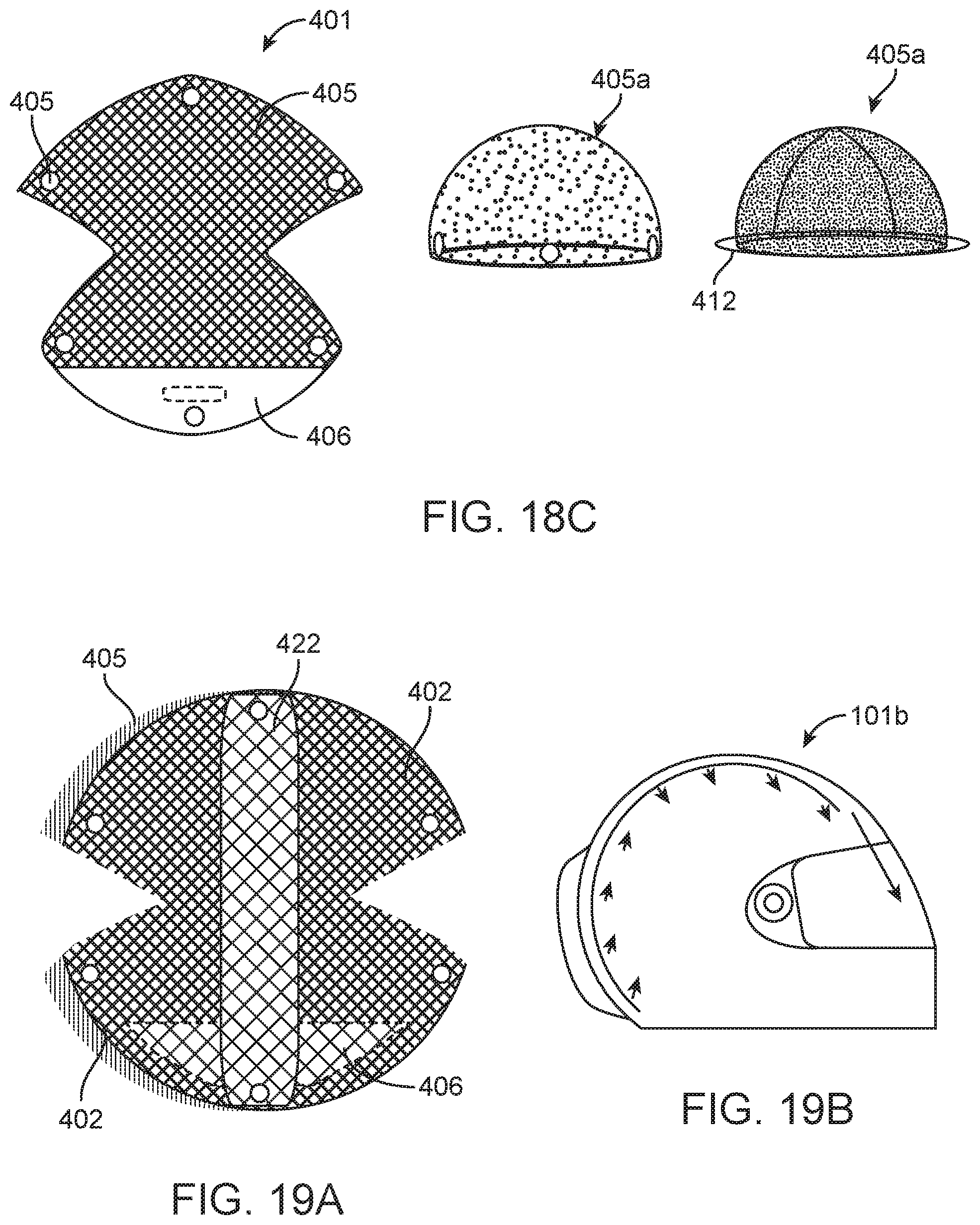
D00015

D00016

D00017

D00018
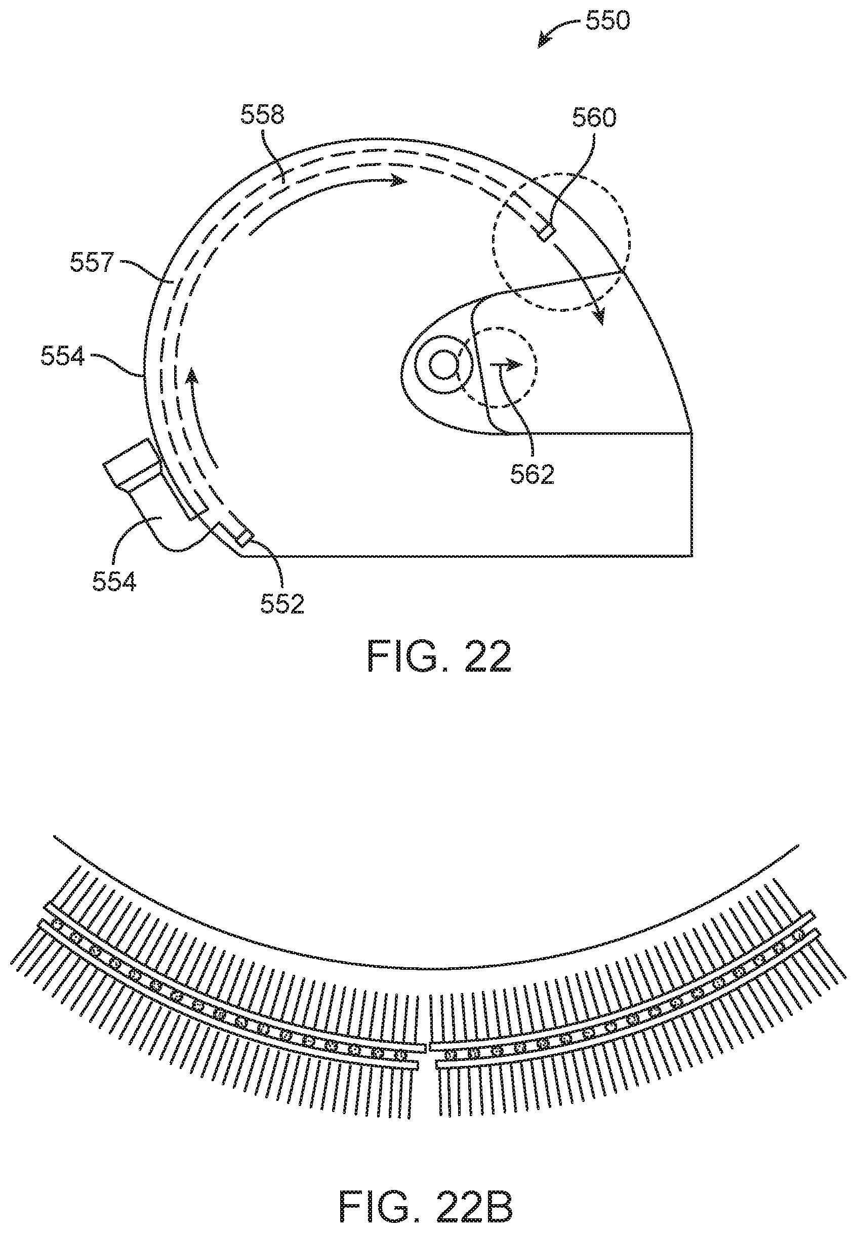
D00019
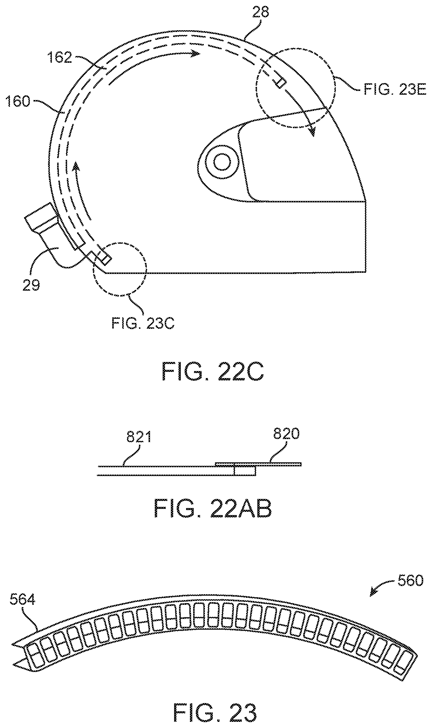
D00020
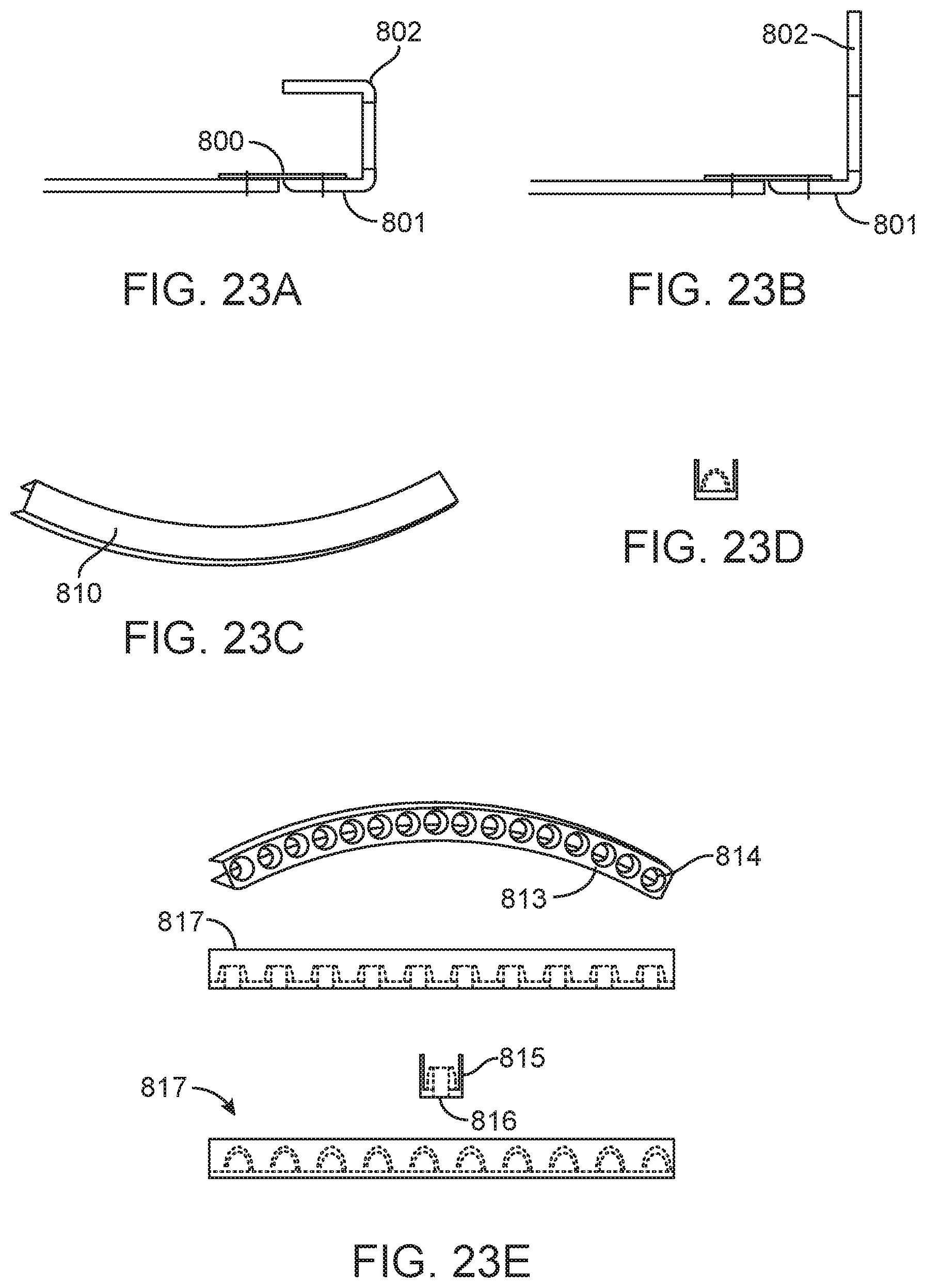
D00021

D00022

D00023

D00024

D00025
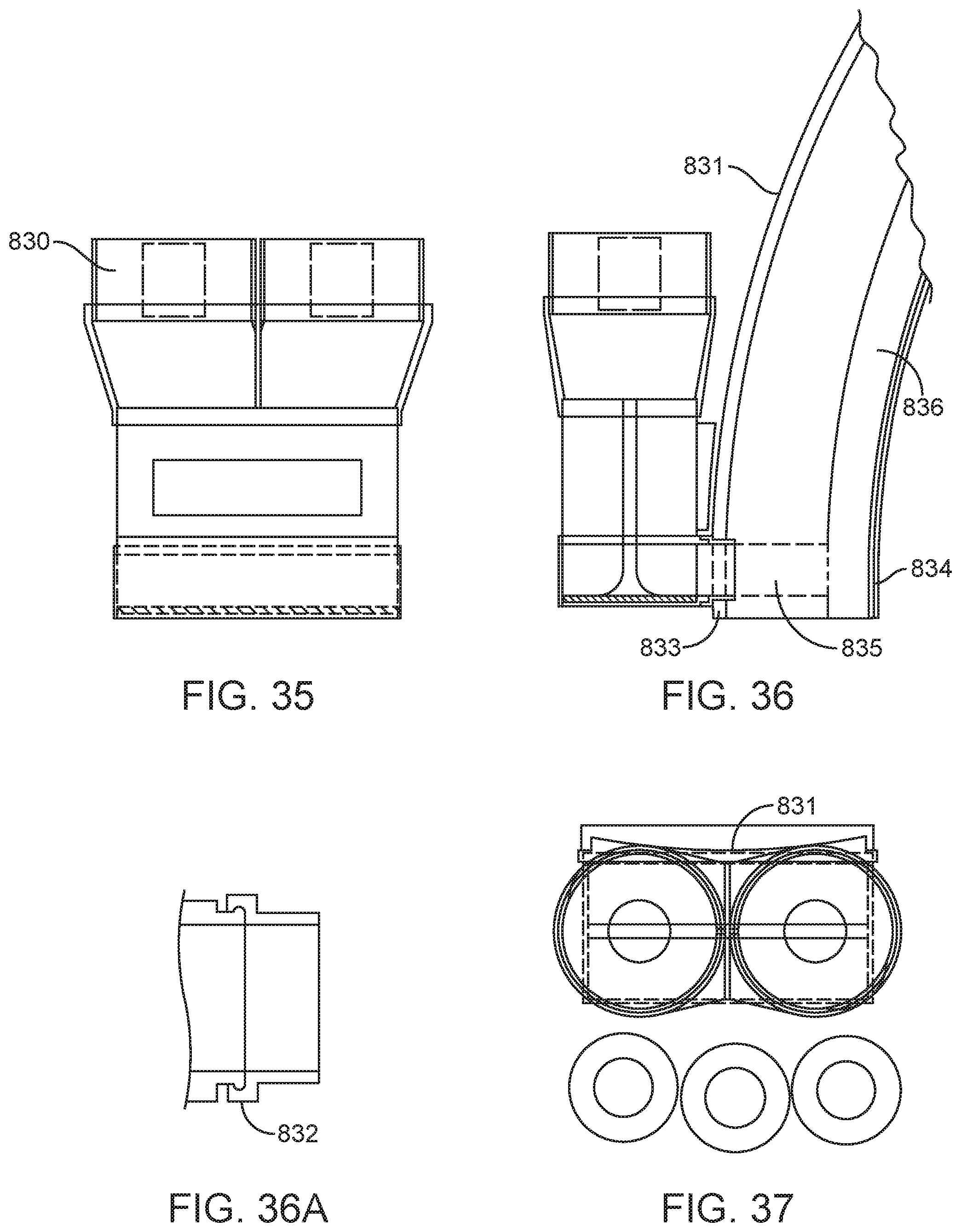
D00026
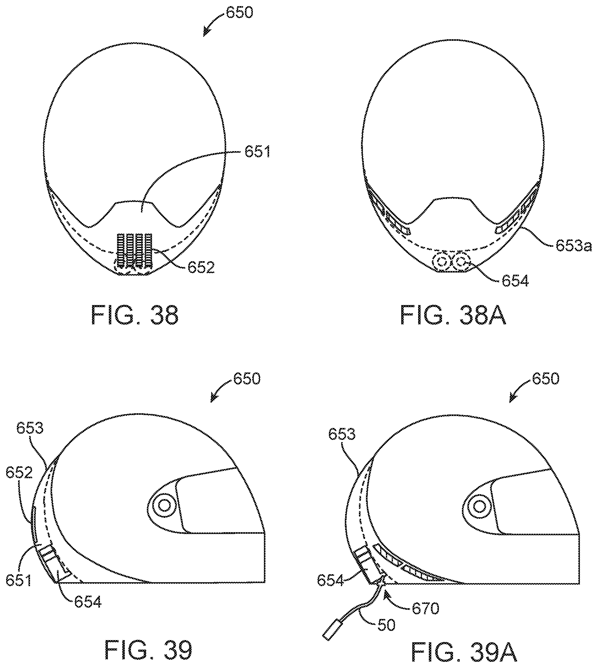
D00027
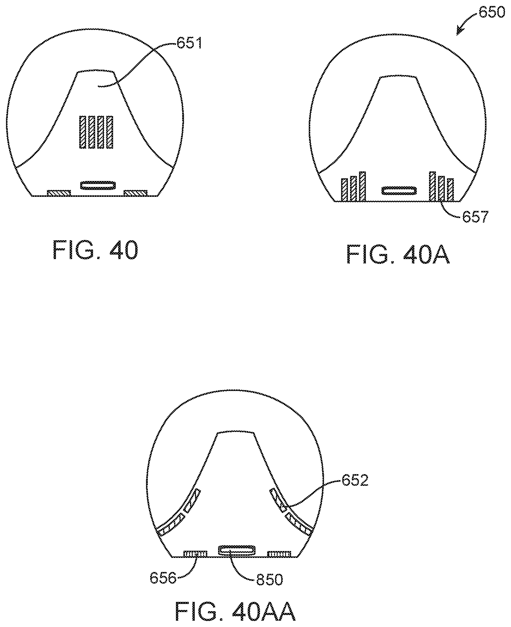
D00028
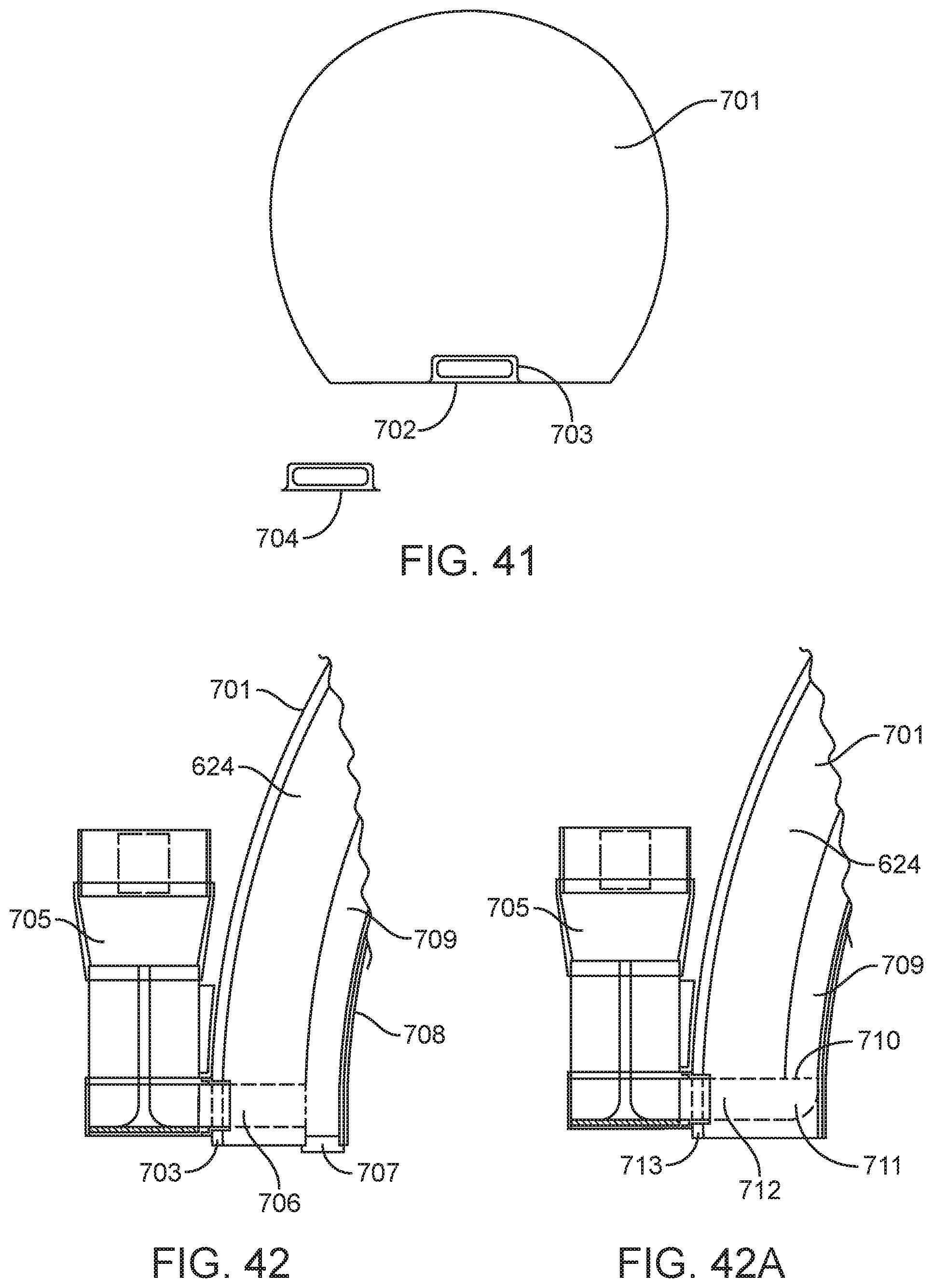
D00029

D00030
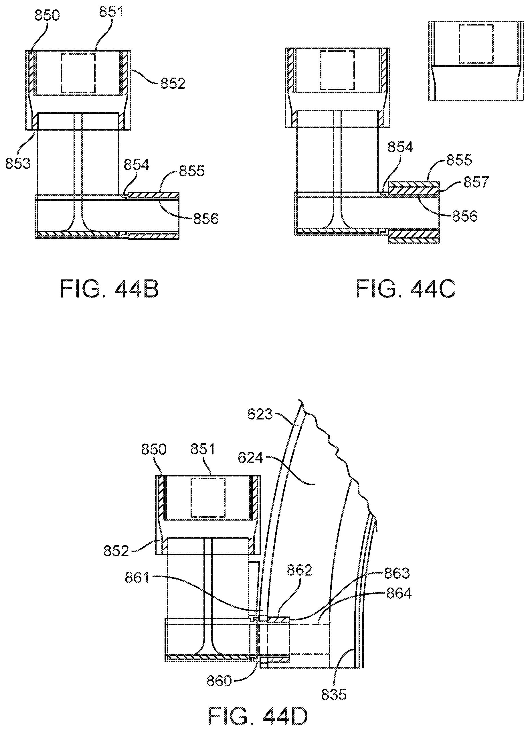
D00031

D00032
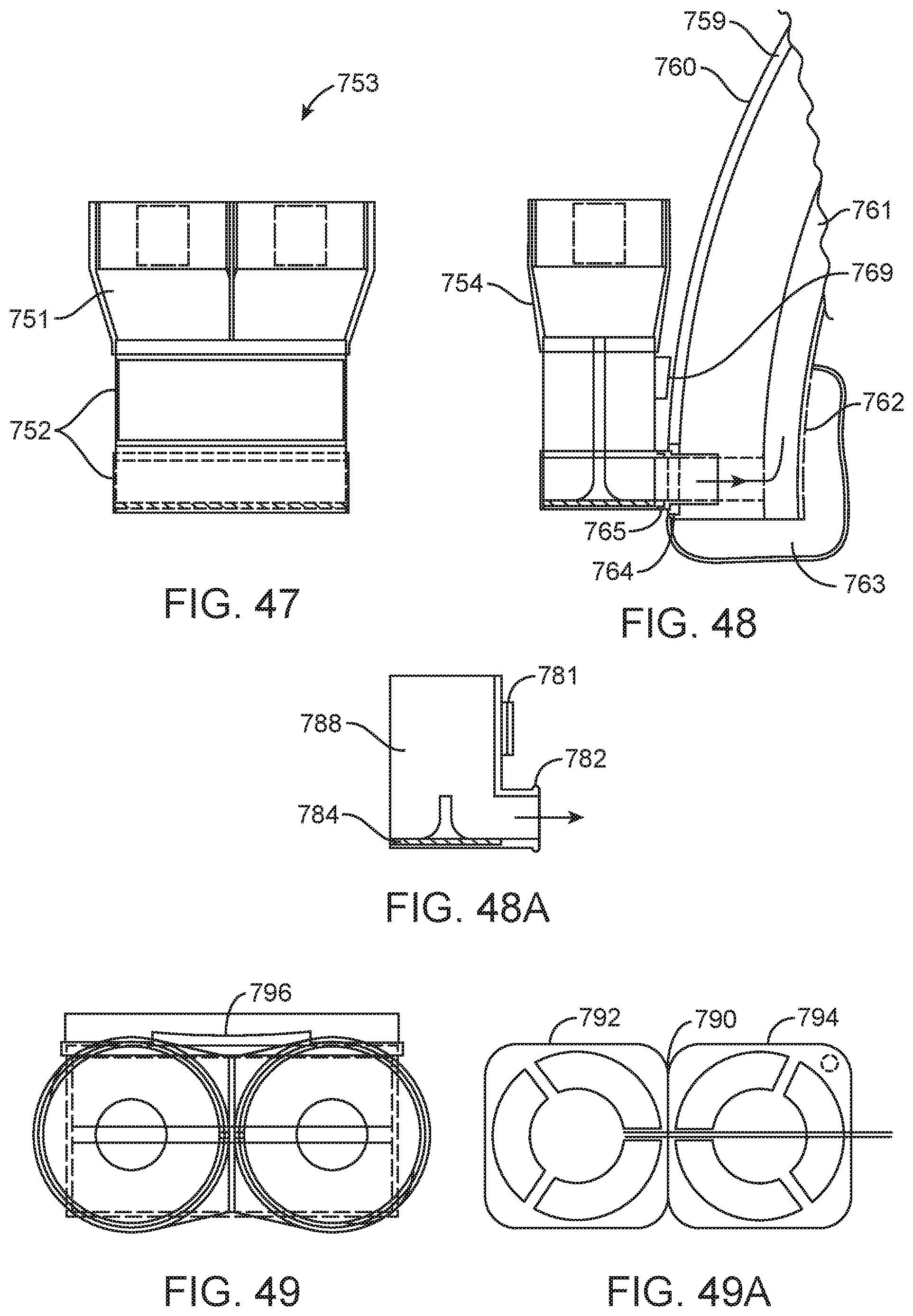
D00033
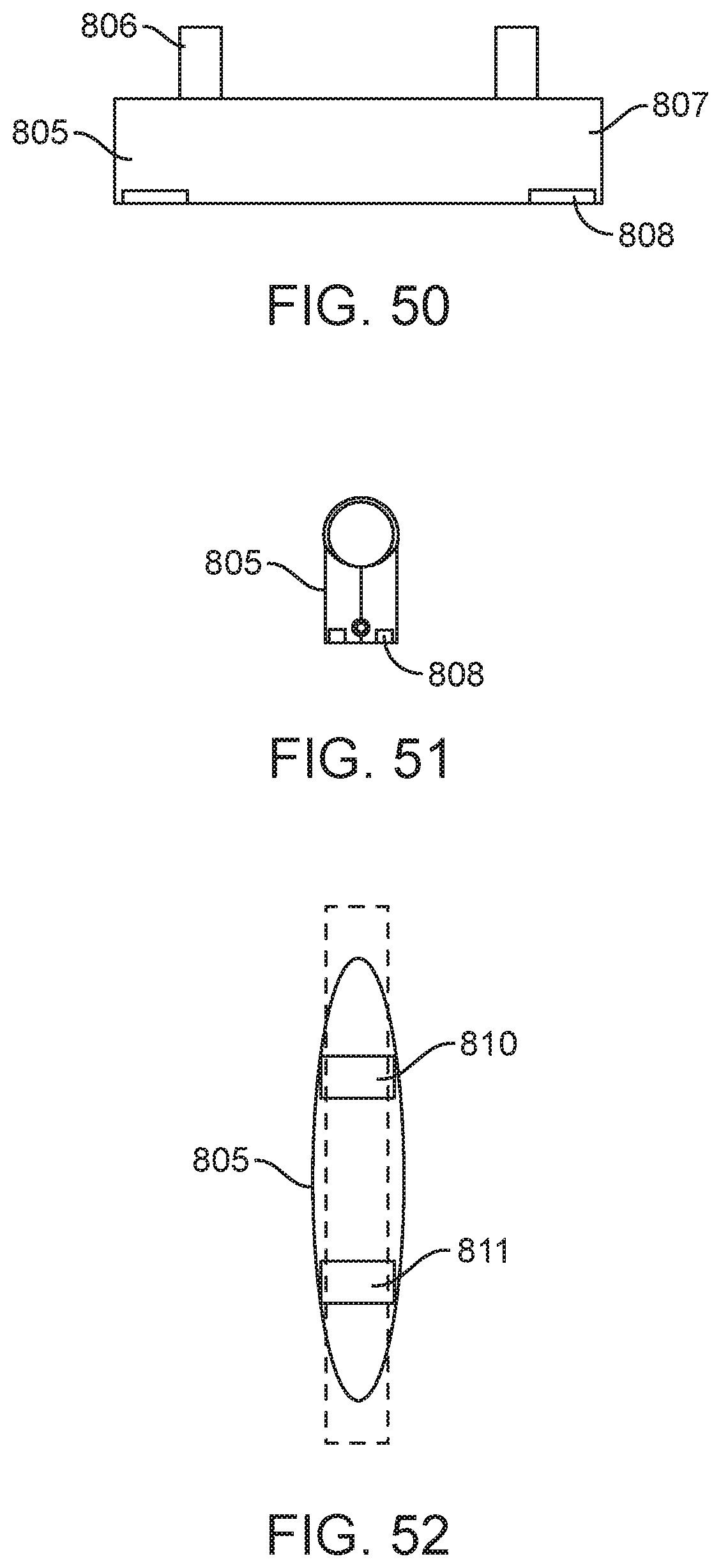
D00034
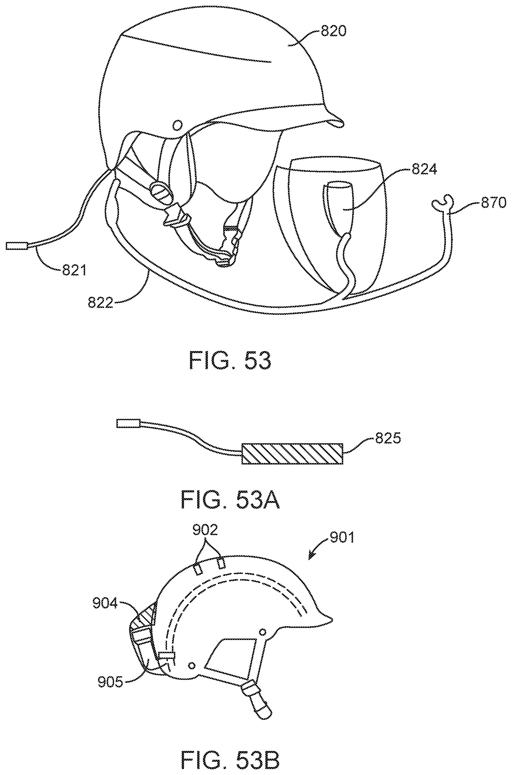
D00035
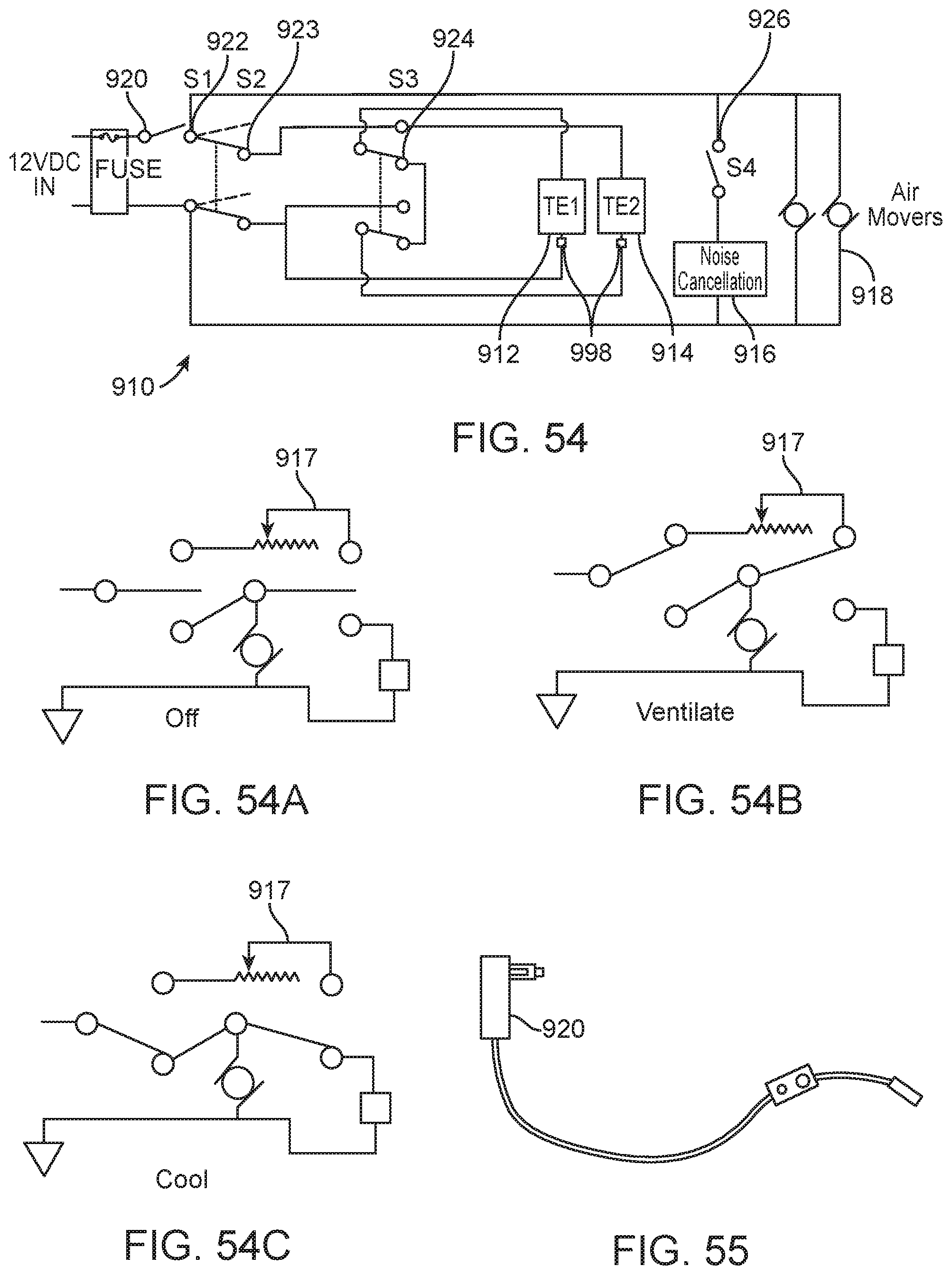
D00036
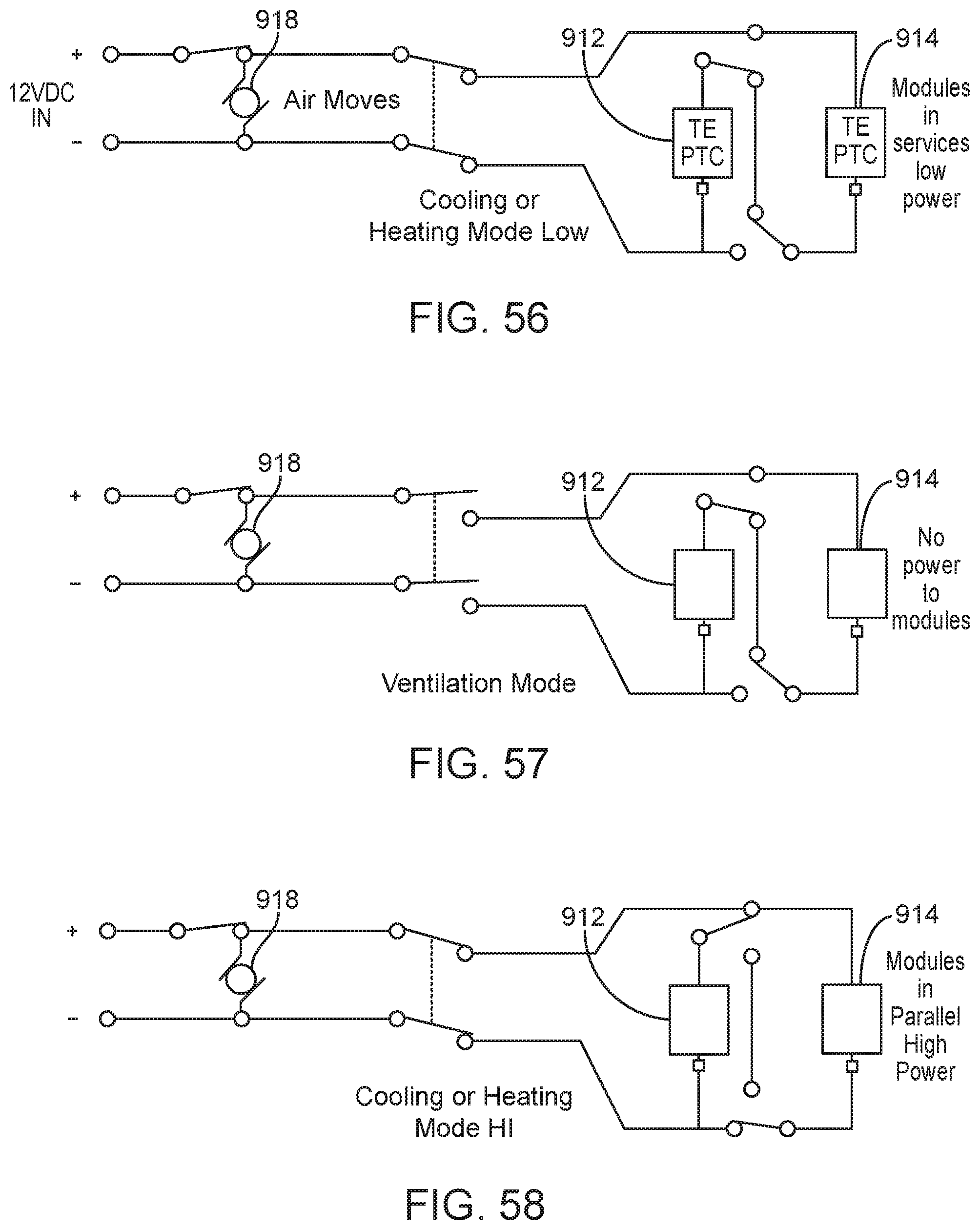
D00037

D00038

D00039

D00040
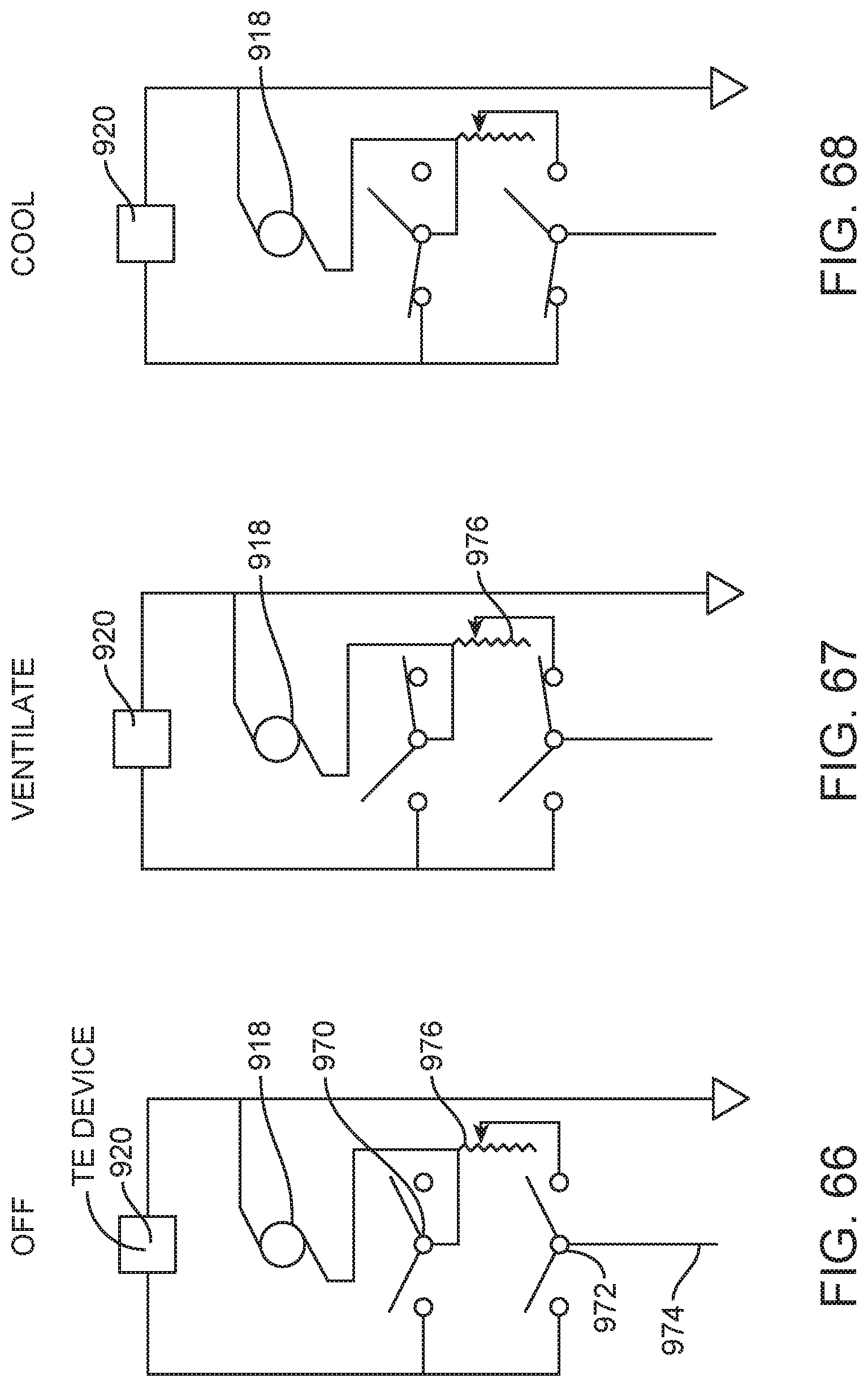
D00041
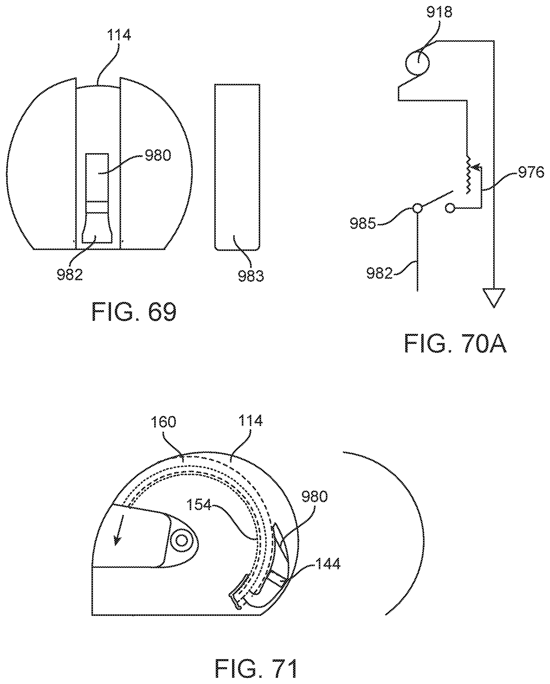
D00042
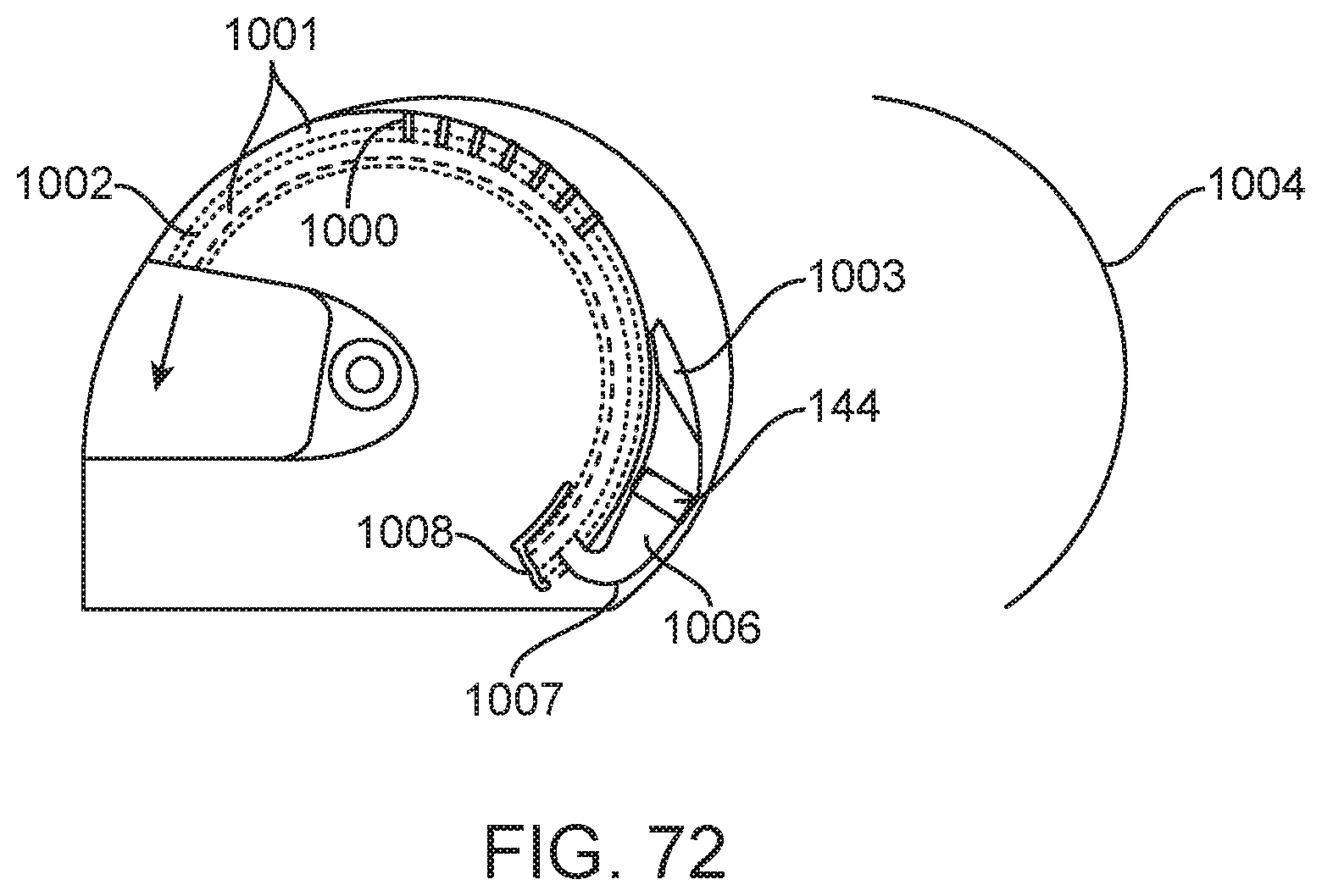
D00043

D00044
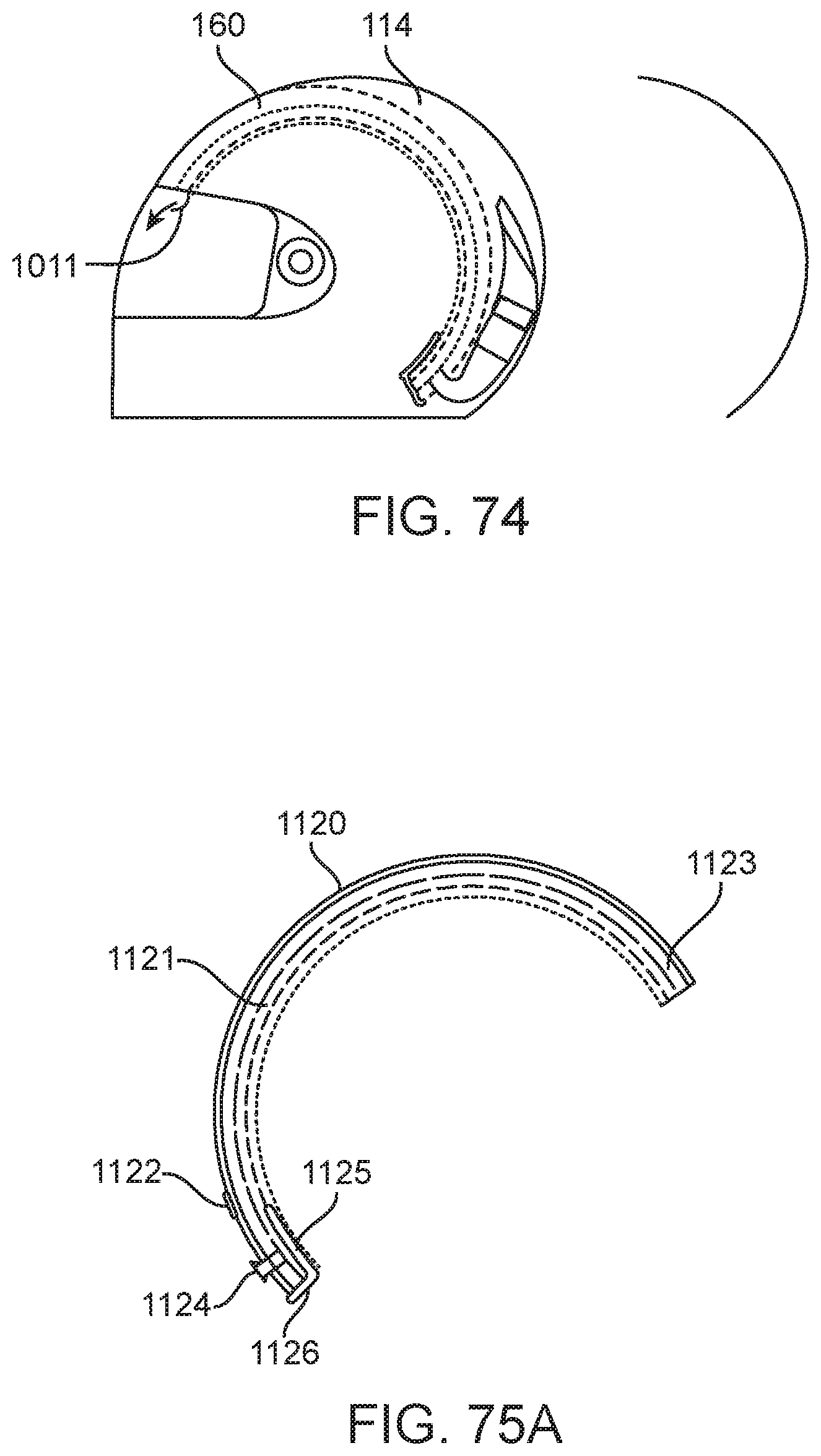
D00045

D00046
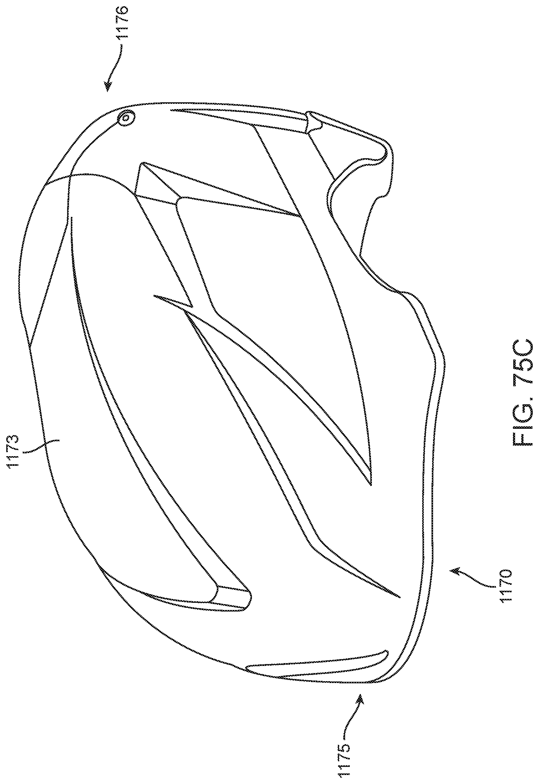
D00047
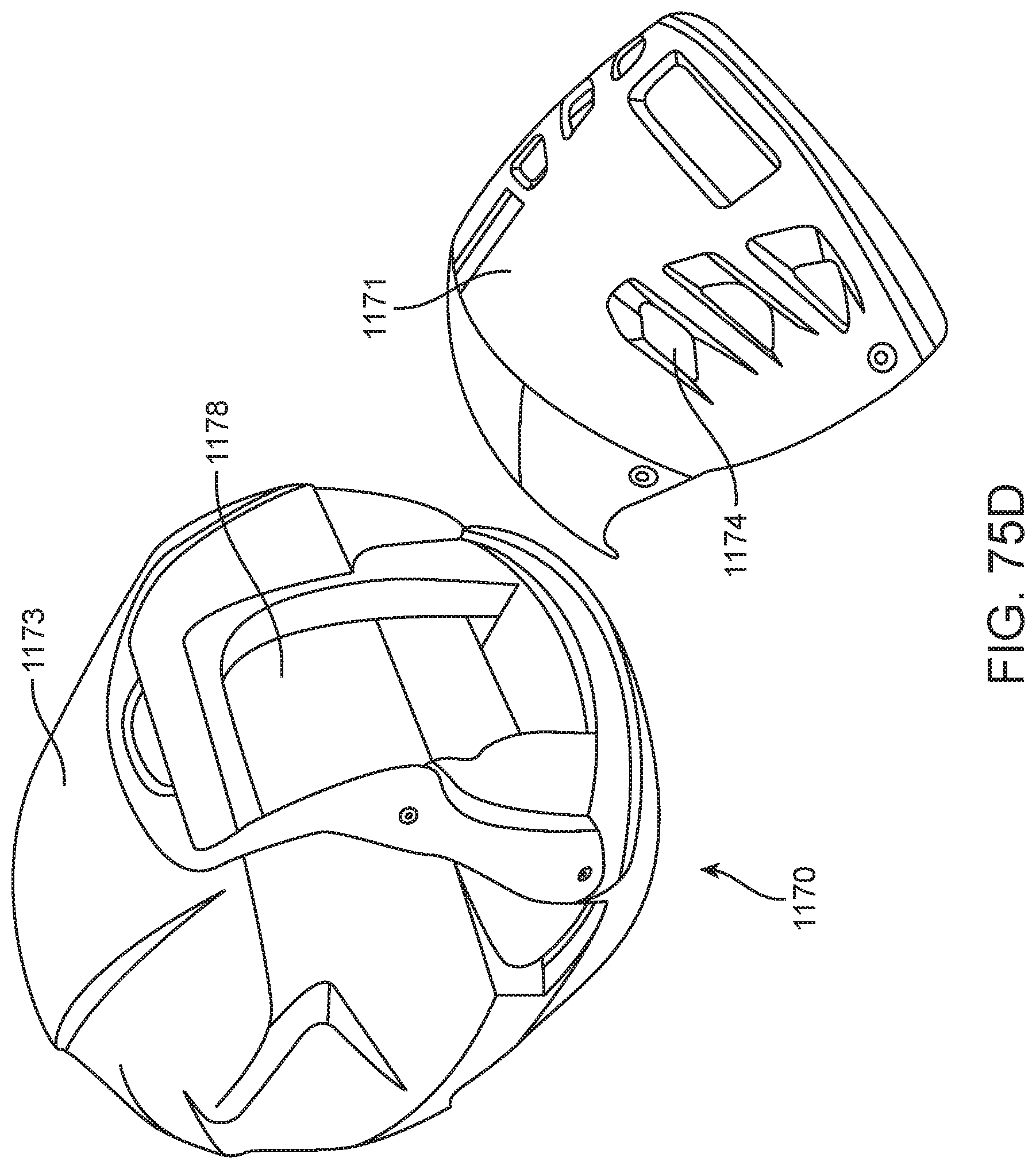
D00048

D00049
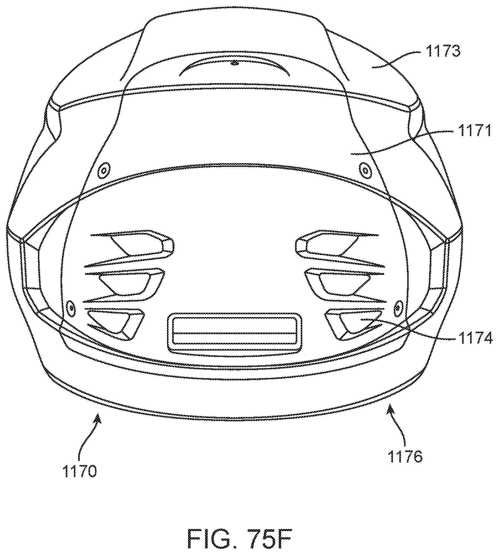
D00050

D00051

D00052

D00053
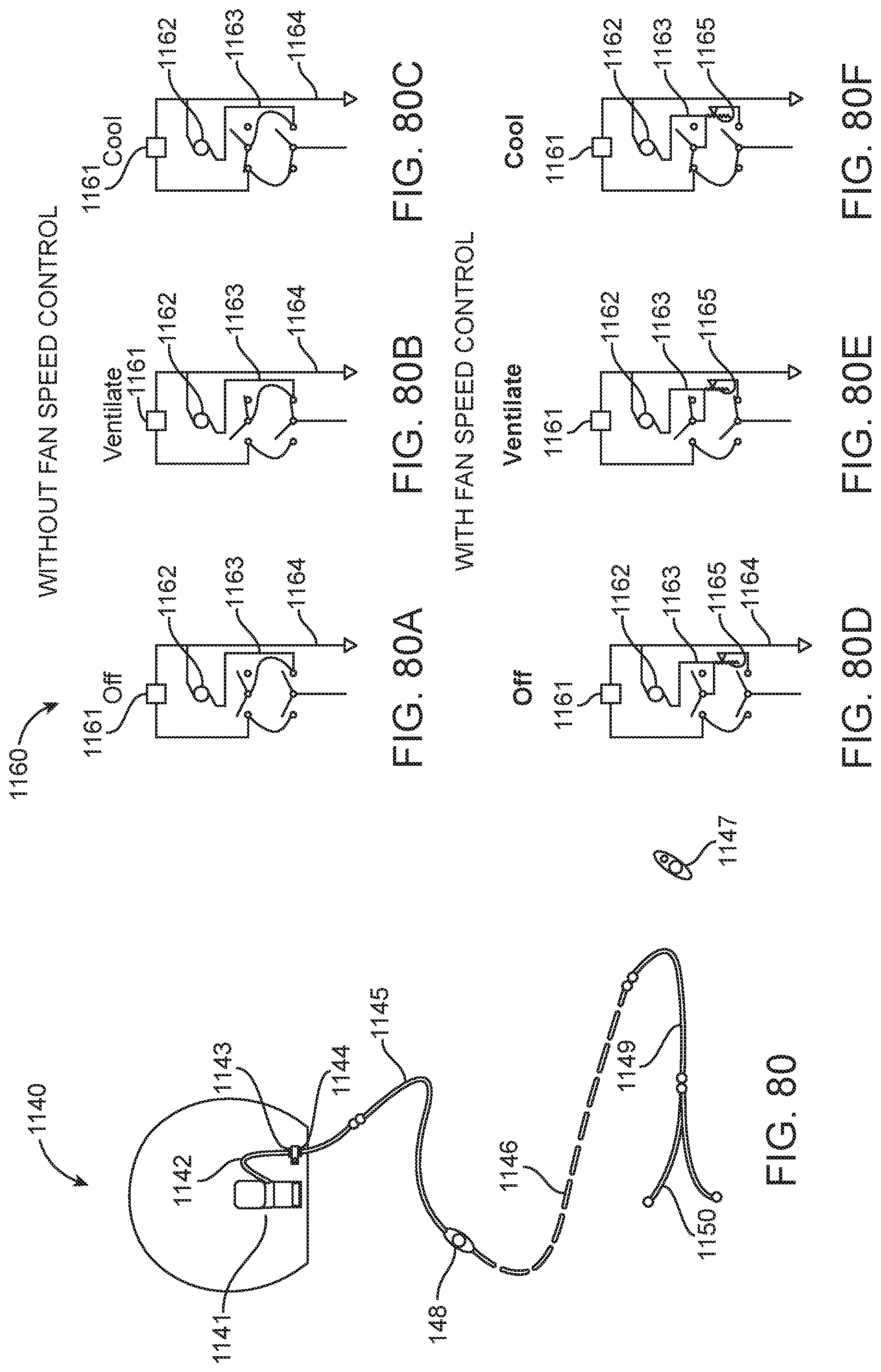
D00054
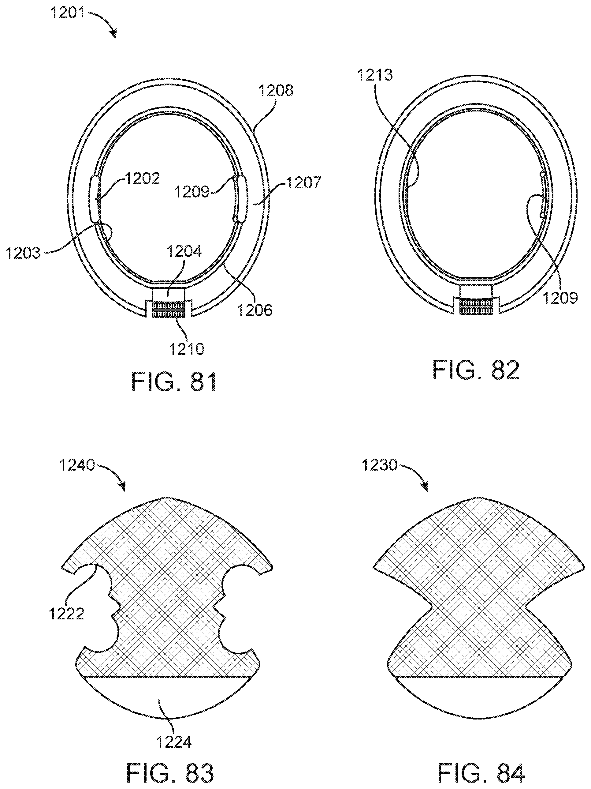
D00055

D00056

D00057
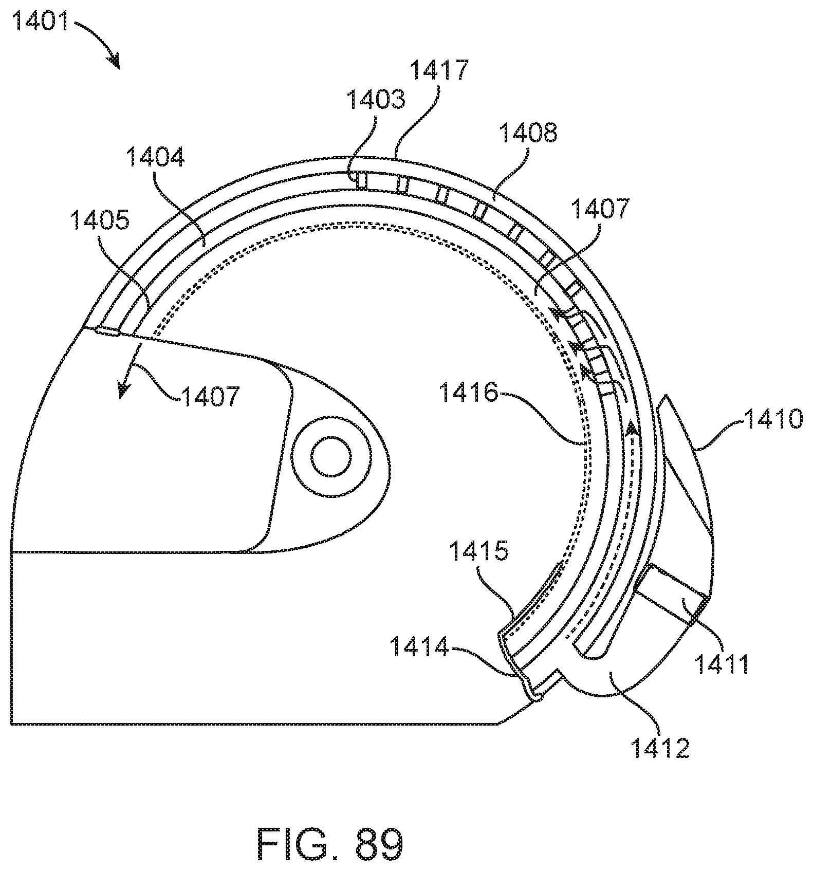
D00058

D00059
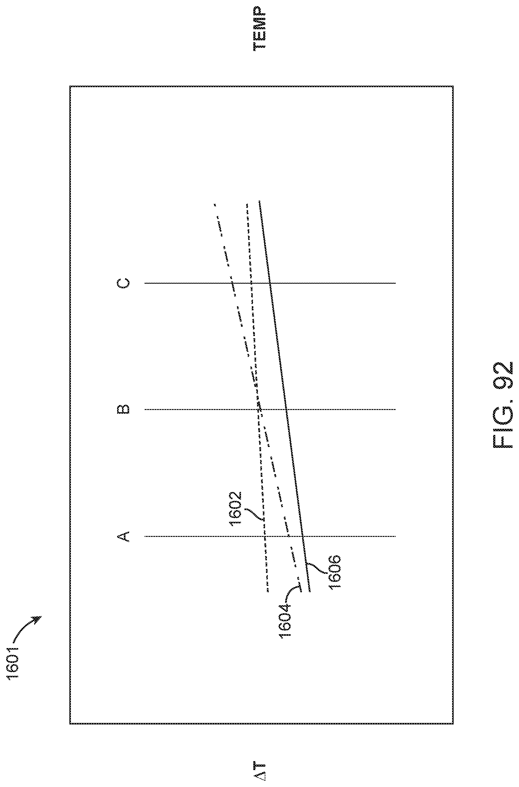
D00060

XML
uspto.report is an independent third-party trademark research tool that is not affiliated, endorsed, or sponsored by the United States Patent and Trademark Office (USPTO) or any other governmental organization. The information provided by uspto.report is based on publicly available data at the time of writing and is intended for informational purposes only.
While we strive to provide accurate and up-to-date information, we do not guarantee the accuracy, completeness, reliability, or suitability of the information displayed on this site. The use of this site is at your own risk. Any reliance you place on such information is therefore strictly at your own risk.
All official trademark data, including owner information, should be verified by visiting the official USPTO website at www.uspto.gov. This site is not intended to replace professional legal advice and should not be used as a substitute for consulting with a legal professional who is knowledgeable about trademark law.