Cleaning Gloves With Drip Protection
NEAL; Ryan
U.S. patent application number 16/742318 was filed with the patent office on 2020-07-23 for cleaning gloves with drip protection. The applicant listed for this patent is IMPAX MARKETING LLC. Invention is credited to Ryan NEAL.
| Application Number | 20200229521 16/742318 |
| Document ID | / |
| Family ID | 71609374 |
| Filed Date | 2020-07-23 |

| United States Patent Application | 20200229521 |
| Kind Code | A1 |
| NEAL; Ryan | July 23, 2020 |
CLEANING GLOVES WITH DRIP PROTECTION
Abstract
A representative cleaning glove includes: a body extending between a proximal end and a distal end, the body defining an interior cavity and an opening, the opening being positioned at the proximal end and communicating with the interior cavity, the body having a hand portion positioned at the distal end, an arm portion positioned at the proximal end, and a wrist portion positioned between the hand portion and the arm portion, the opening being configured to receive therethrough a hand of a user, and the interior cavity being configured to receive therein the hand of the user such that the hand is positioned within the hand portion of the body; a plurality of protrusions extending outwardly from the hand portion; and a cuff positioned about the arm portion, the cuff defining about the arm portion of the body an annular channel configured to reduce an amount of liquid from flowing from the exterior of the body and onto the arm of the user, the annular channel being open towards the distal end of the body.
| Inventors: | NEAL; Ryan; (Portland, OR) | ||||||||||
| Applicant: |
|
||||||||||
|---|---|---|---|---|---|---|---|---|---|---|---|
| Family ID: | 71609374 | ||||||||||
| Appl. No.: | 16/742318 | ||||||||||
| Filed: | January 14, 2020 |
Related U.S. Patent Documents
| Application Number | Filing Date | Patent Number | ||
|---|---|---|---|---|
| 62794023 | Jan 18, 2019 | |||
| Current U.S. Class: | 1/1 |
| Current CPC Class: | A41D 19/0044 20130101; A47L 13/18 20130101; A46B 5/04 20130101; A41D 19/01 20130101 |
| International Class: | A41D 19/00 20060101 A41D019/00; A46B 5/04 20060101 A46B005/04; A47L 13/18 20060101 A47L013/18; A41D 19/01 20060101 A41D019/01 |
Claims
1. A cleaning glove for wear by a user, the cleaning glove comprising: a body extending between a proximal end and a distal end, the body defining an interior cavity and an opening, the opening being positioned at the proximal end and communicating with the interior cavity, the body having a hand portion positioned at the distal end, an arm portion positioned at the proximal end, and a wrist portion positioned between the hand portion and the arm portion, the opening being configured to receive therethrough a hand of a user, and the interior cavity being configured to receive therein the hand of the user such that the hand is positioned within the hand portion of the body; a plurality of protrusions extending outwardly from the hand portion; and a cuff positioned about the arm portion, the cuff defining about the arm portion of the body an annular channel configured to reduce an amount of liquid from flowing from the exterior of the body and onto the arm of the user, the annular channel being open towards the distal end of the body.
2. The cleaning glove of claim 1, further comprising an annular ridge, positioned between the cuff and the distal end, extending about the exterior of the body, the annular ridge being configured to deflect liquid flowing toward the proximal end outwardly from the exterior of the body.
3. The cleaning glove of claim 2, further comprising an elongated recess, positioned between the annular ridge and the distal end, extending about the exterior of the body, the elongated recess being configured to enhance flexibility of the body about the elongated recess.
4. The cleaning glove of claim 3, wherein: the elongated recess is a first elongated recess; and the cleaning glove further comprises a second elongated recess, positioned between the first elongated recess and the distal end, extending about the exterior of the body.
5. The cleaning glove of claim 3, wherein the elongated recess is positioned between the annular ridge and the plurality of protrusions.
6. The cleaning glove of claim 3, wherein: the annular ridge is a first annular ridge; and the cleaning glove further comprises a second annular ridge, positioned between the first annular ridge and the distal end, extending about the exterior of the body.
7. The cleaning glove of claim 6, wherein the second annular ridge is positioned between the first annular ridge and the plurality of protrusions.
8. The cleaning glove of claim 7, wherein the second annular ridge is positioned between the first annular ridge and the elongated recess.
9. The cleaning glove of claim 7, wherein the second annular ridge is positioned between the first annular ridge and the wrist portion.
10. The cleaning glove of claim 3, wherein the plurality of protrusions has a first set of protrusions of a first shape and a second set of protrusions of a second shape different than the first shape.
11. The cleaning glove of claim 3, wherein: the plurality of protrusions has a first set of protrusions extending a first distance from the exterior of the body and a second set of protrusions extending a second distance from the exterior of the body; and the first distance is different than the second distance.
12. The cleaning glove of claim 1, wherein: the cuff has a flange and a wall segment; the flange is annular in shape and extends outwardly from an exterior surface of the body; and the wall segment extends outwardly from the flange and toward the distal end.
13. The cleaning glove of claim 1, further comprising a hand-engagement feature positioned within the interior cavity configured to position the hand of the user within the interior cavity.
14. The cleaning glove of claim 13, wherein the hand-engagement feature is formed by a thickened portion of the body.
15. The cleaning glove of claim 14, wherein: the hand-engagement feature is a first hand-engagement feature; the cleaning glove further comprises a second hand-engagement feature; and the first hand-engagement feature and the second hand-engagement feature are disposed on opposing interior sides of the body.
16. The cleaning glove of claim 1, further comprising a finger-engagement feature positioned within the interior cavity, the finger-engagement feature defining a finger slot configured to receive a finger of the user.
Description
CROSS REFERENCE TO RELATED APPLICATION
[0001] This utility application claims the benefit of and priority to U.S. Provisional Application 62/794,023, filed on 18 Jan. 2019, which is incorporated herein by reference in its entirety.
BACKGROUND
Technical Field
[0002] The disclosure generally relates to cleaning devices.
Description of the Related Art
[0003] Various cleaning devices are available that incorporate features for facilitating cleaning. By way of example, some of these devices incorporate brushes that are relatively efficient for use in scrubbing an item that is to be cleaned. During use of such a device, a cleaning solvent is frequently used. Depending on the type of cleaning solvent and/or user preference, a glove may be worn to prevent the cleaning solvent from contacting the user. Unfortunately, the cleaning solvent oftentimes has a tendency to drip onto the user's arm as the user moves and articulates their arm/hand.
[0004] Therefore, it is desirable to provide a cleaning device that addresses the aforementioned perceived need.
SUMMARY
[0005] An example embodiment of a cleaning glove for wear by a user comprises: a body extending between a proximal end and a distal end, the body defining an interior cavity and an opening, the opening being positioned at the proximal end and communicating with the interior cavity, the body having a hand portion positioned at the distal end, an arm portion positioned at the proximal end, and a wrist portion positioned between the hand portion and the arm portion, the opening being configured to receive therethrough a hand of a user, and the interior cavity being configured to receive therein the hand of the user such that the hand is positioned within the hand portion of the body; a plurality of protrusions extending outwardly from the hand portion; and a cuff positioned about the arm portion, the cuff defining about the arm portion of the body an annular channel configured to reduce an amount of liquid from flowing from the exterior of the body and onto the arm of the user, the annular channel being open towards the distal end of the body.
[0006] In some embodiments, an annular ridge, positioned between the cuff and the distal end, extends about the exterior of the body, the annular ridge being configured to deflect liquid flowing toward the proximal end outwardly from the exterior of the body.
[0007] In some embodiments, an elongated recess, positioned between the annular ridge and the distal end, extends about the exterior of the body, the elongated recess being configured to enhance flexibility of the body about the elongated recess.
[0008] In some embodiments, the elongated recess is a first elongated recess; and the cleaning glove further comprises a second elongated recess, positioned between the first elongated recess and the distal end, extending about the exterior of the body.
[0009] In some embodiments, the elongated recess is positioned between the annular ridge and the plurality of protrusions.
[0010] In some embodiments, the annular ridge is a first annular ridge; and the cleaning glove further comprises a second annular ridge, positioned between the first annular ridge and the distal end, extending about the exterior of the body.
[0011] In some embodiments, the second annular ridge is positioned between the first annular ridge and the plurality of protrusions.
[0012] In some embodiments, the second annular ridge is positioned between the first annular ridge and the elongated recess.
[0013] In some embodiments, the second annular ridge is positioned between the first annular ridge and the wrist portion.
[0014] In some embodiments, the plurality of protrusions has a first set of protrusions of a first shape and a second set of protrusions of a second shape different than the first shape.
[0015] In some embodiments, the plurality of protrusions has a first set of protrusions extending a first distance from the exterior of the body and a second set of protrusions extending a second distance from the exterior of the body; and the first distance is different than the second distance.
[0016] In some embodiments, the cuff has a flange and a wall segment; the flange is annular in shape and extends outwardly from an exterior surface of the body; and the wall segment extends outwardly from the flange and toward the distal end.
[0017] In some embodiments, a hand-engagement feature is positioned within the interior cavity configured to position the hand of the user within the interior cavity.
[0018] In some embodiments, the hand-engagement feature is formed by a thickened portion of the body.
[0019] In some embodiments, the hand-engagement feature is a first hand-engagement feature; the cleaning glove further comprises a second hand-engagement feature; and the first hand-engagement feature and the second hand-engagement feature are disposed on opposing interior sides of the body.
[0020] In some embodiments, a finger-engagement feature is positioned within the interior cavity, the finger-engagement feature defining a finger slot configured to receive a finger of the user.
[0021] Other objects, features, and/or advantages will become apparent from the following detailed description of the preferred but non-limiting embodiments. The following description is made with reference to the accompanying drawings.
BRIEF DESCRIPTION OF THE DRAWINGS
[0022] FIG. 1 is a schematic diagram of an embodiment of a cleaning glove.
[0023] FIG. 2 is a schematic diagram of the embodiment of FIG. 1.
[0024] FIG. 3 is a schematic, cross-sectional view of a portion of the embodiment of FIG. 1 as viewed along section line 3-3.
[0025] FIG. 4A is a schematic, cross-sectional view of a portion of the embodiment of FIG. 1 as viewed along section line 4-4.
[0026] FIG. 4B is a schematic, cross-sectional view of a portion of another embodiment as viewed along section line 4-4 in FIG. 1.
[0027] FIG. 5 is a schematic, cross-sectional view of a portion of the embodiment of FIGS. 1 and 4B as viewed along section line 5-5 in FIG. 1.
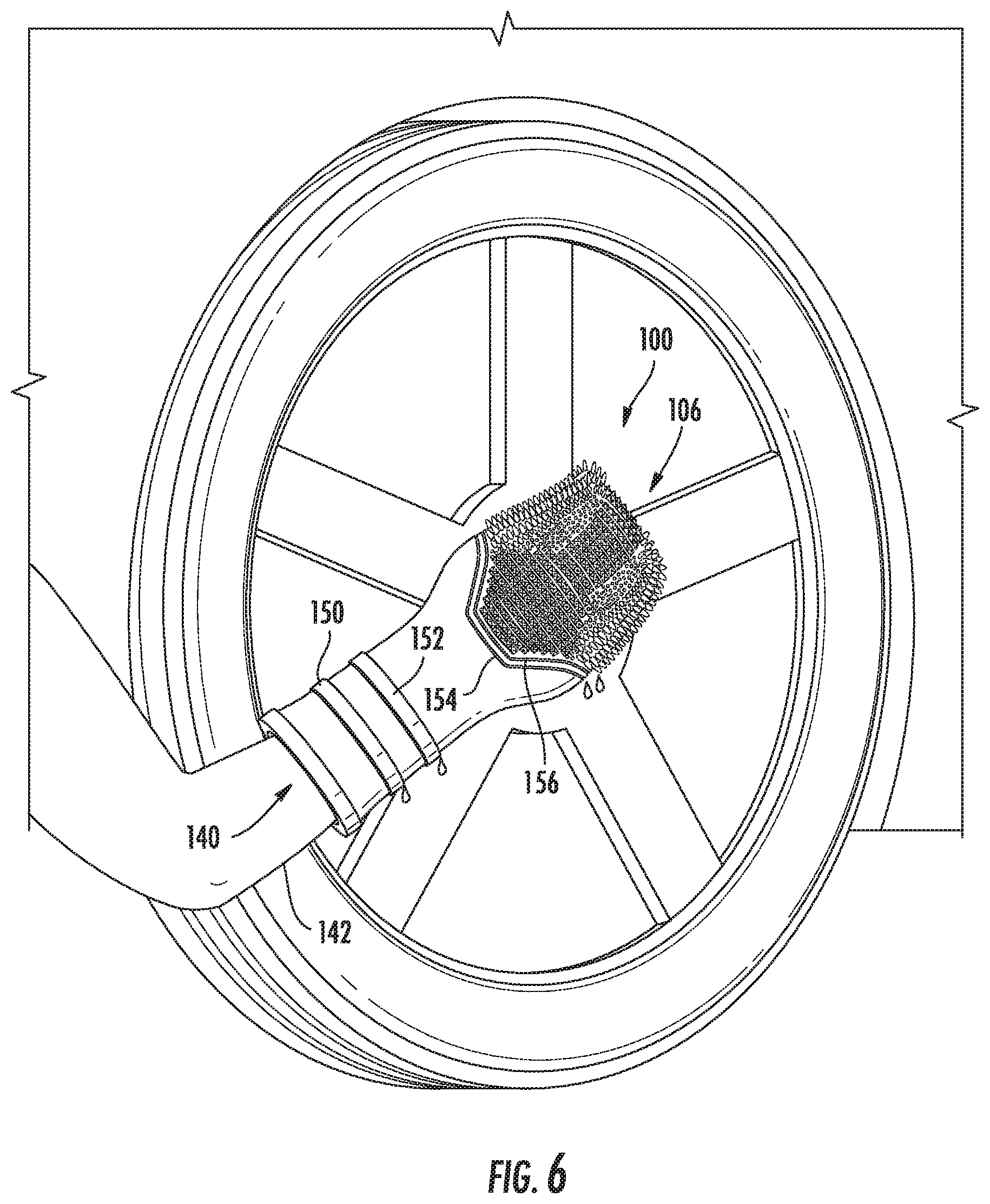
[0028] FIG. 6 is a schematic diagram of another embodiment of a cleaning glove.
DETAILED DESCRIPTION
[0029] For ease of explanation, the following describes several embodiments of cleaning gloves with drip protection that are configured to be worn by a user during cleaning. It is to be understood that the invention is not limited in its application to the details of the particular arrangements shown since the invention is capable of other embodiments. Also, the terminology used herein is for the purpose of description and not of limitation.
[0030] In this regard, various embodiments of a cleaning glove are designed for optimum usability and comfort in cleaning applications. By way of example, in some embodiments, a cleaning glove is formed of a durable yet flexible material (such as molded rubber, silicone, or the like) that not only shields the user from liquids and/or cleaning compounds, but provides a comfortable inner surface that is suitable for direct skin contact. Such a cleaning glove may also incorporate one or more unique features that are configured to reduce the amount of liquid that is able to drip from the cleaning glove and onto the user. These and other features will now be described in detail with respect to the drawings.
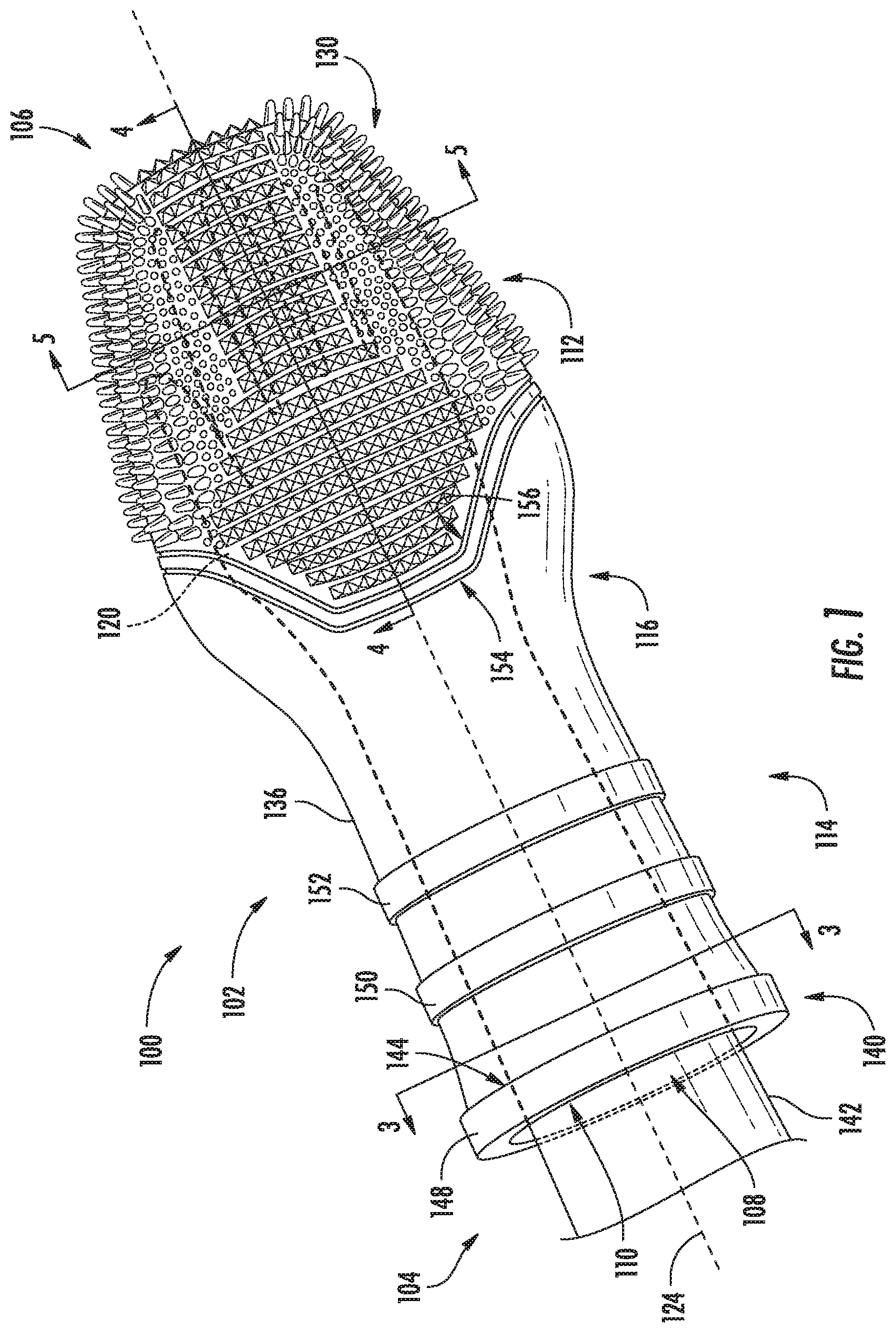
[0031] As shown in FIGS. 1 and 2, an embodiment of a cleaning glove 100 is configured for wear by a user. In particular, cleaning glove 100 incorporates a body 102 that extends between a proximal end 104 and a distal end 106. Body 102 defines an opening 108 and an interior cavity 110. Opening 108 is positioned at proximal end 104 and communicates with interior cavity 110. Body 102 includes a hand portion 112 positioned at distal end 106, an arm portion 114 positioned at proximal end 104, and a wrist portion 116 positioned between hand portion 112 and arm portion 114. Both opening 108 and interior cavity 110 are configured to receive the hand (120) of a user so that the hand may be positioned within hand portion 112. With the hand of the user so positioned, cleaning glove 100 may be oriented, moved and otherwise manipulated with the arm and hand of the user to perform various cleaning functions.
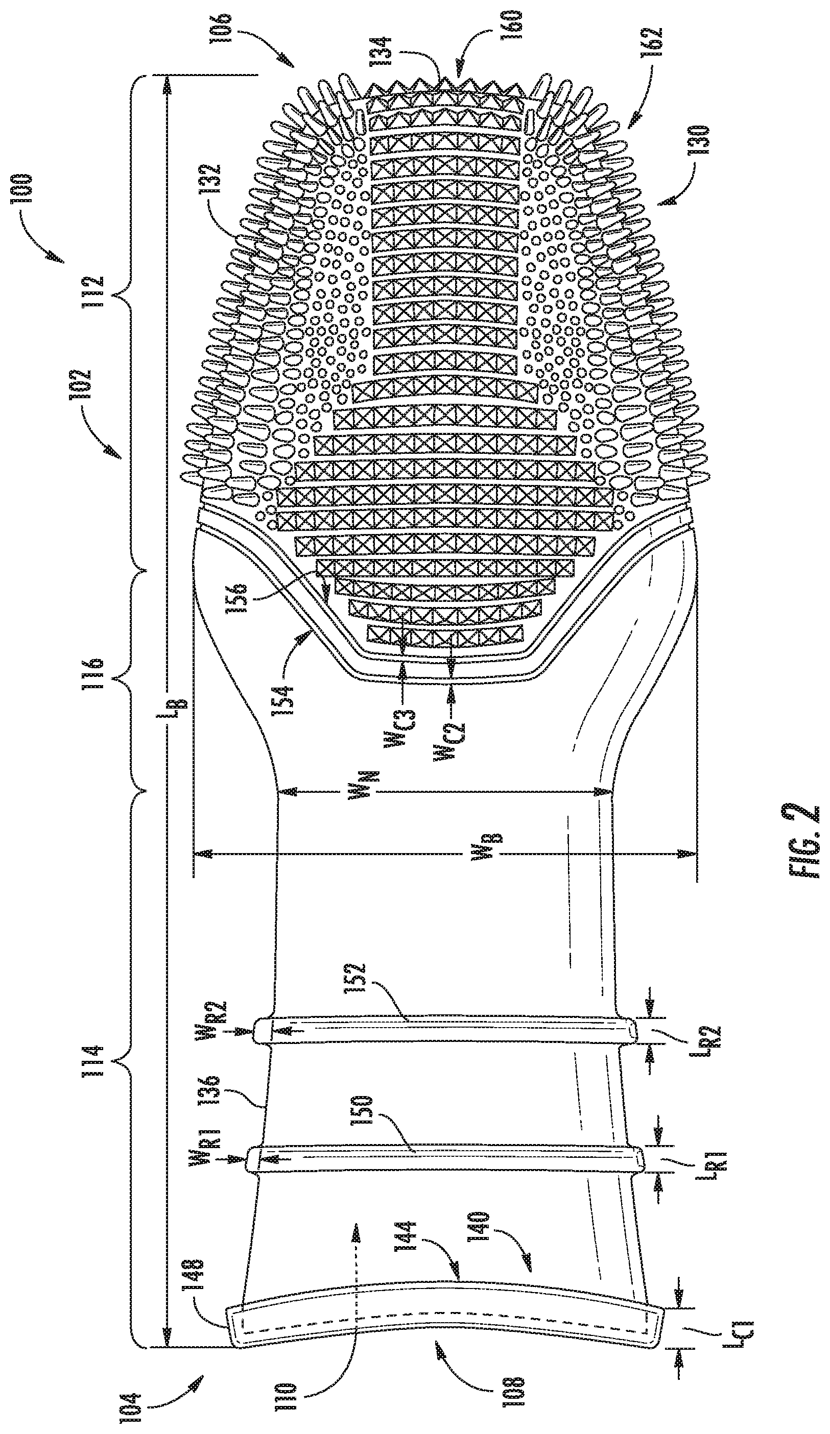
[0032] As shown in FIG. 2, body 102 extends lengthwise along a centerline 124, exhibiting a length (L.sub.B) (e.g., approximately 15 inches in some embodiments) and various widths along its length. In particular, hand portion 112 may exhibit a widest width (W.sub.B) of body 102, with a necked area of wrist portion 116 exhibiting a narrowest width (W.sub.N). In some embodiments, W.sub.B may be between approximately 4 and 7 inches, preferably between approximately 5.5 and 6.5 inches, whereas W.sub.N may be between approximately 3 and 5 inches, preferably between approximately 3.5 and 4.5 inches.
[0033] In order to enhance cleaning, a plurality of protrusions 130 (e.g., protrusion 132, 134) or nubs are provided that extend outwardly from an exterior surface 136 of body 102. Generally, the plurality of protrusions 130 extend about hand portion 112, although in some embodiments protrusions may additionally extend from other portions of body 102. The protrusions are configured to provide a frictional force to aid in cleaning and may, in some embodiments, be configured to reach into small areas. In some embodiments, the protrusions are formed of the same material as that used to form body 102 and, thus, may be flexible and tend to deflect relative to body 102 when the protrusions engage an item during cleaning. In various embodiments, the protrusions may vary in size and/or shape, which includes the use of multiple sizes and/or shapes of protrusions on a single cleaning glove.
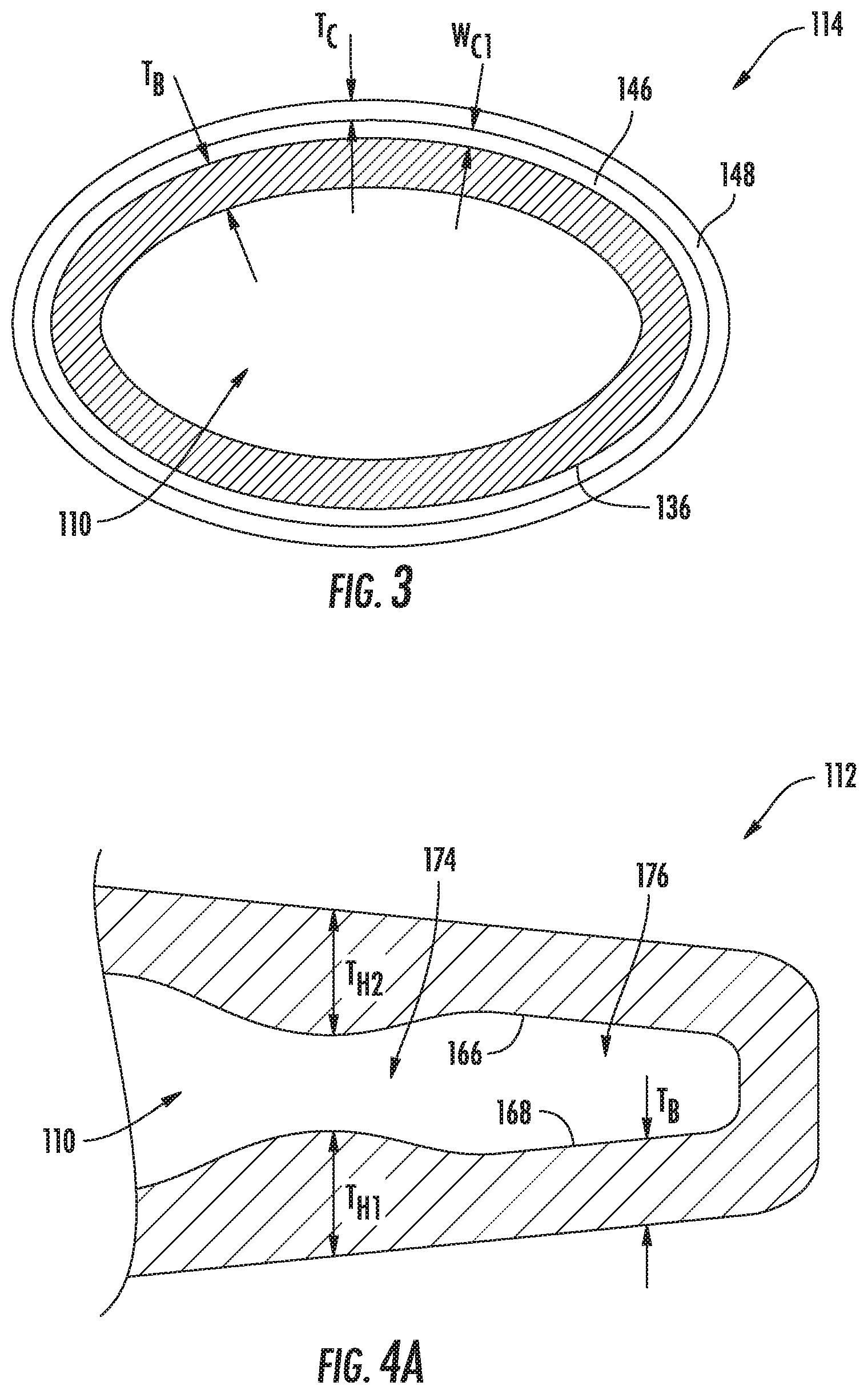
[0034] A cuff 140 (FIGS. 1-3) also is provided that is positioned about arm portion 114. Cuff 140 is configured to reduce or prevent an amount of liquid from flowing from the exterior of body 102 and onto the arm (142) of the user. Specifically, cuff 140 defines an annular channel 144 about arm portion 114 that is configured to reduce an amount of liquid from flowing from the exterior surface 136 of body 102 and onto the arm of the user. To facilitate this function, annular channel 144 is open towards distal end 106 in order to receive liquid flowing toward the proximal end. In some embodiments (see FIG. 3), cuff 140 incorporates a flange 146 that is annular in shape and extends outwardly from exterior surface 136. Cuff 140 also incorporates a wall segment 148 that extends outwardly from the flange and toward distal end 106. Annular channel 144 (FIG. 2) exhibits a length (or depth) (L.sub.C1) of between approximately 0.25 and 1.0 inches, preferably between approximately 0.5 and 0.75 inches. In some embodiments, more than one cuff may be provided. By way of example, one or more of the protrusions may be configured as a cuff (which defines an annular channel).
[0035] As shown in FIG. 3, annular channel 144 exhibits a width (W.sub.C1) of between approximately 0.0625 and 0.5 inches, preferably between approximately 0.125 and 0.5 inches. Additionally, wall segment 148 exhibits a thickness (T.sub.C) of between approximately 0.03125 and 0.1875 inches, preferably between approximately 0.0625 and 0.125 inches, whereas body 102 in a vicinity of cuff 140 exhibits a thickness (T.sub.B) of between approximately 0.0625 and 0.1875 inches.
[0036] In some embodiments, an annular ridge 150 is positioned between cuff 140 and distal end 106. Annular ridge 150 extends outwardly from and about exterior 136 of body 102 and is configured to deflect liquid outwardly and away from body 102. As shown in FIGS. 1 and 2, more than one annular ridge may be provided in some embodiments, with a second annular ridge 152 being positioned between annular ridge 150 and distal end 106. More specifically, annular ridge 152 is positioned between annular ridge 150 and the plurality of protrusions 130. In some of these embodiments, annular ridge 152 is positioned between annular ridge 150 and the boundary between arm portion 114 and wrist portion 116.
[0037] In some embodiments, an elongated recess 154 is positioned between annular ridge 150 and distal end 106 that extends about exterior surface 136 of body 102. Elongated recess 154, which may be a continuous recess in some embodiments, is configured to enhance flexibility of body 102 to facilitate ease of use. It should be noted that, in some embodiments, the second annular ridge (152) is positioned between the first annular ridge (150) and elongated recess 154. As is also shown in FIGS. 1 and 2, more than one elongated recess may be provided in some embodiments, with a second elongated recess (156) being positioned between elongated recess 154 and distal end 106. More specifically, elongated recess 156 is positioned between elongated recess 154 and the plurality of protrusions 130.
[0038] As mentioned above, the plurality of protrusions 130 may vary in size and/or shape in various embodiments. With reference back to FIG. 2, the plurality of protrusions 130 of this embodiment include a first set of protrusions 160 of a first shape and a second set of protrusions 162 of a different second shape. In particular, each of the protrusions of the first set of protrusions 160 exhibits a pyramidal shape, while each of the protrusions of the second set of protrusions 162 exhibits the shape of a triangular tab. Additionally, or alternatively, in some embodiments, the plurality of protrusions 130 may extend at varied distances from exterior surface 136 of body 102. For instance, in the embodiment of FIG. 2, each of the protrusions of the first set of protrusions 160 extends a first (shorter) distance than does each of the protrusions of the second set of protrusions 162. Note also that the first set of protrusions 160 is disposed along a contiguous area of body 102, whereas the second set of protrusions 162 are disposed in two distinct areas separated by the first set of protrusions 160.
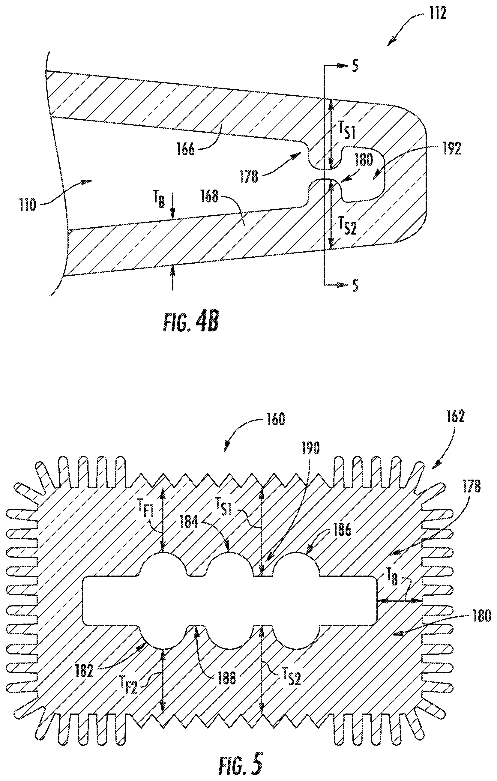
[0039] In some embodiments, wall thickness of body 102 may be varied in one or more locations to improve the usability of cleaning glove 100, such as by enhancing the user's grip. In this regard, a portion of an example embodiment that incorporates varying wall thickness is depicted in FIG. 4A. As shown, body 102 in a vicinity of hand portion 112 exhibits a nominal thickness (T.sub.B) of between approximately 0.0625 and 0.1875 inches. However, this embodiment incorporates hand-engagement features disposed on opposing interior surfaces 166, 168 that are configured to assist in positioning of a user's hand. Specifically, a first hand-engagement feature 170 that is configured to engage with the palm of a user and a second hand-engagement feature 172 that is configured to engage with the back of a user's hand are provided. Note that, in some embodiments, the hand-engagement features 170 and 172 are symmetrical to provide reversibility during use. In some embodiments, each hand-engagement feature exhibits a thickness (T.sub.H1 and/or T.sub.H2) of between approximately 0.125 and 0.75 inches, preferably between approximately 0.25 and 0.5 inches. So configured, the hand-engagement features 170, 172 create a necked portion 174 of interior cavity 110 that defines a proximal end of a finger-receiving cavity 176.
[0040] In some embodiments, a cleaning glove may (additionally or alternatively) use varied wall thickness to provide one or more finger-engagement features. An example of such an embodiment is depicted in FIGS. 4B and 5. In particular, a first finger-engagement feature 178 and a second finger-engagement feature 180 are provided on opposing interior surfaces 166, 168. In some embodiments, the finger-engagement features incorporate finger slots (for example, finger slots 182, 184, 186), as well as spacers in between the finger slots (for example, spacers 188, 190). In this embodiment, finger slot 180 is provided by wall thickness (T.sub.F1) and opposing wall thickness (T.sub.F2). In some embodiments, both wall thicknesses T.sub.F1 and T.sub.F2 may be between approximately 0.0625 and 0.1875 inches. Notably, T.sub.F1 and T.sub.F2 may be equal in some embodiments, but may differ in order to set desired finger positions. Similarly, spacer 190 is provided by wall thickness (T.sub.S1) and opposing wall thickness (T.sub.S2). In some embodiments, both wall thicknesses T.sub.S1 and T.sub.S2 may be between approximately 0.125 and 0.75 inches, preferably between approximately 0.25 and 0.5 inches. Notably, T.sub.S1 and T.sub.S2 may be equal in some embodiments, but may differ in order to set desired finger positions.
[0041] As shown in FIGS. 4B and 5, the addition of finger-engagement features forms a finger tip-receiving cavity 192 disposed at the distal end of interior cavity 110. It should be noted that, in some embodiments, a combination of hand-engagement features and finger-engagement features may for an interior structure similar to that of a glove for receiving a positioning the hand of the user.
[0042] In operation during a cleaning process, such as shown in FIG. 6, cleaning glove 100 may be worn by a user to clean an item (in this case, a car wheel). Notably, liquid flowing along exterior surface 136 is directed away from cleaning glove 100 and the user by the annual ridges 150, 152 (and potentially by elongated recesses 154, 156), while cuff 140 reduces (and potential prevents) any liquid from reaching the user's arm 142.
[0043] The embodiments described above are illustrative of the invention and it will be appreciated that various permutations of these embodiments may be implemented consistent with the scope and spirit of the invention.
* * * * *
D00000
D00001
D00002
D00003
D00004
D00005
XML
uspto.report is an independent third-party trademark research tool that is not affiliated, endorsed, or sponsored by the United States Patent and Trademark Office (USPTO) or any other governmental organization. The information provided by uspto.report is based on publicly available data at the time of writing and is intended for informational purposes only.
While we strive to provide accurate and up-to-date information, we do not guarantee the accuracy, completeness, reliability, or suitability of the information displayed on this site. The use of this site is at your own risk. Any reliance you place on such information is therefore strictly at your own risk.
All official trademark data, including owner information, should be verified by visiting the official USPTO website at www.uspto.gov. This site is not intended to replace professional legal advice and should not be used as a substitute for consulting with a legal professional who is knowledgeable about trademark law.