Animal-dwelling Vehicle, And Method
Ruholl; Felix
U.S. patent application number 16/624416 was filed with the patent office on 2020-07-23 for animal-dwelling vehicle, and method. This patent application is currently assigned to BIG DUTCHMAN INTERNATIONAL GMBH. The applicant listed for this patent is BIG DUTCHMAN INTERNATIONAL GMBH. Invention is credited to Felix Ruholl.
| Application Number | 20200229395 16/624416 |
| Document ID | / |
| Family ID | 62750968 |
| Filed Date | 2020-07-23 |


View All Diagrams
| United States Patent Application | 20200229395 |
| Kind Code | A1 |
| Ruholl; Felix | July 23, 2020 |
ANIMAL-DWELLING VEHICLE, AND METHOD
Abstract
An animal-pen vehicle, a method for moving an animal-pen vehicle on a floor surface with bedding, and the use of an animal-pen vehicle in a poultry pen for poultry animals and/or in a pig pen is disclosed for the purposes of influencing positions at which poultry animals and/or pigs are residing. The animal-pen vehicle includes a substantially emissions-free drive, at least one movement unit which is coupled to the drive, wherein the movement unit is adapted to permit a movement of the animal-pen vehicle on the bedding, a position-determining device for determining a position of the animal-pen vehicle relative to animal-pen fixtures, and a control device for controlling the drive and for providing a predetermined travel profile, wherein the predetermined travel profile comprises at least one movement pattern and at least one preferential area that is to be travelled to within the poultry pen and/or pig pen.
| Inventors: | Ruholl; Felix; (Lohne, DE) | ||||||||||
| Applicant: |
|
||||||||||
|---|---|---|---|---|---|---|---|---|---|---|---|
| Assignee: | BIG DUTCHMAN INTERNATIONAL
GMBH Vechta DE |
||||||||||
| Family ID: | 62750968 | ||||||||||
| Appl. No.: | 16/624416 | ||||||||||
| Filed: | June 20, 2018 | ||||||||||
| PCT Filed: | June 20, 2018 | ||||||||||
| PCT NO: | PCT/EP2018/066411 | ||||||||||
| 371 Date: | December 19, 2019 |
| Current U.S. Class: | 1/1 |
| Current CPC Class: | A01K 15/02 20130101; A01K 5/0291 20130101; A01K 1/01 20130101; A01K 39/01 20130101; A01K 1/0128 20130101; A01K 1/015 20130101; B60P 3/04 20130101; G05D 1/0257 20130101; A01K 45/00 20130101; A01K 5/0266 20130101; G05D 1/027 20130101; A01K 1/0029 20130101; G05D 1/0272 20130101; A01K 15/003 20130101; A01K 29/00 20130101; A01K 31/04 20130101 |
| International Class: | A01K 5/02 20060101 A01K005/02; A01K 39/01 20060101 A01K039/01; A01K 1/01 20060101 A01K001/01; B60P 3/04 20060101 B60P003/04 |
Foreign Application Data
| Date | Code | Application Number |
|---|---|---|
| Jun 20, 2017 | DE | 202017103642.1 |
Claims
1.-15. (canceled)
16. An animal-pen vehicle adapted for movement on a floor surface or a bedding material on the floor surface of a poultry or pig pen for the purpose of influencing a position at which a poultry animal or pig is residing, comprising: a substantially emissions-free drive; at least one movement unit coupled to the drive, wherein the movement unit is adapted to permit a movement of the animal-pen vehicle on the floor surface or the bedding material on the floor surface; a position-determining device for determining a position of the animal-pen vehicle relative to one or more animal-pen fixtures; and a control device for controlling the drive and for providing a predetermined travel profile, wherein the predetermined travel profile comprises at least one movement pattern and at least one preferential area to which is to be travelled within the poultry or pig pen.
17. The animal-pen vehicle pursuant to claim 16, wherein a height of the animal-pen vehicle is smaller than a clear height of the at least one preferential area to which is to be travelled.
18. The animal-pen vehicle pursuant to claim 16, wherein a height of the animal-pen vehicle is smaller than a clear height of the at least one preferential area below one of the animal-pen fixtures to which is to be travelled.
19. The animal-pen vehicle pursuant to claim 16, wherein the predetermined travel profile has a travel profile distance to be travelled or a travel profile duration, and the control device is adapted to control a movement of the animal-pen vehicle such that the animal-pen vehicle moves within the at least one preferential area to which is to be travelled over more than 20% of the travel profile distance or duration.
20. The animal-pen vehicle pursuant to claim 16, further comprising an animating device with at least one animation; wherein the control device is adapted to activate the animation when the animal-pen vehicle is positioned within the at least one preferential area or in the region of a predefined animation area and the control device is adapted to activate, deactivate, or vary the animation in a time-dependent manner.
21. The animal-pen vehicle pursuant to claim 20, wherein the animating device is adapted to emit at least one optical signal, at least one acoustic signal, or a fluid as the at least one animation; and wherein the control device is adapted to provide a first travel profile and a second travel profile, wherein a first movement pattern of the first travel profile differs from a second movement pattern of the second travel profile, and the control device is adapted to provide the first travel profile and the second travel profile in a time-dependent manner.
22. The animal-pen vehicle pursuant to claim 21, wherein the poultry or pig pen comprises a plurality of animal-pen sections, a reference model of the poultry or pig pen is stored in the control device, and one or more of the first or second travel profiles is determined on the basis of the reference model; and wherein the reference model of the poultry or pig pen comprises animal-pen boundaries, fixtures, or passages between two or more of the plurality of animal-pen sections.
23. The animal-pen vehicle pursuant to claim 22, wherein the plurality of animal-pen sections comprise residence areas.
24. The animal-pen vehicle pursuant to claim 16, comprising: a housing enclosing a top side, averted from the floor surface or the bedding material on the floor surface, of the animal-pen vehicle and, at least in certain portions, a first side surface and a second side surface of the animal-pen vehicle, wherein the housing is mounted in floating fashion; and wherein the housing comprises at least one impact sensor adapted to detect contact of the housing with an obstruction, wherein the impact sensor comprises a mounting arrangement of the housing.
25. An animal-pen vehicle adapted for movement on a floor surface or a bedding material on the floor surface of a poultry or pig pen for the purpose of influencing a position at which a poultry animal or pig is residing, comprising: a substantially emissions-free drive; at least one movement unit coupled to the drive, wherein the movement unit is adapted to permit a movement of the animal-pen vehicle on the floor surface or the bedding material on a floor surface; a position-determining device for determining a position of the animal-pen vehicle relative to one or more animal-pen fixtures; a control device for controlling the drive; a housing enclosing a top side, averted from the floor surface or the bedding material on the floor surface, of the animal-pen vehicle, wherein the housing is mounted in floating fashion with respect to a main body or a chassis of the animal-pen vehicle; and at least one collision-detecting device adapted to detect contact with an obstruction, wherein the at least one collision-detecting device comprises at least one impact sensor.
26. The animal-pen vehicle pursuant to claim 25, wherein the housing further comprises, at least in certain portions, a first side surface and a second side surface of the animal-pen vehicle and the least one collision-detecting device is adapted to detect contact with an object or an animal.
27. The animal-pen vehicle pursuant to claim 25, wherein the at least one collision-detecting device comprises at least one impact element adapted to interact with the impact sensor or at least one reference object adapted to interact with the at least one impact sensor; and wherein the impact sensor is arranged on the housing and the at least one impact element or the at least one reference object is arranged on the main body or on the chassis of the animal-pen vehicle.
28. The animal-pen vehicle pursuant to claim 25, wherein the at least one impact sensor further comprises a mounting arrangement on the housing, the at least one impact sensor is arranged on the main body or the chassis of the animal-pen vehicle and the at least one impact element, or the at least one reference object is arranged on the housing.
29. The animal-pen vehicle pursuant to claim 27, wherein collision detection is performed by any of: contactless or contact-based detection of a relative displacement between the at least one impact sensor and the at least one impact element or a relative displacement between the at least one impact sensor and the at least one reference object; contact of the at least one impact sensor and the at least one impact element or contact of at least one impact sensor and the at least one reference object; mechanical, electromagnetic, optical, ultrasonic, magnetic, capacitive, inductive, electromechanical, or electrical detection; or at least two collision-detecting devices adapted to detect different collision directions.
30. The animal-pen vehicle pursuant to claim 25, wherein: the at least one impact sensor is adapted to detect an impact direction; the at least one impact sensor has a variable sensitivity variable in a manner dependent on a position of the animal-pen vehicle determined by the position-determining device or is adapted to be activated, deactivated, or varied in predetermined positions of the animal-pen vehicle; the control device is adapted to cause the animal-pen vehicle to travel to an obstruction position two or more times for the purposes of detecting a movable or static obstruction, travel around a detected static obstruction for a predetermined time, or travel to a detected static obstruction again after for a predetermined period of time; the position-determining device comprises a barcode reading unit, a QR code reading unit, or a data matrix code reading unit, or the position-determining device is adapted to determine a position of the animal-pen vehicle within a poultry or pig pen when contaminated with dust or dirt, wherein the position-determining device comprises an ultra-wideband unit, an RFID unit, a radio unit, an odometer, or an inertial sensor arrangement; or the floating housing is adapted for automatic resetting into an initial position by at least one spring element, wherein the spring element is arranged on the housing or the main body, is of disk-shaped form, or has recesses.
31. The animal-pen vehicle pursuant to claim 25, comprising a coupling device for the detachable fastening of a functional unit, wherein the functional unit is preferably selected from the group consisting of a bedding tiller, a bedding pusher, a dispensing device for manipulable material, or a chick paper dispensing device.
32. The animal-pen vehicle pursuant to claim 25, wherein the emissions-free drive comprises an electric drive or a fuel cell and the movement unit comprises one or more wheels and one or more crawler chains, wherein the one or more crawler chains is flexible.
33. The use of the animal-pen vehicle pursuant to claim 25 in a poultry or pig pen for poultry animals or pigs for the purposes of influencing positions at which poultry animals or pigs are residing.
34. A method for moving an animal-pen vehicle on a floor surface or a floor surface with bedding of a poultry or pig pen for the purposes of influencing positions at which poultry animals or pigs are residing, the method comprising the steps of: providing within a poultry or pig pen with at least one poultry residence facility or pig residence facility an animal-pen vehicle comprising a substantially emissions-free drive, at least one movement unit coupled to the drive, wherein the movement unit is adapted to permit a movement of the animal-pen vehicle on the floor surface or the bedding material on the floor surface, a position-determining device for determining a position of the animal-pen vehicle relative to one or more animal-pen fixtures, and a control device for controlling the drive and for providing a predetermined travel profile, wherein the predetermined travel profile comprises at least one movement pattern and at least one preferential area to which is to be travelled within the poultry or pig pen; moving the animal-pen vehicle with a predetermined travel profile, wherein the predetermined travel profile comprises at least one movement pattern and at least one preferential area to which is to be travelled within the poultry or pig pen.
35. The method pursuant to claim 34, further comprising the steps of: activating an animation of an animating device when the animal-pen vehicle is positioned within the at least one preferential area or in a region of a predefined animation area; or detecting a poultry animal or a pig and directing the animation at the poultry animal or the pig in targeted fashion; wherein the predetermined travel profile has a travel profile distance to be travelled or a travel profile duration such that the animal-pen vehicle moves within the at least one preferential area to be travelled to over more than 20% of the travel profile distance or duration.
Description
CROSS-REFERENCE TO FOREIGN PRIORITY APPLICATION
[0001] The present application claims the benefit under 35 U.S.C. .sctn..sctn. 119(b), 119(e), 120, and/or 365(c) of PCT/EP2018/066411 filed Jun. 20, 2018, which claims priority to German Application No. DE 202017103642.1 filed Jun. 20, 2017.
FIELD OF THE INVENTION
[0002] The invention relates to an animal-pen vehicle for moving on a floor surface with bedding and to a method for moving an animal-pen vehicle on a floor surface with bedding and to the use of an animal-pen vehicle in a poultry pen for poultry animals and/or in a pig pen for the purposes of influencing positions at which poultry animals and/or pigs are residing.
BACKGROUND OF THE INVENTION
[0003] In very general terms, poultry can be kept in a caged environment, in a small-group environment, in a barn environment, and/or in a free-range environment. The caged environment is, however, forbidden in many countries. In the European Union, the presently most widespread manner in which poultry is kept is in an aviary environment, wherein the animals can move in or on the aviaries and on a floor surface on which the aviaries are arranged. The floor surface generally has bedding. In particular, the aviaries have been developed such that the well-being of the animals is improved, taking into consideration the necessary productivity.
[0004] It is desirable that, in their rest phases, the animals move into the aviaries and do not dwell on the floor surface or on the bedding of the animal pen. The dwelling of poultry animals on the floor surface, in particular, at nighttime, can firstly lead to reduced well-being of the animal and can secondly jeopardize the health of the poultry animal and thus also of the entire poultry animal flock.
[0005] The residence on the floor surface can furthermore lead to ground eggs. Ground eggs are eggs which have not been laid in the laying nest provided for this purpose, but rather on the floor surface or on the bedding of an animal pen. The ground eggs generally cannot be taken away automatically from this location, such that they must be collected manually by an operator.
[0006] The collection of ground eggs by a farmer is time-consuming and entails personnel costs. Furthermore, in the case of ground eggs, the assignment of a time to these is difficult. The laying of ground eggs can give rise to a situation in which an egg collected by a farmer has not been freshly laid, but has rather already been lying there for a relatively long time. The introduction of an egg that has been lying for a relatively long time in this way into the further processing chain is generally undesirable.
[0007] It is, therefore, an object of the present invention to alleviate or eliminate one or more of the stated disadvantages. In particular, it is an object of the invention to provide a solution which reduces the ground egg quota of a poultry animal flock. It is furthermore an object of the invention to provide a solution which increases the well-being of the animals and/or the health of the animals in the keeping of poultry animals and/or the keeping of pigs.
SUMMARY OF THE INVENTION
[0008] Said object is achieved according to the invention by means of an animal-pen vehicle for moving on a floor surface with bedding of a poultry pen and/or of a pig pen for the purposes of influencing positions at which poultry animals and/or pigs are residing, comprising a substantially emissions-free drive, at least one movement unit which is coupled to the drive, wherein the movement unit is arranged and designed to permit a movement of the animal-pen vehicle on the bedding, a position-determining device for determining a position of the animal-pen vehicle relative to animal-pen fixtures, a control device for controlling the drive and for providing a predetermined travel profile, wherein the travel profile comprises at least one movement pattern and at least one preferential area that is to be travelled to within the poultry pen and/or pig pen.
[0009] The invention is based on the realization that targeted influencing of positions at which poultry animals and/or pigs are residing, in particular, positions at which poultry animals and/or pigs are resting, results in a reduction of a ground egg quota and/or leads to the driving of poultry animals and/or pigs.
[0010] The movement of an animal-pen vehicle on a floor surface with bedding is associated with challenges. Vehicles with three, four or more wheels generally become stuck in the bedding of the poultry pen, because the wheels sink in too far, and the vehicle thus lies with its body on the bedding. Furthermore, the bedding generally becomes stuck in the profile of the movement units, for example, wheels. This is the case, in particular, in the case of damp bedding. In particular, the bedding is a material for covering the floor in animal pen facilities and absorbing the excretions of the animals. The bedding serves, for example, for insulation against cold temperatures rising from the ground, for creating a favorable microclimate, and for absorbing water which is excreted via the feces of the animals or which originates from the drinking troughs. As material, use may be made, in particular, of organic and mineral materials. As bedding, use is generally made of granular, pourable materials which have a high water-binding capacity or a high absorption capacity and which can absorb a large amount of moisture but which, even in the damp state, maintain a crumbly structure and remain loose and pourable, in particular hard and mobile and not sticky. Bedding material should furthermore be clean, dry, and biologically degradable and have a low dust fraction and not be laden with dust, fungi, or spores. Examples of bedding materials are straw granules composed of ground and pressed straw or chopped straw or short straw, wherein, as straw types, use is made, in particular, of wheat straw, barley straw, or rye straw; spelts; woodchips, in particular, non-impregnated, dust-free and fungi-free softwood chips; wood shavings; pulp; dried corn silage; corn cob granulate; or similar material. In Germany, use is preferentially made of short straw or chopped straw and/or woodchips. The floor surface, possibly with the bedding, of a poultry pen is designed, in particular, as a livestock area.
[0011] During the movement of the animal-pen vehicle on the bedding, in particular. on damp bedding, continuous operation or a continuous movement of the animal-pen vehicle within the poultry pen should be made possible. The animal-pen vehicle should be movable within the poultry pen without human intervention, in particular, in an autonomous manner, such that the animal-pen vehicle ensures reliable influencing of the position at which poultry animals are residing, in particular, at which poultry animals are resting, in particular, for the purposes of reducing a ground egg quota and/or for the purposes of driving poultry animals. The animal-pen vehicle is, in particular, designed for being able to move both on the bedding and on an animal-pen floor without bedding.
[0012] The animal-pen vehicle, in particular, the structural design thereof and the functions thereof, is designed in accordance with respectively applicable regulations, in particular, in the context of animal welfare law.
[0013] The animal-pen vehicle is driven by the substantially emissions-free drive. An emissions-free drive is distinguished by the fact that it emits substantially no volatile combustion products and, in particular, also emits substantially no emissions that are harmful to animal health. The substantially emissions-free drive is coupled to the movement unit, wherein the movement unit permits a movement of the animal-pen vehicle on the bedding, in particular, on damp bedding. It is furthermore preferable for the movement unit to permit a movement of the animal-pen vehicle on slatted floors.
[0014] The position-determining device of the animal-pen vehicle is arranged and designed to permit the determination of the position of the animal-pen vehicle relative to animal-pen fixtures of the poultry pen. It is furthermore preferable for the position-determining device to be arranged and designed for determining the position of the animal-pen vehicle relative to animal-pen boundaries, in particular, outer animal-pen boundaries, such as for example animal-pen walls. By means of such a position-determining device, the animal-pen vehicle can move in a manner substantially unhindered by solid, immovable objects in the animal pen.
[0015] It may furthermore be preferable for the control device to be arranged and designed to compare a position of the animal-pen vehicle as determined by means of the position-determining device with a setpoint position of the provided travel profile, and/or for the control device to be arranged and designed to control the drive and/or the movement unit such that the position determined by means of the position-determining device substantially corresponds to a setpoint position of the provided travel profile.
[0016] The control device is, in particular, arranged and designed such that it controls the drive and provides a predetermined travel profile, wherein the travel profile comprises at least one movement pattern and at least one preferential area that is to be travelled to within the poultry pen. A travel profile thus comprises a movement pattern and a preferential area. The movement pattern may be synonymously referred to as a movement route or as a travel path. The preferential area is situated on this movement pattern or is a particular area which is travelled to at least in certain sections over the course of the route of the movement pattern.
[0017] In this preferential area, the animal-pen vehicle moves in accordance with predefined criteria. For example, in the preferential area, the animal-pen vehicle may perform a circulating and/or zigzag-shaped and/or back-and-forth movement. Furthermore, the animal-pen vehicle may also perform further functionalities in the preferential area. It is furthermore preferable for the travel profile to comprise two or more preferential areas. The preferential areas are preferably selected such that they comprise preferred locations of the poultry animals. These preferred locations are preferentially utilized by the poultry animals, in particular, for the laying of ground eggs and/or for dwelling in night phases. By virtue of the animal-pen vehicle travelling to the preferential areas, the animals in these areas are more vigorously animated so as to thus not produce any ground eggs or remain here overnight. With regard to the specific form of the animation of the animals, it is necessary, in particular, to observe national and international animal welfare laws. It is furthermore preferable for the travel profile to comprise two or more movement patterns, wherein the movement patterns may, for example, be dependent on the time of day. In the present context, dependency on the time of day refers, in particular, to the artificial time of day prevailing in the animal pen, because, in a closed poultry pen, it is generally the case that times of day are simulated which differ from those actually prevailing outside the poultry pen. The time of day is generally simulated in a poultry pen by means of the light conditions.
[0018] In a preferred design variant of the animal-pen vehicle, provision is made whereby an animal-pen vehicle height is smaller than a clear height of the at least one preferential area that is to be travelled to, in particular, is smaller than a clear height of a preferential area below animal-pen fixtures that is to be travelled to. The clear height of the at least one preferential area that is to be travelled to is preferably a parameter stored in the predetermined travel profile. This means that the preferential areas only have clear heights such that travel of the animal-pen vehicle is made possible here at all times. Areas whose clear height is lower than the animal-pen vehicle height are, therefore, not part of the preferential area.
[0019] Such an area of excessively small clear height may also be surrounded by a preferential area. For example, animal-pen fixtures may, under their lowermost level, have actuating motors which face toward the animal-pen floor. These actuating motors may have a clear height over the animal-pen floor or the bedding which is smaller than an animal-pen vehicle height, wherein the region under the actuating motor is then not included in the preferential area.
[0020] In particular, the clear height of poultry residence facilities mounted on stands must be taken into consideration. Furthermore, the clear height generally under animal-pen fixtures of the poultry pen must be taken into consideration in the parameterization of the travel profiles. In particular, provision is made whereby the animal-pen vehicle height is smaller than 450 mm, and/or smaller than 400 mm, and/or smaller than 350 mm, and/or smaller than 300 mm, and/or smaller than 250 mm, and/or smaller than 200 mm. By means of an animal-pen vehicle designed in this way, travel is made possible to a large part of a poultry pen. In this way, influencing of positions at which poultry animals are residing, in particular, positions at which poultry animals are resting, can be made possible in targeted fashion and at substantially all locations in the poultry pen, and a reduction of a ground egg quota, and/or driving of poultry animals, can be made possible over a large area.
[0021] In a further preferred design variant of the animal-pen vehicle, provision is made whereby the predetermined travel profile has a travel profile distance to be travelled and/or a travel profile duration, and the control device is arranged and designed to control a movement of the animal-pen vehicle such that the animal-pen vehicle moves within the preferential areas that are to be travelled to over more than 20%, and/or 30%, and/or 40%, and/or 50%, and/or 60%, and/or 70%, and/or 80% of the travel profile distance, and/or the animal-pen vehicle moves within the preferential areas that are to be travelled to over more than 20%, and/or 30%, and/or 40%, and/or 50%, and/or 60%, and/or 70%, and/or 80% of the travel profile duration.
[0022] A further preferred development of the animal-pen vehicle is distinguished by the fact that it comprises an animating device with at least one animation, wherein the control device is preferably arranged and designed to activate the animation when the animal-pen vehicle is positioned within a preferential area and/or in the region of a predefined animation area and/or to activate and/or deactivate and/or vary the animation in a manner dependent on the time.
[0023] The animating device is, in particular, arranged and designed to detect a poultry animal and direct the animation, in particular, an optical signal, at the poultry animal in targeted fashion. The animating device is, in particular, arranged and designed to animate the animals on the floor surface into activity such that they do not permanently dwell on the floor surface. This is desirable for the purposes of promoting the well-being and the state of health of the animals, and further-more also reduces the ground egg quota, such that an economic advantage can also be achieved here.
[0024] In particular, it is preferable for the animating device to be arranged and designed to emit at least one optical signal, and/or at least one acoustic signal, and/or a fluid, in particular, water, as animation. Furthermore, it is possible for the animating device to emit a fluid, in particular, water, as animation. Animation of the poultry animals is made possible already by the movement of the animal-pen vehicle. In particular, the targeted movement of the animal-pen vehicle within a preferential area permits the targeted animation of a poultry animal. Furthermore, a poultry animal can also be animated by contact with the animal-pen vehicle.
[0025] Furthermore, the animating device may be arranged and designed to provide manipulable elements for poultry animals. For example, balls, alfalfa bales, or pecking stones may be used as manipulable elements.
[0026] A further particularly preferred design variant of the animal-pen vehicle provides for the control device to be designed to provide a first travel profile and a second travel profile, wherein a first movement pattern of the first travel profile differs from a second movement pattern of the second travel profile, and the control device is arranged and designed to provide the first travel profile and the second travel profile in a time-dependent manner. Alternatively, or in addition, the first travel profile differs from the second travel profile by the number and/or location of the preferential areas. It is furthermore preferable for a reference model of a poultry pen and/or of a pig pen to be stored in the control device and for the travel profile or the travel profiles to be determined on the basis of the reference model, wherein, preferably, the reference model of the poultry pen and/or of the pig pen comprises animal-pen boundaries, and/or fixtures, and/or passages between two or more animal-pen sections, in particular, residence areas.
[0027] According to a further aspect of the invention, the object stated in the introduction is achieved by means of an animal-pen vehicle for moving on a floor surface with bedding of a poultry pen and/or of a pig pen for the purposes of influencing positions at which poultry animals and/or pigs are residing, comprising a substantially emissions-free drive, at least one movement unit which is coupled to the drive, wherein the movement unit is arranged and designed to permit a movement of the animal-pen vehicle on the bedding, a position-determining device for determining a position of the animal-pen vehicle relative to animal-pen fixtures, a control device for controlling the drive, a housing which encloses preferably a top side, averted from the bedding, of the animal-pen vehicle and/or preferably, at least in certain portions, side surfaces of the animal-pen vehicle, wherein the housing is mounted in floating fashion, in particular, with respect to a main body and/or a chassis of the animal-pen vehicle, and/or at least one collision-detecting device is provided which is arranged and designed to detect contact with an obstruction, in particular, with an object and/or an animal, wherein the at least one collision-detecting device preferably comprises at least one impact sensor.
[0028] A collision-detecting device has the advantage that collisions of the animal-pen vehicle with poultry animals and/or objects can be detected, which makes it possible, on the basis of a collision, to provide appropriate control, for example to stop the animal-pen vehicle. Preferably, the collision-detecting device is designed to detect contact with an obstruction, in particular, with an object and/or an animal, irrespective of the direction of motion of the animal-pen vehicle, for example, also during reverse and/or sideward travel of the animal-pen vehicle.
[0029] Preferably, in the event of the collision detection, a recovery of energy (recuperation) occurs, in particular, of the energy expended for braking of the animal-pen vehicle.
[0030] Preferred embodiments of one or more aspects stated herein will be described below.
[0031] In a preferred embodiment, the at least one collision-detecting device comprises at least one impact element which is preferably arranged and/or designed to interact with the impact sensor.
[0032] In a preferred embodiment, the at least one collision-detecting device comprises at least one reference object which is preferably arranged and/or designed to interact with the impact sensor.
[0033] It is furthermore preferable if the impact sensor is arranged on the housing and the impact element and/or the reference object is arranged on the main body and/or on the chassis.
[0034] A further preferred embodiment provides for the impact sensor to be arranged on the main body and/or on the chassis and for the impact element and/or the reference object to be arranged on the housing.
[0035] A collision detection may preferably be performed by means of a contactless or contact-based detection of a relative displacement between impact sensor and impact element and/or of a relative displacement between impact sensor and reference object. A collision detection may preferably be performed by means of a non-optical detection of a relative displacement between impact sensor and impact element and/or of a relative displacement between impact sensor and reference object. A contact-based and/or non-optical detection has the advantage of being particularly highly suitable for a dusty environment in the animal pen.
[0036] A collision detection may also be performed by means of contact of impact sensor and impact element and/or contact of impact sensor and reference object.
[0037] The collision detection is preferably performed mechanically and/or electromagnetically and/or optically and/or by means of ultrasound and/or by means of radar and/or by means of laser, in particular optical laser, and/or by means of thermography and/or magnetically and/or capacitively and/or inductively and/or electromechanically and/or electrically and/or by means of eddy current.
[0038] The impact sensor is preferably comprised by a mounting arrangement of the housing and/or arranged on a mounting arrangement of the housing. The impact sensor may also be arranged for example on an inner surface of the housing, which preferably faces toward the main body and/or chassis of the animal-pen vehicle.
[0039] Preferably, at least two collision-detecting devices are provided which are arranged and/or designed to detect different collision directions. In particular, it may be preferable for the at least two collision-detecting devices to be arranged at an angle, in particular, at a 90.degree. angle, with respect to one another. Through the provision of at least two collision-detecting devices, an impact direction can be detected in a particularly preferred manner. An impact direction is preferably a direction in which an object causing the collision or the impact is situated, for example, in relation to a central and/or reference point of the animal-pen vehicle and/or in relation to an, in particular instantaneous, direction of motion of the animal-pen vehicle.
[0040] The collision-detecting device may, for example, be in the form of a button-type detection means. For this purpose, it is preferably possible for a button to be arranged as impact sensor on the chassis of the animal-pen vehicle and for an impact element, for example in the form of an impact plate, impact angle piece, of an elevation or of a recess, to be arranged on the housing, preferably on the inner surface thereof, which is also referred to as housing bottom side. Alternatively, the impact element may be arranged on the chassis of the animal-pen vehicle, and the impact sensor may be arranged on the housing, preferably on the housing bottom side. In the normal state (without a collision), the impact element and the impact sensor are preferably spaced apart from one another. In the event of a collision, a relative movement occurs between impact element and impact sensor. If the relative movement is great enough to bridge the spacing, and the impact element makes contact with the impact sensor, a switch is preferably activated, and/or a collision is detected.
[0041] The collision-detecting device may, for example, be in the form of an analogue impact-detecting means. For this purpose, an analog sensor and/or a sensor with continuous measurement in conjunction with a threshold value may preferably be provided.
[0042] The collision-detecting device may preferably comprise a proximity sensor and/or a potentiometer, preferably with a switching threshold.
[0043] It is furthermore preferable for the collision-detecting device to comprise a situation sensor and/or a position sensor, wherein the situation sensor and/or a position sensor is preferably designed to determine its situation relative to another object.
[0044] The collision-detecting device may have a reference object which may preferably perform a function similar to the impact element.
[0045] The collision-detecting device may, for example, be designed as an inductive and/or capacitive collision-detecting means. For this purpose, it is preferably possible for a continuous measurement to be provided, preferably with the possibility of storing multiple threshold values in the impact sensor and/or in a sensor controller. An inductive and/or capacitive impact sensor may preferably be arranged on the chassis, wherein the reference object is preferably arranged on the housing. The inductive and/or capacitive impact sensor may also be arranged on the housing, and the reference object arranged on the chassis. The reference object is preferably electrically conductive, preferably with low resistance. The reference object may for example be in the form of an elevation or a recess.
[0046] The collision-detecting device may, for example, be designed as a magnetic collision-detecting means. For this purpose, it is preferably possible for a continuous measurement to be provided, preferably with the possibility of storing multiple threshold values in the impact sensor and/or in a sensor controller. A magnetic impact sensor may preferably be arranged on the chassis, wherein the reference object is preferably arranged on the housing. The magnetic impact sensor may also be arranged on the housing, and the reference object arranged on the chassis. The reference object is preferably formed from a magnetic material. Preferably, the reference object comprises a magnetic pattern, for example, an alternating sequence of north and south poles. A measurement of the relative movement of impact sensor and reference object with respect to one another may be performed, for example, by counting the alternations in polarity. A magnetic sensor may, for example, operate in accordance with the principle of a Hall sensor, in accordance with the principle of a reed contact, or in accordance with the magnetoresistive principle.
[0047] The collision-detecting device may, for example, be designed as an optical collision-detecting device. For this purpose, it is preferably possible for a continuous measurement to be provided, preferably with the possibility of storing multiple threshold values in the impact sensor and/or in a sensor controller. An optical impact sensor may preferably be arranged on the chassis, wherein the reference object is preferably arranged on the housing. The optical impact sensor may also be arranged on the housing and the reference object arranged on the chassis. The reference object is preferably designed in a manner dependent on the measuring method and/or in a manner dependent on the impact sensor, and may, for example, be of reflective or non-reflective form. The reference object preferably comprises an optical pattern, for example, an alternating sequence of detection marks. A measurement of the relative movement of impact sensor and reference object with respect to one another may be performed, for example, by counting the alternations of detection marks. The optical pattern may be of repeating, structured, unstructured, unidirectional, bidirectional, or arbitrary form. The pattern preferably permits counting of pattern alternations during a relative movement of impact sensor and reference object. Pattern detection of material-inherent patterns is likewise possible, which may be performed, for example, by means of a speckle measuring method. An optical collision detection, and the preferred embodiments thereof, in particular, also has the advantage that an impact direction can also already be determined by means of a collision-detecting device.
[0048] The collision-detecting device may, for example, be designed as an electromechanical collision-detecting means and may preferably comprise a potentiometer, in particular, a linear potentiometer and/or a rotary potentiometer, preferably with transmission, for example, in the manner of a control stick (joystick). For example, the impact sensor may comprise the fixed part of the potentiometer, and the movable part of the potentiometer may serve as reference object. For this purpose, it is preferably possible for a continuous measurement to be provided, preferably with the possibility of storing multiple threshold values in the impact sensor and/or in a sensor controller. An electromechanical impact sensor may preferably be arranged on the chassis, wherein the reference object is preferably formed by the movable part of the potentiometer and is preferably connected to the housing. The electromechanical impact sensor may also be arranged on the housing, and the reference object formed by the movable part of the potentiometer and preferably connected to the chassis. Accordingly, for example, in the event of a relative movement of the housing with respect to the chassis, the adjustable part of the potentiometer can be moved, which is associated with a change in the electrical resistance of the potentiometer, and inference of the change in situation and/or position is made possible. As is also the case for most other embodiments of the collision-detecting device, the provision of two collision-detecting devices with potentiometers permits the situation determination in multiple dimensions. For example, a potentiometer combination in the form of a control stick, such as is known for example from the control of remote-controlled vehicles, may be used.
[0049] In a further particularly preferred design variant of the animal-pen vehicle, said vehicle comprises a housing which encloses a top side, averted from the bedding, of the animal-pen vehicle and/or, at least in certain portions, side surfaces of the animal-pen vehicle. The housing is preferably mounted in floating fashion.
[0050] Preferably, the housing has a contact portion which is preferably formed in encircling fashion around the outer periphery of the housing. The contact portion may, for example, be of ring-shaped form. In particular, it is preferable for the contact portion to form, in a substantially horizontal direction, the outer edge of the animal-pen vehicle, such that contact with an obstruction is realized preferably only via the contact portion. The housing and/or the contact portion may for example be formed from plastic, in particular from polyurethane (PUR), or may comprise plastic, in particular, polyurethane (PUR). The housing and/or the contact portion may preferably be of soft and/or elastic form so as not to cause damage in the event of contact with an obstruction. Furthermore, the housing preferably comprises at least one impact sensor which is arranged and designed to detect contact of the housing with an obstruction, in particular, with an object and/or an animal. The at least one impact sensor may preferably be arranged on a mounting arrangement of the housing. The mounting arrangement may be formed from plastic, in particular from polyurethane (PUR), or may comprise plastic, in particular, polyurethane (PUR).
[0051] It is furthermore preferable for the at least one impact sensor to be arranged and designed to detect an impact direction, and/or for the at least one impact sensor to have a variable sensitivity, which is preferably variable in a manner dependent on a position of the animal-pen vehicle determined by the position-determining device, and/or for the at least one impact sensor to be arranged and designed to be activated and/or deactivated and/or varied in predetermined positions of the animal-pen vehicle.
[0052] A further particularly preferred development of the animal-pen vehicle is distinguished by the fact that the control device is arranged and designed to travel to an obstruction position two or more times for the purposes of detecting a movable or static obstruction, and/or the control device is arranged and designed to travel around a detected static obstruction for a predetermined period of time, and/or the control device is arranged and designed to travel to a detected static obstruction again after a predetermined period of time. It is thus possible in targeted fashion to distinguish between objects and animals. Furthermore, an object can be checked with regard to its spatial flexibility. For example, there are obstructions or objects which do not change their location in the long term. These include, for example, supports or struts of the animal pen or of the aviaries. Furthermore, objects are also conceivable which, although they are present as an obstruction in the animal pen for a limited period of time, they do not remain in the animal pen in the long term. It is relevant here that the animal-pen vehicle can distinguish between long-term objects and objects which remain for short periods in the animal pen, in order to thus adapt the travel profile if necessary.
[0053] It is furthermore preferable for the position-determining device to comprise a barcode reading unit and/or a QR (quick response) code reading unit and/or a data matrix code reading unit. In a further preferred development, provision is made for the position-determining device to be arranged and designed to determine a position of the animal-pen vehicle within a poultry pen and/or a pig pen when contaminated with dust and/or dirt, wherein the position-determining device preferably has an ultra-wideband unit and/or an RFID (radio-frequency identification) unit and/or a radio unit and/or an odometer and/or an inertial sensor arrangement.
[0054] A floating mounting arrangement may also be referred to as a sliding mounting arrangement. A floating mounting arrangement advantageously permits automatic resetting into an initial position, which can also be referred to as rest position.
[0055] The floating mounting arrangement of the housing on the main body is preferably realized by means of one, two, three, four, or more mounting points. It is particularly preferable for at least three, in particular four, mounting points to be provided. The mounting is realized preferably by means of at least one spring element per mounting point.
[0056] Furthermore, the floating mounting arrangement is preferably designed so as to yield a stroke range, in particular, in a substantially horizontal direction, of the housing to the main body of at least +/-25 mm, preferably +/-30 mm, in particular at least +/-50 mm. In particular, it may be preferable for the stroke range in the direction of a main direction of movement of the animal-pen vehicle to amount to approximately +/-50 mm, and in a direction orthogonal with respect thereto, which is preferably likewise substantially horizontal and can also be referred to as lateral direction, to amount to approximately +/-30 mm.
[0057] In a preferred embodiment, the floating mounting arrangement is designed for automatic resetting into an initial position, preferably by means of at least one spring element, wherein the spring element is arranged preferably on the housing or main body and/or is of disk-shaped form and/or has recesses.
[0058] A spring element preferably has a corresponding restoring force in order to realize the stated ranges. The at least one spring element may preferably be composed of an elastic material or have an elastic material. An elastic material may for example be composed of a polymer or may have a polymer, for example an EPDM.
[0059] Preferably, the spring element is of disk-shaped form. The extent of the spring element in the installed state in a horizontal plane is preferably several times greater than that in a vertical direction orthogonal with respect to the horizontal plane. The spring element preferably has a height, which in the installed state is oriented in a vertical direction, of at most 20 mm, preferably at most 15 mm, particularly preferably at most 10 mm. The shape of the spring element in the horizontal plane, which can also be referred to as disk plane, is arbitrary, and may preferably be rectangular.
[0060] In a preferred embodiment, the at least one spring element is of structured design. A structured design is to be understood here, in particular, to mean a design which is not solid. In particular, it is preferable for the spring element to have recesses which may be irregular or regular. In particular, the recesses may assume any geometrical figure. Preferably, the recesses are round, elliptical, triangular, rectangular, pentagonal, hexagonal, octagonal, or of some other polygonal form. A honeycomb-shaped design is particularly preferred, wherein a honeycomb may, in particular, be hexagonal. Furthermore, amorphous structures are also possible, for example through the use of elastic foams. The recesses may be open on one side or on multiple sides, or may be formed as closed cavities.
[0061] Through the material selection and/or through the structuring of the spring element, in particular, by means of recesses, and/or through combinations of these, it is possible to realize a spring hardness and/or a spring characteristic curve of the spring element which meets the requirements of the field of use. For example, in the case of polymers being used, different degrees of hardness are possible proceeding from the same base material.
[0062] The spring element preferably has a spring action primarily or exclusively in a substantially horizontal direction in the installed state.
[0063] The at least one spring element may be attached to the housing or to the main body. In the case of multiple spring elements being used, it is possible for all spring elements to be arranged on the housing or on the main body. A mixed arrangement of spring elements on the housing and on the main body is also possible.
[0064] The spring element preferably has a holding device which is designed to fasten the spring element to the housing and/or to the main body. The holding device preferably has edge boundaries which encompass the spring element at at least one side, preferably at at least four sides. One side of the spring element is preferably a surface, which is substantially vertical in the installed state, of the spring element. Preferably, the holding device has a cover part which encompasses a part, in particular, an edge region, of a disk surface of the spring element. A disk surface of the spring element is preferably a surface, which is horizontal in the installed state, of the spring element. By means of these designs, secure hold of the spring element in different positions of the animal-pen vehicle can be ensured, and/or the spring element can be prevented from falling out. The provision of a cover part of the holding device may furthermore contribute to preventing or reducing excessive protrusion or bulging of the spring element in the event of intense deflection or loading of the spring element. The edge boundaries of the holding device are preferably designed for fastening to the housing and/or to the main body. For this purpose, the edge boundaries may preferably have fastening flanges.
[0065] It is furthermore preferably possible for the spring element to have a receptacle for a fastening element, for example, a pin. It is preferable for a honeycomb-shaped recess of the spring element to have a receptacle of said type.
[0066] A structured design of a substantially disk-shaped spring element has various advantages. A spring element of said type has a small structural height, in particular, in the case of a design as a honeycomb structure or a similar structure. Such a spring element furthermore exhibits high resistance to dirt and/or high resistance to ammonia, which promotes use in the animal pen. Furthermore, the spring element is preferably force-free in the initial position, which can also be referred to as rest position. This can contribute to a lengthened service life of the spring elements. Furthermore, installation of the spring elements, possibly also retroactively, is easily possible, for example, by virtue of said spring elements being fitted on and/or placed on.
[0067] A further preferred design variant of the animal-pen vehicle is distinguished by the fact that it comprises a coupling device for the detachable fastening of a functional unit, wherein the functional unit is preferably selected from the group comprising a bedding tiller, and/or a bedding pusher, and/or a dispensing device for manipulable material, and/or a chick paper dispensing device.
[0068] It is furthermore preferable for the movement unit to comprise one, two, or more wheels, and/or one, two, or more crawler chains, wherein, preferably, the one, two, or more wheels and/or the one, two, or more crawler chains is or are designed to be flexible. The crawler chains may comprise plastic and/or steel or be composed of plastic and/or steel. In particular, elastic materials are preferred. The flexible form promotes self-cleaning of the wheels or of the crawler chains, such that cleaning can be omitted.
[0069] It is furthermore preferable for the emissions-free drive to comprise an electric drive, and/or a fuel cell. It is furthermore preferable for the animal-pen vehicle to comprise an energy store, in particular, a battery.
[0070] Also preferable is a poultry pen for poultry animals which comprises a floor surface with bedding, at least one poultry residence facility, which is supported on the floor surface, and an animal-pen vehicle, according to at least one of the design variants mentioned above, for moving on the floor surface with bedding. In particular, it is preferable for the poultry pen to comprise a multiplicity of RFID transponders, and/or an ultra-wideband device, and/or a position radar system, and/or a multiplicity of barcodes, and/or a multiplicity of QR codes and/or data matrix codes, wherein the multiplicity of QR codes and/or data matrix codes is preferably arranged on a ceiling of the poultry pen, wherein the multiplicity of RFID transponders, and/or the ultra-wideband device, and/or the position radar system, and/or the multiplicity of barcodes, and/or the multiplicity of QR codes and/or data matrix codes are arranged and designed to interact with a position-determining device of the animal-pen vehicle.
[0071] According to a further aspect of the invention, the object stated in the introduction is achieved by means of a method for moving an animal-pen vehicle on a floor surface with bedding of a poultry pen and/or of a pig pen for the purposes of influencing positions at which poultry animals and/or pigs are residing, comprising providing an animal-pen vehicle, in particular, an animal-pen vehicle according to at least one of the design variants described above, within a poultry pen and/or a pig pen with at least one poultry residence facility and/or pig residence facility, moving the animal-pen vehicle with a predetermined travel profile, wherein the travel profile comprises at least one movement pattern and at least one preferential area to be travelled to within the poultry pen and/or pig pen.
[0072] In particular, the movement of the animal-pen vehicle on the floor surface with bedding serves for influencing positions at which poultry animals are residing, in particular, positions at which poultry animals are resting, in particular, for the purposes of reducing a ground egg quota and/or for the purposes of driving poultry animals.
[0073] In a preferred design variant of the method, provision is made whereby said method comprises activating an animation of the animating device when the animal-pen vehicle is positioned within a preferential area and/or in the region of a predefined animation area, and/or detecting a poultry animal and/or a pig and directing the animation at the poultry animal and/or the pig in targeted fashion. In particular, it is preferable for the animation to comprise an optical signal and/or the emitting of a fluid, in particular, water. It is furthermore preferable for the predetermined travel profile to have a travel profile distance to be travelled and/or a travel profile duration, and for the animal-pen vehicle to move within the preferential areas that are to be travelled to over more than 20%, and/or 30%, and/or 40%, and/or 50%, and/or 60%, and/or 70%, and/or 80% of the travel profile distance, and/or for the animal-pen vehicle to move within the preferential areas that are to be travelled to over more than 20%, and/or 30%, and/or 40%, and/or 50%, and/or 60%, and/or 70%, and/or 80% of the travel profile duration.
[0074] According to a further aspect of the present invention, the object stated in the introduction is achieved through the use of an animal-pen vehicle, in particular, of an animal-pen vehicle according to at least one of the design variants described above, in a poultry pen for poultry animals and/or in a pig pen for the purposes of influencing positions at which poultry animals and/or pigs are residing.
[0075] It is furthermore preferable for the animal-pen vehicle to be used for reducing a ground egg quota and/or for driving poultry animals and/or pigs, wherein, preferably, the poultry animals are driven from a floor surface of an animal pen, and/or the poultry animals in resting positions on the floor surface are animated, in particular, in order to reduce the number of ground eggs of a flock.
[0076] The method according to the invention and the possible developments thereof have features or method steps which make it suitable, in particular, for being used for an animal-pen vehicle according to the invention and the developments thereof. For further advantages, design variants, and design details of these further aspects and the possible developments thereof, reference is also made to the above description relating to the corresponding features and developments of the animal-pen vehicle.
BRIEF DESCRIPTION OF THE DRAWINGS
[0077] Preferred embodiments of the invention will be discussed by way of example on the basis of the appended figures, in which:
[0078] FIG. 1 is schematic, three-dimensional view of an exemplary embodiment of an animal-pen vehicle;
[0079] FIG. 2 is a three-dimensional exploded view of the animal-pen vehicle from FIG. 1;
[0080] FIG. 3 is a schematic, three-dimensional, partially transparent view of the animal-pen vehicle from FIG. 1;
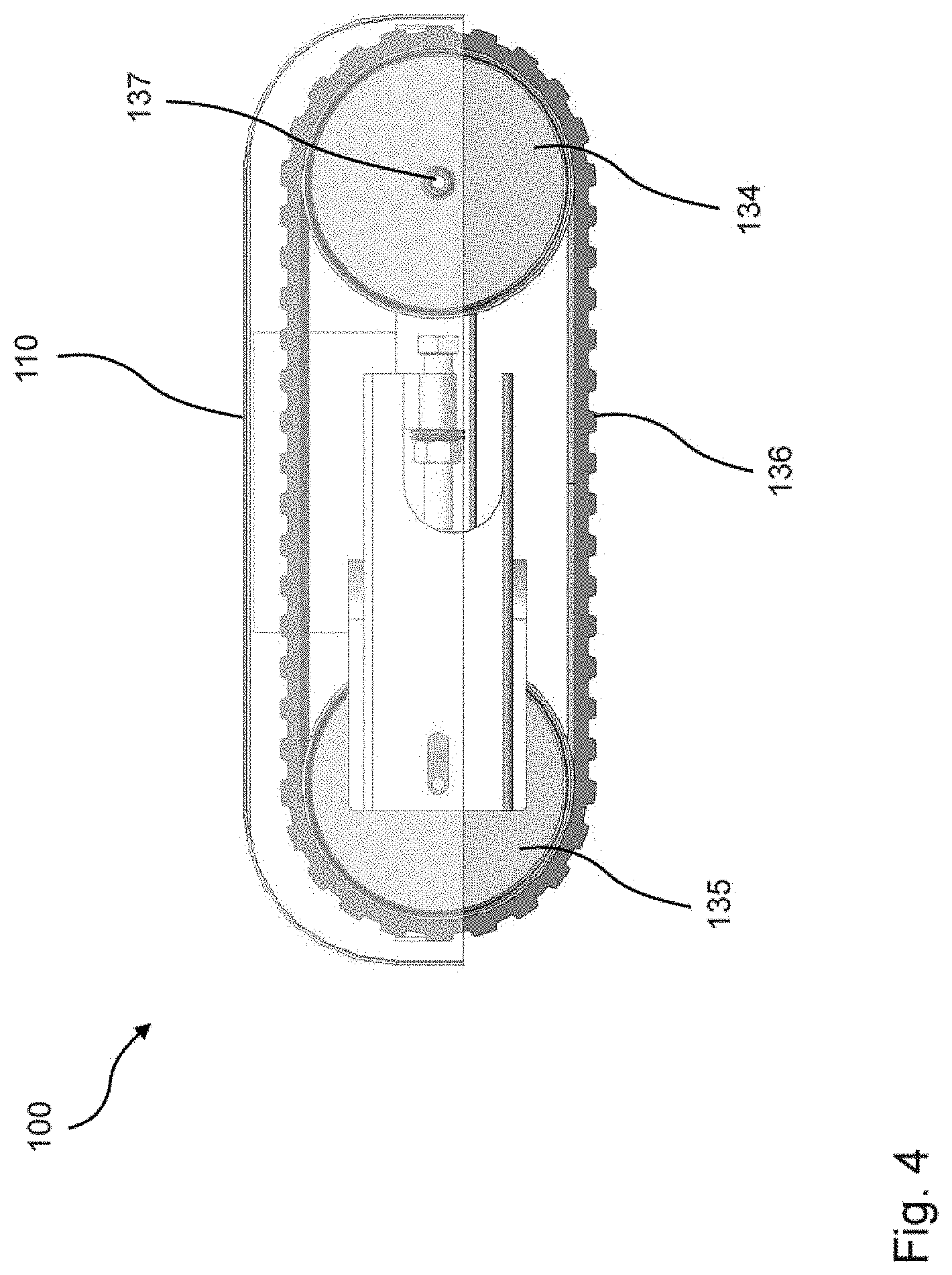
[0081] FIG. 4 is a schematic, two-dimensional side view of the animal-pen vehicle as per FIG. 1;
[0082] FIG. 5 is a schematic, three-dimensional view of the animal-pen vehicle from FIG. 1 with a functional unit;
[0083] FIG. 6 is a schematic side view of a further exemplary embodiment of an animal-pen vehicle;
[0084] FIG. 7 is a schematic side view of the animal-pen vehicle from FIG. 6 with a different functional unit;
[0085] FIG. 8 is a schematic plan views of three exemplary embodiments of animal-pen vehicle housings;
[0086] FIG. 9 is a schematic view of an animal pen with exemplary embodiments of a travel profile;
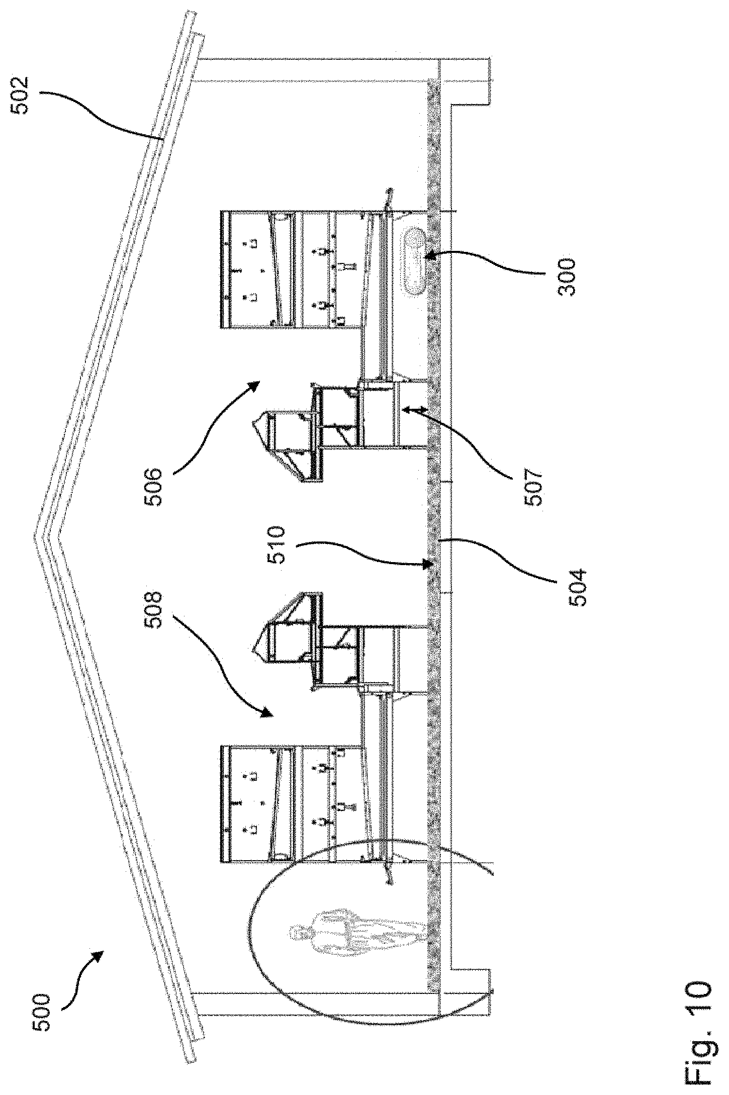
[0087] FIG. 10 is a schematic side view of an animal pen with an exemplary embodiment of an animal-pen vehicle;
[0088] FIG. 11 is a schematic illustration of the principle of a magnetic collision detection;
[0089] FIG. 12 is a schematic, three-dimensional view of an exemplary embodiment of a spring element;
[0090] FIG. 13 is a schematic, three-dimensional, partially sectional view of an exemplary embodiment of a housing with four spring elements; and
[0091] FIG. 14. is a schematic sectional illustration through a spring element fastened to a main body.
DETAILED DESCRIPTION OF THE EMBODIMENTS
[0092] In the Figures, identical or substantially functionally identical or similar elements are denoted by the same reference designations.
[0093] FIGS. 1 to 5 show an animal-pen vehicle 100 which has a housing 110 and a first crawler device 130 and a second crawler device 140. The housing 110 encloses the upper part of the animal-pen vehicle 100 such that the respective upper half of the first and second crawler device 130, 140 is enclosed to the outside by the housing 110. The housing 110 comprises a housing upper part 112, which has an areal and, during operation, substantially horizontal extent. Furthermore, the housing 110 comprises a first housing end part 114 and a second housing end part 116, which is arranged so as to be curved around the front and/or rear part of the animal-pen vehicle. Furthermore, the housing 110 has two housing side parts 118.
[0094] The internal construction of the animal-pen vehicle 100 can be seen, in particular, from FIG. 2. The Figure shows inter alia the first crawler device 130 which, aside from the crawler chain 136, also has a first drive axle 131. The drive axle 131 has a motor 132 and a coupling unit 133. With this coupling unit 133, the motor 132 is coupled via a first crawler wheel 134 to the crawler chain 136, such that the drive axle 131 is coupled via the first crawler wheel 134 to the crawler chain 136. The second crawler device 140 is of analogous construction and comprises a second drive axle 141. The crawler chain 136 may have any suitable material. In particular, it is preferable for the crawler chain 136 to be composed of a plastic and/or a steel or to comprise a plastic and/or a steel. It is particularly preferable for the crawler chain 136 to be formed from an elastomer, in particular, a rubber, or for the crawler chain to comprise an elastomer, in particular, a rubber.
[0095] Furthermore, the animal-pen vehicle 100 has a main body 120, on which the crawler devices 130, 140 are arranged laterally, wherein the motors of the drive axles 131, 141 project into the interior space of the main body 120 through passage openings 121, 122. Furthermore, an integrated positioning device and control device 150 and a battery box 115 with a battery 113 are arranged on the main body 120. Furthermore, a stroke-imparting unit 152 for the positioning device and control device 150 is arranged within the main body 120, wherein the positioning device and control device 150 can be removed from the animal-pen vehicle preferably with the stroke-imparting unit 152. In particular, FIGS. 3 and 4 show the specific construction of the crawler device 130, 140, wherein the arrangement over a first crawler wheel 134 and a second crawler wheel 135 is shown. These two crawler wheels 134, 135 serve for tensioning the crawler chain 136. The first crawler wheel 134 has an axle stub 137.
[0096] FIG. 5 shows a charging station 160 with a front wall 162 and with a first side wall 164 and a second side wall 166 arranged orthogonally with respect to the front wall 162 and likewise with a horizontal extent. On the front wall 162, there is furthermore arranged, at the bottom edge, a horizontal wall 168. The charging station 160 may be connected to the animal-pen vehicle 100 via a station coupling device 161 of the charging station 160 and a vehicle coupling device 170 of the animal-pen vehicle 100, and the battery of the animal-pen vehicle 100 can thus be charged. The station coupling device 161 has a coupling pin 163, which is arranged and designed to be arranged in a coupling opening 171 of the vehicle coupling device 170.
[0097] FIG. 6 shows an animal-pen vehicle 200 which has a crawler drive with a first crawler device 210 which comprises a first crawler wheel 214 and a second crawler wheel 215, which are looped around by a crawler chain 216. The animal-pen vehicle 200 furthermore has a pecking material container 202, which is connected via a conveying device 204 to a pecking dish 206. The pecking dish 206 offers a mobile conveyance of pecking material, such that poultry animals can firstly be supplied with feed by means of the animal-pen vehicle 200, which can furthermore also serve as manipulable material. The animal-pen vehicle 200 furthermore has various functional units. The functional unit may for example have, or be designed as, a bedding teller 220, a pushing device 230, and a sweeping unit 240. Furthermore, the animal-pen vehicle 200 has a chick paper dispensing device 270 for chick paper 271. Feed for chicks can be scattered on the chick paper 271 in order that the chicks do not have to stand on the cold animal pen floor while feeding. The chick paper 271 furthermore facilitates the cleaning of the animal pen.
[0098] In FIG. 7, the animal-pen vehicle 200 is equipped with an egg-collecting device 250, which comprises an articulated-arm robot 252 with an egg gripper 254. The animal-pen vehicle 200 furthermore has an egg-detecting device 256, which is preferably coupled to a control device of the articulated-arm robot 252 and of the gripper 254 such that a detected egg 10 can be picked up by the egg gripper 254 in targeted fashion.
[0099] FIG. 8 shows plan views of housings of animal-pen vehicles, which each have different geometries. The housing 301 has a circular geometry. The housing 302 comprises a rectangular portion and a semicircular portion. The housing 303 has a rectangular portion and a first semi-circular portion, the diameter of which has the same extent as the side of the rectangular portion on which the semicircular portion is arranged. At the apex of the abovementioned semicircular portion, there is a further portion comprising a rectangular portion and a circular-segment-shaped portion. The different housings 301, 302, 303 may be utilized for different usage purposes. The housing shape 302 has, in particular, the advantage that it can move forward as far as into a corner. The advantage of the housing 301 lies, in particular, in the low risk of injuries to poultry animals.
[0100] FIG. 9 shows an animal pen 400 with an outer animal-pen boundary 402 and two inner animal-pen boundaries 404, 406. The first inner animal-pen boundary 404 and the second inner animal-pen boundary 406 are designed as walls through which the poultry animals cannot pass. The first inner animal-pen boundary 404 and the second inner animal-pen boundary 406, however, have passage facilities through which an animal-pen vehicle can also move. Also arranged in a corner of the animal pen is the charging station 410, which is to be regarded as the base station for the animal-pen vehicle. Here, the batteries of the animal-pen vehicle can be charged and the animal-pen vehicle can be cleaned. Furthermore, the charging station 410 serves as a rest station for the animal-pen vehicle when it is not presently in operation. The charging station 410 may for example be designed analogously to the charging station 160 shown in FIG. 5.
[0101] Furthermore, FIG. 9 shows a travel profile of an animal-pen vehicle, which is illustrated by arrows and circles. The travel profile firstly comprises the movement pattern 412, which is distinguished by travel through the various animal pen areas. Furthermore, the travel profile also comprises the six preferential areas 420, 421, 422, 423, 424, 425, in which the animal-pen vehicle particularly preferentially moves. The preferential areas 420 to 425 are preferably selected on the basis of empirical values, in particular, on the basis of an accumulation of ground eggs and/or dwelling of poultry animals at nighttime having been detected here.
[0102] FIG. 10 shows an animal pen 500 with an animal-pen roof 502 and with a floor surface 504, wherein first animal-pen fixtures 506 and second animal-pen fixtures 508 are arranged on the floor surface 504. The animal-pen fixtures 506, 508 have a clear height 507 underneath them. The animal-pen vehicle 300 has an animal-pen vehicle height smaller than the clear height 507 of the animal-pen fixtures 506, 508.
[0103] By means of an animal-pen vehicle 100, 200, 300 described above, the positions at which poultry animals are residing, in particular, positions at which poultry animals are resting, can be influenced, in particular, for the purposes of reducing a ground egg quota and/or for the purposes of driving poultry animals. In particular, by travelling through a travel profile with a movement pattern 412 and at least one preferential area 420 to 425, the ground egg quota and instances of animals remaining on the floor surface overnight can be reduced.
[0104] FIG. 11 is a schematic illustration of the principle of a magnetic collision detection with a collision-detecting arrangement 600, which comprises a first collision-detecting device 601 and a second collision-detecting device 602. A non-optical detection in the form of a magnetic detection has the advantage of being particularly highly suitable for a dusty environment in the animal pen.
[0105] The two collision-detecting devices 601, 602 are of substantially identical form, but arranged so as to be offset with respect to one another by 90.degree.. In this way, different collision directions can be detected. Through the provision of two collision-detecting devices 601, 602, it is particularly preferably possible for an impact direction, in particular, a direction in which an object causing the collision or the impact is situated, for example in relation to a central and/or reference point of the animal-pen vehicle and/or in relation to an, in particular, instantaneous, direction of motion of the animal-pen vehicle, to be detected.
[0106] The first collision-detecting device 601 has a first magnetic impact sensor 611 and a first reference object 621. The second collision-detecting device 602 has a second magnetic impact sensor 612 and a second reference object 622.
[0107] The first impact sensor may preferably be arranged on the chassis of an animal-pen vehicle, and the first reference object arranged on a housing mounted in floating fashion on the chassis, in particular, on the housing bottom side. The first impact sensor may also be arranged on the housing, and the first reference object arranged on the chassis. The same arrangement principles also apply to the second collision-detecting device 602. It is also possible for different arrangements to be selected for the first and second collision-detecting device 601, 602.
[0108] The collision-detecting devices 601, 602 are arranged and designed to detect contact with an obstruction, in particular, with an object and/or an animal, preferably irrespective of the direction of motion of the animal-pen vehicle, that is to say, for example, also during reverse and/or sideward travel of the animal-pen vehicle.
[0109] The magnetic collision detection preferably takes the form of a continuous measurement, preferably with the possibility of storing multiple threshold values in the impact sensors 611, 612 and/or in a sensor controller. The reference objects 621, 622 are formed from magnetic material and comprise a magnetic pattern, in this case an alternating sequence of north and south poles in each case. A measurement of the relative movement of the first impact sensor and first reference object with respect to one another may be performed by counting the alternations in polarity. The profiles of the magnetic flux density B and of the electrical voltage U for the first collision-detecting device 601 that arise in the case of such a relative movement are plotted in the graphs 631 and 632. Correspondingly, a measurement of the relative movement of second impact sensor and second reference object with respect to one another may also be performed by counting the alternations in polarity, likewise resulting in corresponding profiles of the magnetic flux density B and of the electrical voltage U.
[0110] FIGS. 12 to 14 illustrate an exemplary embodiment of a spring element 700 and of the use thereof for a floating mounting of the housing 110 on the main body 120. The spring element 700 is of not solid but structured form, and has multiple regular recesses 701 in the form of hexagonal honeycombs, which are open at their top and bottom sides. A central honeycomb has a receptacle 702 for a fastening element in the form of a fastening pin 720.
[0111] The spring element 700 furthermore has a holding device 710 which has a cover part 713 and edge boundaries 711 with fastening flanges 712. Fastening holes 714 are provided on the fastening flanges 712.
[0112] The spring element 700 is of substantially disk-shaped form and, in the installed state, has an extent in a substantially horizontal plane which amounts to several times the height, which in the installed state is substantially vertical, of the spring element.
[0113] It is preferably possible, as illustrated in FIG. 13, for four mounting points with in each case one spring element 700 to be provided. FIG. 14 shows a fastening of the spring element to the main body 120 in the case of which the fastening pin 720 is fastened to the main body 120 and projects upward in the direction of the housing 110 and, in so doing, engages into the receptacle 702 of a honeycomb of the spring element 700.
[0114] A structured embodiment of disk-shaped spring elements has the advantage of a small structural height, high resistance to dirt and ammonia, and simple installation.
[0115] Collisions of the animal-pen vehicle with poultry animals and/or objects can be detected by means of the collision-detecting arrangement 600. It is thereby possible, on the basis of a collision, to provide appropriate control, for example, to stop the animal-pen vehicle.
* * * * *
D00000
D00001
D00002
D00003
D00004
D00005
D00006
D00007
D00008
D00009
D00010
D00011
D00012

D00013

D00014

XML
uspto.report is an independent third-party trademark research tool that is not affiliated, endorsed, or sponsored by the United States Patent and Trademark Office (USPTO) or any other governmental organization. The information provided by uspto.report is based on publicly available data at the time of writing and is intended for informational purposes only.
While we strive to provide accurate and up-to-date information, we do not guarantee the accuracy, completeness, reliability, or suitability of the information displayed on this site. The use of this site is at your own risk. Any reliance you place on such information is therefore strictly at your own risk.
All official trademark data, including owner information, should be verified by visiting the official USPTO website at www.uspto.gov. This site is not intended to replace professional legal advice and should not be used as a substitute for consulting with a legal professional who is knowledgeable about trademark law.