Secure Pairing Of Devices Via Pairing Facilitator-intermediary Device
Panther; Heiko Gernot Albert
U.S. patent application number 16/743918 was filed with the patent office on 2020-07-16 for secure pairing of devices via pairing facilitator-intermediary device. The applicant listed for this patent is Fitbit, Inc.. Invention is credited to Heiko Gernot Albert Panther.
| Application Number | 20200229250 16/743918 |
| Document ID | 20200229250 / US20200229250 |
| Family ID | 53401387 |
| Filed Date | 2020-07-16 |
| Patent Application | download [pdf] |


View All Diagrams
| United States Patent Application | 20200229250 |
| Kind Code | A1 |
| Panther; Heiko Gernot Albert | July 16, 2020 |
SECURE PAIRING OF DEVICES VIA PAIRING FACILITATOR-INTERMEDIARY DEVICE
Abstract
The present inventions, in one aspect, are directed to systems and circuitry for and/or methods of establishing communication having one or more pairing facilitator-intermediary devices (for example, a network connected server) to enable or facilitate pairing and/or registering at least two devices (e.g., (i) a portable biometric monitoring device and (ii) a smartphone, laptop and/or tablet) to, for example, recognize, interact and/or enable interoperability between such devices. The pairing facilitator-intermediary device may responsively communicates information to one or more of the devices (to be paired or registered) which, in response, enable or facilitate such devices to pair or register. The present inventions may be advantageous where one or both of the devices to be paired or registered is/are not configured (e.g., include a user interface or certain communication circuitry that is configured or includes functionality) to pair devices without use of a facilitator-intermediary device.
| Inventors: | Panther; Heiko Gernot Albert; (Oakland, CA) | ||||||||||
| Applicant: |
|
||||||||||
|---|---|---|---|---|---|---|---|---|---|---|---|
| Family ID: | 53401387 | ||||||||||
| Appl. No.: | 16/743918 | ||||||||||
| Filed: | January 15, 2020 |
Related U.S. Patent Documents
| Application Number | Filing Date | Patent Number | ||
|---|---|---|---|---|
| 16254410 | Jan 22, 2019 | 10575352 | ||
| 16743918 | ||||
| 15682494 | Aug 21, 2017 | 10187918 | ||
| 16254410 | ||||
| 15012552 | Feb 1, 2016 | 9743443 | ||
| 15682494 | ||||
| 14642352 | Mar 9, 2015 | 9253168 | ||
| 15012552 | ||||
| 13872015 | Apr 26, 2013 | |||
| 14642352 | ||||
| 61638650 | Apr 26, 2012 | |||
| Current U.S. Class: | 1/1 |
| Current CPC Class: | H04W 12/00 20130101; H04L 63/0471 20130101; H04W 12/003 20190101; H04L 63/0281 20130101; H04W 76/14 20180201; A61B 5/11 20130101; A61B 5/6824 20130101; A61B 5/681 20130101; H04W 12/0023 20190101; A61B 5/0205 20130101; A61B 5/6829 20130101; H04W 12/02 20130101; H04L 63/0464 20130101; A61B 5/0024 20130101 |
| International Class: | H04W 76/14 20060101 H04W076/14; H04L 29/06 20060101 H04L029/06; H04W 12/00 20060101 H04W012/00; H04W 12/02 20060101 H04W012/02; A61B 5/00 20060101 A61B005/00 |
Claims
1. A method for pairing a portable monitoring device with a computing device, the method comprising: the first computing device: sending, to a server, an instruction to facilitate pairing of the portable monitoring device with the first computing device; receiving, from the server, first pairing information including an identifier of a second computing device previously paired with the portable monitoring device; receiving, from the server, first pairing information including an identifier of a second computing device previously paired with the portable monitoring device; sending the first pairing information, including the identifier, from the first computing device to the portable monitoring device; receiving second pairing information from the portable monitoring device, the second pairing information being obtained by the portable monitoring device from the server via the second computing device using the identifier; and pairing the first computing device with the portable monitoring device based on the first pairing information and the second pairing information, wherein pairing the first computing device with the portable monitoring device comprises creating a communication link between the first computing device and the portable monitoring device.
2. The method of claim 1, wherein: the pairing is configured to facilitate a transfer of activity data from the portable monitoring device to the first computing device, the method further comprises receiving by the first computing device the activity data from the portable monitoring device via the link, and the activity data is representative of a physiological metric collected by one or more sensors embedded in the portable monitoring device.
3. The method of claim 2, further comprising: providing access to a user account on a display device of the first computing device via a web service; and displaying the activity data on the display device.
4. The method of claim 2, further comprising: receiving by the first computing device the activity data from the portable monitoring device via the communication link.
5. The method of claim 2, wherein the activity data is representative of a physiological metric collected by one or more sensors embedded in the portable monitoring device.
6. The method of claim 1, wherein the first pairing information further includes an identifier of the portable monitoring device and a first secret code.
7. The method of claim 6, wherein: the second pairing information includes an identifier of the second computing device and a second secret code.
8. The method of claim 1, wherein the portable monitoring device does not transmit data directly to the server.
9. The method of claim 1, wherein the receiving by the first computing device of the first pairing information and the sending of the first pairing information from the first computing device to the portable monitoring device are performed automatically.
10. The method of claim 1, wherein: the portable monitoring device comprises a biometric device and the first computing device comprises at least one of: a smart phone, a tablet, and computer, wherein the biometric device includes a display unit to display information, and the biometric device is configured to be worn by a user.
11. The method of claim 1, further comprising: the portable monitoring device communicating bi-directionally with the server via a computer network to send data to the server and to receive the second pairing information from the server.
12. The method of claim 1, wherein: the portable monitoring device lacks a user interface for receiving a pairing selection, and the portable monitoring device has a dead front display.
13. A first computing device comprising: a user interface configured to receive a selection of a portable monitoring device for pairing with the first computing device; a communication unit configured to: send via a computer network to a server an instruction to facilitate pairing the portable monitoring device with the first computing device, receive, via the computer network from the server, first pairing information including an identifier of a second computing device previously paired with the portable monitoring device, send the first pairing information to the portable monitoring device, receive second pairing information from the portable monitoring device, the second pairing information being obtained by the portable monitoring device from the server via the second computing device using the identifier; and a processor configured to pair the first computing device with the portable monitoring device based on the first pairing information and the second pairing information, wherein pairing the first computing device with the portable monitoring device comprises creating a communication link between the first computing device and the portable monitoring device.
14. The first computing device of claim 13, wherein: the communication unit configured to receive activity data from the portable monitoring device via the link, and the activity data is representative of a physiological metric collected by one or more sensors embedded in the portable monitoring device.
15. The first computer device of claim 13, wherein: the first pairing information further includes an identifier of the portable monitoring device and a first secret code, and the second pairing information includes an identifier of the second computing device and a second secret code.
16. The first computing device of claim 13, wherein the portable monitoring device does not transmit data directly to the server.
17. The first computing device of claim 13, wherein the communication unit is further configured to receive the first pairing information from the server and send the first pairing information the portable monitoring device automatically.
18. The first computing device of claim 13, wherein: the user interface is configured to provide access to a user account via a web service, and the user interface includes a display device configured to display the activity data.
19. The first computing device of claim 13, wherein: the portable monitoring device comprises a biometric device and the first computing device comprises at least one of: a smart phone or a tablet or a computer, the biometric device includes a display unit to display information, and the biometric device is configured to be worn by a user.
20. The first computing device of claim 13, wherein the portable monitoring device is configured to communicate bi-directionally with the server via the computer network to send data to the server and to receive the second pairing information from the server.
21. The first computing device of claim 13, wherein: the portable monitoring device lacks a user interface for receiving a selection, and the portable monitoring device has a dead front display.
22. A non-transitory computer readable storage medium having instructions stored thereon that, when executed cause a processor of a first computing device to: send, to a server, an instruction to facilitate pairing of a portable monitoring device with the first computing device; receive, from the server, first pairing information including an identifier of a second computing device previously paired with the portable monitoring device; send the first pairing information, including the identifier, from the first computing device to the portable monitoring device; receive second pairing information from the portable monitoring device, the second pairing information being obtained by the portable monitoring device from the server via the second computing device using the identifier; and pair the first computing device with the portable monitoring device based on the first pairing information and the second pairing information, the pairing performed to begin a transfer of activity data from the portable monitoring device to the first computing device, wherein pairing the first computing device with the portable monitoring device comprises creating a link between the first computing device and the portable monitoring device.
23. The non-transitory computer readable storage medium of claim 22, wherein the first pairing information includes an identifier of the portable monitoring device and a secret code.
Description
CLAIM OF PRIORITY
[0001] An Application Data Sheet is filed concurrently with this specification as part of the present application. Each application that the present application claims benefit of or priority to as identified in the concurrently filed Application Data Sheet is incorporated by reference herein in its entirety and for all purposes.
INTRODUCTION
[0002] In one aspect, the present inventions relate to systems and circuitry for and/or methods of establishing communication having one or more pairing facilitator-intermediary devices (for example, a network connected server) to enable or facilitate pairing and/or registering two or more devices (for example, (i) a portable biometric monitoring device and (ii) a smartphone, laptop and/or tablet) to, for example, recognize, interact and/or identify such devices and/or enable interoperability between such devices. In one embodiment, the pairing facilitator-intermediary device responsively communicates data and/or instructions to one or more of the devices (to be paired or registered) which, in response, enable or facilitate such devices to pair or register. The present inventions may be advantageous where one or both of the devices to be paired or registered do not include or employ functionality and/or resident circuitry (for example, an interface (for example, a user interface) or resident communication circuitry) that allows, enables or permits a user to pair and/or register the devices. For example, where the device to be paired or registered do not possess a, or employ its user interface and/or communication circuitry which is suitable for selection, entering and/or communicating data to its counterpart device (for example, via communicating out-of-band data).
[0003] Notably, pairing or registering devices may be characterized as enabling interoperability between such devices and/or an initialization process which creates a link (for example, a lasting and/or sustainable link) between two or more devices to facilitate, allow and/or make possible future communication between the devices. After the pairing process is complete, one or more of the devices involved in the pairing process may save information about one or more of the other devices so that when a new, subsequent and/or future communication link is to be set-up, little or no user interaction is required to create the connection. Similarly, registering devices with each other or with a third device allows subsequent and/or future communication between two or more of the devices to occur with little or no user interaction.
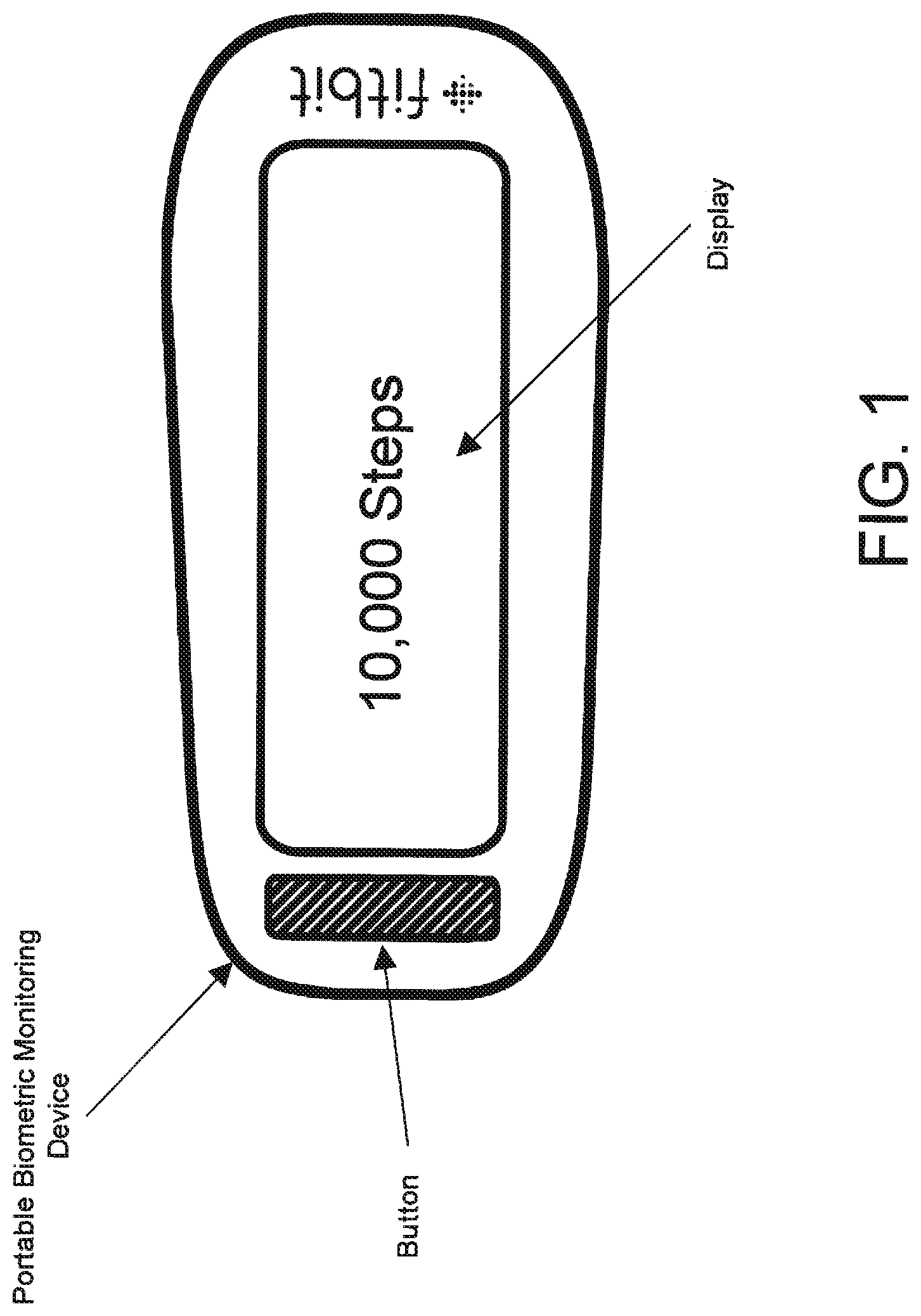
[0004] In one embodiment, one or more of the devices to be paired or registered is/are portable biometric monitoring device(s). Such portable biometric monitoring device(s) may, according to embodiments described herein, have shapes and/or sizes that are/is adapted for coupling to (for example, secured to, worn, carried or borne by, etc.) the body or clothing of a user and, when worn, do not impede motion, activity or the like of the user. Examples of portable biometric monitoring devices are shown in FIGS. 1-5. Some portable biometric monitoring devices such as those in FIGS. 1-2 may have a display and a button. Other portable biometric monitoring devices may have more limited user interfaces such as those shown in FIGS. 4A, 4B and 5. Indeed, some portable biometric monitoring devices may have little or no user interface features such as displays, indicators, or buttons. In one embodiment, the devices collect one or more types of physiological and/or environmental data from embedded sensors and/or external devices and communicate or relay such information to other devices, including devices capable of serving as an Internet-accessible data sources, thus permitting the collected data to be viewed, for example, using a web browser or network-based application. For example, while the user is wearing a biometric monitoring device, the device may calculate and store the user's step count using one or more sensors. The device then transmits data representative of the user's step count to an account on a web service (for example, www.fitbit.com), computer, mobile phone, or health station where the data may be stored, processed, and visualized by the user. Indeed, the device may measure or calculate a plurality of other physiological metrics in addition to, or in place of, the user's step count.
[0005] Notably, other physiological metrics include, but are not limited to, energy expenditure (for example, calorie burn), floors climbed and/or descended, heart rate, heart rate variability, heart rate recovery, location and/or heading (for example, through GPS), elevation, ambulatory speed and/or distance traveled, swimming lap count, bicycle distance and/or speed, blood pressure, blood glucose, skin conduction, skin and/or body temperature, electromyography, electroencephalography, weight, body fat, caloric intake, nutritional intake from food, medication intake, sleep periods (i.e., clock time), sleep phases, sleep quality and/or duration, pH levels, hydration levels, and respiration rate. The device may also measure or calculate metrics related to the environment around the user such as barometric pressure, weather conditions (for example, temperature, humidity, pollen count, air quality, rain/snow conditions, wind speed), light exposure (for example, ambient light, UV light exposure, time and/or duration spent in darkness), noise exposure, radiation exposure, and magnetic field.
[0006] Furthermore, the device or the system collating the data streams may calculate metrics derived from this data. For example, the device or system may calculate the user's stress and/or relaxation levels through a combination of heart rate variability, skin conduction, noise pollution, and sleep quality. In another example, the device or system may determine the efficacy of a medical intervention (for example, medication) through the combination of medication intake, sleep and/or activity data. In yet another example, the device or system may determine the efficacy of an allergy medication through the combination of pollen data, medication intake, sleep and/or activity data. These examples are provided for illustration only and are not intended to be limiting or exhaustive. Further embodiments and implementations of sensor devices are described and/or illustrated in U.S. patent application Ser. No. 13/156,304, entitled "Portable Biometric Monitoring Devices and Methods of Operating Same" filed Jun. 8, 2011, which is incorporated herein, in its entirety, by reference.
BRIEF DESCRIPTION OF THE DRAWINGS
[0007] In the course of the detailed description to follow, reference will be made to the attached drawings. These drawings show different aspects of the present inventions and, where appropriate, reference numerals illustrating like structures, components, materials and/or elements in different figures are labeled similarly. The various embodiments disclosed herein are illustrated by way of example, and not by way of limitation, in the figures of the accompanying drawings and in which like reference numerals refer to the same and/or similar structures/components/features/elements. It is understood that various combinations of the structures, components, features and/or elements, other than those specifically shown, are contemplated and are within the scope of the present inventions.
[0008] Moreover, there are many inventions described and illustrated herein. The present inventions are neither limited to any single aspect nor embodiment thereof, nor to any combinations and/or permutations of such aspects and/or embodiments. Moreover, each of the aspects of the present inventions, and/or embodiments thereof, may be employed alone or in combination with one or more of the other aspects of the present inventions and/or embodiments thereof. For the sake of brevity, certain permutations and combinations are not discussed and/or illustrated separately herein.
[0009] The various embodiments disclosed herein are illustrated by way of example, and not by way of limitation, in the figures of the accompanying drawings and in which like reference numerals refer to similar elements and in which:
[0010] FIG. 1 illustrates an example of a portable monitoring device.
[0011] FIG. 2 illustrates an example of a portable monitoring device having a button and a dead front display.
[0012] FIG. 3 illustrates a user extremity mounted portable monitoring device having a button, display, and a band.
[0013] FIG. 4A illustrates a portable monitoring device having multiple LED's to display information to the user.
[0014] FIG. 4B illustrates a portable monitoring device having multiple LED's to display information to the user.
[0015] FIG. 5 illustrates a band case for a portable biometric monitoring device and a portable biometric monitoring device having multiple LED's to display information to the user.
[0016] FIG. 6 is a block diagram of an embodiment of a system in which a first device and a second device directly communicate with each other as well as communicate with a pairing facilitator-intermediary device to enable and implement a pairing or registering process.
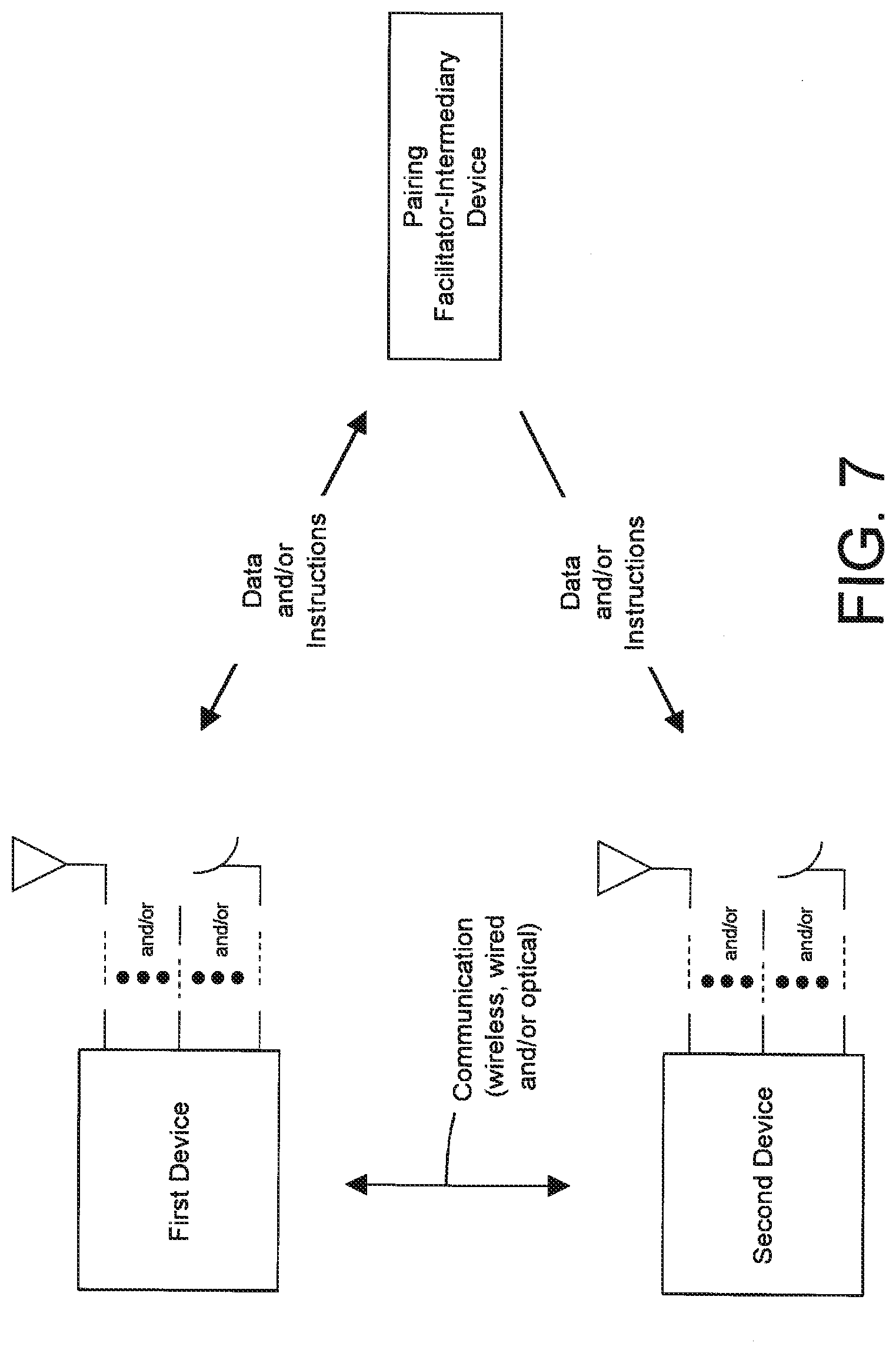
[0017] FIG. 7 is a block diagram of an embodiment of a system in which the first device bi-directionally communicates with the pairing facilitator-intermediary device and the second device receives data and/or instructions from the pairing facilitator-intermediary device, and the first and second devices communicate with each other to implement the pairing or registering process.
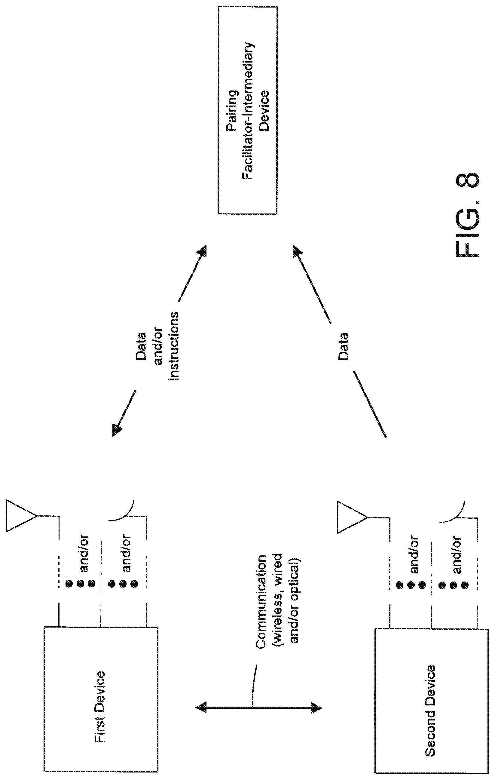
[0018] FIG. 8 is a block diagram of an embodiment of a system in which the first device communicates with the pairing facilitator-intermediary device and the second device sends data to the pairing facilitator-intermediary device, and the first and second devices communicate to implement the pairing or registering process.
[0019] FIG. 9 is a block diagram of an embodiment of a system in which the first device communicates with the pairing facilitator-intermediary device and the first and second devices communicate to implement the pairing or registering process.
[0020] FIG. 10 illustrates, in block diagram form, an embodiment having a first device, second device, third device and facilitator-intermediary device wherein the interaction between the first device and second device with each other and with a pairing facilitator-intermediary device occurs to facilitate pairing or registering processes.
[0021] FIG. 11 illustrates, in block diagram form, an embodiment having a first device, second device, third device and facilitator-intermediary device wherein the interaction between the first device and second device with each other and with a pairing facilitator-intermediary device occurs to facilitate pairing or registering processes.
[0022] FIG. 12 illustrates, in block diagram form, an embodiment having a first device, second device, third device and facilitator-intermediary device wherein the interaction between the first device and second device with each other and with a pairing facilitator-intermediary device occurs to facilitate pairing or registering processes.
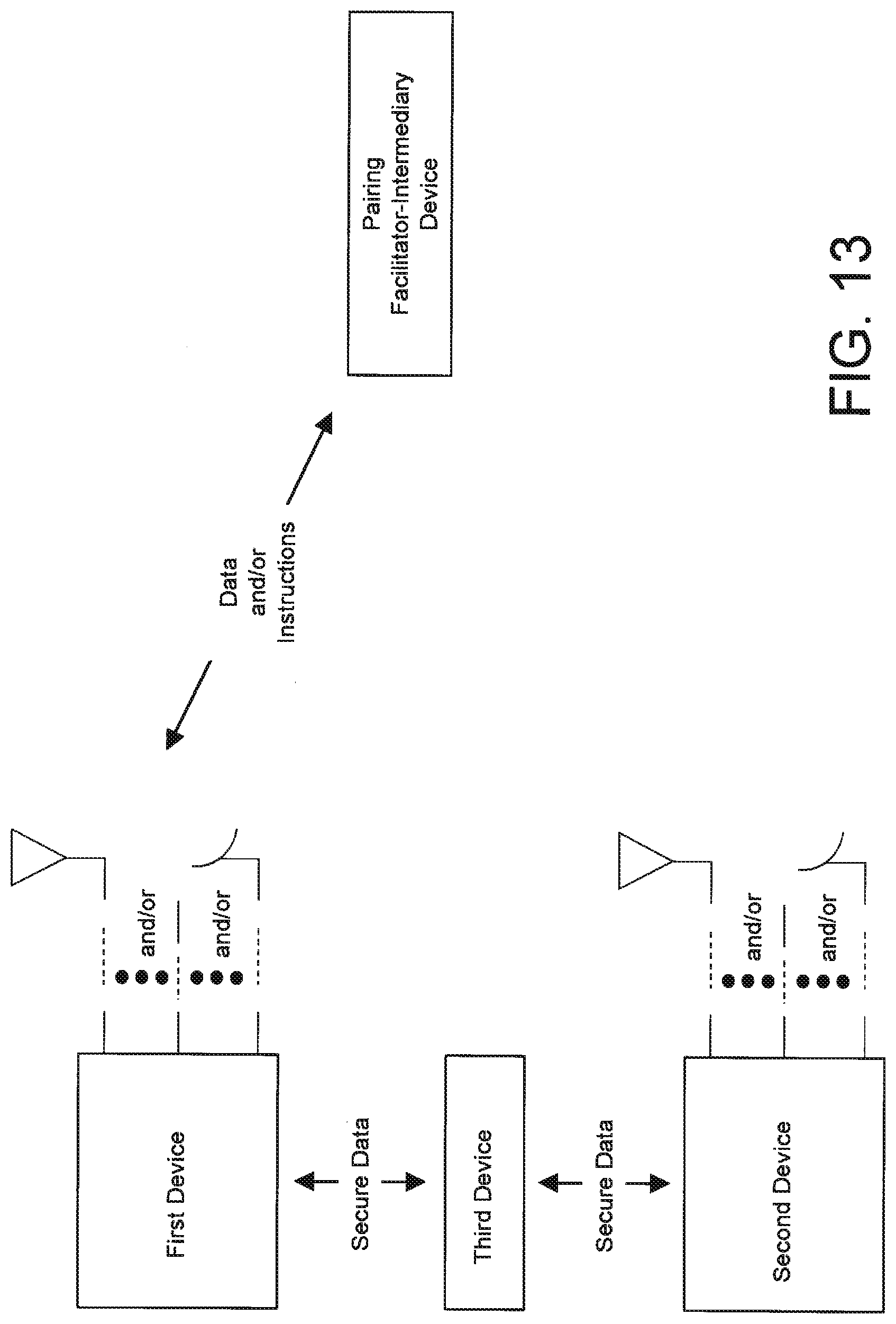
[0023] FIG. 13 illustrates, in block diagram form, an embodiment having a first device, second device, third device and facilitator-intermediary device wherein the interaction between the first device and second device with each other and with a pairing facilitator-intermediary device occurs to facilitate pairing or registering processes.
[0024] FIG. 14 is a block diagram of an embodiment having a first device, second device and facilitator-intermediary device wherein the interaction between the first device and second device with a pairing facilitator-intermediary device facilitates pairing or registering processes.
[0025] FIG. 15A illustrates, in block diagram form, a first and/or second device(s) to be paired, notably, the device may communicate using any technique, protocols and/or circuitry now known or later developed including wireless, wired and optical techniques.
[0026] FIG. 15B illustrates, in block diagram form, a first and/or second device(s) having a device to be paired and an interface device.
[0027] FIG. 15C illustrates, in block diagram form, first and second devices, according to embodiments of the present inventions, second device uses circuitry in the first device to communicate with the pairing facilitator-intermediary device.
[0028] FIG. 16 illustrates, in block diagram form, an embodiment where a first device is already paired to a second device, but is to be paired to a third device.
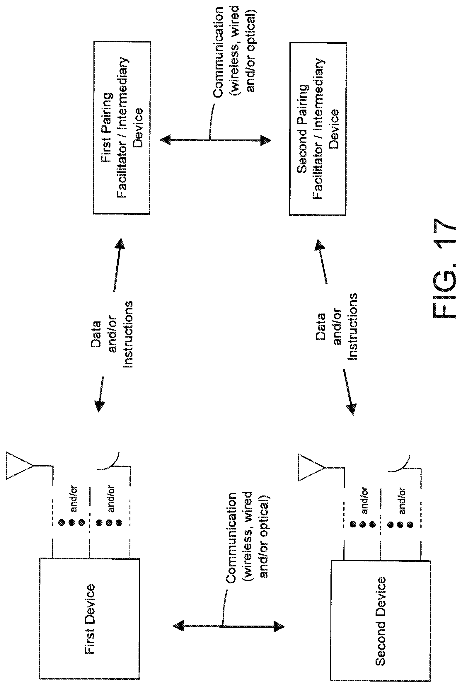
[0029] FIG. 17 illustrates an embodiment where multiple pairing facilitator-intermediary devices in communication with each other may send and/or receive data and/or instructions with a first and/or second device.
DETAILED DESCRIPTION
[0030] FIG. 1 illustrates an example of a portable biometric or activity sensor or monitoring device (hereinafter collectively "portable biometric monitoring device") having a button and a display and including a housing having a physical size and shape that is adapted to couple to the body of the user.
[0031] FIG. 2 illustrates an example of a portable biometric monitoring device having a button and a dead front display; notably, in the dead front display, the display is obscured from view when the display is off typically by placing a semi-transparent material in front of the display.
[0032] FIG. 3 illustrates a user extremity (for example, wrist or ankle) mounted portable biometric monitoring device having a button, display, and a band (having protrusions and notches/apertures) to secure the portable biometric monitoring device to the wrist or ankle of a user; notably, any mechanism or technique now known or later developed may be employed to physically couple the portable biometric monitoring device to the user.
[0033] FIGS. 4A and 4B illustrates a portable biometric monitoring device having multiple LED's to display information to the user; notably, any mechanism or technique now known or later developed may be employed to physically couple or "attach" the portable biometric monitoring device to the user; for example, the sensor case of FIG. 5 may be employed or the portable biometric monitoring device attached to a band (like, for example, an arm or wrist/watch band); indeed, the portable biometric monitoring device need not include any attachment mechanism and may, for example, be physically coupled or "attached" to the user via being disposed in a pocket of clothing, a sock and/or shoe/sneaker of the user.
[0034] In one embodiment, an activity monitoring device, as shown in FIG. 4B has a housing defined by a molded structure that is elongated along a dimension that extends between a first end and a second end of the molded structure. The molded structure has an interior space. The activity monitoring device further has a circuit board dimensioned to fit within the interior space. The circuit board has a sensor, an electronics unit, and a memory. The memory is used for storing activity data and the circuit board further has an antenna and at least one light emitting diode. The activity monitoring device has a cap that connects to the second end of the molded structure to enclose the circuit board within the interior space. The activity monitoring device has a communication contact disposed at a surface of the first end of the molded structure. The communication contact provides a contact to charge a battery that is coupled to the circuit board.
[0035] In an embodiment, light emitted from the at least one light emitting diode, when active, is viewable from an exterior surface of the molded structure.
[0036] In one embodiment, the antenna communicates via radio frequency waves with a computing device to facilitate communication of the activity data or receive instructions from the computing device.
[0037] In one embodiment, the molded structure has an opening at the second end to allow entry from and exit of the circuit board with respect to the interior space.
[0038] In an embodiment, the interior space is bounded by walls of the molded structure and the opening. The first end includes one of the walls.
[0039] In one embodiment, the second end encompasses an opening to allow passage of the circuit board into and out of the opening.
[0040] In an embodiment, the cap includes a lip portion that fits within the housing.
[0041] In one embodiment, activity data includes an environmental metric or a physiological metric.
[0042] In an embodiment, the activity monitoring device includes a transmitter and receiver unit associated with the circuit board and coupled to the antenna to enable communication of the activity data.
[0043] In one embodiment, the activity monitoring device includes a transmitter and receiver unit. The electronics unit sends the activity data via the transmitter unit and the antenna to a computing device.
[0044] In an embodiment, the computing device includes a portable electronic device.
[0045] In one embodiment, the cap detaches from the second end of the molded structure to allow removal of the circuit board from the interior space.
[0046] In one embodiment, the molded structure has a substantially tubular shape.
[0047] In an embodiment, the substantially tubular shape has rounded edges and substantially straight walls.
[0048] In one embodiment, the electronics unit is configured to receive the activity data from the sensor for storage in the memory or for transferring to a computing device via the antenna.
[0049] In an embodiment, a method includes generating activity data when a user is performing an activity. The activity data is detected by a sensor of a monitoring device worn by a user. The method further includes accessing the activity data from a memory device of the monitoring device. The memory device is located in an interior space of a housing of the monitoring device. The method includes communicating the activity data from an electronic device located inside the housing via a transmitter and an antenna to a computing device located outside the housing. The antenna and the transmitter are located inside the housing. The housing is enclosed by a cap and includes a battery that is charged via a communication contact. The communication contact is located at a first end of the housing and the antenna located at a second end of the housing.
[0050] In an embodiment, the method includes sending pairing information associated with the monitoring device via a computing device to a server. The method includes pairing of the monitoring device with the computing device after the pairing information is received by the computing device from the server.
[0051] In one embodiment, the method includes sending the activity data via a computing device to a server.
[0052] In an embodiment, the activity includes swimming, bicycling, or sleeping.
[0053] FIG. 5 illustrates a band case for a portable biometric monitoring device and a portable biometric monitoring device having multiple LED's to display information to the user, wherein this illustrative example, a sensor case (in which the portable biometric monitoring device may be disposed during operation) is physically coupled to the user via straps/bands having protrusions or posts (or the like) on the first strap/band to engage notches or apertures on the second strap/band to secure the sensor case to the user (for example, to a wrist, arm or leg); notably, any mechanism or technique now known or later developed may be employed to physically couple the sensor case and/or portable biometric monitoring device to the user--for example, the sensor case may be attached to a band (like, for example, an arm or wrist/watch band); indeed, the sensor case and/or portable biometric monitoring device need not include any attachment mechanism and may, for example, be physically coupled or "attached" to the user via being disposed in a pocket of clothing, a sock and/or shoe/sneaker of the user.
[0054] In an embodiment, a wearable band includes a strap having a protrusion located along a portion of a length of the strap. The strap has notches located along another portion of the length of the strap. The protrusion engages with a selected one of the notches. The wearable band includes a cavity for holding an activity monitoring device. The activity monitoring device includes a housing defined by a molded structure that is elongated along a dimension that extends between a first end and a second end of the molded structure. The molded structure has an interior space. The activity monitoring device further includes a circuit board dimensioned to fit within the interior space. The circuit board has a sensor, an electronics unit, and a memory. The memory stores activity data. The circuit board has an antenna and at least one light emitting diode. The activity monitoring device has a cap that connects to the second end of the molded structure to enclose the circuit board within the interior space. The activity monitoring device includes a communication contact disposed at a surface of the first end of the molded structure. The communication contact provides a contact to charge a battery that is coupled to the circuit board.
[0055] In one embodiment, the strap has a width and a depth and the length is greater than the width and the width is greater than the depth.
[0056] In an embodiment, the protrusion extends into and fit with one of the notches.
[0057] In an embodiment, one of the notches includes an aperture for surrounding the protrusion when engaged with the protrusion.
[0058] In an embodiment, the activity monitoring device includes at one light emitter. Light emitted from the at least one light emitter, when active, is viewable from an exterior surface of the molded structure.
[0059] In one embodiment, a method includes generating activity data when a user is performing an activity. The activity data is detected by a sensor of a monitoring device that fits within a pouch of a strap. The strap has a protrusion located along a portion of a length of the strap. The strap has notches located along another portion of the length of the strap. The protrusion engages with a selected one of the notches. The method further includes accessing the activity data from a memory device of the monitoring device. The memory device is located in an interior space of a housing of the monitoring device. The method includes communicating the activity data from an electronic device located inside the housing via an antenna to a computing device located outside the housing. The antenna is located inside the housing, which is enclosed by a cap. The housing includes a battery for being charged via a communication contact, which is located at a first end of the housing. The antenna is located at a second end of the housing.
[0060] In an embodiment, the method includes sending pairing information associated with the monitoring device via a computing device to a server. The method further includes pairing with the computing device after the pairing information is received by the computing device from the server.
[0061] FIGS. 6-9 illustrate, in block diagram form, embodiments having a first device (for example, a portable biometric monitoring device), second device (for example, a smartphone) and facilitator-intermediary device (for example, a server) wherein interaction between the first device and second device with a pairing facilitator-intermediary device facilitate pairing or registering processes, according to embodiments of the present inventions; in one embodiment, the first and second device directly communicate with each other as well as communicate (for example, send and/or receive data and/or instructions) with the pairing facilitator-intermediary device to enable and/or implement the pairing or registering process (see, for example, FIG. 6); in another embodiment, the first device bi-directionally communicates (for example, sends and/or receives data and/or instructions) with the pairing facilitator-intermediary device, the second device receives data and/or instructions from the pairing facilitator-intermediary device, and the first and second devices communicate to implement the pairing or registering process (see, for example, FIG. 7); in another embodiment, the first device communicates (for example, sends and/or receives data and/or instructions) with the pairing facilitator-intermediary device and the second device sends data to the pairing facilitator-intermediary device, wherein the first and second devices communicate to implement the pairing or registering process (see, for example, FIG. 8); in yet another embodiment, the first device communicates (for example, sends and/or receives data and/or instructions with the pairing facilitator-intermediary device) and the first and second devices communicate to implement the pairing or registering process (see, for example, FIG. 9); notably, the first and second devices may communicate using any technique, protocols and/or circuitry now known or later developed including wireless, wired and optical techniques; moreover, it should be noted that the communication channel between first and second device may be unsecure before pairing is complete whereas the communication channel between the first device and the pairing facilitator-intermediary device (and, in certain embodiments, to the secondary device as well) and/or the communication channel between the second device and the pairing facilitator-intermediary device (and, in certain embodiments, to the first device as well) are trusted or secure communication channel(s) after the first and second device have been paired to the pairing facilitator-intermediary device (see, for example, FIGS. 6-14,16 and 17).
[0062] FIGS. 10-13 illustrate, in block diagram form, embodiments having a first device, second device, third device and facilitator-intermediary device wherein the interaction between the first device and second device with each other and with a pairing facilitator-intermediary device to facilitate pairing or registering processes, according to embodiments of the present inventions; in one embodiment, the first and second device may communicate directly with facilitator-intermediary device and exchange secure data and/or instructions through a third device to enable and/or implement the pairing or registering process; the notably, the embodiment of exchanging secure data and/or instructions through a third device to enable and/or implement the pairing or registering process may be implemented in any of the embodiments hereof, including those of FIGS. 6-9.
[0063] FIG. 14 illustrates, in block diagram form, an embodiment having a first device, second device and facilitator-intermediary device wherein the interaction between the first device and second device with a pairing facilitator-intermediary device facilitate pairing or registering processes, according to embodiments of the present inventions, wherein first and second device send and/or receive data, instructions, and/or secure data with the pairing facilitator-intermediary device through one or multiple communication channels.
[0064] FIG. 15A illustrates, in block diagram form, a first and/or second device(s) to be paired (for example, a portable biometric monitoring device, laptop, smartphone, desktop computer or server); notably, the device may communicate (for example, data and/or instructions) using any technique, protocols and/or circuitry now known or later developed including wireless, wired and optical techniques.
[0065] FIG. 15B illustrates, in block diagram form, a first and/or second device(s) having a device to be paired and an interface device, according to embodiments of the present inventions, wherein the device of FIG. 15B may be implemented in any of the embodiments described and/or illustrated herein, wherein the device to be paired (for example, a portable biometric monitoring device) and/or interface device (for example, a laptop, tablet computer, or smartphone) may send and/or receive data, for example, wirelessly; notably, the device to be paired and/or interface device may communicate with each other through one or multiple techniques, protocols and/or circuitry now known or later developed, including but not limited to wired, wireless, or optical communication.
[0066] FIG. 15C illustrates, in block diagram form, first and second devices (i.e., the devices to be paired), according to embodiments of the present inventions, second device uses circuitry in the first device to communicate (for example, send and/or receive data and/or instructions with the pairing facilitator-intermediary device) and, using the data and/or instructions, the first and second devices subsequently communicate to implement the pairing or registering process; notably, the first and second devices may communicate using any technique, protocols and/or circuitry now known or later developed including wireless, wired and optical techniques; moreover, it should be noted that the second device may communicate through a secure communication channel to the pairing facilitator-intermediary device using communication circuitry on the first device to transfer communication from the second device to the pairing facilitator-intermediary device and/or transfer communication from the pairing facilitator-intermediary device to the second device before and/or after pairing using techniques such as encryption, obfuscation, or any other method which makes it impossible or difficult for the first device to intercept, interpret, and/or modify data or instructions sent from the second device to the pairing facilitator-intermediary device and/or data or instructions sent from the pairing facilitator-intermediary device to the second device.
[0067] FIG. 16 illustrates, in block diagram form, an embodiment where a first device is already paired to a second device, but is to be paired to a third device, accordingly to an embodiment of the present inventions; here, a pairing facilitator-intermediary device may send and/or receive data and/or instructions from the second and the third device may assist or facilitate and/or automatically implement the pairing process between the first and third device.
[0068] FIG. 17 illustrates an embodiment where multiple pairing facilitator-intermediary devices in communication with each other may send and/or receive data and/or instructions with a first and/or second device, according to one or more embodiments of the presented inventions.
[0069] Again, there are many inventions described and illustrated herein. The present inventions are neither limited to any single aspect nor embodiment thereof, nor to any combinations and/or permutations of such aspects and/or embodiments. Each of the aspects of the present inventions, and/or embodiments thereof, may be employed alone or in combination with one or more of the other aspects of the present inventions and/or embodiments thereof. For the sake of brevity, many of those combinations and permutations are not discussed separately herein.
[0070] Moreover, many other aspects, inventions and embodiments, which may be different from and/or similar to, the aspects, inventions and embodiments illustrated in the drawings, will be apparent from the description, illustrations and claims, which follow. In addition, although various features and attributes have been illustrated in the drawings and/or are apparent in light thereof, it should be understood that such features and attributes, and advantages thereof, are not required whether in one, some or all of the embodiments of the present inventions and, indeed, need not be present in any of the embodiments of the present inventions.
[0071] At the outset, it should be noted that there are many inventions described and illustrated herein. The present inventions are neither limited to any single aspect nor embodiment thereof, nor to any combinations and/or permutations of such aspects and/or embodiments. Moreover, each of the aspects of the present inventions, and/or embodiments thereof, may be employed alone or in combination with one or more of the other aspects of the present inventions and/or embodiments thereof. For the sake of brevity, many of those permutations and combinations will not be discussed separately herein.
[0072] Further, in the course of describing and illustrating the present inventions, various circuitry, architectures, structures, components, functions and/or elements, as well as combinations and/or permutations thereof, are set forth. It should be understood that circuitry, architectures, structures, components, functions and/or elements other than those specifically described and illustrated, are contemplated and are within the scope of the present inventions, as well as combinations and/or permutations thereof.
[0073] With that in mind, in one aspect, the present inventions are directed to techniques and systems having one or more pairing facilitator-intermediary devices to enable or facilitate pairing and/or registering two or more devices to, for example, recognize, interact and/or identify such devices and/or enable interoperability between such devices. In one embodiment, the pairing facilitator-intermediary device (for example, a server, laptop or desktop computer) responsively communicates data and/or instructions to one or both of the devices which, in response, enable or facilitate the two devices to pair or register. The present inventions may be advantageous where one or both of the devices to be paired or registered do not include or employ functionality and/or resident circuitry (for example, an interface (for example, a user interface) or resident communication circuitry) that allows, enables or permits a user to pair and/or register the one or more devices. For example, where the device to be paired or registered does not possess a, or employ its user interface and/or communication circuitry which is suitable for selection, entering and/or communicating data to its counterpart device (for example, via communicating out-of-band data) which would implement a pairing or registering operation. Such devices may include, but are not limited to portable biometric monitoring devices such as those shown in FIGS. 1-5 which have one or no buttons or the like (other user input mechanism).
[0074] With reference to FIGS. 6-14, one or more devices to be paired, identified or registered separately (in the illustrative example, first and second devices) communicate with a pairing facilitator-intermediary device (for example, a computer, computing system, website and/or service (and/or website or service computing host)). The first and second devices to be paired, identified or registered may communicate with the pairing facilitator-intermediary device directly and/or via an interface device (for example, any type of computing or communication device (such as a smart phone, router, and/or computer)). (See, FIGS. 15A and 15B, respectively). The communication with the interface device and the pairing facilitator-intermediary device may be, for example, wired, wireless and/or optical wherein the pairing facilitator-intermediary device provides data and/or instructions to one or both of the first and/or second devices to facilitate or enable the first and second devices to pair, register and/or identify with the other.
[0075] In one embodiment, the devices to be paired or registered (for example, automatically and/or in response to a user input) are paired or registered (for example, via the user) with the pairing facilitator-intermediary device. The pairing facilitator-intermediary device may present or offer a user or a system with one or more devices that, for example, are (i) capable of being paired/registered, (ii) available to be paired/registered, (iii) should be paired/registered and/or (iv) currently paired/registered. In response thereto, the user or system may indicate, select and/or identify the devices to be paired/registered with each other. That is, with reference to FIG. 6, the user may indicate that the first and second devices are to be paired or registered to, for example, enable the devices to recognize, interact and/or identify each other and/or enable interoperability there between.
[0076] In response to such user or system input, the pairing facilitator-intermediary device provides information (for example, data and/or instructions) to the first and second devices that facilitate or allow such pairing or registering. Here, the pairing facilitator-intermediary may employ an existing secure connection to the first and second devices to provide information of the requested pairing/registering to one or both of the first and second devices. Note that communication between the first device and the pairing facilitator-intermediary device, between the second device and the pairing facilitator-intermediary device and between the first and second device via the pairing facilitator-intermediary device may be secure due to the completion of pairing between the first device and the pairing facilitator and the completion of pairing between the second device and the pairing facilitator. The direct communication between the first and second device may not be considered secure before the first and second devices are paired. The information of the requested pairing/registering may be suitable for the devices to perform a pairing/registering operation with each other. For example, the information may include an identifier for the intended pairing/registering partner, and a secret code, key or data that may be used or communicated as out-of-band-data (for example, via short-range communication--such as a short-range wireless technique) between the first and second device. Notably, out-of-band-data is data which is communicated or transmitted via out-of-band-communication, which may be characterized as communication through a second communication method or channel. Note that out-of-band-data may be data which is communicated though the same electromagnetic frequency band (in the specific case of typical wireless communication) using different methods or protocols than the first "in-band" communication (for example, the communication technique and/or protocol employed by the first and/or second device in conjunction with the facilitator-intermediary device).
[0077] The first and second devices, after receipt of the information from the pairing facilitator-intermediary device, may automatically pair, register and/or recognize with each other, for example, via use of the out-of-band secret to authenticate the pairing attempt. Thereafter, the first and second devices are paired or registered to, for example, enable interoperability there between.
[0078] Notably, in one embodiment, the first and second devices may employ any communication technique and/or protocol now known or later developed including, for example, short-range (for example, less than 20 feet, and preferably less than 10 feet, and more preferably, less than 5 feet) wireless techniques including, for example, NFC, RFID or Bluetooth protocols and/or techniques. In one embodiment, such short-range communication techniques facilitate private, secret data exchange.
[0079] In another embodiment, the present inventions may be implemented where only one of the first and second devices (i.e., the devices to be paired or registered such as a portable biometric monitoring device and a portable computing device (for example, smartphone)) communicates with the pairing facilitator-intermediary device. (See, FIG. 7). In this embodiment, the pairing facilitator-intermediary device provides pairing or registering information (for example, data and/or instructions) to both devices to facilitate or allow pairing or registering. Thereafter, the first and second devices may complete the pairing operation as described above in connection with FIG. 6.
[0080] With reference to FIG. 8, in another embodiment, both the first and second devices provide data to the pairing facilitator-intermediary device--however, the pairing facilitator-intermediary device provides pairing or registering information (for example, data and/or instructions) to only one of the first and second devices. In this embodiment, the first and second devices employ such information to pair or register, for example, via the techniques described above. That is, the pairing facilitator-intermediary employs an existing secure connection to the first device to provide such pairing or registering information. The first device may use such information to perform a pairing/registering operation with the second device. For example, the pairing or registering information may include an identifier for the intended pairing/registering partner, and a secret that may be used or communicated as out-of-band-data (for example, via short-range communication--such as a short-range wireless technique). The first device, after receipt of such information from the pairing facilitator-intermediary device, may automatically initiate the pairing or registering operation with the second device, for example, via use of the out-of-band secret to authenticate the pairing attempt. Thereafter, the first and second devices are paired or registered to, for example, enable interoperability there between.
[0081] Indeed, in another embodiment, only one of the first and second devices includes any communication with the pairing facilitator-intermediary device. (See, FIG. 9). In this embodiment, the pairing facilitator-intermediary device (such as a web service hosted on an internet connected server) may provide pairing or registering information to the first device (for example, a portable computing device, laptop and/or smartphone) to allow or enable pairing/registering operation with the second device (for example, a portable biometric monitoring device or other device having limited user interface and connectivity). The pairing facilitator-intermediary device may again employ the existing secure connection to the first device to provide such information. In response, the first device may initiate pairing/registering and use the information to perform a pairing/registering operation with the second device. Here again, the information may include an identifier for the intended pairing/registering partner, and a secret (for example, a secret code, key or instruction (which may initiate or implement a certain operation such as, for example, generation of a code) that may be used or communicated as out-of-band-data (for example, via short-range communication--such as a short-range wireless technique). Thereafter, the first and second devices may "complete" the pairing operation as described above.
[0082] There are many inventions described and illustrated herein. While certain embodiments, features, attributes and advantages of the inventions have been described and illustrated, it should be understood that many others, as well as different and/or similar embodiments, features, attributes and advantages of the present inventions, are apparent from the description and illustrations. As such, the embodiments, features, attributes and advantages of the inventions described and illustrated herein are not exhaustive and it should be understood that such other, similar, as well as different, embodiments, features, attributes and advantages of the present inventions are within the scope of the present inventions.
[0083] For example, although the embodiments described herein employ first and second devices communicating directly after receipt of the pairing or registering information from the pairing facilitator-intermediary device, such communication may be via a third device and/or via the pairing facilitator-intermediary device. As such, in this exemplary embodiment, not only is the communication between the first and second devices indirect--the actual pairing/registering function or interaction may be indirect, for example, via the third device. (See, for example, FIGS. 7-14).
[0084] In addition, as noted above, the first and second devices to be paired, identified or registered may communicate with the pairing facilitator-intermediary device directly and/or via an interface device. (See, FIGS. 15A and 15B, respectively). Here, communication between the first and second devices to be paired, identified or registered and the pairing facilitator-intermediary device is enabled or provided through, for example, client programs, which operate or run on the interface device (for example, the computing or communication device (such as a smart phone, router, and/or computer)).
[0085] Notably, the present inventions may be advantageous where one or both of the devices to be paired or registered do not include or employ the functionality and/or circuitry that enables or permits pairing and/or registering of the devices. For example, where the device to be paired or registered does not possess a, or employ its user interface and/or communication circuitry which is suitable for selection, entering and/or passing out-of-band data.
[0086] In the case where it is desirable to pair a single first device to one or more other devices, (for example, a second and third device as seen in FIG. 16), a pairing facilitator may send and/or receive data and/or instructions from a second device which is already paired to the first device to a pairing facilitator-intermediary device. The pairing facilitator-intermediary device may also send and/or receive data and/or instructions with the third device to facilitate the pairing of the first device to the third device. Notably, the embodiment of FIG. 16 may be employed in connection with other embodiments described and/or illustrated herein (for example, FIGS. 6-14).
[0087] It should also be noted that in some embodiments of the present inventions, the pairing facilitator-intermediary device may consist of a chain or network of one or more pairing facilitator-intermediary devices in communication with each other (see FIG. 17). That is, although the pairing facilitator-intermediary device is primarily described and illustrated as one device--the pairing facilitator-intermediary device may include a plurality of interconnected devices--for example, the embodiments of FIGS. 6-14 may be implemented using or with a plurality of pairing facilitator-intermediary devices. For the sake of brevity, those embodiments will not be repeated with a plurality of pairing facilitator-intermediary devices.
[0088] Further, in one embodiment, the second device (for example, a portable biometric monitoring device) may employ circuitry in the first device (for example, a smartphone, laptop and/or tablet) to communicate (for example, send and/or receive data and/or instructions) with the pairing facilitator-intermediary device. (See, FIG. 15C). Here, the pairing facilitator-intermediary device may send the information (for example, data and/or instructions (for example, a secret code, data or key)) to the second device via the first device and, using that information (for example, data and/or instructions), the first and second devices may subsequently communicate to implement the pairing or registering process. Thus, the first device (which function or operates as an interface device for the second device) allows, enables or permits the second device to communicate (and, in one embodiment, pair) to the pairing facilitator-intermediary device to subsequently pair and/or register the first and second devices. Note that the second device may communicate through a secure communication channel to the pairing facilitator-intermediary device using communication circuitry on the first device to transfer communication from the second device to the pairing facilitator-intermediary device and/or transfer communication from the pairing facilitator-intermediary device to the second device before and/or after pairing using techniques such as encryption, obfuscation, or any other method which makes it impossible or difficult for the first device to intercept, interpret, and/or modify data or instructions sent from the second device to the pairing facilitator-intermediary device and/or data or instructions sent from the pairing facilitator-intermediary device to the second device.
[0089] Notably, in one embodiment, the first device of FIG. 15C may be one or more of the biometric monitoring devices described and/or illustrated in U.S. patent application Ser. No. 13/346,275, entitled "Biometric Monitoring Device having Body Weight Sensor, and Methods of Operating Same", filed Jan. 9, 2012, Inventor: Yuen et al. (which is incorporated herein, in its entirety, by reference). For example, in one embodiment, a second device, for example, a portable activity monitoring device (for example, a device as or like that illustrated in FIGS. 1-5) communicates with the pairing facilitator-intermediary device via a biometric monitoring device (for example, of the type described and/or illustrated in the '275 application). That is, in one embodiment, the first and/or second devices communicate(s) (for example, pair and/or register) with the facilitator-intermediary device (for example, a server) and receive information such as data and/or instructions (for example, a secret code, data or key) which is to be used in the pairing or registering process between the first and second devices (here, a portable activity monitoring device and a biometric monitoring device having a body weight sensor). The pairing facilitator-intermediary device provides the information to the second device via the first device (for example, using communication circuitry of the first device). Notably, the pairing facilitator-intermediary device may also send information to the first device.
[0090] Using the information (for example, a secret code, data or key), the first and second devices may subsequently communicate to pair or register to enable interoperability between the first and second devices and/or an initialization process which creates a link (for example, a lasting and/or sustainable link) between two or more devices to facilitate, allow and/or make possible future communication between the devices. Indeed, after the pairing or registering process is complete, the first and/or second devices may save information about one or more of the other devices so that when a new, subsequent and/or future communication link is to be set-up, little or no user interaction is required to create the connection.
[0091] Importantly, the present inventions are neither limited to any single aspect nor embodiment thereof, nor to any combinations and/or permutations of such aspects and/or embodiments. Moreover, each of the aspects of the present inventions, and/or embodiments thereof, may be employed alone or in combination with one or more of the other aspects of the present inventions and/or embodiments thereof.
[0092] Notably, the present inventions may be employed in conjunction with the inventions described and/or illustrated in U.S. patent application Ser. No. 13/785,904, which is hereby incorporated by reference. For example, after pairing of the first and second devices using any of the embodiments described and/or illustrated herein, such first and second devices may communicate using the circuitry, architectures and/or techniques described and/or illustrated in U.S. patent application Ser. No. 13/785,904 (Entitled "Near Field Communication System, and Method of Operating Same", Inventor: Park, Filed on Mar. 15, 2013). For the sake of brevity, such combinations will not be set forth in detail herein--except by reference.
[0093] It should be noted that the devices, circuitry, architectures and/or structures disclosed herein (circuitry of the processing device, sensor device and/or proxy device) may be described using computer aided design tools and expressed (or represented), as data and/or instructions embodied in various computer-readable media, in terms of their behavioral, register transfer, logic component, transistor, layout geometries, and/or other characteristics. Formats of files and other objects in which such structure expressions may be implemented include, but are not limited to, formats supporting behavioral languages such as C, Verilog, and HLDL, formats supporting register level description languages like RTL, and formats supporting geometry description languages such as GDSII, GDSIII, GDSIV, CIF, MEBES and any other suitable formats and languages. Computer-readable media in which such formatted data and/or instructions may be embodied include, but are not limited to, non-volatile storage media in various forms (for example, optical, magnetic or semiconductor storage media) and carrier waves that may be used to transfer such formatted data and/or instructions through wireless, optical, or wired signaling media or any combination thereof. Examples of transfers of such formatted data and/or instructions by carrier waves include, but are not limited to, transfers (uploads, downloads, e-mail, etc.) over the Internet and/or other computer networks via one or more data transfer protocols (for example, HTTP, FTP, SMTP, etc.).
[0094] Indeed, when received within a computer system via one or more computer-readable media, such data and/or instruction-based expressions of the circuitry of the processing device, sensor device and/or proxy device within the computer system in conjunction with execution of one or more other computer programs including, without limitation, net-list generation programs, place and route programs and the like, to generate a representation or image of a physical manifestation of such structures. Such representation or image may thereafter be used in device fabrication, for example, by enabling generation of one or more masks that are used to form various components of the structures in a device fabrication process.
[0095] Moreover, the various devices, circuitry, architectures and/or structures disclosed herein may be represented via simulations using computer aided design and/or testing tools. The simulation of the circuitry of the processing device, sensor device and/or proxy device, and/or characteristics or operations thereof, may be implemented by a computer system wherein characteristics and operations of such structures, and techniques implemented thereby, are imitated, replicated and/or predicted via a computer system. The present inventions are also directed to such simulations of the inventive structures, and/or techniques implemented thereby, and, as such, are intended to fall within the scope of the present inventions. The computer-readable media corresponding to such simulations and/or testing tools are also intended to fall within the scope of the present inventions.
[0096] The term "non-pairable user interface" if/when used in the claims means, among other things, a user interface that is not configured, enabled or suitable to pair and/or register an associated device, for example, by selecting or entering data or commands to a device to which it is to be paired (for example, via communicating data or commands using an out-of-band protocol/technique (relative to communication protocol/technique in connection with the pairing to the facilitator-intermediary device).
[0097] Further, in the claims, the phrase "in response to pairing to the facilitator-intermediary device" has no express or implied immediate temporal component, implication or inference and, as such, an operation or action "in response to pairing to the facilitator-intermediary device" may be immediately after pairing or anytime thereafter.
[0098] Notably, the terms "first," "second," and the like, herein do not denote any order, quantity, or importance, but rather are used to distinguish one element from another. Moreover, in the claims, the terms "a" and "an" herein do not denote a limitation of quantity, but rather denote the presence of at least one of the referenced item.
* * * * *
References
D00000
D00001
D00002
D00003
D00004
D00005
D00006
D00007
D00008
D00009
D00010
D00011
D00012

D00013
D00014

D00015

D00016

D00017

D00018
XML
uspto.report is an independent third-party trademark research tool that is not affiliated, endorsed, or sponsored by the United States Patent and Trademark Office (USPTO) or any other governmental organization. The information provided by uspto.report is based on publicly available data at the time of writing and is intended for informational purposes only.
While we strive to provide accurate and up-to-date information, we do not guarantee the accuracy, completeness, reliability, or suitability of the information displayed on this site. The use of this site is at your own risk. Any reliance you place on such information is therefore strictly at your own risk.
All official trademark data, including owner information, should be verified by visiting the official USPTO website at www.uspto.gov. This site is not intended to replace professional legal advice and should not be used as a substitute for consulting with a legal professional who is knowledgeable about trademark law.