Dual Sided Reusable Battery Indicator
Riemer; Joern ; et al.
U.S. patent application number 16/834827 was filed with the patent office on 2020-07-16 for dual sided reusable battery indicator. The applicant listed for this patent is DURACELL U.S. OPERATIONS, INC.. Invention is credited to Jordan Bourilkov, Sergio Coronado, Robert Pavlinsky, Joern Riemer, Steven J. Specht, George Turco.
| Application Number | 20200227790 16/834827 |
| Document ID | 20200227790 / US20200227790 |
| Family ID | 60382611 |
| Filed Date | 2020-07-16 |
| Patent Application | download [pdf] |


| United States Patent Application | 20200227790 |
| Kind Code | A1 |
| Riemer; Joern ; et al. | July 16, 2020 |
DUAL SIDED REUSABLE BATTERY INDICATOR
Abstract
A reusable battery indicator comprises a voltage sensor configured to convert sensed analog characteristics of a battery to digital information; a communication circuit communicatively connected to the voltage sensor; an antenna operatively coupled to the communication circuit; and a connection mechanism having at least a first connector and a second connector that are electrically connected to the voltage sensor, the first connector and the second connector being adapted to be removably connected to a first battery terminal and to a second battery terminal, respectively, thereby completing an electrical circuit between the voltage sensor and the first and second battery terminals when the connection mechanism is coupled to the first battery terminal and to the second battery terminal.
| Inventors: | Riemer; Joern; (Santa Clara, CA) ; Pavlinsky; Robert; (Oxford, CT) ; Bourilkov; Jordan; (Bethany, CT) ; Specht; Steven J.; (Brookfield, CT) ; Turco; George; (Wilimington, DE) ; Coronado; Sergio; (Bethel, CT) | ||||||||||
| Applicant: |
|
||||||||||
|---|---|---|---|---|---|---|---|---|---|---|---|
| Family ID: | 60382611 | ||||||||||
| Appl. No.: | 16/834827 | ||||||||||
| Filed: | March 30, 2020 |
Related U.S. Patent Documents
| Application Number | Filing Date | Patent Number | ||
|---|---|---|---|---|
| 15340757 | Nov 1, 2016 | 10608293 | ||
| 16834827 | ||||
| Current U.S. Class: | 1/1 |
| Current CPC Class: | G01R 31/3835 20190101; H01M 10/4285 20130101; H01M 2010/4278 20130101; H01M 10/48 20130101; H01M 10/425 20130101; H01M 10/486 20130101; G01R 31/371 20190101; H04W 4/70 20180201; H04L 67/125 20130101 |
| International Class: | H01M 10/42 20060101 H01M010/42; G01R 31/371 20060101 G01R031/371; G01R 31/3835 20060101 G01R031/3835; H04W 4/70 20060101 H04W004/70; H04L 29/08 20060101 H04L029/08; H01M 10/48 20060101 H01M010/48 |
Claims
1-22. (canceled)
23. A reusable battery indicator comprising: a voltage sensor configured to convert sensed analog characteristics of a battery to digital information; a communication circuit communicatively connected to the voltage sensor; an antenna operatively coupled to the communication circuit; and a connection mechanism having at least a first connector and a second connector that are electrically connected to the voltage sensor, the first connector and the second connector being adapted to be removably connected to a first battery terminal and to a second battery terminal, respectively, thereby completing an electrical circuit between the voltage sensor and the first and second battery terminals when the connection mechanism is coupled to the first battery terminal and to the second battery terminal, wherein the first connector comprises a first leaf spring and the second connector comprises a second leaf spring.
24. The reusable battery indicator of claim 23, wherein the first leaf spring comprises a first planar leg and the second leaf spring comprises a second planar leg, the first planar leg and the second planar leg capturing the first battery terminal and the second battery terminal, respectively.
25. The reusable battery indicator of claim 24, wherein the first leaf spring includes a first end clip that is oriented approximately 90 degrees relative to the first planar leg and the second leaf spring includes a second end clip that is oriented approximately 90 degrees relative to the second planar leg.
26. The reusable battery indicator of claim 25, wherein the first end clip includes a first concave end that mirrors an outer cylindrical surface of the first battery terminal.
27. The reusable battery indicator of claim 25, wherein the second end clip includes a second concave end that mirrors an outer cylindrical surface of the second battery terminal.
28. The reusable battery indicator of claim 23, wherein the first leaf spring is configured to produce a spring force that biases the first leaf spring into an attached position, while allowing the first leaf spring to be deformed by a user to remove the reusable battery indicator from a battery cell.
29. The reusable battery indicator of claim 23, wherein the second leaf spring is configured to produce a spring force that biases the second leaf spring into an attached position, while allowing the second leaf spring to be deformed by a user to remove the reusable battery indicator from a battery cell.
30. The reusable battery indicator of claim 23, further comprising a voltage booster electrically connected to the voltage sensor.
31. The reusable battery indicator of claim 23, wherein at least one of the first connector and the second connector comprises at least one metal and at least one insulator.
32. The reusable battery indicator of claim 23, further comprising a housing, the voltage sensor, and the communication circuit being mounted within the housing, the housing being sized and shaped to fit between two cylindrical batteries that are arranged longitudinally side-by-side.
33. A remote battery indication system, the system comprising: a battery having a first battery terminal and a second battery terminal; and a reusable battery indicator, the reusable battery indicator comprising a voltage sensor configured to convert sensed analog characteristics of a battery to digital information; a communication circuit communicatively connected to the voltage sensor; an antenna operatively coupled to the communication circuit; and a connection mechanism having at least a first connector and a second connector that are electrically connected to the voltage sensor, the first connector and the second connector being removably connected to the first battery terminal and to the second battery terminal, respectively, thereby completing an electrical circuit between the voltage sensor and the first and second battery terminals when the connection mechanism is coupled to the first battery terminal and to the second battery terminal, wherein the first connector comprises a first leaf spring and the second connector comprises a second leaf spring.
34. The remote battery indication system of claim 33, wherein the first leaf spring comprises a first planar leg and the second leaf spring comprises a second planar leg, the first planar leg and the second planar leg capturing the first battery terminal and the second battery terminal, respectively.
35. The remote battery indication system of claim 32, wherein the first leaf spring includes a first end clip that is oriented approximately 90 degrees relative to the first planar leg and the second leaf spring includes a second end clip that is oriented approximately 90 degrees relative to the second planar leg.
36. The remote battery indication system of claim 35, wherein the first end clip includes a first concave end that mirrors an outer cylindrical surface of the first battery terminal.
37. The remote battery indication system of claim 35, wherein the second end clip includes a second concave end that mirrors an outer cylindrical surface of the second battery terminal.
38. The remote battery indication system of claim 33, wherein the first leaf spring is configured to produce a spring force that biases the first leaf spring into an attached position, while allowing the first leaf spring to be deformed by a user to remove the reusable battery indicator from the battery.
39. The remote battery indication system of claim 33, wherein the second leaf spring is configured to produce a spring force that biases the second leaf spring into an attached position, while allowing the second leaf spring to be deformed by a user to remove the reusable battery indicator from the battery.
40. The reusable battery indicator of claim 33, further comprising a voltage booster electrically connected to the voltage sensor.
41. The reusable battery indicator of claim 33, wherein at least one of the first connector and the second connector comprises at least one metal and at least one insulator.
42. The reusable battery indicator of claim 33, further comprising a housing, the voltage sensor, and the communication circuit being mounted within the housing, the housing being sized and shaped to fit between two cylindrical batteries that are arranged longitudinally side-by-side.
Description
FIELD OF THE INVENTION
[0001] The disclosure relates generally to battery indicators and, more specifically, relates to a two sided reusable battery characteristic indicator.
BACKGROUND OF THE INVENTION
[0002] Electrochemical cells, or batteries, are commonly used as electrical energy sources. A battery contains a negative electrode, typically called the anode, and a positive electrode, typically called the cathode. The anode contains an electrochemically active anode material that can be oxidized. The cathode contains an electrochemically active cathode material that can be reduced. The electrochemically active anode material is capable of reducing the electrochemically active cathode material. A separator is disposed between the anode and the cathode. The battery components are disposed in a can, or housing, that is typically made from metal.
[0003] When a battery is used as an electrical energy source in an electronic device, electrical contact is made to the anode and the cathode, thereby completing a circuit that allows electrons to flow through the device, and which results in respective oxidation and reduction reactions that produce electrical power to the electronic device. An electrolyte is in contact with the anode, the cathode, and the separator. The electrolyte contains ions that flow through the separator between the anode and cathode to maintain charge balance throughout the battery during discharge.
[0004] There is a growing need for portable power for electronic devices such as toys; remote controls; audio devices; flashlights; digital cameras and peripheral photography equipment; electronic games; toothbrushes; radios; clocks, and other portable electronic devices. Consumers need to have power readily available for these electronic devices. Because batteries necessarily become depleted of power over time as they are used, consumers need to have access to spare batteries (and/or access to fully recharged rechargeable batteries). It is helpful for a consumer to know the power state of a battery currently in use so that the consumer can have quick access to the needed number of replacement batteries. Batteries come in common sizes, such as the AA, AAA, AAAA, C, and D battery sizes, that have fixed external dimensions and constrained internal volumes per ANSI standard.
[0005] Currently, some batteries include on-cell battery charge indicators to help a consumer determine when a battery is nearly depleted and in need of replacement. However, these current on-cell battery charge indicators are single use (i.e., attached to a single battery cell) and cumbersome (because typically two contact buttons must be simultaneously depressed to activate the indicator). Additionally, these on-cell battery indicators require removal of the battery from an electronic device (or package) in order to use the indicator.
SUMMARY OF THE INVENTION
[0006] According to some aspects, a reusable battery indicator comprises a voltage sensor configured to convert sensed analog characteristics of a battery to digital information; a communication circuit communicatively connected to the voltage sensor; an antenna operatively coupled to the communication circuit; and a connection mechanism having at least a first connector and a second connector that are electrically connected to the voltage sensor. The first connector and the second connector are adapted to be removably connected to a first battery terminal and to a second battery terminal, respectively, thereby completing an electrical circuit between the voltage sensor and the first and second battery terminals when the connection mechanism is coupled to the first battery terminal and to the second battery terminal.
[0007] According to another aspect, a remote battery indication system comprises a battery; and a reusable battery indicator, the battery indicator including a voltage sensor, a communication circuit communicatively connected to the voltage sensor, an antenna operatively coupled to the communication circuit, and a connection mechanism having at least a first connector and a second connector that are electrically connected to the voltage sensor. The first connector and the second connector are adapted to be removably connected to a first battery terminal and to a second battery terminal, respectively, thereby completing an electrical circuit between the voltage sensor and the first and second battery terminals when the connection mechanism is coupled to the first battery terminal and to the second battery terminal. The first connector and the second connector are electrically attached to a first battery terminal and a second battery terminal, respectively, so that the voltage sensor senses an electrical characteristic of the battery.
[0008] In accordance with the teachings of the disclosure, any one or more of the foregoing aspects of a reusable battery indicator or a remote battery indication system may further include any one or more of the following optional forms.
[0009] In some optional forms a voltage booster may be electrically connected to or incorporated in the voltage sensor.
[0010] In other preferred forms, at least one of the first connector and the second connector comprises at least one of a magnet, a cup, a sleeve, a tab, a socket, a pin, a washer, a spring connector, or any combination thereof.
[0011] In yet other preferred forms, at least one of the first connector and the second connector comprises at least one metal and at least one insulator.
[0012] In yet other preferred forms, at least one of the first connector and the second connector comprises at least one of a metal, a metal alloy, cold-rolled steel, carbon, or any combination thereof.
[0013] In yet other preferred forms, the communication circuit may comprise at least one of radio-frequency identification circuitry, Bluetooth.RTM. circuitry, Bluetooth.RTM. low energy circuitry, Wi-Fi circuitry, Zigbee.RTM. circuitry, LORA circuitry, and Z-wave circuitry.
[0014] In yet other preferred forms, the voltage sensor is capable of reading an open circuit voltage of less than 1.8 Volts.
[0015] In yet other preferred forms, the voltage sensor, and the communication circuit are formed on a printed circuit board that is adapted to be inserted between the first connector and the second connector.
[0016] In yet other preferred forms, the first connector and the second connector may comprise flexible wires with conductive magnets.
[0017] In yet other preferred forms, the voltage sensor, and the communication circuit are mounted within a housing, and the housing is sized and shaped to fit between two cylindrical batteries that are arranged longitudinally side-by-side.
[0018] In yet other preferred forms, the housing has a cross-section that is in the shape of a triangular prism.
[0019] In yet other preferred forms, the housing has one side that is concave or two sides that are concave.
[0020] In yet other preferred forms, the voltage sensor is disc-shaped and the voltage sensor is arranged to fit one end of a cylindrical battery cell.
[0021] In yet other preferred forms, the voltage sensor is one of a thin disc BLE, UHF, or RF module.
[0022] In yet other preferred forms, a housing of the reusable battery indicator is mounted within a battery receptacle of an electronic device.
[0023] In yet other preferred forms, a computing device is communicatively connected to the communication circuit, and the computing device receives information from the communication circuit through the antenna.
[0024] In yet other preferred forms, the computing device includes a processor and a memory, the memory storing a software routine that causes the processor to detect a wireless communication signal from the reusable battery indicator, to remotely control battery circuitry through the reusable battery indicator to determine battery characteristic data; and to send the battery characteristic data to a user interface.
[0025] In yet other preferred forms, the battery characteristic data comprises at least one of an electrical capacity, a voltage, an impedance, a temperature, a current, an age, a charge/discharge cycle count, and a coulomb count.
[0026] In yet other preferred forms, the software routine, when executed by the processor, causes the processor to determine at least one of a battery type, a physical location of the battery, and an electrical device that the battery is powering.
BRIEF DESCRIPTION OF THE DRAWINGS
[0027] While the specification concludes with claims particularly pointing out and distinctly claiming the subject matter, which is regarded as forming the present invention, the invention will be better understood from the following description taken in conjunction with the accompanying drawings.
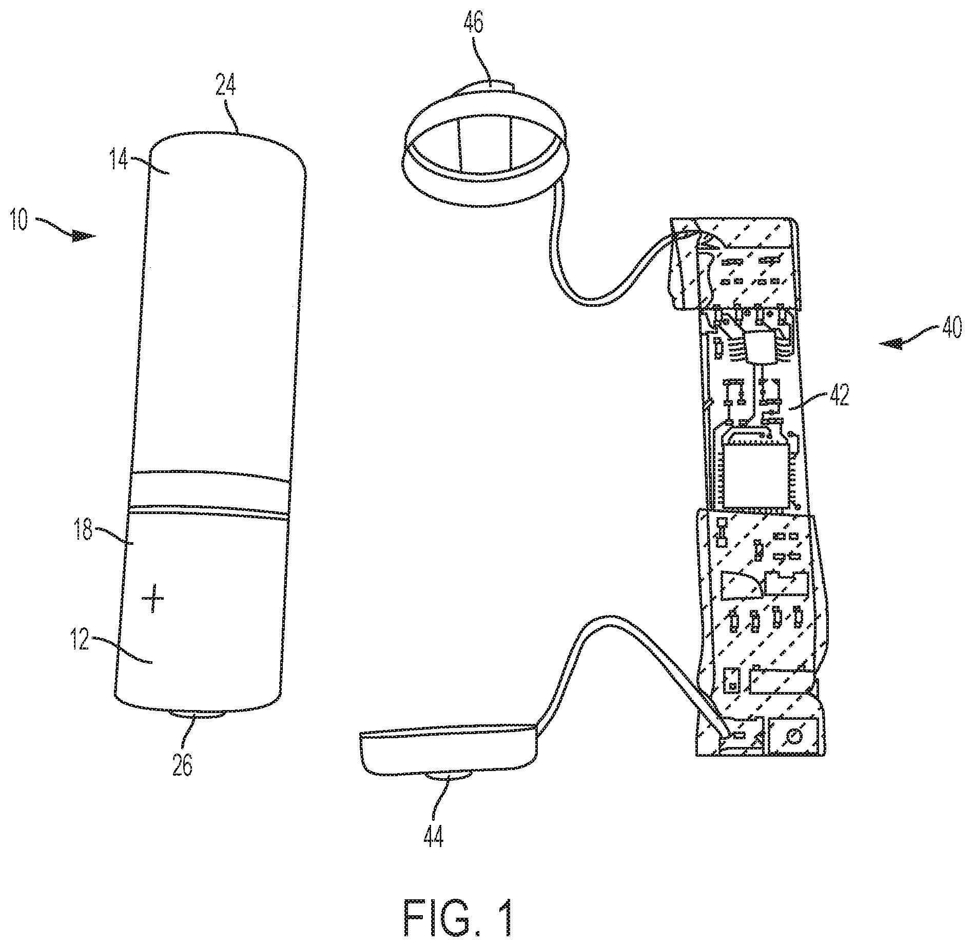
[0028] FIG. 1 is a top plan view of a battery cell and a reusable battery indicator constructed in accordance with the teachings of the disclosure, the battery cell and the reusable battery indicator being separated from one another.
[0029] FIG. 2 is a top plan view of the reusable battery indicator of FIG. 1 connected to the battery cell.
[0030] FIG. 3 is a close-up plan view of a printed circuit board of the reusable battery indicator of FIG. 1.
[0031] FIG. 4 is an electronic circuit schematic diagram of the reusable battery indicator of FIG. 1.
[0032] FIGS. 5A and 5B are top and bottom perspective views, respectively, of a second embodiment of a reusable battery indicator that is connected to a battery cell.
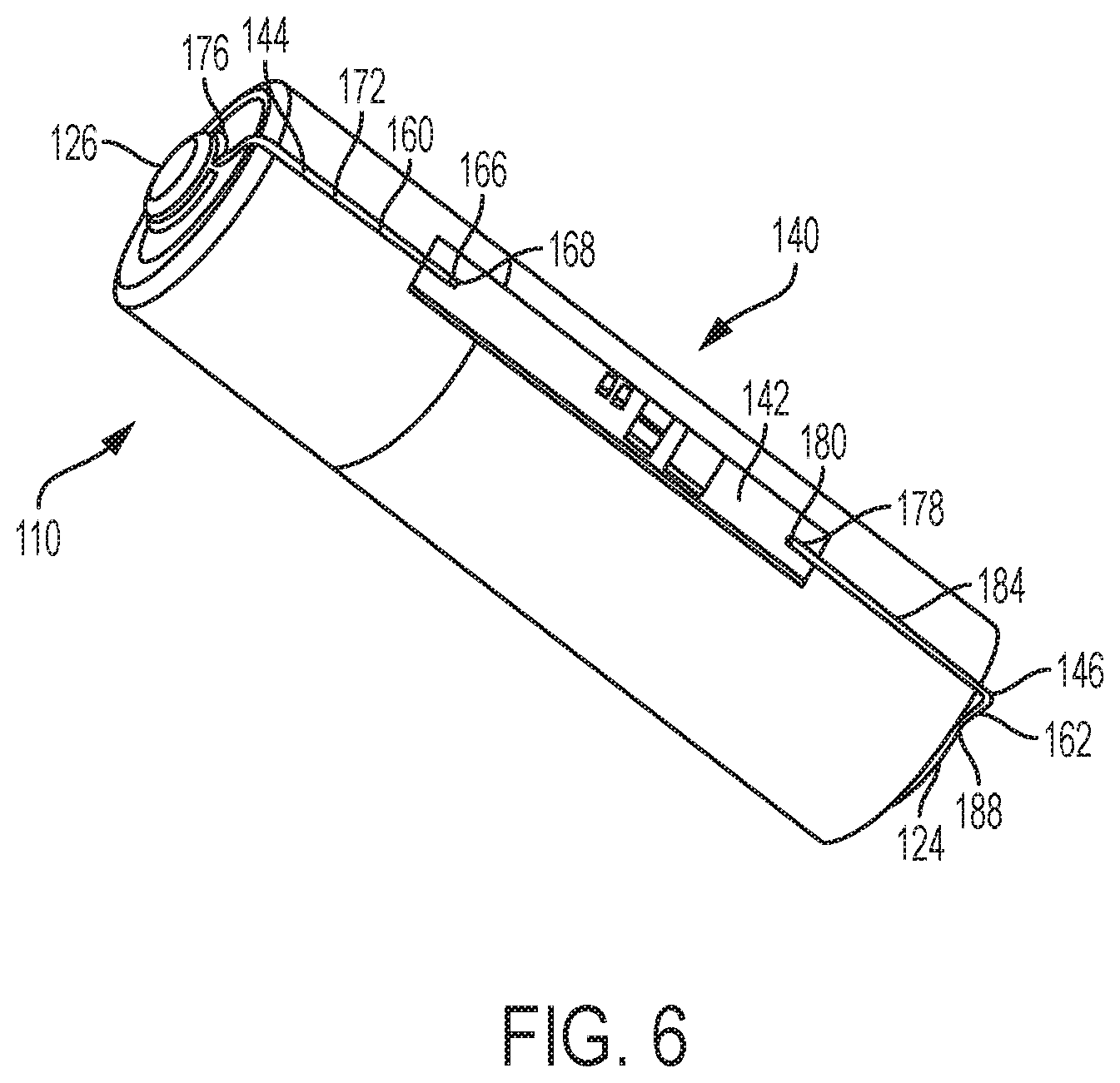
[0033] FIG. 6 is a top perspective view of a third embodiment of a reusable battery indicator that is connected to a battery cell.
[0034] FIGS. 7A and 7B are top and bottom perspective views, respectively, of a fourth embodiment of a reusable battery indicator that is connected to a battery cell.
[0035] FIGS. 8A and 8B are top and bottom perspective views, respectively, of a fifth embodiment of a reusable battery indicator that is connected to a battery cell.
[0036] FIG. 9 is a close-up cross-sectional view of a negative radial leaf at one end of the reusable battery indicator of FIGS. 8A and 8B.
[0037] FIG. 10 is a bottom perspective view of a battery compartment of an electronic device including two battery cells and a sixth embodiment of a reusable battery indicator that is connected to one of the battery cells.
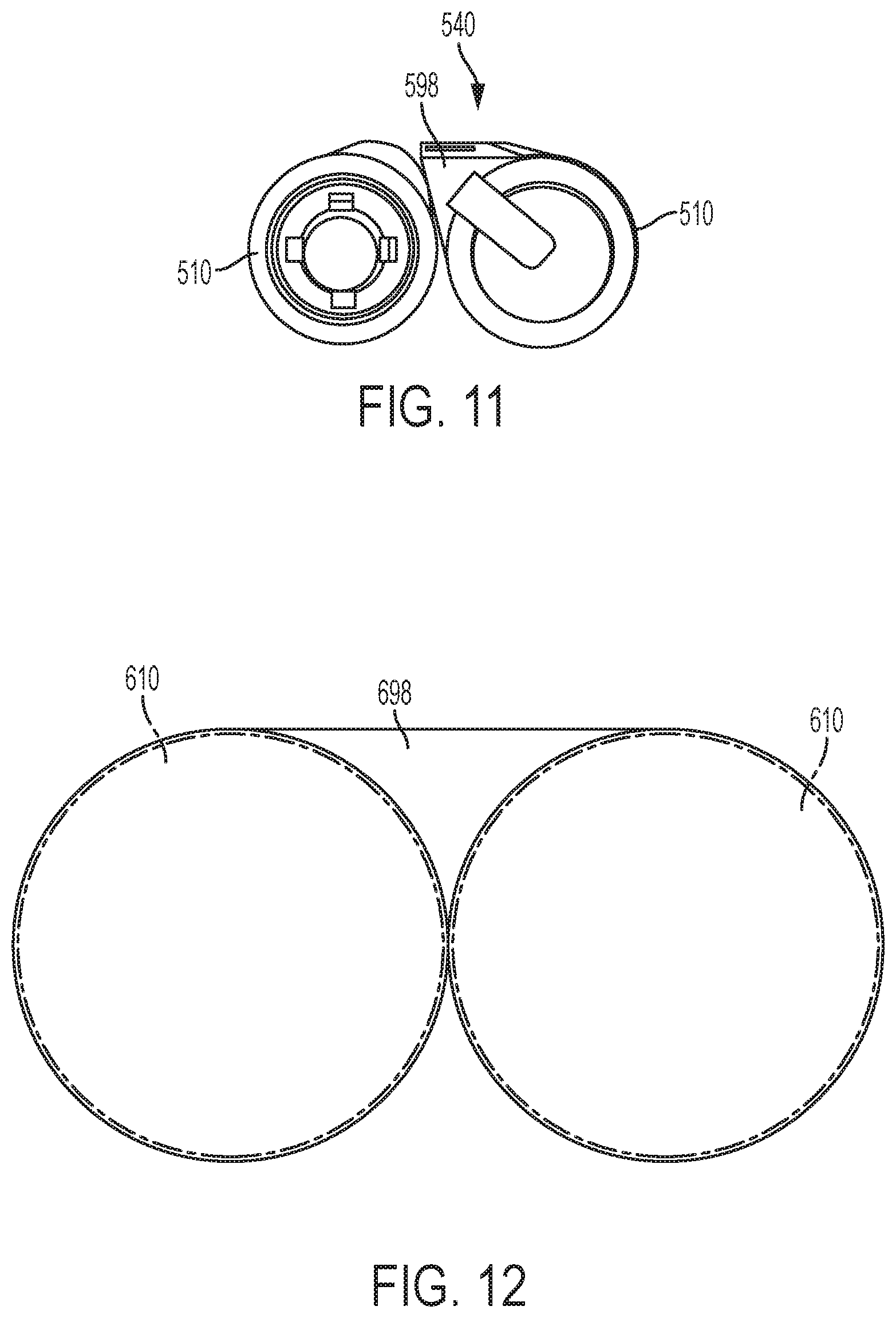
[0038] FIG. 11 is an end view of a seventh embodiment of a reusable battery indicator that is attached to one cell of a pair of battery cells.
[0039] FIG. 12 is a diagram of a eighth embodiment of a reusable battery indicator that is located between two adjacent battery cells.
[0040] FIG. 13 is a schematic diagram of a battery indication system including the reusable battery indicator of FIG. 1.
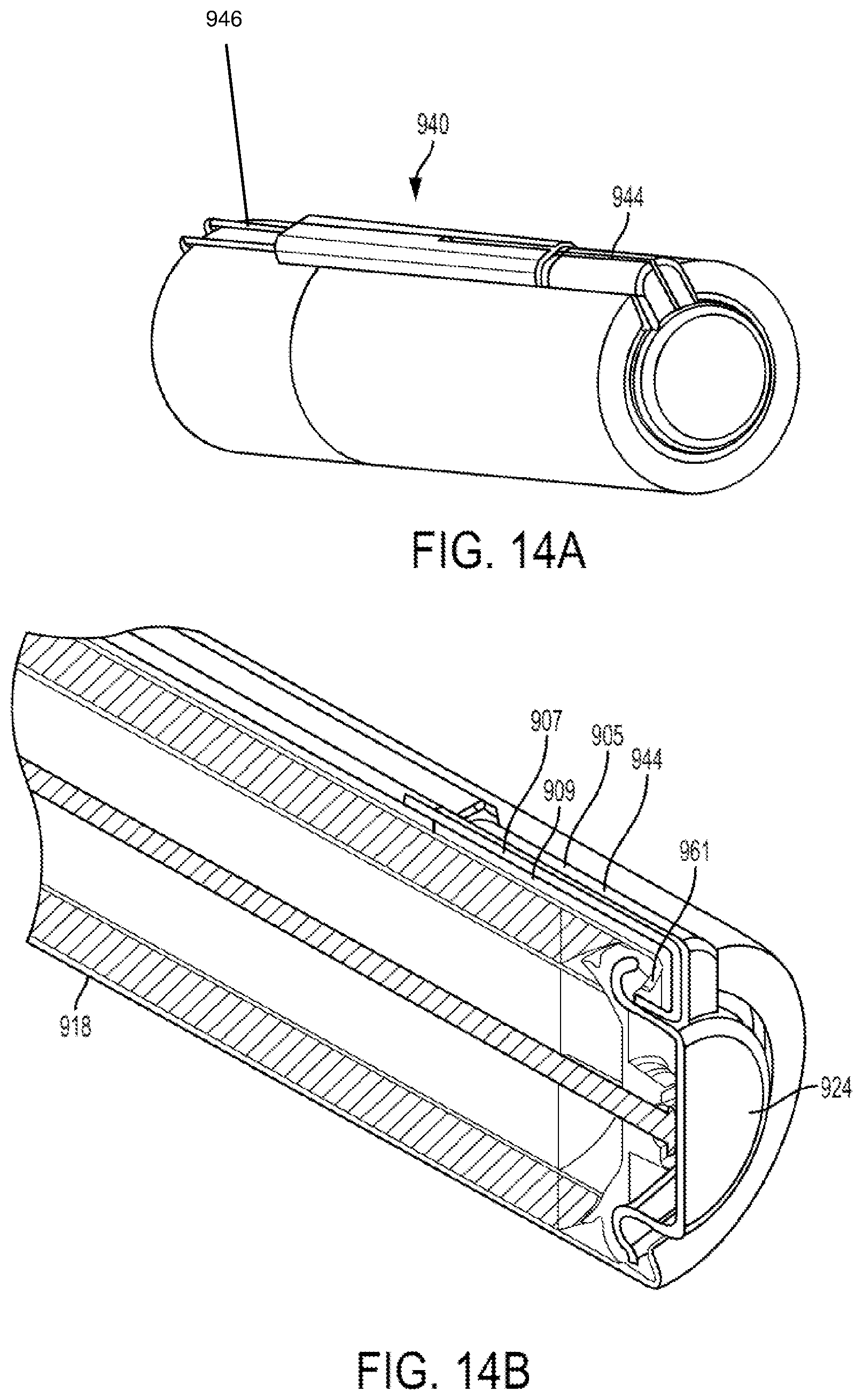
[0041] FIG. 14A is a perspective view of a ninth embodiment reusable battery indicator and a battery cell.
[0042] FIG. 14B is side cross-sectional view of the reusable battery indicator and battery cell of FIG. 14A.
DETAILED DESCRIPTION OF THE INVENTION
[0043] Electrochemical cells, or batteries, may be primary or secondary. Primary batteries are meant to be discharged, e.g., to exhaustion, only once and then discarded. Primary batteries (or disposable batteries) are described, for example, in David Linden, Handbook of Batteries (4th ed. 2011). Secondary batteries (or rechargeable batteries) are intended to be recharged and used over and over again. Secondary batteries may be discharged and recharged many times, e.g., more than fifty times, a hundred times, or more. Secondary batteries are described, for example, in David Linden, Handbook of Batteries (4.sup.th ed. 2011). Accordingly, batteries may include various electrochemical couples and electrolyte combinations. Although the description and examples provided herein are generally directed towards primary alkaline electrochemical cells, or batteries, it should be appreciated that the invention applies to both primary and secondary batteries of aqueous, nonaqueous, ionic liquid, and solid state systems. Primary and secondary batteries of the aforementioned systems are thus within the scope of this application and the invention is not limited to any particular embodiment.
[0044] Referring to FIGS. 1 and 2, a primary alkaline electrochemical cell, or battery cell 10, is illustrated that includes a cathode 12, an anode 14, and a housing 18. The battery cell 10 also includes an end cap 24. The end cap 24 serves as a negative terminal of the battery cell 10. A positive pip 26 is located at the opposite end of the battery cell 10 from the end cap 24. The positive pip 26 serves as a positive terminal of the battery cell 10. An electrolytic solution is dispersed throughout the battery cell 10. The battery cell 10 can be, for example, a AA, AAA, AAAA, C, or D alkaline battery. Additionally, in other embodiments, the battery cell 10 can be a 9V battery, a camera battery, a watch battery, or any other type of primary or secondary battery.
[0045] The housing 18 can be made of any suitable type of housing base material, for example cold-rolled steel or nickel-plated cold-rolled steel. In the embodiment illustrated in FIG. 1, the housing 18 may have a cylindrical shape. In other embodiments, the housing 18 may have any other suitable, non-cylindrical shape. The housing 18, for example, may have a shape comprising at least two parallel plates, such as a rectangular, square, or prismatic shape. The housing 18 may be, for example, deep-drawn from a sheet of the base material, such as cold-rolled steel or nickel-plated steel. The housing 18 may be, for example, drawn into a cylindrical shape. The housing 18 may have a sidewall. The interior surface of the sidewall of the housing 18 may be treated with a material that provides a low electrical-contact resistance between the interior surface of the sidewall of the housing 18 and an electrode, such as the cathode 12. The interior surface of the sidewall of the housing 18 may be plated, e.g., with nickel, cobalt, and/or painted with a carbon-loaded paint to decrease contact resistance between, for example, the internal surface of the sidewall of the housing 18 and the cathode 12.
[0046] Next to the battery cell 10 is one embodiment of a communication mechanism, such as a reusable battery indicator 40. The reusable battery indicator 40 includes an integrated circuit, which may be incorporated into a printed circuit board (PCB) 42, a first connector 44 that is electrically connected to the PCB 42, and a second connector 46 that is electrically connected to the PCB 42. The first connector 44 may be removably and electrically connected to the positive pip 26 to form a positive electrical connection and the second connector 46 may be removably and electrically connected to the end cap 24 to form a negative electrical connection, as illustrated in FIG. 2. The first connector 44 and the second connector 46 may take virtually any physical form that allows the first connector 44 and the second connector 46 to form electrical connections with the battery cell 10 and the PCB 42. In some embodiments, the first connector 44 and the second connector 46 may take any one or more of the following forms, a magnet, a cup, a sleeve, a tab, a socket, a pin, a washer, a spring connector, a wire loop, or any combination thereof. Moreover, the first connector 44 and the second connector 46 may be formed from virtually any material that transmits analog information, such as electrical information, from the battery cell to the PCB 42. For example, in some embodiments, the first connector 44 and the second connector 46 may be formed from one or more of the following materials, a metal, a metal alloy, cold-rolled steel, hard drawn ferrous and non-ferrous alloys, high and low carbon steel alloys, post or pre-plated ferrous and non-ferrous alloys, or any combination thereof. In some embodiments, at least one of the first connector 44 and the second connector 46 may comprise a metal and an insulator. More specifically, an inner surface of the first and second connectors 44, 46 may include a non-conductive coating (such as a polymer layer, epoxy, or passivate) or an additional insulator ring (e.g., paper, phenolic, or polymer) in areas other than contact areas for the terminals to guard against shorting to the battery housing or crimp.
[0047] Generally, the integrated circuit receives electrical information, such as amperes or volts from the first connector 44 and from the second connector 46, and the electrical information is used by the integrated circuit to calculate battery characteristic information, such as power or charge level, and the integrated circuit then transmits the battery characteristic information to a receiver, such as a computer, a smart phone, or a personal digital assistant, for use by the consumer. In this way, the reusable battery indicator 40 allows a consumer to acquire the battery characteristic information without removing the battery cell from an electronic device (or from a package). The first connector 44 and the second connector 46 deliver the electrical information to the integrated circuit without interfering with electrical contacts between the battery cell and the electronic device. Furthermore, the reusable battery indicator 40 is movable from one battery cell to another battery cell so as to be reused over and over again, thereby reducing the overall cost to a consumer.
[0048] Turning now to FIGS. 3 and 4, formed on the PCB 42 is an integrated circuit 48, that includes an embedded voltage sensor 50 within the integrated circuit 48 that is communicatively connected to the first connector 44 and to the second connector 46. The embedded voltage sensor 50 senses analog characteristics of the battery cell, such as amperes and voltage and converts the sensed analog characteristics to digital information. The PCB 42 also includes a communication circuit 52. An antenna 54 is operatively coupled to the communication circuit 52. The communication circuit 52 may comprise one or more of a radio-frequency identification circuit, a Bluetooth.RTM. circuit, a Bluetooth.RTM. low energy circuit, a Wi-Fi circuit, a Zigbee.RTM. circuit, a LORA circuit, and a Z-wave circuit. In one embodiment, an integrated circuit, such as a wireless Bluetooth Low-Energy voltage sensor, may incorporate the analog to digital converter, a microcontroller, a Bluetooth radio, a memory device, and a DC/DC voltage converter.
[0049] A voltage booster 56 is electrically connected to the integrated circuit 48 and the embedded voltage sensor 50. The embedded voltage sensor 50 and the voltage booster 56 are capable of reading the open circuit voltage of the battery that may be, for example, less than 1.8 volts. In some embodiments, the communication circuit 52 may comprise one or more of a thin disc BLE module, a UHF module, or a RF module.
[0050] In the embodiment illustrated in FIGS. 3 and 4, the integrated circuit 48, the voltage sensor 50, and the communication circuit 52 are all formed on the PCB 42, which is connected to the first connector 44 and the second connector 46. However, in other embodiments, the integrated circuit 48, the voltage sensor 50, and the communication circuit 52 may be formed as separate components that are communicatively and operatively connected to one another.
[0051] In the embodiment illustrated in FIGS. 5A and 5B, similar elements are numbered exactly 100 greater than elements numbered in FIGS. 1-4. For example, the battery cell is numbered 10 in FIGS. 1-4 and the battery cell is numbered 110 in FIGS. 5A and 5B. Unless stated otherwise, any element from any illustrated embodiment may be incorporated into any other illustrated embodiment.
[0052] Turning now to FIGS. 5A and 5B, a second embodiment of the reusable battery indicator 140 is attached to a battery cell 110. The reusable battery indicator 140 includes a PCB 142, a first connector 144, and a second connector 146. While the battery cell 110 in FIGS. 5A and 5B is illustrated as a AA size battery, the illustration is not intended to limit the reusable battery indicator 140 to the illustrated battery cell 110. Rather, the reusable battery indicator 140 may be sized and shaped to fit virtually any battery cell, especially those battery cell sizes listed elsewhere in the specification.
[0053] In the embodiment illustrated in FIGS. 5A and 5B, the first connector 144 and the second connector 146 comprise flexible wires 160, 162, respectively. The flexible wires 160, 162 may be formed as spring wires (from hard drawn ferrous and non-ferrous spring alloys) that capture the positive battery terminal 126 and the negative battery terminal 124, respectively, to transmit electrical characteristics, such as voltage and amperes, to the integrated circuit formed on the PCB 142. In the illustrated embodiment, the flexible wires 160, 162 are formed of ASTM A228 music wire with pre or post nickel plating to enhance conductivity, to reduce contact resistance, and to provide corrosion resistance.
[0054] In the embodiment illustrated in FIGS. 5A and 5B, the flexible wire 160 includes a first end 166, which is connected to a positive terminal 168 on the PCB 142 and a second end 170, which is also connected to the positive terminal 168 on the PCB 142. The flexible wire 160 includes a first leg 172, extending from the first end 166 and a second leg 174 extending from the second end 170. The first leg 172 and the second leg 174 are oriented substantially parallel to a longitudinal axis A of the battery cell 110. The first leg 172 and the second leg 174 are connected to one another at an end loop 176. The end loop 176 lies in a plane that is substantially perpendicular to the longitudinal axis of the battery cell 110. The end loop 176 is sized and shaped to fit around the positive terminal 126 of the battery cell 110. As a result, the flexible wire 160 forms a positive electrical pathway from the positive battery terminal 126 to the positive terminal 168 on the PCB 142. Moreover, the flexible wire 160 may be formed to produce a spring force that biases the flexible wire 160 into the attached position illustrated in FIGS. 5A and 5B, while allowing the flexible wire 160 to be temporarily deformed by a user to remove the reusable battery indicator 140 from the battery cell 110 when desired.
[0055] Similar to the flexible wire 160, the flexible wire 162 includes a first end 178, which is connected to a negative terminal 180 on the PCB 142 and a second end 182, which is also connected to the negative terminal 180 on the PCB 142. The flexible wire 162 includes a first leg 184, extending from the first end 178 and a second leg 186 extending from the second end 182. The first leg 184 and the second leg 186 are oriented substantially parallel to the longitudinal axis A of the battery cell 110. The first leg 184 and the second leg 186 are connected to one another at an end loop 188. The end loop 188 lies in a plane that is substantially perpendicular to the longitudinal axis of the battery cell 110. The end loop 186 is sized and shaped to fit around the negative terminal 124 of the battery cell 110. As a result, the flexible wire 162 forms a negative electrical pathway from the negative battery terminal 124 to the negative terminal 180 on the PCB 142. Moreover, the flexible wire 162 may be formed to produce a spring force that biases the flexible wire 162 into the attached position illustrated in FIGS. 5A and 5B, while allowing the flexible wire 162 to be temporarily deformed by a user to remove the reusable battery indicator 140 from the battery cell 110 when desired.
[0056] The approximately 90.degree. bends between the first and second legs 172, 174 of the first flexible wire 160 and the end loop 176 and between the first and second legs 184, 186 of the second flexible wire 162 and the end loop 188, create an axial force, which maintains the reusable battery indicator 140 in electrical connection with the battery cell 110. In other embodiments, the bends may be more than 90.degree. to mate to a tapered positive terminal.
[0057] In some embodiments, one or more of the first flexible wire 160 and the second flexible wire 162 may include a conductive magnet, or the one or more of the first flexible wire 160 and the second flexible wire 162 may be formed from conductive magnetic material, to provide additional retention force between the first flexible wire 160 and the positive terminal 126 and between the second flexible wire 162 and the negative terminal 124.
[0058] In other embodiments, one or more of the first flexible wire 160 and the second flexible wire 162 may be formed as a Kelvin connection, including separate power and sensing terminals, to measure impedance. Additionally, in alternate embodiments, the first flexible wire 160 and the second flexible wire 162 need not be formed as a single continuous wire, but may be formed as multiple wire pieces, for example, two wire pieces that are separated by a small distance in the end loop.
[0059] As in FIGS. 5A and 5B, in the embodiment of FIG. 6, similar elements are numbered exactly 100 greater than elements numbered in FIGS. 1-4. For example, the battery cell is numbered 10 in FIGS. 1-4 and the battery cell is numbered 110 in FIG. 6. Unless stated otherwise, any element from any illustrated embodiment may be incorporated into any other illustrated embodiment.
[0060] Turning now to FIG. 6, a third embodiment of the reusable battery indicator 140 is attached to a battery cell 110. The reusable battery indicator 140 includes a PCB 142, a first connector 144, and a second connector 146. While the battery cell 110 in FIG. 6 is illustrated as a AA size battery, the illustration is not intended to limit the reusable battery indicator 140 to the illustrated battery cell 110. Rather, the reusable battery indicator 140 may be sized and shaped to fit virtually any battery cell, especially those battery cell sizes listed elsewhere in the specification.
[0061] In the embodiment illustrated in FIG. 6, the first connector 144 and the second connector 146 comprise flexible wires 160, 162, respectively. The flexible wires 160, 162 may be formed as spring wires that capture the positive battery terminal 126 and the negative battery terminal 124, respectively, to transmit electrical characteristics, such as voltage and amperes, to the integrated circuit formed on the PCB 142.
[0062] The flexible wires 160, 162 in FIG. 6 are similar to the flexible wires of FIGS. 5A and 5B, except that the flexible wires 160, 162 in FIG. 6 have only a single leg. More specifically, the flexible wire 160 includes a first end 166, which is connected to a positive terminal 168 on the PCB 142. The flexible wire 160 includes a single leg 172, extending from the first end 166. The single leg 172 is oriented substantially parallel to a longitudinal axis A of the battery cell 110. The single leg 172 forms an end loop 176 at a second end. The end loop 176 lies in a plane that is substantially perpendicular to the longitudinal axis of the battery cell 110. The end loop also lies below the plane of the contact surface of the positive terminal 126. In this manner, the end loop 176 does not interfere with an electronic device making contact with the positive terminal 126. The end loop 176 is sized and shaped to fit around the positive terminal 126 of the battery cell 110. As a result, the flexible wire 160 forms a positive electrical pathway from the positive battery terminal 126 to the positive terminal 168 on the PCB 142. Moreover, the flexible wire 160 may be formed to produce a spring force that biases the flexible wire 160 into the attached position illustrated in FIG. 6, while allowing the flexible wire 160 to be temporarily deformed by a user to remove the reusable battery indicator 140 from the battery cell 110 when desired.
[0063] Similar to the flexible wire 160, the flexible wire 162 includes a first end 178, which is connected to a negative terminal 180 on the PCB 142. The flexible wire 162 includes a single leg 184, extending from the first end 178. The single leg 184 is oriented substantially parallel to the longitudinal axis A of the battery cell 110. The single leg 184 forms an end loop 188 at a second end. The end loop 188 lies in a plane that is substantially perpendicular to the longitudinal axis of the battery cell 110. The end loop 188 also lies below the plane of the contact surface of the negative terminal 124. In this manner, the end loop 188 does not interfere with an electronic device making contact with the negative terminal 124. The end loop 188 is sized and shaped to fit around the negative terminal 124 of the battery cell 110. As a result, the flexible wire 162 forms a negative electrical pathway from the negative battery terminal 124 to the negative terminal 180 on the PCB 142. Moreover, the flexible wire 162 may be formed to produce a spring force that biases the flexible wire 162 into the attached position illustrated in FIG. 6, while allowing the flexible wire 162 to be temporarily deformed by a user to remove the reusable battery indicator 140 from the battery cell 110 when desired.
[0064] In some embodiments, one or more of the first flexible wire 160 and the second flexible wire 162 may include a conductive magnet, or the one or more of the first flexible wire 160 and the second flexible wire 162 may be formed from conductive magnetic material, to provide additional retention force between the first flexible wire 160 and the positive terminal 126 and between the second flexible wire 162 and the negative terminal 124.
[0065] In other embodiments, one or more of the first flexible wire 160 and the second flexible wire 162 may be formed as a Kelvin connection, including separate power and sensing terminals, to measure impedance.
[0066] In the embodiment illustrated in FIGS. 7A and 7B, similar elements are numbered exactly 200 greater than elements numbered in FIGS. 1-4. For example, the battery cell is numbered 10 in FIGS. 1-4 and the battery cell is numbered 210 in FIGS. 7A and 7B. Unless stated otherwise, any element from any illustrated embodiment may be incorporated into any other illustrated embodiment.
[0067] Turning now to FIGS. 7A and 7B, a fourth embodiment of the reusable battery indicator 240 is attached to a battery cell 210. The reusable battery indicator 240 includes a PCB 242, a first connector 244, and a second connector 246. While the battery cell 210 in FIGS. 6A and 6B is illustrated as a AA size battery, the illustration is not intended to limit the reusable battery indicator 240 to the illustrated battery cell 210. Rather, the reusable battery indicator 240 may be sized and shaped to fit virtually any battery cell, especially those battery cell sizes listed elsewhere in the specification.
[0068] In the embodiment illustrated in FIGS. 7A and 7B, the first connector 244 and the second connector 246 comprise leaf springs 260, 262, respectively. The leaf springs 260, 262 may be formed as planar legs that capture the positive battery terminal 226 and the negative battery terminal 224, respectively, to transmit electrical characteristics, such as voltage and amperes, to the integrated circuit formed on the PCB 142.
[0069] In the embodiment illustrated in FIGS. 7A and 7B, the leaf spring 260 includes a first end 266, which is connected to a positive terminal 268 on the PCB 242. The leaf spring 260 includes a first leg 272, extending from the first end 266. The first leg 272 is substantially planar (or very slightly curved to mirror the curvature of the outer surface of the battery cell 210) and is oriented substantially parallel to the longitudinal axis of the battery cell 210. The first leg 272 turns approximately 90.degree. near a second end 273, forming an end clip 276. The end clip 276 lies in a plane that is substantially perpendicular to the longitudinal axis of the battery cell 210. The end clip 276 includes a concave end that is curved to mirror an outer cylindrical surface of the positive terminal 226 of the battery cell 210. As a result, the leaf spring 260 forms a positive electrical pathway from the positive battery terminal 226 to the positive terminal 268 on the PCB 242. Moreover, the leaf spring 260 may be formed to produce a spring force that biases the leaf spring 260 into the attached position illustrated in FIGS. 7A and 7B, while allowing the leaf spring 260 to be temporarily deformed by a user to remove the reusable battery indicator 240 from the battery cell 210 when desired.
[0070] Similar to the leaf spring 260, the leaf spring 262 includes a first end 278, which is connected to a negative terminal 280 on the PCB 242. The leaf spring 262 includes a first leg 284, extending from the first end 278. The first leg 284 is substantially planar (or very slightly curved to mirror the curvature of the outer surface of the battery cell 210) and is oriented substantially parallel to a longitudinal axis of the battery cell 210. The first leg 284 turns approximately 90.degree. near a second end 285, forming an end clip 288. The end clip 288 lies in a plane that is substantially perpendicular to the longitudinal axis of the battery cell 210. The end clip 288 includes a concave end that is curved to mirror an outer cylindrical surface of the negative terminal 224 of the battery cell 210. As a result, the leaf spring 262 forms a negative electrical pathway from the negative battery terminal 224 to the negative terminal 280 on the PCB 242. Moreover, the leaf spring 262 may be formed to produce a spring force that biases the leaf spring 262 into the attached position illustrated in FIGS. 7A and 7B, while allowing the leaf spring 262 to be temporarily deformed by a user to remove the reusable battery indicator 240 from the battery cell 210 when desired.
[0071] The approximately 90.degree. bends between the first leg 272 of the first leaf spring 260 and the end loop 276 and between the first leg 184 of the second leaf spring 262 and the end loop 288, create an axial force, which maintains the reusable battery indicator 240 in electrical connection with the battery cell 210.
[0072] In some embodiments, one or more of the first leaf spring 260 and the second leaf spring 262 may be integrated into the positive terminal 268 and the negative terminal 280, respectively, of the PCB 242 as one layer of a multi-layered PCB 242.
[0073] In some embodiments, the reusable battery indicator 240 may also include a retention clip 291 that extends from the reusable battery indicator 240 in a plane substantially perpendicular to the longitudinal axis of the battery cell 210. The retention clip 291 may include two opposing legs that are curved to mirror the curvature of the outer surface of the battery cell 210. The retention clip 291 provides additional retention force to retain the reusable battery indicator 240 on the battery cell 210.
[0074] In the embodiment illustrated in FIGS. 8A, 8B, and 9, similar elements are numbered exactly 300 greater than elements numbered in FIGS. 1-4. For example, the battery cell is numbered 10 in FIGS. 1-4 and the battery cell is numbered 310 in FIGS. 8A, 8B, and 9. Unless stated otherwise, any element from any illustrated embodiment may be incorporated into any other illustrated embodiment.
[0075] Turning now to FIGS. 8A, 8B, and 9, a fifth embodiment of the reusable battery indicator 340 is attached to a battery cell 310. The reusable battery indicator 340 includes a PCB 342, a first connector 344, and a second connector 346. While the battery cell 210 in FIGS. 8A and 8B is illustrated as a AA size battery, the illustration is not intended to limit the reusable battery indicator 340 to the illustrated battery cell 310. Rather, the reusable battery indicator 340 may be sized and shaped to fit virtually any battery cell, especially those battery cell sizes listed elsewhere in the specification.
[0076] Similar to the previous embodiment, in the embodiment illustrated in FIGS. 8A, 8B, and 9, the first connector 344 and the second connector 346 comprise first and second leaf springs 360, 362, respectively. The first and second leaf springs 360, 362 are similar to the first and second leaf springs 260, 262 of FIGS. 7A and 7B, with the following exceptions.
[0077] In the embodiment illustrated in FIGS. 8A, 8B, and 9, the first leaf spring 360 includes a retention clip 391 that extends in a plane that is substantially perpendicular to the longitudinal axis of the battery cell 310. In other embodiments, the second leaf spring 362 may include a similar retention clip. The retention clip 391 may include two opposing legs that are curved to mirror the curvature of the outer surface of the battery cell 310. The retention clip 391 provides additional retention force to retain the reusable battery indicator 340 on the battery cell 310.
[0078] Instead of including an end clip, the second leaf spring 346 includes an end loop 388. The end loop 388 lies in a plane that is substantially perpendicular to the longitudinal axis of the battery cell 310. The end loop 388 includes an inner opening 392 that is sized and shaped to mirror an outer cylindrical surface of the negative battery terminal 324. As a result, the second leaf spring 362 forms a negative electrical pathway from the negative battery terminal 324 to the negative terminal on the PCB 342.
[0079] In some embodiments, the end loop 388 may include a disc-shaped voltage sensor that is arranged to fit one end of the cylindrical battery cell 310.
[0080] Turning specifically now to FIG. 9, the end loop 388 may include a radial collar 394 that extends away from the end loop 388, towards the PCB 342. The radial collar 394 is sized and shaped to fit within a negative cap recess 396. The radial collar 394 provides negative terminal location and contact force, in addition to the end loop 388.
[0081] In other embodiments, a similar end loop with a radial collar may be formed in the first leaf spring for contact at the positive battery terminal. In such embodiments, the radial collar may provide additional clearance at the positive battery terminal where a reverse polarity insertion guard exists.
[0082] The end loop 388 and radial collar 394 cooperate with battery cells having a negative cap/positive crimp groove.
[0083] Turning now to FIG. 10, a sixth embodiment of a reusable battery indicator 440 is illustrated. In the embodiment of FIG. 10, the reusable battery indicator includes a housing 498, the integrated circuit, the voltage sensor, and the communication circuit being mounted within the housing 498. In the embodiment of FIG. 10, the housing 498 is sized and shaped to fit between two cylindrical battery cells 410 that are arranged longitudinally side-by-side. In the embodiment illustrated in FIG. 10, the housing 498 has a cross-section that is in the shape of a triangular prism. More specifically, the housing 498 has a first side 497 that is concave and a second side 499 that is concave. In other embodiments, the housing 498 may have a shape such as rectangular, trapezoid, elliptical, semi-circular, and variable, that fits within the void described by the triangular prism. In the embodiment of FIG. 10, the reusable battery indicator 440 is mounted between the battery cells 410 and within a battery receptacle 495 of an electronic device 500.
[0084] Turning now to FIG. 11, a seventh embodiment of a reusable battery indicator 540 is illustrated and located between two battery cells 510. In the embodiment of FIG. 11, the reusable battery indicator 540 includes a housing 598 that has only a single concave side.
[0085] FIG. 12 illustrates an alternative housing shape. In this embodiment, the housing 698 is arranged to fit in the void formed by two cylindrical battery cells 610 that are arranged side by side and oriented such that the respective longitudinal axes of the battery cells 610 are parallel to one another. In the embodiment illustrated in FIG. 12, the housing 698 has a cross-sectional shape that is defined by the following equation:
A.sub.v=(D.sub.B.sup.2-.PI./4.times.D.sub.B.sup.2)/2, where
[0086] A.sub.v is the cross-sectional area of the housing 698; and
[0087] D.sub.B is a diameter of one battery cell 610.
[0088] A housing having a cross-sectional shape defined by the preceding equation maximizes the usable space between the battery cells. For example, a housing having the cross-sectional shape defined above would result in the following housing volumes for the given battery sizes (assuming that the housing length was equal to the battery cell length). For a AAA battery, the housing would have a volume of 526 mm.sup.3; and for a AA battery, the housing would have a volume of 1140 mm.sup.3.
[0089] Turning now to FIG. 13, a computing device 800 is communicatively connected to the communication circuit in the reusable battery indicator 740. The computing device receives information from the communication circuit through wireless signals sent by the antenna in the reusable battery indicator 740. For example, the wireless signal may be one or more of a wifi signal, a Bluetooth.RTM. signal, a RFID signal, or any other wireless signal. In other embodiments, the computing device 800 and the reusable battery indicator 740 may communicatively connected by a wired connection.
[0090] The computing device 800 includes a processor 802 and a memory 804. The memory 804 may store processor executable instructions that when executed by the processor 802 cause the processor 802 to detect a wireless communication signal from the reusable battery indicator 740. In some embodiments the memory 804 may comprise a non-transitory computer readable medium with the processor executable instructions embedded thereon as an article of manufacture. The processor executable instructions may also cause the processor 802 to send wireless signals back to the reusable battery indicator 740 to remotely control battery circuitry through the reusable battery indicator 740. In this manner, the processor 802 may cause the reusable battery indicator 740 to determine battery characteristic data; and to send the battery characteristic data to a user interface, such as a display 806 on the computing device 800.
[0091] In some embodiments, the battery characteristic data may comprise at least one of an electrical capacity; a voltage; an impedance, a temperature, a current; an age, a charge/discharge cycle count, and a coulomb count.
[0092] In other embodiments, the processor executable instructions, when executed by the processor 802, causes the processor 802 to determine at least one of a battery type, a physical location of the battery, and an electrical device that the battery is powering by communicating with the reusable battery indicator 740.
[0093] Turning now to FIGS. 14A and 14B, yet another embodiment of a reusable battery indicator 940 is illustrated. The reusable battery indicator 940 includes a first connector 944 and a second connector 946. The first connector 944 connects to the negative terminal 924 of the battery 910 and the second connector 946 connects to the positive terminal of the battery 910. The first connector 944 includes an insulated leg 905 with an embedded wire 907. The insulated leg 905 includes an inner portion 909 that prevents the embedded wirer 907 from making contact with the crimped wall 961 of the battery housing 918. However, the embedded wire 907 is exposed at a radially inward end of the insulated leg 905 so that the embedded wire 907 may make electrical contact with the negative terminal 924, thus completing the electrical connection.
[0094] The dimensions and values disclosed herein are not to be understood as being strictly limited to the exact numerical values recited. Instead, unless otherwise specified, each such dimension is intended to mean both the recited value and a functionally equivalent range surrounding that value. For example, a dimension disclosed as "40 mm" is intended to mean "about 40 mm."
[0095] Every document cited herein, including any cross referenced or related patent or application and any patent application or patent to which this application claims priority or benefit thereof, is hereby incorporated herein by reference in its entirety unless expressly excluded or otherwise limited. The citation of any document is not an admission that it is prior art with respect to any invention disclosed or claimed herein or that it alone, or in any combination with any other reference or references, teaches, suggests or discloses any such invention. Further, to the extent that any meaning or definition of a term in this document conflicts with any meaning or definition of the same term in a document incorporated by reference, the meaning or definition assigned to that term in this document shall govern.
[0096] While particular embodiments of the present invention have been illustrated and described, it would be obvious to those skilled in the art that various other changes and modifications can be made without departing from the spirit and scope of the invention. It is therefore intended to cover in the appended claims all such changes and modifications that are within the scope of this invention.
* * * * *
D00000
D00001
D00002
D00003
D00004
D00005
D00006
D00007
D00008
D00009
XML
uspto.report is an independent third-party trademark research tool that is not affiliated, endorsed, or sponsored by the United States Patent and Trademark Office (USPTO) or any other governmental organization. The information provided by uspto.report is based on publicly available data at the time of writing and is intended for informational purposes only.
While we strive to provide accurate and up-to-date information, we do not guarantee the accuracy, completeness, reliability, or suitability of the information displayed on this site. The use of this site is at your own risk. Any reliance you place on such information is therefore strictly at your own risk.
All official trademark data, including owner information, should be verified by visiting the official USPTO website at www.uspto.gov. This site is not intended to replace professional legal advice and should not be used as a substitute for consulting with a legal professional who is knowledgeable about trademark law.