Camera Lens Assembly
WENREN; Jianke ; et al.
U.S. patent application number 16/834072 was filed with the patent office on 2020-07-16 for camera lens assembly. This patent application is currently assigned to Zhejiang Sunny Optical Co., Ltd. The applicant listed for this patent is Zhejiang Sunny Optical Co., Ltd. Invention is credited to Lingbo HE, Yuhao WANG, Jianke WENREN.
| Application Number | 20200225452 16/834072 |
| Document ID | / |
| Family ID | 63470259 |
| Filed Date | 2020-07-16 |


View All Diagrams
| United States Patent Application | 20200225452 |
| Kind Code | A1 |
| WENREN; Jianke ; et al. | July 16, 2020 |
CAMERA LENS ASSEMBLY
Abstract
The present disclosure discloses a camera lens assembly including, sequentially from an object side to an image side along an optical axis, a first lens, a second lens, a third lens, a fourth lens, a fifth lens and a sixth lens. The first lens has a positive refractive power; the second lens has a positive refractive power; the third lens has a refractive power; the fourth lens has a refractive power and an object-side surface thereof is a convex surface; the fifth lens has a positive refractive power; and the sixth lens has a negative refractive power. Half of a diagonal length ImgH of an effective pixel area on an imaging plane of the camera lens assembly and a total effective focal length f of the camera lens assembly satisfy 0.4<ImgH/f<0.6.
| Inventors: | WENREN; Jianke; (Ningbo City, CN) ; HE; Lingbo; (Ningbo City, CN) ; WANG; Yuhao; (Ningbo City, CN) | ||||||||||
| Applicant: |
|
||||||||||
|---|---|---|---|---|---|---|---|---|---|---|---|
| Assignee: | Zhejiang Sunny Optical Co.,
Ltd Ningbo City CN |
||||||||||
| Family ID: | 63470259 | ||||||||||
| Appl. No.: | 16/834072 | ||||||||||
| Filed: | March 30, 2020 |
Related U.S. Patent Documents
| Application Number | Filing Date | Patent Number | ||
|---|---|---|---|---|
| PCT/CN2019/077465 | Mar 8, 2019 | |||
| 16834072 | ||||
| Current U.S. Class: | 1/1 |
| Current CPC Class: | G02B 9/62 20130101; G02B 13/0045 20130101 |
| International Class: | G02B 13/00 20060101 G02B013/00; G02B 9/62 20060101 G02B009/62 |
Foreign Application Data
| Date | Code | Application Number |
|---|---|---|
| Jun 5, 2018 | CN | 201810570519.1 |
Claims
1. A camera lens assembly, comprising: a first lens, a second lens, a third lens, a fourth lens, a fifth lens and a sixth lens, which are sequentially arranged from an object side of the camera lens assembly to an image side of the camera lens assembly along an optical axis of the camera lens assembly, wherein, the first lens has a positive refractive power; the second lens has a positive refractive power; the third lens has a refractive power; the fourth lens has a refractive power and an object-side surface of the fourth lens is a convex surface; the fifth lens has a positive refractive power, and the sixth lens has a negative refractive power; wherein 0.4<ImgH/f<0.6, where ImgH is half of a diagonal length of an effective pixel area on an imaging plane of the camera lens assembly and f is a total effective focal length of the camera lens assembly.
2. The camera lens assembly according to claim 1, wherein 2<f1/(R1+R2)<4.5, where f1 is an effective focal length of the first lens, R1 is a radius of curvature of an object-side surface of the first lens and R2 is a radius of curvature of an image-side surface of the first lens.
3. The camera lens assembly according to claim 1, wherein 1.5<f2/|R3|<2.5, where f2 is an effective focal length of the second lens and R3 is a radius of curvature of an object-side surface of the second lens.
4. The camera lens assembly according to claim 1, wherein -2.5<f5/f6<-1.5, where f5 is an effective focal length of the fifth lens and f6 is an effective focal length of the sixth lens.
5. The camera lens assembly according to claim 1, wherein 0.2<R8/R7.ltoreq.1, where R7 is a radius of curvature of the object-side surface of the fourth lens and R8 is a radius of curvature of an image-side surface of the fourth lens.
6. The camera lens assembly according to claim 1, wherein 1<|f5/R9|<2, where f5 is an effective focal length of the fifth lens and R9 is a radius of curvature of an object-side surface of the fifth lens.
7. The camera lens assembly according to claim 1, wherein 0.6<T45/T34+CT4)<1.5, where T45 is a spaced distance between the fourth lens and the fifth lens on the optical axis, T34 is a spaced distance between the third lens and the fourth lens on the optical axis and CT4 is a center thickness of the fourth lens on the optical axis.
8. The camera lens assembly according to claim 1, wherein 2<CT2/CT1<2.5, where CT1 is a center thickness of the first lens on the optical axis and CT2 is a center thickness of the second lens on the optical axis.
9. The camera lens assembly according to claim 1, wherein 1 mm<DT11.times.DT21/DT51<2 mm, where DT11 is a maximum effective radius of an object-side surface of the first lens, DT21 is a maximum effective radius of an object-side surface of the second lens and DT51 is a maximum effective radius of an object-side surface of the fifth lens.
10. The camera lens assembly according to claim 1, wherein 1.5<|f56/f123|<4, where f56 is a combined focal length of the fifth lens and the sixth lens and f123 is a combined focal length of the first lens, the second lens and the third lens.
11. The camera lens assembly according to claim 1, wherein TTL/f<1.1, where TTL is a distance on the optical axis from the object-side surface of the first lens to the imaging plane of the camera lens assembly and f is the total effective focal length of the camera lens assembly.
12. A camera lens assembly, comprising: a first lens, a second lens, a third lens, a fourth lens, a fifth lens and a sixth lens, which are sequentially arranged from an object side of the camera lens assembly to an image side of the camera lens assembly along an optical axis of the camera lens assembly, wherein, the first lens has a positive refractive power and an image-side surface of the first lens is a concave surface; the second lens has a positive refractive power and an object-side surface of the second lens is a convex surface; the third lens has a refractive power; the fourth lens has a refractive power; the fifth lens has a positive refractive power and an object-side surface of the fifth lens is a concave surface; and the sixth lens has a negative refractive power; wherein 20.degree.<HFOV<30.degree., where HFOV is half of a maximal field-of-view of the camera lens assembly.
13. The camera lens assembly according to claim 12, wherein 2<f1/(R1+R2)<4.5, where f1 is an effective focal length of the first lens, R1 is a radius of curvature of an object-side surface of the first lens and R2 is a radius of curvature of the image-side surface of the first lens.
14. The camera lens assembly according to claim 12, wherein 1.5<f2/|R3|2.5, where f2 is an effective focal length of the second lens and R3 is a radius of curvature of the object-side surface of the second lens.
15. The camera lens assembly according to claim 12, wherein 0.6<T45/(T34+CT4)<1.5, where T45 is a spaced distance between the fourth lens and the fifth lens on the optical axis, T34l is a spaced distance between the third lens and the fourth lens on the optical axis and CT4 is a center thickness of the fourth lens on the optical axis.
16. The camera lens assembly according to claim 12, wherein 2<CT2/CT1<5, where CT1 is a center thickness of the first lens on the optical axis and CT2 is a center thickness of the second lens on the optical axis.
17. The camera lens assembly according to claim 12, wherein 1.5<|f56/f123|<4, where f56 is a combined focal length of the fifth lens and the sixth lens and f123 is a combined focal length of the first lens, the second lens and the third lens.
18. The camera lens assembly according to claim 12, wherein 1 mm<DT11.times.DT21/DT51<2 mm, where DT11 is a maximum effective radius of an object-side surface of the first lens, DT21 is a maximum effective radius of the object-side surface of the second lens and DT51 is a maximum effective radius of the object-side surface of the fifth lens.
19. The camera lens assembly according to claim 12, wherein -2.5<f5/f6<-1.5, where f5 is an effective focal length of the fifth lens and f6 is an effective focal length of the sixth lens.
20. The camera lens assembly according to claim 13, wherein TTL/f<1.1, where TTL is a distance on the optical axis from the object-side surface of the first lens to an imaging plane of the camera lens assembly and f is a total effective focal length of the camera lens assembly.
Description
CROSS-REFERENCE TO RELATED APPLICATIONS
[0001] The present patent application is a continuation of International Application No. PCT/CN2019/077465, filed on Mar. 8, 2019, which claims priority to Chinese Patent Application No. 201810570519.1, filed in the China National Intellectual Property Administration (CNIPA) on Jun. 5, 2018. Both of the aforementioned patent applications are hereby incorporated by reference in their entireties.
TECHNICAL FIELD
[0002] The present disclosure relates to a camera lens assembly, and more specifically, relates to a camera lens assembly including six lenses.
BACKGROUND
[0003] With the advancement of science and technology and the rapid development of portable electronic products such as smart phones, people are increasingly demanding the shooting functions of portable electronic products. In order to meet the shooting needs of various scenes, the camera lens assembly of smart-phones has gradually developed from a single camera to a multi-camera, such as a dual camera formed by a combination of a wide-angle lens assembly and a telephoto lens assembly, to achieve the function of optical zoom.
[0004] At present, the existing telephoto lens assemblies on the market generally cannot take into account aspects such as large image surface, long focal length, small aberrations, and high image quality, and thus may not meet the requirements of the dual-camera technology for telephoto lens assemblies.
SUMMARY
[0005] The present disclosure provides a camera lens assembly, for example, a camera lens assembly that may be applied as a telephoto lens assembly to a dual-camera technology, that is applicable to portable electronic products and at least solves or partially addresses at least one of the above disadvantages of the prior art.
[0006] In one aspect, the present disclosure provides a camera lens assembly which includes, sequentially from an object side to an image side along an optical axis, a first lens, a second lens, a third lens, a fourth lens, a fifth lens and a sixth lens. The first lens may have a positive refractive power; the second lens may have a positive refractive power; the third lens has a positive refractive power or a negative refractive power; the fourth lens has a positive refractive power or a negative refractive power, and an object-side surface thereof may be a convex surface; the fifth lens may have a positive refractive power; and the sixth lens may have a negative refractive power.
[0007] In one embodiment, half of a diagonal length ImgH of an effective pixel area on an imaging plane of the camera lens assembly and a total effective focal length f of the camera lens assembly may satisfy 0.4<ImgH/f<0.6.
[0008] In one embodiment, an effective focal length f1 of the first lens, a radius of curvature R1 of an object-side surface of the first lens and a radius of curvature R2 of an image-side surface of the first lens may satisfy 2<f1/(R1+R2)<4.5.
[0009] In one embodiment, an effective focal length f2 of the second lens and a radius of curvature R3 of an object-side surface of the second lens may satisfy 1.5<f2/|R3|<2.5.
[0010] In one embodiment, an effective focal length f5 of the fifth lens and an effective focal length f6 of the sixth lens may satisfy -2.5<f5/f6<-1.5.
[0011] In one embodiment, a radius of curvature R7 of the object-side surface of the fourth lens and a radius of curvature R8 of an image-side surface of the fourth lens may satisfy 0.2<R8/R7.ltoreq.1.
[0012] In one embodiment, an effective focal length f5 of the fifth lens and a radius of curvature R9 of an object-side surface of the fifth lens may satisfy 1<|f5/R9|<2.
[0013] In one embodiment, a distance TTL on the optical axis from an object-side surface of the first lens to an imaging plane of the camera lens assembly and a total effective focal length f of the camera lens assembly may satisfy TTL/f<1.1.
[0014] In one embodiment, a spaced distance T45 between the fourth lens and the fifth lens on the optical axis, a spaced distance T34 between the third lens and the fourth lens on the optical axis and a center thickness CT4 of the fourth lens on the optical axis may satisfy 0.6<T45/(T34+CT4)<1.5.
[0015] In one embodiment, a center thickness CT1 of the first lens on the optical axis and a center thickness CT2 of the second lens on the optical axis may satisfy 2<CT2/CT1<2.5.
[0016] In one embodiment, a combined focal length f56 of the fifth lens and the sixth lens and a combined focal length f123 of the first lens, the second lens and the third lens may satisfy 1.5<f56/f123|<4.
[0017] In one embodiment, a maximum effective radius DT11 of an object-side surface of the first lens, a maximum effective radius DT21 of an object-side surface of the second lens and a maximum effective radius DT51 of an object-side surface of the fifth lens may satisfy 1 mm<DT11.times.DT21/DT51<2 mm.
[0018] In one embodiment, half of a maximal field-of-view HFOV of the camera lens assembly may satisfy 20.degree.<HFOV<30.degree..
[0019] In one embodiment, an image-side surface of the first lens may be a concave surface, an object-side surface of the second lens may be a convex surface and an object-side surface of the fifth lens may be a concave surface.
[0020] In another aspect, the present disclosure provides a camera lens assembly which includes, sequentially from an object side to an image side along an optical axis, a first lens, a second lens, a third lens, a fourth lens, a fifth lens and a sixth lens. The first lens may have a positive refractive power, and an image-side surface thereof may be a concave surface; the second lens may have a positive refractive power, and an object-side surface thereof may be a convex surface; the third lens has a positive refractive power or a negative refractive power; the fourth lens has a positive refractive power or a negative refractive power; the fifth lens may have a positive refractive power, and an object-side surface thereof may be a concave surface; and the sixth lens may have a negative refractive power. Here, half of a maximal field-of-view HFOV of the camera lens assembly may satisfy 20.degree.<HFOV<30.degree..
[0021] The present disclosure employs a plurality of (for example, six) lenses, and the camera lens assembly has at least one advantageous effect such as long focal length, large image surface, small aberration and high image quality and the like by rationally assigning the refractive power, the surface shape, the center thickness of each lens, and the on-axis spaced distance between the lenses and the like.
BRIEF DESCRIPTION OF THE DRAWINGS
[0022] Other features, objects, and advantages of the present disclosure will become more apparent from the following detailed description of the non-limiting embodiments with reference to the accompanying drawings. In the accompanying drawings:
[0023] FIG. 1 illustrates a schematic structural view of a camera lens assembly according to Example 1 of the present disclosure;
[0024] FIGS. 2A to 2D illustrate a longitudinal aberration curve, an astigmatic curve, a distortion curve and a lateral color curve of the camera lens assembly of the Example 1, respectively;
[0025] FIG. 3 illustrates a schematic structural view of a camera lens assembly according to Example 2 of the present disclosure;
[0026] FIGS. 4A to 4D illustrate a longitudinal aberration curve, an astigmatic curve, a distortion curve and a lateral color curve of the camera lens assembly of the Example 2, respectively;
[0027] FIG. 5 illustrates a schematic structural view of a camera lens assembly according to Example 3 of the present disclosure;
[0028] FIGS. 6A to 6D illustrate a longitudinal aberration curve, an astigmatic curve, a distortion curve and a lateral color curve of the camera lens assembly of the Example 3, respectively;
[0029] FIG. 7 illustrates a schematic structural view of a camera lens assembly according to Example 4 of the present disclosure;
[0030] FIGS. 8A to 8D illustrate a longitudinal aberration curve, an astigmatic curve, a distortion curve and a lateral color curve of the camera lens assembly of the Example 4, respectively;
[0031] FIG. 9 illustrates a schematic structural view of a camera lens assembly according to Example 5 of the present disclosure;
[0032] FIGS. 10A to 10D illustrate a longitudinal aberration curve, an astigmatic curve, a distortion curve and a lateral color curve of the camera lens assembly of the Example 5, respectively;
[0033] FIG. 11 illustrates a schematic structural view of a camera lens assembly according to Example 6 of the present disclosure;
[0034] FIGS. 12A to 12D illustrate a longitudinal aberration curve, an astigmatic curve, a distortion curve and a lateral color curve of the camera lens assembly of the Example 6, respectively;
[0035] FIG. 13 illustrates a schematic structural view of a camera lens assembly according to Example 7 of the present disclosure;
[0036] FIGS. 14A to 14D illustrate a longitudinal aberration curve, an astigmatic curve, a distortion curve and a lateral color curve of the camera lens assembly of the Example 7, respectively;
[0037] FIG. 15 illustrates a schematic structural view of a camera lens assembly according to Example 8 of the present disclosure;
[0038] FIGS. 16A to 16D illustrate a longitudinal aberration curve, an astigmatic curve, a distortion curve and a lateral color curve of the camera lens assembly of the Example 8, respectively;
[0039] FIG. 17 illustrates a schematic structural view of a camera lens assembly according to Example 9 of the present disclosure;
[0040] FIGS. 18A to 18D illustrate a longitudinal aberration curve, an astigmatic curve, a distortion curve and a lateral color curve of the camera lens assembly of the Example 9, respectively;
[0041] FIG. 19 illustrates a schematic structural view of a camera lens assembly according to Example 10 of the present disclosure;
[0042] FIGS. 20A to 20D illustrate a longitudinal aberration curve, an astigmatic curve, a distortion curve and a lateral color curve of the camera lens assembly of the Example 10, respectively;
[0043] FIG. 21 illustrates a schematic structural view of a camera lens assembly according to Example 11 of the present disclosure;
[0044] FIGS. 22A to 22D illustrate a longitudinal aberration curve, an astigmatic curve, a distortion curve and a lateral color curve of the camera lens assembly of the Example 11, respectively;
DETAILED DESCRIPTION OF EMBODIMENTS
[0045] For a better understanding of the present disclosure, various aspects of the present disclosure will be described in more detail with reference to the accompanying drawings. It should be understood that the detailed description is merely illustrative of the exemplary embodiments of the present disclosure and is not intended to limit the scope of the present disclosure in any way. Throughout the specification, the same reference numerals refer to the same elements. The expression "and/or" includes any and all combinations of one or more of the associated listed items.
[0046] It should be noted that in the present specification, the expressions such as first, second, third are used merely for distinguishing one feature from another, without indicating any limitation on the features. Thus, a first lens discussed below may also be referred to as a second lens or a third lens without departing from the teachings of the present disclosure.
[0047] In the accompanying drawings, the thickness, size and shape of the lens have been slightly exaggerated for the convenience of explanation. In particular, shapes of spherical surfaces or aspheric surfaces shown in the accompanying drawings are shown by way of example. That is, shapes of the spherical surfaces or the aspheric surfaces are not limited to the shapes of the spherical surfaces or the aspheric surfaces shown in the accompanying drawings. The accompanying drawings are merely illustrative and not strictly drawn to scale.
[0048] Herein, the paraxial area refers to an area near the optical axis. If a surface of a lens is a convex surface and the position of the convex is not defined, it indicates that the surface of the lens is convex at least in the paraxial region; and if a surface of a lens is a concave surface and the position of the concave is not defined, it indicates that the surface of the lens is concave at least in the paraxial region. In each lens, the surface closest to the object side is referred to as an object-side surface of the lens, and the surface closest to the imaging plane is referred to as an image-side surface of the lens.
[0049] It should be further understood that the terms "comprising," "including," "having," "containing" and/or "contain," when used in the specification, specify the presence of stated features, elements and/or components, but do not exclude the presence or addition of one or more other features, elements, components and/or combinations thereof. In addition, expressions, such as "at least one of," when preceding a list of features, modify the entire list of features rather than an individual element in the list. Further, the use of "may," when describing embodiments of the present disclosure, refers to "one or more embodiments of the present disclosure." Also, the term "exemplary" is intended to refer to an example or illustration.
[0050] Unless otherwise defined, all terms (including technical and scientific terms) used herein have the same meaning as commonly understood by those of ordinary skill in the art to which the present disclosure belongs. It will be further understood that terms, such as those defined in commonly used dictionaries, should be interpreted as having a meaning that is consistent with the meaning in the context of the relevant art and will not be interpreted in an idealized or overly formal sense, unless expressly so defined herein.
[0051] It should also be noted that, the examples in the present disclosure and the features in the examples may be combined with each other on a non-conflict basis. The present disclosure will be described in detail below with reference to the accompanying drawings and in combination with the examples. The features, principles, and other aspects of the present disclosure are described in detail below.
[0052] A camera lens assembly according to an exemplary embodiment of the present disclosure may include, for example, six lenses having refractive power, i.e. a first lens, a second lens, a third lens, a fourth lens, a fifth lens and a sixth lens. The six lenses are arranged sequentially from an object side to an image side along an optical axis, and an air gap may be provided between each adjacent lens.
[0053] In an exemplary embodiment, the first lens may have a positive refractive power; the second lens may have a positive refractive power; the third lens has a positive refractive power or a negative refractive power; the fourth lens has a positive refractive power or a negative refractive power, and an object-side surface thereof may be a convex surface; the fifth lens may have a positive refractive power; and the sixth lens may have a negative refractive power.
[0054] In an exemplary embodiment, an object-side surface of the first lens may be a convex surface, and an image-side surface of the first lens may be a concave surface. An object-side surface of the second lens may be a convex surface. An image-side surface of the third lens may be a concave surface. An image-side surface of the fourth lens may be a concave surface. An object-side surface of the fifth lens may be a concave surface, and an image-side surface of the fifth lens may be a convex surface. An image-side surface of the sixth lens may be a concave surface.
[0055] By controlling the surface shape of each lens in the camera lens assembly, the assembly stability of the camera lens assembly is advantageously ensured, which is in turn to conducive to the mass production of the lens assembly. At the same time, reasonable surface arrangement is beneficial to improve the image quality of the camera lens assembly.
[0056] In an exemplary embodiment, the camera lens assembly according to the present disclosure may satisfy: 20.degree.<HFOV<30.degree., where HFOV is half of a maximal field-of-view of the camera lens assembly. More specifically, HFOV may further satisfy: 25.degree.<HFOV<30.degree., for example, 24.7.degree..ltoreq.HFOV.ltoreq.28.6.degree.. When the conditional expression of 20.degree.<HFOV<30.degree. is satisfied, the full field-of-view of the camera lens assembly may be ensured to be less than 60 degrees, and the imaging effect may be improved.
[0057] In an exemplary embodiment, the camera lens assembly according to the present disclosure may satisfy: 0.4<ImgH/f<0.6, where ImgH is half of a diagonal length of an effective pixel area on an imaging plane of the camera lens assembly and f is a total effective focal length of the camera lens assembly. More specifically, ImgH and f may further satisfy: 0.48.ltoreq.ImgH/f.ltoreq.0.57. By controlling the ratio of ImgH to f, the telephoto ratio of the camera lens assembly may be effectively improved, the magnification of the shooting may be increased, and the image quality may be improved.
[0058] In an exemplary embodiment, the camera lens assembly according to the present disclosure may satisfy: 2<f1/(R1+R2)<4.5, where f1 is an effective focal length of the first lens, R1 is a radius of curvature of an object-side surface of the first lens and R2 is a radius of curvature of an image-side surface of the first lens. More specifically, f1, R1 and R2 may further satisfy: 2.2.gtoreq.f1/(R1+R2).ltoreq.3.8, for example, 2.45.gtoreq.f1/(R1+R2).ltoreq.3.55. When the conditional expression of 2<f1/(R1+R2)<4.5 is satisfied, the overall focal length of the lens assembly may be effectively increased, and the refractive power of the first lens may be reasonably assigned, which reduces the processing sensitivity of the actual parts.
[0059] In an exemplary embodiment, the camera lens assembly according to the present disclosure may satisfy: 1.5<f2/|R3|<2.5, where f2 is an effective focal length of the second lens and R3 is a radius of curvature of an object-side surface of the second lens. More specifically, f2 and R3 may further satisfy: 1.60.ltoreq.f2/|R3|.ltoreq.2.30, for example, 1.77.ltoreq.f2/|R3|.ltoreq.2.16. Reasonably assigning the refractive power of the second lens is beneficial to ensure that the full field-of-view of the camera lens assembly is less than 60 degrees and improve the imaging effect.
[0060] In an exemplary embodiment, the camera lens assembly according to the present disclosure may satisfy: -2.5<f5/f6<-1.5, where f5 is an effective focal length of the fifth lens and f6 is an effective focal length of the sixth lens. More specifically, f5 and f6 may further satisfy: -2.45.ltoreq.f5/f6.ltoreq.-1.59. By controlling the effective focal lengths of the fifth lens and the sixth lens, the optical distortion of the camera lens assembly may be reduced.
[0061] In an exemplary embodiment, the camera lens assembly according to the present disclosure may satisfy: TTL/f<1.1, where TTL is a distance on the optical axis from an object-side surface of the first lens to an imaging plane of the camera lens assembly and f is a total effective focal length of the camera lens assembly. More specifically, TTL and f may further satisfy: 0.9<TTL/f<1.1, for example, 0.96.ltoreq.TTL/f.ltoreq.1.04. By controlling the ratio of TTL to f, the telephoto ability of the camera lens assembly may be improved, thereby ensuring that the lens assembly has a higher modulation transfer function (MTF) design value. At the same time, more excellent camera effects are advantageously obtained.
[0062] In an exemplary embodiment, the camera lens assembly according to the present disclosure may satisfy: 0.2<R8/R7.ltoreq.1, where R7 is a radius of curvature of the object-side surface of the fourth lens and R8 is a radius of curvature of an image-side surface of the fourth lens. More specifically, R8 and R7 may further satisfy: 0.23.ltoreq.R8/R7.ltoreq.1.00. By optimizing the radii of curvature of the object-side surface and the image-side surface of the fourth lens, the on-axis chromatic aberration of the camera lens assembly may be reduced, and the MTF value of the off-axis field may be increased, thereby meeting higher imaging requirements.
[0063] In an exemplary embodiment, the camera lens assembly according to the present disclosure may satisfy: 0.6<T45/(T34+CT4)<1.5, where T45 is a spaced distance between the fourth lens and the fifth lens on the optical axis, T34 is a spaced distance between the third lens and the fourth lens on the optical axis and CT4 is a center thickness of the fourth lens on the optical axis. More specifically, T45, T34 and CT4 may further satisfy: 0.70.ltoreq.T45/(T34+CT4).ltoreq.1.40, for example, 0.79.ltoreq.T45/(T34+CT4).ltoreq.1.31. When the conditional expression of 0.6<T45/(T34+CT)<1.5 is satisfied, the processability of the third lens, the fourth lens, and the fifth lens may be effectively ensured, so as to better conform to the molding characteristics of plastic lenses, thereby making production and assembly more stable.
[0064] In an exemplary embodiment, the camera lens assembly according to the present disclosure may satisfy: 2<CT2/CT1<2.5, where CT1 is a center thickness of the first lens on the optical axis and CT2 is a center thickness of the second lens on the optical axis. More specifically, CT2 and CT1 may further satisfy: 2.23.ltoreq.CT2/CT1.ltoreq.2.46. When the conditional expression 2<CT2/CT1<2.5 is satisfied, the processability of the first lens and the second lens may be effectively ensured, so as to better conform to the molding characteristics of the plastic lens.
[0065] In an exemplary embodiment, the camera lens assembly according to the present disclosure may satisfy: 1<|f5/R9|<2, where f5 is an effective focal length ofthe fifth lens and R9 is a radius of curvature of an object-side surface of the fifth lens. More specifically, f5 and R9 may further satisfy: 1.10.ltoreq.|f5/R9|.ltoreq.1.98. By controlling the ratio of the radius of curvature of the object-side surface of the fifth lens to the effective focal length of the fifth lens, the off-axis chromatic aberration of the camera lens assembly is advantageously reduced, the sensitivity of the fifth lens is reduced, and the production yield of the lens assembly is improved.
[0066] In an exemplary embodiment, the camera lens assembly according to the present disclosure may satisfy: 1.5<|f56/f123|<4, where f56 is a combined focal length of the fifth lens and the sixth lens and f123 is a combined focal length of the first lens, the second lens and the third lens. More specifically, f56 and f123 may further satisfy: 1.60.ltoreq.|f56/f123|.ltoreq.3.90. When the conditional expression 1.5<|f56/f123|.ltoreq.4 is satisfied, the distortion at the edge field-of-view of the camera lens assembly may be effectively reduced, and the relative brightness of the edge field of view may be ensured, thereby having better camera imaging effects.
[0067] In an exemplary embodiment, the camera lens assembly according to the present disclosure may satisfy: 1 mm<DT11.times.DT21/DT51<2 mm, where DT11 is a maximum effective radius of an object-side surface of the first lens, DT21 is a maximum effective radius of an object-side surface of the second lens and DT51 is a maximum effective radius of an object-side surface of the fifth lens. More specifically, DT11, DT21 and DT51 may further satisfy: 1.1 mm.ltoreq.DT11.times.DT21/DT51.ltoreq.1.7 mm, for example, 1.22 mm.ltoreq.DT11.times.DT21/DT51.ltoreq.1.58 mm. When the conditional expression 1 mm<DT11.times.DT21/DT51<2 mm is satisfied, the lens assembly may have a larger focal length, the aperture size may be increased, and the depth of field range may be appropriately controlled to meet the shooting needs in more scenes.
[0068] In an exemplary embodiment, the camera lens assembly described above may further include at least one diaphragm to improve the image quality of the lens assembly. Optionally, the diaphragm may be disposed between the object side and the first lens. Optionally, the above camera lens assembly may further include an optical filter for correcting the color deviation and/or a protective glass for protecting the photosensitive element on the imaging plane.
[0069] The camera lens assembly according to the above embodiments of the present disclosure may employ a plurality of lenses, such as six lenses as described above. By properly assigning the refractive power of each lens, the surface shape, the center thickness of each lens, and spaced distances on the optical axis between the lenses, the size and the sensitivity of the imaging lens assembly may be effectively reduced, and the workability of the imaging lens assembly may be improved, such that the camera lens assembly is more advantageous for production processing and may be applied to portable electronic products. The camera lens assembly configured as described above may also have advantageous effects such as long focal length, large image surface, small optical aberration, and excellent image quality, and may be better applied to the dual-camera technology. The camera lens assembly is used as a telephoto lens assembly in combination with other well-known wide-angle lens assemblies to form a dual camera lens assembly.
[0070] In the embodiments of the present disclosure, at least one of the surfaces of each lens is aspheric. The aspheric lens is characterized by a continuous change in curvature from the center of the lens to the periphery of the lens. Unlike a spherical lens having a constant curvature from the center of the lens to the periphery of the lens, the aspheric lens has a better curvature radius characteristic, and has the advantages of improving distortion aberration and improving astigmatic aberration. By using an aspheric lens, the aberrations that occur during imaging may be eliminated as much as possible, and thus improving the image quality.
[0071] However, it will be understood by those skilled in the art that the number of lenses constituting the camera lens assembly may be varied to achieve the various results and advantages described in this specification without departing from the technical solution claimed by the present disclosure. For example, although the embodiment is described by taking six lenses as an example, the camera lens assembly is not limited to include six lenses. The camera lens assembly may also include other numbers of lenses if desired. Some specific examples of a camera lens assembly applicable to the above embodiment will be further described below with reference to the accompanying drawings.
EXAMPLE 1
[0072] A camera lens assembly according to example 1 of the present disclosure is described below with reference to FIG. 1 to FIG. 2D. FIG. 1 shows a schematic structural view of the camera lens assembly according to example 1 of the present disclosure.
[0073] As shown in FIG. 1, the camera lens assembly according to an exemplary embodiment of the present disclosure includes a first lens E1, a second lens E2, a third lens E3, a fourth lens E4, a fifth lens E5, a sixth lens E6, an optical filter E7 and an imaging plane S16, sequentially from an object side to an image side along an optical axis.
[0074] The first lens E1 has a positive refractive power. An object-side surface S1 of the first lens E1 is a convex surface, and an image-side surface S2 of the first lens E1 is a concave surface. The second lens E2 has a positive refractive power. An object-side surface S3 of the second lens E2 is a convex surface, and an image-side surface S4 of the second lens E2 is a concave surface. The third lens E3 has a negative refractive power. An object-side surface S5 of the third lens E3 is a convex surface, and an image-side surface S6 of the third lens E3 is a concave surface. The fourth lens E4 has a negative refractive power. An object-side surface S8 of the fourth lens E4 is a convex surface, and an image-side surface S9 of the fourth lens E4 is a concave surface. The fifth lens E5 has a positive refractive power. An object-side surface S10 of the fifth lens E5 is a concave surface, and an image-side surface S11 of the fifth lens E5 is a convex surface. The sixth lens E6 has a negative refractive power. An object-side surface S12 of the sixth lens E6 is a convex surface, and an image-side surface S13 of the sixth lens E6 is a concave surface. The optical filter E7 has an object-side surface S14 and an image-side surface S15. Light from an object sequentially passes through the respective surfaces S1 to S15 and is finally imaged on the imaging plane S16.
[0075] In the camera lens assembly of this example, a diaphragm STO for restricting a light beam may be disposed between the object side and the first lens E1 to improve image quality. Optionally, the camera lens assembly of this example may further include a vignetting diaphragm ST disposed between the third lens E3 and the fourth lens E4.
[0076] Table 1 shows surface type, radius of curvature, thickness, material and conic coefficient of each lens of the camera lens assembly in example 1, wherein the units for the radius of curvature and the thickness are millimeter(mm).
TABLE-US-00001 TABLE 1 Material Surface Radius of Refractive Abbe Conic number Surface type curvature Thickness index number coefficient OBJ spherical infinite infinite S1(STO) aspheric 2.7793 0.3428 1.55 56.1 0.0000 S2 aspheric 3.4522 0.1200 0.0000 S3 aspheric 2.0730 0.7824 1.55 56.1 -0.1092 S4 aspheric 11.7408 0.0545 -8.7584 S5 aspheric 7.3316 0.3420 1.67 20.4 22.5959 S6 aspheric 2.8606 0.3101 3.6925 ST spherical infinite 0.4610 S8 aspheric 14.2932 0.2375 1.55 56.1 -30.6223 S9 aspheric 12.1401 0.8662 58.9432 S10 aspheric -8.6492 0.4802 1.67 20.4 23.1550 S11 aspheric -4.4132 0.6305 0.0000 S12 aspheric 10.7450 0.3563 1.55 56.1 25.2094 S13 aspheric 2.4704 1.0029 -6.2803 S14 spherical infinite 0.3000 1.52 64.2 S15 spherical infinite 0.3137 S16 spherical infinite
[0077] As can be seen from Table 1, the object-side surface and the image-side surface of any one of the first lens E1 to the sixth lens E6 are aspheric. In this example, the surface shape x of each aspheric lens may be defined by using, but not limited to, the following aspheric formula:
x = c h 2 1 + 1 - ( k + 1 ) c 2 h 2 + A i h i ( 1 ) ##EQU00001##
[0078] Where, x is the sag--the axis-component of the displacement of the surface from the aspheric vertex, when the surface is at height h from the optical axis; c is a paraxial curvature of the aspheric surface, c=1/R (that is, the paraxial curvature c is reciprocal of the radius of curvature R in the above Table 1); k is a conic coefficient (given in the above Table 1); Ai is a correction coefficient for the i-th order of the aspheric surface. Table 2 below shows high-order coefficients A4, A6, A8, A10, A12, A14, A16, A18 and A20 applicable to each aspheric surface S1-S6 and S8-S13 in example 1.
TABLE-US-00002 TABLE 2 Surface number A4 A6 A8 A10 A12 S1 -3.2870E-03 -1.1068E-02 1.2798E-02 -9.1779E-03 6.2666E-03 S2 6.8057E-03 -5.9096E-02 1.1418E-01 -1.2117E-01 8.2044E-02 S3 1.3962E-02 -5.6284E-02 1.3401E-01 -1.8690E-01 1.7255E-01 S4 -3.7133E-02 4.5140E-02 4.7866E-03 -8.9016E-02 1.0702E-01 S5 -3.3356E-02 5.0681E-02 3.5999E-02 -1.6588E-01 1.9982E-01 S6 -2.9246E-03 4.0171E-02 -8.2081E-02 3.2249E-01 -8.0143E-01 S8 -5.8400E-02 -6.3285E-02 2.2537E-01 -4.0420E-01 5.3056E-01 S9 -5.9930E-02 -8.0331E-02 2.7089E-01 -5.3362E-01 7.3284E-01 S10 2.1534E-02 -9.8167E-02 1.2375E-01 -1.3956E-01 1.0888E-01 S11 3.0233E-02 -6.7965E-02 5.3797E-02 -3.3426E-02 1.3625E-02 S12 -1.5883E-01 2.7824E-02 1.3372E-02 -9.6096E-03 1.9434E-03 S13 -1.4524E-01 6.1180E-02 -1.8351E-02 3.6757E-03 -4.9915E-04 Surface number A14 A16 A18 A20 S1 -4.1029E-03 1.8761E-03 -4.7021E-04 4.7424E-05 S2 -3.6749E-02 1.0825E-02 -1.9415E-03 1.6019E-04 S3 -1.0783E-01 4.2802E-02 -9.4782E-03 8.5365E-04 S4 -5.9021E-02 1.6660E-02 -2.4444E-03 1.7285E-04 S5 -1.1565E-01 3.2620E-02 -3.6421E-03 0.0000E+00 S6 1.1855E+00 -1.0106E+00 4.6333E-01 -8.9292E-02 S8 -4.7590E-01 2.8441E-01 -1.0062E-01 1.5549E-02 S9 -6.5547E-01 3.6617E-01 -1.1481E-01 1.5303E-02 S10 -5.7201E-02 1.8506E-02 -3.2249E-03 2.2914E-04 S11 -3.9180E-03 7.6108E-04 -8.4729E-05 3.9457E-06 S12 -8.0815E-05 -1.9702E-05 2.5132E-06 -8.6477E-08 S13 4.2908E-05 -2.1361E-06 5.3870E-08 -4.9377E-10
[0079] Table 3 shows effective focal lengths f1 to f6 of respective lens, a total effective focal length f of the camera lens assembly, a total track length TTL (i.e., the distance from the object-side surface S1 of the first lens E1 to the imaging plane S16 on the optical axis) and half of a maximal field-of-view HFOV in example 1.
TABLE-US-00003 TABLE 3 f1 (mm) 22.11 f6 (mm) -5.96 f2 (mm) 4.48 f (mm) 6.70 f3 (mm) -7.24 TTL (mm) 6.60 f4 (mm) -153.45 HFOV (.degree.) 27.7 f5 (mm) 12.90
[0080] FIG. 2A illustrates a longitudinal aberration curve of the camera lens assembly according to example 1, representing deviations of focal points converged by light of different wavelengths after passing through the camera lens assembly. FIG. 2B illustrates an astigmatism curve of the camera lens assembly according to example 1, representing a curvature of a tangential plane and a curvature of a sagittal plane. FIG. 2C illustrates a distortion curve of the camera lens assembly according to example 1, representing amounts of distortion at different image heights. FIG. 2D illustrates a lateral color curve of the camera lens assembly according to example 1, representing deviations of different image heights on an imaging plane after light passes through the camera lens assembly. It can be seen from FIG. 2A to FIG. 2D that the camera lens assembly provided in example 1 may achieve good image quality.
EXAMPLE 2
[0081] A camera lens assembly according to example 2 of the present disclosure is described below with reference to FIG. 3 to FIG. 4D. In this example and the following examples, for the purpose of brevity, the description of parts similar to those in example 1 will be omitted. FIG. 3 is a schematic structural view of the camera lens assembly according to example 2 of the present disclosure.
[0082] As shown in FIG. 3, the camera lens assembly according to an exemplary embodiment of the present disclosure includes a first lens E1, a second lens E2, a third lens E3, a fourth lens E4, a fifth lens E5, a sixth lens E6, an optical filter E7 and an imaging plane S16, sequentially from an object side to an image side along an optical axis.
[0083] The first lens E1 has a positive refractive power. An object-side surface S1 of the first lens E1 is a convex surface, and an image-side surface S2 of the first lens E1 is a concave surface. The second lens E2 has a positive refractive power. An object-side surface S3 of the second lens E2 is a convex surface, and an image-side surface S4 of the second lens E2 is a concave surface. The third lens E3 has a negative refractive power. An object-side surface S5 of the third lens E3 is a convex surface, and an image-side surface S6 of the third lens E3 is a concave surface. The fourth lens E4 has a negative refractive power. An object-side surface S8 of the fourth lens E4 is a convex surface, and an image-side surface S9 of the fourth lens E4 is a concave surface. The fifth lens E5 has a positive refractive power. An object-side surface S10 of the fifth lens E5 is a concave surface, and an image-side surface S11 of the fifth lens E5 is a convex surface. The sixth lens E6 has a negative refractive power. An object-side surface S12 of the sixth lens E6 is a convex surface, and an image-side surface S13 of the sixth lens E6 is a concave surface. The optical filter E7 has an object-side surface S14 and an image-side surface S15. Light from an object sequentially passes through the respective surfaces S1 to S15 and is finally imaged on the imaging plane S16.
[0084] In the camera lens assembly of this example, a diaphragm STO for restricting a light beam may be disposed between the object side and the first lens E1 to improve image quality. Optionally, the camera lens assembly of this example may further include a vignetting diaphragm ST disposed between the third lens E3 and the fourth lens E4.
[0085] Table 4 shows surface type, radius of curvature, thickness, material and conic coefficient of each lens of the camera lens assembly in example 2, wherein the units for the radius of curvature and the thickness are millimeter(mm). Table 5 shows high-order coefficients applicable to each aspheric surface in example 2, wherein the surface shape of each aspheric surface may be defined by the formula (1) given in the above example 1. Table 6 shows effective focal lengths f1 to f6 of respective lens, a total effective focal length f of the camera lens assembly, a total track length TTL and half of a maximal field-of-view HFOV in example 2.
TABLE-US-00004 TABLE 4 Material Surface Radius of Refractive Abbe Conic number Surface type curvature Thickness index number coefficient OBJ spherical infinite infinite S1(STO) aspheric 2.8543 0.3428 1.55 56.1 0.0000 S2 aspheric 3.8913 0.1200 0.0000 S3 aspheric 2.2201 0.7937 1.55 56.1 -0.0510 S4 aspheric 12.6196 0.0300 -6.6189 S5 aspheric 7.6061 0.3420 1.67 20.4 23.1256 S6 aspheric 2.9788 0.3449 3.6283 ST spherical infinite 0.5227 S8 aspheric 14.0915 0.2375 1.55 56.1 19.9866 S9 aspheric 11.6474 0.8750 65.5573 S10 aspheric -9.0406 0.4869 1.67 20.4 30.9467 S11 aspheric -4.3439 0.6724 0.0000 S12 aspheric 11.1397 0.2472 1.55 56.1 23.6006 S13 aspheric 2.4099 0.9712 -13.1688 S14 spherical infinite 0.3000 1.52 64.2 S15 spherical infinite 0.3137 S16 spherical infinite
TABLE-US-00005 TABLE 5 Surface number A4 A6 A8 A10 A12 S1 -9.7973E-03 -6.0176E-03 9.8803E-03 -1.4571E-02 1.8091E-02 S2 2.4857E-03 -6.7650E-02 1.6175E-01 -2.2626E-01 2.0991E-01 S3 1.5216E-02 -6.0378E-02 1.5343E-01 -2.3347E-01 2.3319E-01 S4 -3.6596E-02 4.4789E-02 2.0284E-03 -7.9811E-02 9.2336E-02 S5 -3.2348E-02 4.4209E-02 4.3794E-02 -1.5582E-01 1.7305E-01 S6 -5.8647E-03 6.0023E-02 -1.8532E-01 6.0252E-01 -1.2159E+00 S8 -6.6061E-02 -6.6236E-02 3.6699E-01 -8.7780E-01 1.3597E+00 S9 -7.5979E-02 -2.7305E-02 1.4744E-01 -2.6442E-01 3.1171E-01 S10 -2.9400E-03 -5.8343E-02 5.9146E-02 -7.1276E-02 6.1994E-02 S11 2.1716E-02 -5.1564E-02 3.4639E-02 -2.1115E-02 9.0454E-03 S12 -1.9053E-01 9.4295E-02 -3.3423E-02 8.8146E-03 -2.1099E-03 S13 -1.2519E-01 6.0729E-02 -2.0347E-02 4.4705E-03 -6.5031E-04 Surface number A14 A16 A18 A20 S1 -1.4060E-02 6.2932E-03 -1.4873E-03 1.4263E-04 S2 -1.2805E-01 4.9060E-02 -1.0641E-02 9.8863E-04 S3 -1.5356E-01 6.3198E-02 -1.4532E-02 1.3957E-03 S4 -4.4992E-02 8.5683E-03 1.4936E-04 -1.7492E-04 S5 -9.5257E-02 2.5966E-02 -2.8021E-03 0.0000E+00 S6 1.5091E+00 -1.1174E+00 4.5414E-01 -7.8183E-02 S8 -1.3249E+00 7.9250E-01 -2.6678E-01 3.8750E-02 S9 -2.2666E-01 1.0137E-01 -2.6167E-02 3.0495E-03 S10 -3.6713E-02 1.3052E-02 -2.4216E-03 1.7904E-04 S11 -2.9089E-03 6.3324E-04 -7.6382E-05 3.7418E-06 S12 3.9886E-04 -4.6499E-05 2.8457E-06 -6.9850E-08 S13 5.9256E-05 -3.1808E-06 9.1082E-08 -1.0654E-09
TABLE-US-00006 TABLE 6 f1 (mm) 17.55 f6 (mm) -5.68 f2 (mm) 4.80 f (mm) 6.70 f3 (mm) -7.55 TTL (mm) 6.60 f4 (mm) -127.24 HFOV (.degree.) 27.9 f5 (mm) 12.01
[0086] FIG. 4A illustrates a longitudinal aberration curve of the camera lens assembly according to example 2, representing deviations of focal points converged by light of different wavelengths after passing through the camera lens assembly. FIG. 4B illustrates an astigmatism curve of the camera lens assembly according to example 2, representing a curvature of a tangential plane and a curvature of a sagittal plane. FIG. 4C illustrates a distortion curve of the camera lens assembly according to example 2, representing amounts of distortion at different image heights. FIG. 4D illustrates a lateral color curve of the camera lens assembly according to example 2, representing deviations of different image heights on an imaging plane after light passes through the camera lens assembly. It can be seen from FIG. 4A to FIG. 4D that the camera lens assembly provided in example 2 may achieve good image quality.
EXAMPLE 3
[0087] A camera lens assembly according to example 3 of the present disclosure is described below with reference to FIG. 5 to FIG. 6D. FIG. 5 is a schematic structural view of the camera lens assembly according to example 3 of the present disclosure.
[0088] As shown in FIG. 5, the camera lens assembly according to an exemplary embodiment of the present disclosure includes a first lens E1, a second lens E2, a third lens E3, a fourth lens E4, a fifth lens E5, a sixth lens E6, an optical filter E7 and an imaging plane S16, sequentially from an object side to an image side along an optical axis.
[0089] The first lens E1 has a positive refractive power. An object-side surface S1 of the first lens E1 is a convex surface, and an image-side surface S2 of the first lens E1 is a concave surface. The second lens E2 has a positive refractive power. An object-side surface S3 of the second lens E2 is a convex surface, and an image-side surface S4 of the second lens E2 is a concave surface. The third lens E3 has a negative refractive power. An object-side surface S5 of the third lens E3 is a convex surface, and an image-side surface S6 of the third lens E3 is a concave surface. The fourth lens E4 has a negative refractive power. An object-side surface S8 of the fourth lens E4 is a convex surface, and an image-side surface S9 of the fourth lens E4 is a concave surface. The fifth lens E5 has a positive refractive power. An object-side surface S10 of the fifth lens E5 is a concave surface, and an image-side surface S11 of the fifth lens E5 is a convex surface. The sixth lens E6 has a negative refractive power. An object-side surface S12 of the sixth lens E6 is a convex surface, and an image-side surface S13 of the sixth lens E6 is a concave surface. The optical filter E7 has an object-side surface S14 and an image-side surface S15. Light from an object sequentially passes through the respective surfaces S1 to S15 and is finally imaged on the imaging plane S16.
[0090] In the camera lens assembly of this example, a diaphragm STO for restricting a light beam may be disposed between the object side and the first lens E1 to improve image quality. Optionally, the camera lens assembly of this example may further include a vignetting diaphragm ST disposed between the third lens E3 and the fourth lens E4.
[0091] Table 7 shows surface type, radius of curvature, thickness, material and conic coefficient of each lens of the camera lens assembly in example 3, wherein the units for the radius of curvature and the thickness are millimeter(mm). Table 8 shows high-order coefficients applicable to each aspheric surface in example 3, wherein the surface shape of each aspheric surface may be defined by the formula (1) given in the above example 1. Table 9 shows effective focal lengths f1 to f6 of respective lens, a total effective focal length f of the camera lens assembly, a total track length TTL and half of a maximal field-of-view HFOV in example 3.
TABLE-US-00007 TABLE 7 Material Surface Radius of Refractive Abbe Conic number Surface type curvature Thickness index number coefficient OBJ spherical infinite infinite S1(STO) aspheric 2.3106 0.2856 1.55 56.1 0.0000 S2 aspheric 3.1181 0.1000 0.0000 S3 aspheric 1.8758 0.6356 1.55 56.1 -0.1729 S4 aspheric 10.7737 0.0300 9.0961 S5 aspheric 6.4582 0.2850 1.67 20.4 24.9691 S6 aspheric 2.4266 0.2931 3.4527 ST spherical infinite 0.2893 S8 aspheric 67.0594 0.2375 1.55 56.1 99.0000 S9 aspheric 15.5144 0.8647 91.5521 S10 aspheric -6.0924 0.4110 1.67 20.4 19.0387 S11 aspheric -3.5638 0.4754 0.0000 S12 aspheric 11.3341 0.3265 1.55 56.1 6.7017 S13 aspheric 2.6914 1.3512 -3.4883 S14 spherical infinite 0.2100 1.52 64.2 S15 spherical infinite 0.3051 S16 spherical infinite
TABLE-US-00008 TABLE 8 Surface number A4 A6 A8 A10 A12 S1 2.7821E-03 -7.7176E-02 2.8268E-01 -6.1032E-01 7.8386E-01 S2 9.2846E-03 -1.2277E-01 5.3429E-01 -1.3799E+00 2.1275E+00 S3 7.7474E-03 2.3642E-02 -1.8443E-01 6.4502E-01 -1.3649E+00 S4 -6.1680E-02 -4.6917E-03 8.2662E-01 -3.1287E+00 5.9401E+00 S5 -4.9856E-02 4.1513E-02 5.8540E-01 -2.1516E+00 3.6856E+00 S6 5.1814E-03 2.7266E-02 -1.7300E-01 1.9356E+00 -8.0738E+00 S8 -9.8394E-02 -2.0906E-01 1.3836E+00 -4.8955E+00 1.1248E+01 S9 -9.8057E-02 -2.1970E-01 1.2809E+00 -4.2287E+00 8.9521E+00 S10 3.5429E-02 -2.0079E-01 4.1183E-01 -7.8207E-01 9.6056E-01 S11 5.3318E-02 -1.2563E-01 1.3361E-01 -1.4483E-01 1.0398E-01 S12 -1.9279E-01 6.7324E-02 -3.2490E-02 2.3506E-02 -1.9166E-02 S13 -2.1526E-01 1.1898E-01 -5.9071E-02 2.0815E-02 -5.0789E-03 Surface number A14 A16 A18 A20 S1 -5.9899E-01 2.6640E-01 -6.3400E-02 6.1874E-03 S2 -1.9513E+00 1.0442E+00 -3.0154E-01 3.6323E-02 S3 1.7785E+00 -1.3767E+00 5.7211E-01 -9.7813E-02 S4 -6.6294E+00 4.3716E+00 -1.5690E+00 2.3486E-01 S5 -3.4958E+00 1.7837E+00 -3.8375E-01 0.0000E+00 S6 1.7781E+01 -2.1898E+01 1.4444E+01 -3.9993E+00 S8 -1.6308E+01 1.4567E+01 -7.2455E+00 1.5204E+00 S9 -1.1834E+01 9.4820E+00 -4.1753E+00 7.7041E-01 S10 -7.5671E-01 3.5837E-01 -9.0744E-02 9.3597E-03 S11 -4.9644E-02 1.4785E-02 -2.3988E-03 1.5940E-04 S12 8.0668E-03 -1.6740E-03 1.6819E-04 -6.5788E-06 S13 7.9234E-04 -7.3065E-05 3.5877E-06 -7.1888E-08
TABLE-US-00009 TABLE 9 f1 (mm) 14.51 f6 (mm) -6.55 f2 (mm) 4.05 f(mm) 6.33 f3 (mm) -5.99 TTL (mm) 6.10 f4 (mm) -36.99 HFOV (.degree.) 24.7 f5 (mm) 12.07
[0092] FIG. 6A illustrates a longitudinal aberration curve of the camera lens assembly according to example 3, representing deviations of focal points converged by light of different wavelengths after passing through the camera lens assembly. FIG. 6B illustrates an astigmatism curve of the camera lens assembly according to example 3, representing a curvature of a tangential plane and a curvature of a sagittal plane. FIG. 6C illustrates a distortion curve of the camera lens assembly according to example 3, representing amounts of distortion at different image heights. FIG. 6D illustrates a lateral color curve of the camera lens assembly according to example 3, representing deviations of different image heights on an imaging plane after light passes through the camera lens assembly. It can be seen from FIG. 6A to FIG. 6D that the camera lens assembly provided in example 3 may achieve good image quality.
EXAMPLE 4
[0093] A camera lens assembly according to example 4 of the present disclosure is described below with reference to FIG. 7 to FIG. 8D. FIG. 7 is a schematic structural view of the camera lens assembly according to example 4 of the present disclosure.
[0094] As shown in FIG. 7, the camera lens assembly according to an exemplary embodiment of the present disclosure includes a first lens E1, a second lens E2, a third lens E3, a fourth lens E4, a fifth lens E5, a sixth lens E6, an optical filter E7 and an imaging plane S16, sequentially from an object side to an image side along an optical axis.
[0095] The first lens E1 has a positive refractive power. An object-side surface S1 of the first lens E1 is a convex surface, and an image-side surface S2 of the first lens E1 is a concave surface. The second lens E2 has a positive refractive power. An object-side surface S3 of the second lens E2 is a convex surface, and an image-side surface S4 of the second lens E2 is a concave surface. The third lens E3 has a negative refractive power. An object-side surface S5 of the third lens E3 is a convex surface, and an image-side surface S6 of the third lens E3 is a concave surface. The fourth lens E4 has a negative refractive power. An object-side surface S8 of the fourth lens E4 is a convex surface, and an image-side surface S9 of the fourth lens E4 is a concave surface. The fifth lens E5 has a positive refractive power. An object-side surface S10 of the fifth lens E5 is a concave surface, and an image-side surface S 11 of the fifth lens E5 is a convex surface. The sixth lens E6 has a negative refractive power. An object-side surface S12 of the sixth lens E6 is a convex surface, and an image-side surface S13 of the sixth lens E6 is a concave surface. The optical filter E7 has an object-side surface S14 and an image-side surface S15. Light from an object sequentially passes through the respective surfaces S1 to S15 and is finally imaged on the imaging plane S16.
[0096] In the camera lens assembly of this example, an aperture diaphragm STO for restricting a light beam may be disposed between the object side and the first lens E1 to improve image quality. Optionally, the camera lens assembly of this example may further include a vignetting diaphragm ST disposed between the third lens E3 and the fourth lens E4.
[0097] Table 10 shows surface type, radius of curvature, thickness, material and conic coefficient of each lens of the camera lens assembly in example 4, wherein the units for the radius of curvature and the thickness are millimeter(mm). Table 11 shows high-order coefficients applicable to each aspheric surface in example 4, wherein the surface shape of each aspheric surface may be defined by the formula (1) given in the above example 1. Table 12 shows effective focal lengths f1 to f6 of respective lens, a total effective focal length f of the camera lens assembly, a total track length TTL and half of a maximal field-of-view HFOV in example 4.
TABLE-US-00010 TABLE 10 Material Surface Radius of Refractive Abbe Conic number Surface type curvature Thickness index number coefficient OBJ spherical infinite infinite S1(STO) aspheric 2.7778 0.3428 1.55 56.1 0.0000 S2 aspheric 3.7010 0.1200 0.0000 S3 aspheric 2.2376 0.7656 1.55 56.1 -0.1661 S4 aspheric 13.1085 0.0362 7.5820 S5 aspheric 7.8528 0.3420 1.67 20.4 24.7744 S6 aspheric 2.9369 0.2986 3.4371 ST spherical infinite 0.3250 S8 aspheric 76.9729 0.3076 1.55 56.1 -99.0000 S9 aspheric 18.4104 0.9764 87.2913 S10 aspheric -7.3316 0.4565 1.67 20.4 18.5113 S11 aspheric -4.0626 0.5594 0.0000 S12 aspheric 11.3366 0.4686 1.55 56.1 27.7929 S13 aspheric 3.1367 1.5641 -2.8422 S14 spherical infinite 0.3000 1.52 64.2 S15 spherical infinite 0.3397 S16 spherical infinite
TABLE-US-00011 TABLE 11 Surface number A4 A6 A8 A10 A12 S1 -2.1773E-03 -1.3097E-02 3.2686E-02 -5.0417E-02 4.6184E-02 S2 2.2226E-03 -2.9026E-02 8.0766E-02 -1.4402E-01 1.5891E-01 S3 6.2359E-03 6.8323E-04 -2.8126E-02 8.4411E-02 -1.3590E-01 S4 -3.7167E-02 1.5520E-02 1.4978E-01 -4.1233E-01 5.3016E-01 S5 -2.8430E-02 1.4506E-02 1.7301E-01 -4.3816E-01 5.2238E-01 S6 2.2266E-03 5.7833E-03 -7.8619E-03 2.4610E-01 -8.4550E-01 S8 -5.7341E-02 -8.1722E-02 3.7553E-01 -9.2151E-01 1.4707E+00 S9 -5.3624E-02 -1.0121E-01 3.9998E-01 -9.0021E-01 1.2946E+00 S10 1.9484E-02 -7.5597E-02 1.0616E-01 -1.4139E-01 1.2177E-01 S11 2.5460E-02 -4.3646E-02 3.0940E-02 -2.3348E-02 1.1661E-02 S12 -1.0121E-01 1.9199E-02 -5.3091E-03 3.5827E-03 -2.3580E-03 S13 -1.0796E-01 3.6110E-02 -1.0622E-02 2.2241E-03 -3.3832E-04 Surface number A14 A16 A18 A20 S1 -2.4420E-02 7.2266E-03 -1.0857E-03 6.0962E-05 S2 -1.0424E-01 3.9534E-02 -8.0164E-03 6.7290E-04 S3 1.3068E-01 -7.4047E-02 2.2426E-02 -2.7863E-03 S4 -3.9483E-01 1.7229E-01 -4.0399E-02 3.8496E-03 S5 -3.4615E-01 1.2377E-01 -1.8741E-02 0.0000E+00 S6 1.3781E+00 -1.2145E+00 5.6658E-01 -1.1065E-01 S8 -1.4837E+00 9.2398E-01 -3.2057E-01 4.6875E-02 S9 -1.1642E+00 6.3534E-01 -1.9082E-01 2.4053E-02 S10 -6.6834E-02 2.1902E-02 -3.8215E-03 2.7106E-04 S11 -3.9405E-03 8.3793E-04 -9.6819E-05 4.5566E-06 S12 7.0090E-04 -1.0020E-04 6.8997E-06 -1.8475E-07 S13 3.3892E-05 -2.0007E-06 6.1455E-08 -7.4012E-10
TABLE-US-00012 TABLE 12 f1 (mm) 18.01 f6 (mm) -8.10 f2 (mm) 4.82 f (mm) 7.24 f3 (mm) -7.22 TTL (mm) 7.20 f4 (mm) -44.36 HFOV (.degree.) 25.7 f5 (mm) 12.91
[0098] FIG. 8A illustrates a longitudinal aberration curve of the camera lens assembly according to example 4, representing deviations of focal points converged by light of different wavelengths after passing through the camera lens assembly. FIG. 8B illustrates an astigmatism curve of the camera lens assembly according to example 4, representing a curvature of a tangential plane and a curvature of a sagittal plane. FIG. 8C illustrates a distortion curve of the camera lens assembly according to example 4, representing amounts of distortion at different image heights. FIG. 8D illustrates a lateral color curve of the camera lens assembly according to example 4, representing deviations of different image heights on an imaging plane after light passes through the camera lens assembly. It can be seen from FIG. 8A to FIG. 8D that the camera lens assembly provided in example 4 may achieve good image quality.
EXAMPLE 5
[0099] A camera lens assembly according to example 5 of the present disclosure is described below with reference to FIG. 9 to FIG. 10D. FIG. 9 is a schematic structural view of the camera lens assembly according to example 5 of the present disclosure.
[0100] As shown in FIG. 9, the camera lens assembly according to an exemplary embodiment of the present disclosure includes a first lens E1, a second lens E2, a third lens E3, a fourth lens E4, a fifth lens E5, a sixth lens E6, an optical filter E7 and an imaging plane S16, sequentially from an object side to an image side along an optical axis.
[0101] The first lens E1 has a positive refractive power. An object-side surface S1 of the first lens E1 is a convex surface, and an image-side surface S2 of the first lens E1 is a concave surface. The second lens E2 has a positive refractive power. An object-side surface S3 of the second lens E2 is a convex surface, and an image-side surface S4 of the second lens E2 is a concave surface. The third lens E3 has a negative refractive power. An object-side surface S5 of the third lens E3 is a convex surface, and an image-side surface S6 of the third lens E3 is a concave surface. The fourth lens E4 has a negative refractive power. An object-side surface S8 of the fourth lens E4 is a convex surface, and an image-side surface S9 of the fourth lens E4 is a concave surface. The fifth lens E5 has a positive refractive power. An object-side surface S10 of the fifth lens E5 is a concave surface, and an image-side surface S11 of the fifth lens E5 is a convex surface. The sixth lens E6 has a negative refractive power. An object-side surface S12 of the sixth lens E6 is a convex surface, and an image-side surface S13 of the sixth lens E6 is a concave surface. The optical filter E7 has an object-side surface S14 and an image-side surface S15. Light from an object sequentially passes through the respective surfaces S1 to S15 and is finally imaged on the imaging plane S16.
[0102] In the camera lens assembly of this example, an aperture diaphragm STO for restricting a light beam may be disposed between the object side and the first lens E1 to improve image quality. Optionally, the camera lens assembly of this example may further include a vignetting diaphragm ST disposed between the third lens E3 and the fourth lens E4.
[0103] Table 13 shows surface type, radius of curvature, thickness, material and conic coefficient of each lens of the camera lens assembly in example 5, wherein the units for the radius of curvature and the thickness are millimeter(mm). Table 14 shows high-order coefficients applicable to each aspheric surface in example 5, wherein the surface shape of each aspheric surface may be defined by the formula (1) given in the above example 1. Table 15 shows effective focal lengths f1 to f6 of respective lens, a total effective focal length f of the camera lens assembly, a total track length TTL and half of a maximal field-of-view HFOV in example 5.
TABLE-US-00013 TABLE 13 Material Surface Surface Radius of Refractive Abbe Conic number type curvature Thickness index number coefficient OBJ spherical infinite infinite S1 aspheric 2.8047 0.3428 1.55 56.1 0.0000 (STO) S2 aspheric 3.6845 0.1200 0.0000 S3 aspheric 2.2296 0.7770 1.55 56.1 -0.1459 S4 aspheric 13.8439 0.0443 -0.3211 S5 aspheric 8.1665 0.3420 1.67 20.4 24.2732 S6 aspheric 3.0095 0.2700 3.4376 ST spherical infinite 0.2981 S8 aspheric 60.7511 0.3259 1.55 56.1 -99.0000 S9 aspheric 17.9187 0.9168 82.0785 S10 aspheric -7.4787 0.4367 1.67 20.4 18.3382 S11 aspheric -4.0639 0.5811 0.0000 S12 aspheric 11.1590 0.5535 1.55 56.1 27.1947 S13 aspheric 3.0414 1.4325 -2.6073 S14 spherical infinite 0.3000 1.52 64.2 S15 spherical infinite 0.3137 S16 spherical infinite
TABLE-US-00014 TABLE 14 Surface number A4 A6 A8 A10 A12 A14 A16 A18 A20 S1 -4.2808E-03 -4.3537E-03 8.5235E-03 -1.2219E-02 1.1225E-02 -5.8216E-03 1.5905E-03 -1.9434E-04 5.1391E-06 S2 -6.0718E-04 -1.2776E-02 2.5960E-02 -3.7383E-02 3.9561E-02 -2.6405E-02 1.0237E-02 -2.1038E-03 1.7660E-04 S3 5.9223E-03 1.7295E-04 -2.3466E-02 6.9152E-02 -1.0295E-01 9.0761E-02 -4.8273E-02 1.4121E-02 -1.7351E-03 S4 -3.8389E-02 3.2841E-02 6.8138E-02 -2.2366E-01 2.8443E-01 -2.0856E-01 9.1957E-02 -2.2522E-02 2.3157E-03 S5 -3.1419E-02 3.8835E-02 8.2266E-02 -2.4948E-01 2.9497E-01 -1.8848E-01 6.5416E-02 -9.8511E-03 0.0000E+00 S6 -1.5364E-04 8.4578E-03 1.1793E-02 1.5121E-01 -6.4374E-01 1.1422E+00 -1.0593E+00 5.1285E-01 -1.0310E-01 S8 -5.9056E-02 -6.2910E-02 3.0069E-01 -7.5776E-01 1.2476E+00 -1.2941E+00 8.2659E-01 -2.9279E-01 4.3473E-02 S9 -5.4051E-02 -7.4321E-02 2.9373E-01 -6.6321E-01 9.6102E-01 -8.6757E-01 4.7422E-01 -1.4226E-01 1.7848E-02 S10 1.9342E-02 -6.5206E-02 8.4876E-02 -1.1121E-01 9.4608E-02 -5.2068E-02 1.7218E-02 -3.0264E-03 2.1545E-04 S11 2.1785E-02 -3.7261E-02 2.8105E-02 -2.2380E-02 1.0947E-02 -3.5595E-03 7.3747E-04 -8.4167E-05 3.9414E-06 S12 -1.0071E-01 2.1119E-02 -4.7803E-03 2.5968E-03 -1.8017E-03 5.4528E-04 -7.7692E-05 5.2855E-06 -1.3925E-07 S13 -1.0288E-01 3.4786E-02 -1.0151E-02 2.1048E-03 -3.1191E-04 3.0060E-05 -1.7014E-06 5.0136E-08 -5.7989E-10
TABLE-US-00015 TABLE 15 f1 (mm) 18.89 f6 (mm) -7.84 f2 (mm) 4.75 f(mm) 7.01 f3 (mm) -7.33 TTL (mm) 7.05 f4 (mm) -46.63 HFOV (.degree.) 26.6 f5 (mm) 12.67
[0104] FIG. 10A illustrates a longitudinal aberration curve of the camera lens assembly according to example 5, representing deviations of focal points converged by light of different wavelengths after passing through the camera lens assembly. FIG. 10B illustrates an astigmatism curve of the camera lens assembly according to example 5, representing a curvature of a tangential plane and a curvature of a sagittal plane. FIG. 10C illustrates a distortion curve of the camera lens assembly according to example 5, representing amounts of distortion at different image heights. FIG. 10D illustrates a lateral color curve of the camera lens assembly according to example 5, representing deviations of different image heights on an imaging plane after light passes through the camera lens assembly. It can be seen from FIG. 10A to FIG. 10D that the camera lens assembly provided in example 5 may achieve good image quality.
EXAMPLE 6
[0105] A camera lens assembly according to example 6 of the present disclosure is described below with reference to FIG. 11 to FIG. 12D. FIG. 11 is a schematic structural view of the camera lens assembly according to example 6 of the present disclosure.
[0106] As shown in FIG. 11, the camera lens assembly according to an exemplary embodiment of the present disclosure includes a first lens E1, a second lens E2, a third lens E3, a fourth lens E4, a fifth lens E5, a sixth lens E6, an optical filter E7 and an imaging plane S16, sequentially from an object side to an image side along an optical axis.
[0107] The first lens E1 has a positive refractive power. An object-side surface S1 of the first lens E1 is a convex surface, and an image-side surface S2 of the first lens E1 is a concave surface. The second lens E2 has a positive refractive power. An object-side surface S3 of the second lens E2 is a convex surface, and an image-side surface S4 of the second lens E2 is a concave surface. The third lens E3 has a negative refractive power. An object-side surface S5 of the third lens E3 is a convex surface, and an image-side surface S6 of the third lens E3 is a concave surface. The fourth lens E4 has a negative refractive power. An object-side surface S8 of the fourth lens E4 is a convex surface, and an image-side surface S9 of the fourth lens E4 is a concave surface. The fifth lens E5 has a positive refractive power. An object-side surface S10 of the fifth lens E5 is a concave surface, and an image-side surface S 11 of the fifth lens E5 is a convex surface. The sixth lens E6 has a negative refractive power. An object-side surface S12 of the sixth lens E6 is a convex surface, and an image-side surface S13 of the sixth lens E6 is a concave surface. The optical filter E7 has an object-side surface S14 and an image-side surface S15. Light from an object sequentially passes through the respective surfaces S1 to S15 and is finally imaged on the imaging plane S16.
[0108] In the camera lens assembly of this example, an aperture diaphragm STO for restricting a light beam may be disposed between the object side and the first lens E1 to improve image quality. Optionally, the camera lens assembly may further include a vignetting diaphragm ST disposed between the third lens E3 and the fourth lens E4.
[0109] Table 16 shows surface type, radius of curvature, thickness, material and conic coefficient of each lens of the camera lens assembly in example 6, wherein the units for the radius of curvature and the thickness are millimeter(mm). Table 17 shows high-order coefficients applicable to each aspheric surface in example 6, wherein the surface shape of each aspheric surface may be defined by the formula (1) given in the above example 1. Table 18 shows effective focal lengths f1 to f6 of respective lens, a total effective focal length f of the camera lens assembly, a total track length TTL and half of a maximal field-of-view HFOV in example 6.
TABLE-US-00016 TABLE 16 Material Surface Surface Radius of Refractive Abbe Conic number type curvature Thickness index number coefficient OBJ spherical infinite infinite S1 aspheric 2.8245 0.3428 1.55 56.1 0.0000 (STO) S2 aspheric 3.5260 0.1200 0.0000 S3 aspheric 2.1262 0.7975 1.55 56.1 -0.1235 S4 aspheric 13.4777 0.0533 -9.9558 S5 aspheric 8.1230 0.3420 1.67 20.4 22.6352 S6 aspheric 2.9789 0.2262 3.4996 ST spherical infinite 0.2920 S8 aspheric 28.6145 0.3200 1.55 56.1 -96.5757 S9 aspheric 19.7433 0.7916 58.3209 S10 aspheric -7.9978 0.4335 1.67 20.4 19.9000 S11 aspheric -4.2273 0.5934 0.0000 S12 aspheric 10.6241 0.6431 1.55 56.1 23.5909 S13 aspheric 2.8468 1.1308 -2.9317 S14 spherical infinite 0.3000 1.52 64.2 S15 spherical infinite 0.3137 S16 spherical infinite
TABLE-US-00017 TABLE 17 Surface number A4 A6 A8 A10 A12 A14 A16 A18 A20 S1 -4.7212E-03 -8.0482E-04 -6.6648E-03 1.2648E-02 -8.4663E-03 1.3901E-03 1.0479E-03 -5.3617E-04 7.2953E-05 S2 2.4737E-03 -2.2273E-02 1.9680E-02 1.2842E-02 -3.5611E-02 2.7870E-02 -1.0690E-02 2.0190E-03 -1.4842E-04 S3 9.9697E-03 -1.9809E-02 1.4793E-02 2.9977E-02 -7.6564E-02 7.6174E-02 -4.1892E-02 1.2593E-02 -1.6239E-03 S4 -3.8795E-02 5.6930E-02 -6.5493E-02 1.2463E-01 -2.3876E-01 2.6107E-01 -1.5559E-01 4.8196E-02 -6.1683E-03 S5 -3.3208E-02 5.1395E-02 3.1094E-02 -1.3336E-01 1.3864E-01 -6.7039E-02 1.5715E-02 -1.6777E-03 0.0000E+00 S6 -5.3102E-03 2.8562E-02 -6.3867E-03 2.9058E-02 -8.1788E-02 5.4409E-02 7.0812E-02 -1.0297E-01 3.4993E-02 S8 -6.2708E-02 -1.7318E-02 1.0102E-01 -2.6409E-01 4.9711E-01 -5.9050E-01 4.3420E-01 -1.7504E-01 2.9100E-02 S9 -5.6125E-02 -3.1456E-02 1.2018E-01 -2.7987E-01 4.3603E-01 -4.2043E-01 2.4564E-01 -7.8471E-02 1.0426E-02 S10 1.6675E-02 -5.8633E-02 7.9544E-02 -1.0752E-01 9.0873E-02 -4.9619E-02 1.6372E-02 -2.8798E-03 2.0532E-04 S11 1.4492E-02 -2.8145E-02 2.5315E-02 -2.3283E-02 1.1665E-02 -3.6495E-03 7.1326E-04 -7.7265E-05 3.4741E-06 S12 -1.0338E-01 2.3818E-02 -3.4504E-03 5.1720E-04 -7.0061E-04 2.6377E-04 -4.0412E-05 2.8143E-06 -7.4276E-08 S13 -9.5773E-02 3.3241E-02 -9.6410E-03 1.9340E-03 -2.6526E-04 2.2899E-05 -1.1390E-06 2.8857E-08 -2.7425E-10
TABLE-US-00018 TABLE 18 f1 (mm) 22.15 f6 (mm) -7.33 f2 (mm) 4.51 f (mm) 6.45 f3 (mm) -7.23 TTL (mm) 6.70 f4 (mm) -118.03 HFOV (.degree.) 28.6 f5 (mm) 12.83
[0110] FIG. 12A illustrates a longitudinal aberration curve of the camera lens assembly according to example 6, representing deviations of focal points converged by light of different wavelengths after passing through the camera lens assembly. FIG. 12B illustrates an astigmatism curve of the camera lens assembly according to example 6, representing a curvature of a tangential plane and a curvature of a sagittal plane. FIG. 12C illustrates a distortion curve of the camera lens assembly according to example 6, representing amounts of distortion at different image heights. FIG. 12D illustrates a lateral color curve of the camera lens assembly according to example 6, representing deviations of different image heights on an imaging plane after light passes through the camera lens assembly. It can be seen from FIG. 12A to FIG. 12D that the camera lens assembly provided in example 6 may achieve good image quality.
EXAMPLE 7
[0111] A camera lens assembly according to example 7 of the present disclosure is described below with reference to FIG. 13 to FIG. 14D. FIG. 13 is a schematic structural view of the camera lens assembly according to example 7 of the present disclosure.
[0112] As shown in FIG. 13, the camera lens assembly according to an exemplary embodiment of the present disclosure includes a first lens E1, a second lens E2, a third lens E3, a fourth lens E4, a fifth lens E5, a sixth lens E6, an optical filter E7 and an imaging plane S16, sequentially from an object side to an image side along an optical axis.
[0113] The first lens E1 has a positive refractive power. An object-side surface S1 of the first lens E1 is a convex surface, and an image-side surface S2 of the first lens E1 is a concave surface. The second lens E2 has a positive refractive power. An object-side surface S3 of the second lens E2 is a convex surface, and an image-side surface S4 of the second lens E2 is a concave surface. The third lens E3 has a negative refractive power. An object-side surface S5 of the third lens E3 is a convex surface, and an image-side surface S6 of the third lens E3 is a concave surface. The fourth lens E4 has a positive refractive power. An object-side surface S8 of the fourth lens E4 is a convex surface, and an image-side surface S9 of the fourth lens E4 is a concave surface. The fifth lens E5 has a positive refractive power. An object-side surface S10 of the fifth lens E5 is a concave surface, and an image-side surface S11 of the fifth lens E5 is a convex surface. The sixth lens E6 has a negative refractive power. An object-side surface S12 of the sixth lens E6 is a convex surface, and an image-side surface S13 of the sixth lens E6 is a concave surface. The optical filter E7 has an object-side surface S14 and an image-side surface S15. Light from an object sequentially passes through the respective surfaces S1 to S15 and is finally imaged on the imaging plane S16.
[0114] In the camera lens assembly of this example, an aperture diaphragm STO for restricting a light beam may be disposed between the object side and the first lens E1 to improve image quality. Optionally, the camera lens assembly may further include a vignetting diaphragm ST disposed between the third lens E3 and the fourth lens E4.
[0115] Table 19 shows surface type, radius of curvature, thickness, material and conic coefficient of each lens of the camera lens assembly in example 7, wherein the units for the radius of curvature and the thickness are millimeter(mm). Table 20 shows high-order coefficients applicable to each aspheric surface in example 7, wherein the surface shape of each aspheric surface may be defined by the formula (1) given in the above example 1. Table 21 shows effective focal lengths f1 to f6 of respective lens, a total effective focal length f of the camera lens assembly, a total track length TTL and half of a maximal field-of-view HFOV in example 7.
TABLE-US-00019 TABLE 19 Material Surface Surface Radius of Refractive Abbe Conic number type curvature Thickness index number coefficient OBJ spherical infinite infinite S1 aspheric 2.8867 0.3428 1.55 56.1 0.0000 (STO) S2 aspheric 4.0056 0.1200 0.0000 S3 aspheric 2.3492 0.8019 1.55 56.1 -0.0238 S4 aspheric 29.0000 0.0794 30.4640 S5 aspheric 10.1688 0.3420 1.67 20.4 26.5021 S6 aspheric 3.0973 0.3063 3.5249 ST spherical infinite 0.4490 S8 aspheric 13.5935 0.2375 1.55 56.1 58.3798 S9 aspheric 13.5306 0.9583 99.0000 S10 aspheric -9.2421 0.5031 1.67 20.4 31.8577 S11 aspheric -4.3464 0.6382 0.0000 S12 aspheric 11.7275 0.2382 1.55 56.1 24.8736 S13 aspheric 2.3361 0.9697 -13.6528 S14 spherical infinite 0.3000 1.52 64.2 S15 spherical infinite 0.3137 S16 spherical infinite
TABLE-US-00020 TABLE 20 Surface number A4 A6 A8 A10 A12 A14 A16 A18 A20 S1 -7.7064E-03 -2.0985E-02 4.1162E-02 -5.0015E-02 3.9821E-02 -2.0370E-02 6.5429E-03 -1.2150E-03 9.8471E-05 S2 1.7609E-03 -8.0174E-02 2.1402E-01 -3.1601E-01 2.9518E-01 -1.7604E-01 6.5258E-02 -1.3738E-02 1.2503E-03 S3 1.1884E-02 -6.5454E-02 1.9409E-01 -3.1801E-01 3.2631E-01 -2.1431E-01 8.7128E-02 -1.9839E-02 1.9026E-03 S4 -3.6068E-02 4.5398E-02 -2.6959E-03 -6.7545E-02 7.3381E-02 -2.6988E-02 -1.4338E-03 3.0867E-03 -5.2483E-04 S5 -3.4603E-02 5.0170E-02 8.2024E-02 -2.7003E-01 3.1763E-01 -1.9078E-01 5.7824E-02 -6.9931E-03 0.0000E+00 S6 -1.8533E-02 9.0708E-02 -2.9446E-01 1.0304E+00 -2.2208E+00 2.8664E+00 -2.1651E+00 8.8411E-01 -1.5101E-01 S8 -9.7428E-02 7.9040E-02 -2.1929E-01 7.4537E-01 -1.4733E+00 1.8122E+00 -1.3443E+00 5.4948E-01 -9.5146E-02 S9 -9.8766E-02 4.8952E-02 -5.6607E-02 1.5178E-01 -2.2688E-01 2.1961E-01 -1.2867E-01 4.1252E-02 -5.5901E-03 S10 -1.7164E-02 -6.6507E-02 6.1465E-02 -5.1453E-02 3.1127E-02 -1.4905E-02 4.7543E-03 -7.9624E-04 5.1325E-05 S11 7.7467E-03 -6.4993E-02 5.4764E-02 -3.5824E-02 1.6554E-02 -5.6175E-03 1.2506E-03 -1.5291E-04 7.6159E-06 S12 -2.1390E-01 9.5417E-02 -2.4395E-02 3.3849E-03 -6.7107E-04 2.0778E-04 -3.4559E-05 2.6240E-06 -7.4453E-08 S13 -1.3788E-01 6.6863E-02 -2.0785E-02 4.0377E-03 -5.0761E-04 3.9282E-05 -1.7320E-06 3.7892E-08 -2.8392E-10
TABLE-US-00021 TABLE 21 f1 (mm) 17.06 f6 (mm) -5.39 f2 (mm) 4.63 f (mm) 6.70 f3 (mm) -6.80 TTL (mm) 6.60 f4 (mm) 15936.18 HFOV (.degree.) 28.1 f5 (mm) 11.79
[0116] FIG. 14A illustrates a longitudinal aberration curve of the camera lens assembly according to example 7, representing deviations of focal points converged by light of different wavelengths after passing through the camera lens assembly. FIG. 14B illustrates an astigmatism curve of the camera lens assembly according to example 7, representing a curvature of a tangential plane and a curvature of a sagittal plane. FIG. 14C illustrates a distortion curve of the camera lens assembly according to example 7, representing amounts of distortion at different image heights. FIG. 14D illustrates a lateral color curve of the camera lens assembly according to example 7, representing deviations of different image heights on an imaging plane after light passes through the camera lens assembly. It can be seen from FIG. 14A to FIG. 14D that the camera lens assembly provided in example 7 may achieve good image quality.
EXAMPLE 8
[0117] A camera lens assembly according to example 8 of the present disclosure is described below with reference to FIG. 15 to FIG. 16D. FIG. 15 is a schematic structural view of the camera lens assembly according to example 8 of the present disclosure.
[0118] As shown in FIG. 15, the camera lens assembly according to an exemplary embodiment of the present disclosure includes a first lens E1, a second lens E2, a third lens E3, a fourth lens E4, a fifth lens E5, a sixth lens E6, an optical filter E7 and an imaging plane S16, sequentially from an object side to an image side along an optical axis.
[0119] The first lens E1 has a positive refractive power. An object-side surface S1 of the first lens E1 is a convex surface, and an image-side surface S2 of the first lens E1 is a concave surface. The second lens E2 has a positive refractive power. An object-side surface S3 of the second lens E2 is a convex surface, and an image-side surface S4 of the second lens E2 is a convex surface. The third lens E3 has a negative refractive power. An object-side surface S5 of the third lens E3 is a convex surface, and an image-side surface S6 of the third lens E3 is a concave surface. The fourth lens E4 has a negative refractive power. An object-side surface S8 of the fourth lens E4 is a convex surface, and an image-side surface S9 of the fourth lens E4 is a concave surface. The fifth lens E5 has a positive refractive power. An object-side surface S10 of the fifth lens E5 is a concave surface, and an image-side surface S 11 of the fifth lens E5 is a convex surface. The sixth lens E6 has a negative refractive power. An object-side surface S12 of the sixth lens E6 is a convex surface, and an image-side surface S13 of the sixth lens E6 is a concave surface. The optical filter E7 has an object-side surface S14 and an image-side surface S15. Light from an object sequentially passes through the respective surfaces S1 to S15 and is finally imaged on the imaging plane S16.
[0120] In the camera lens assembly of this example, an aperture diaphragm STO for restricting a light beam may be disposed between the object side and the first lens E1 to improve image quality. Optionally, the camera lens assembly may further include a vignetting diaphragm ST disposed between the third lens E3 and the fourth lens E4.
[0121] Table 22 shows surface type, radius of curvature, thickness, material and conic coefficient of each lens of the camera lens assembly in example 8, wherein the units for the radius of curvature and the thickness are millimeter(mm). Table 23 shows high-order coefficients applicable to each aspheric surface in example 8, wherein the surface shape of each aspheric surface may be defined by the formula (1) given in the above example 1. Table 24 shows effective focal lengths f1 to f6 of respective lens, a total effective focal length f of the camera lens assembly, a total track length TTL and half of a maximal field-of-view HFOV in example 8.
TABLE-US-00022 TABLE 22 Material Surface Surface Radius of Refractive Abbe Conic number type curvature Thickness index number coefficient OBJ spherical infinite infinite S1 aspheric 2.8534 0.3428 1.55 56.1 0.0000 (STO) S2 aspheric 3.9578 0.1200 0.0000 S3 aspheric 2.4469 0.8268 1.55 56.1 -0.0001 S4 aspheric -1301.3061 0.0799 -99.0000 S5 aspheric 12.3054 0.3420 1.67 20.4 33.4728 S6 aspheric 3.2463 0.2916 3.4151 ST spherical infinite 0.4089 S8 aspheric 13.5935 0.2375 1.55 56.1 85.2317 S9 aspheric 12.5521 0.9870 97.6217 S10 aspheric -10.2901 0.5303 1.67 20.4 43.0769 S11 aspheric -4.7805 0.5042 0.0000 S12 aspheric 11.0078 0.3000 1.55 56.1 24.3616 S13 aspheric 2.3131 1.0153 -13.9096 S14 spherical infinite 0.3000 1.52 64.2 S15 spherical infinite 0.3137 S16 spherical infinite
TABLE-US-00023 TABLE 23 Sur. No. A4 A6 A8 A10 A12 A14 A16 A18 A20 S1 -8.7163E-03 -1.7572E-02 2.3512E-02 -1.5363E-02 4.1748E-03 7.6063E-04 -7.3937E-04 1.4342E-04 -7.8342E-06 S2 1.7385E-03 -8.0027E-02 1.9387E-01 -2.5435E-01 2.1644E-01 -1.2224E-01 4.4683E-02 -9.5843E-03 9.0488E-04 S3 1.0951E-02 -6.2759E-02 1.6523E-01 -2.3384E-01 2.1174E-01 -1.2777E-01 4.9622E-02 -1.1065E-02 1.0418E-03 S4 -3.4647E-02 4.4348E-02 -3.0386E-03 -6.4314E-02 6.9944E-02 -2.5875E-02 -1.0254E-03 2.7511E-03 -4.6811E-04 S5 -3.4289E-02 5.0703E-02 8.9246E-02 -2.9702E-01 3.5935E-01 -2.2221E-01 6.9496E-02 -8.7127E-03 0.0000E+00 S6 -2.2395E-02 9.0826E-02 -2.8225E-01 1.0085E+00 -2.2454E+00 2.9891E+00 -2.3147E+00 9.6342E-01 -1.6684E-01 S8 -9.8412E-02 8.7295E-02 -2.4127E-01 8.4262E-01 -1.7408E+00 2.2358E+00 -1.7262E+00 7.3145E-01 -1.3072E-01 S9 -9.8101E-02 6.8601E-02 -1.1026E-01 2.6646E-01 -3.9246E-01 3.7390E-01 -2.1634E-01 6.8065E-02 -8.8982E-03 S10 -1.7158E-02 -6.6558E-02 7.1809E-02 -7.0595E-02 4.9518E-02 -2.5188E-02 7.9543E-03 -1.3041E-03 8.3237E-05 S11 3.5358E-03 -6.7382E-02 6.7102E-02 -4.9816E-02 2.5319E-02 -8.9128E-03 1.9699E-03 -2.3611E-04 1.1545E-05 S12 -2.1765E-01 9.4650E-02 -2.1530E-02 1.4397E-03 -8.6483E-05 1.1804E-04 -2.7413E-05 2.3590E-06 -7.1421E-08 S13 -1.3283E-01 6.4626E-02 -2.0378E-02 4.0344E-03 -5.1070E-04 3.8524E-05 -1.5614E-06 2.7062E-08 -5.5533E-11
TABLE-US-00024 TABLE 24 f1 (mm) 16.86 f6 (mm) -5.42 f2 (mm) 4.47 f (mm) 6.70 f3 (mm) -6.70 TTL (mm) 6.60 f4 (mm) -326.10 HFOV (.degree.) 28.0 f5 (mm) 12.87
[0122] FIG. 16A illustrates a longitudinal aberration curve of the camera lens assembly according to example 8, representing deviations of focal points converged by light of different wavelengths after passing through the camera lens assembly. FIG. 16B illustrates an astigmatism curve of the camera lens assembly according to example 8, representing a curvature of a tangential plane and a curvature of a sagittal plane. FIG. 16C illustrates a distortion curve of the camera lens assembly according to example 8, representing amounts of distortion at different image heights. FIG. 16D illustrates a lateral color curve of the camera lens assembly according to example 8, representing deviations of different image heights on an imaging plane after light passes through the camera lens assembly. It can be seen from FIG. 16A to FIG. 16D that the camera lens assembly provided in example 8 may achieve good image quality.
EXAMPLE 9
[0123] A camera lens assembly according to example 9 of the present disclosure is described below with reference to FIG. 17 to FIG. 18D. FIG. 17 is a schematic structural view of the camera lens assembly according to example 9 of the present disclosure.
[0124] As shown in FIG. 17, the camera lens assembly according to an exemplary embodiment of the present disclosure includes a first lens E1, a second lens E2, a third lens E3, a fourth lens E4, a fifth lens E5, a sixth lens E6, an optical filter E7 and an imaging plane S16, sequentially from an object side to an image side along an optical axis.
[0125] The first lens E1 has a positive refractive power. An object-side surface S1 of the first lens E1 is a convex surface, and an image-side surface S2 of the first lens E1 is a concave surface. The second lens E2 has a positive refractive power. An object-side surface S3 of the second lens E2 is a convex surface, and an image-side surface S4 of the second lens E2 is a convex surface. The third lens E3 has a positive refractive power. An object-side surface S5 of the third lens E3 is a convex surface, and an image-side surface S6 of the third lens E3 is a concave surface. The fourth lens E4 has a negative refractive power. An object-side surface S8 of the fourth lens E4 is a convex surface, and an image-side surface S9 of the fourth lens E4 is a concave surface. The fifth lens E5 has a positive refractive power. An object-side surface S10 of the fifth lens E5 is a concave surface, and an image-side surface S 11 of the fifth lens E5 is a convex surface. The sixth lens E6 has a negative refractive power. An object-side surface S12 of the sixth lens E6 is a convex surface, and an image-side surface S13 of the sixth lens E6 is a concave surface. The optical filter E7 has an object-side surface S14 and an image-side surface S15. Light from an object sequentially passes through the respective surfaces S1 to S15 and is finally imaged on the imaging plane S16.
[0126] In the camera lens assembly of this example, an aperture diaphragm STO for restricting a light beam may be disposed between the object side and the first lens E1 to improve image quality. Optionally, the camera lens assembly may further include a vignetting diaphragm ST disposed between the third lens E3 and the fourth lens E4.
[0127] Table 25 shows surface type, radius of curvature, thickness, material and conic coefficient of each lens of the camera lens assembly in example 9, wherein the units for the radius of curvature and the thickness are millimeter(mm). Table 26 shows high-order coefficients applicable to each aspheric surface in example 9, wherein the surface shape of each aspheric surface may be defined by the formula (1) given in the above example 1. Table 27 shows effective focal lengths f1 to f6 of respective lens, a total effective focal length f of the camera lens assembly, a total track length TTL and half of a maximal field-of-view HFOV in example 9.
TABLE-US-00025 TABLE 25 Material Surface Surface Radius of Refractive Abbe Conic number type curvature Thickness index number coefficient OBJ spherical infinite infinite S1 aspheric 2.8397 0.3428 1.55 56.1 0.0000 (STO) S2 aspheric 3.9176 0.1200 0.0000 S3 aspheric 2.4518 0.8387 1.55 56.1 0.0167 S4 aspheric -200.0000 0.0853 -99.0000 S5 aspheric 13.2789 0.3420 1.67 20.4 35.1386 S6 aspheric 3.2794 0.2854 3.3993 ST spherical infinite 0.4024 S8 aspheric 13.5935 0.2375 1.55 56.1 88.7350 S9 aspheric 12.4699 0.9967 97.4196 S10 aspheric -10.6660 0.5182 1.67 20.4 43.3904 S11 aspheric -4.8688 0.4950 0.0000 S12 aspheric 11.0298 0.3000 1.55 56.1 23.9440 S13 aspheric 2.3399 1.0224 -14.1796 S14 spherical infinite 0.3000 1.52 64.2 S15 spherical infinite 0.3137 S16 spherical infinite
TABLE-US-00026 TABLE 26 Surface number A4 A6 A8 A10 A12 A14 A16 A18 A20 S1 -9.4030E-03 -1.5071E-02 1.8818E-02 -1.1005E-02 2.3323E-03 7.7412E-04 -4.4140E-04 3.5936E-05 4.6517E-06 S2 1.3573E-03 -7.8119E-02 1.8791E-01 -2.4438E-01 2.0708E-01 -1.1700E-01 4.2931E-02 -9.2598E-03 8.7933E-04 S3 1.0786E-02 -6.2882E-02 1.6317E-01 -2.2551E-01 1.9915E-01 -1.1747E-01 4.4764E-02 -9.8252E-03 9.1017E-04 S4 -3.4332E-02 4.4079E-02 -3.0053E-03 -6.3980E-02 6.9775E-02 -2.6114E-02 -7.1114E-04 2.6219E-03 -4.4993E-04 S5 -3.3976E-02 5.0165E-02 8.9450E-02 -2.9579E-01 3.5696E-01 -2.2025E-01 6.8770E-02 -8.6182E-03 0.0000E+00 S6 -2.3344E-02 9.2273E-02 -2.8524E-01 1.0105E+00 -2.2339E+00 2.9590E+00 -2.2840E+00 9.4906E-01 -1.6437E-01 S8 -9.5738E-02 7.1380E-02 -1.9140E-01 7.5794E-01 -1.6660E+00 2.2219E+00 -1.7596E+00 7.5966E-01 -1.3784E-01 S9 -9.3307E-02 4.7610E-02 -3.4040E-02 9.3504E-02 -1.3162E-01 1.1707E-01 -5.8861E-02 1.3741E-02 -9.0524E-04 S10 -1.8019E-02 -7.2914E-02 8.7173E-02 -9.1996E-02 6.7592E-02 -3.4395E-02 1.0662E-02 -1.7224E-03 1.0929E-04 S11 -1.0473E-03 -6.9157E-02 7.3436E-02 -5.7220E-02 3.0449E-02 -1.1074E-02 2.4941E-03 -3.0258E-04 1.4944E-05 512 -2.2409E-01 9.5105E-02 -1.7741E-02 -8.7567E-04 5.7216E-04 1.2151E-05 -1.7586E-05 1.8685E-06 -6.1232E-08 513 -1.3687E-01 6.7035E-02 -2.0620E-02 3.9112E-03 -4.6689E-04 3.2255E-05 -1.0963E-06 9.4727E-09 2.1247E-10
TABLE-US-00027 TABLE 27 f1 (mm) 16.98 f6 (mm) -5.50 f2 (mm) 4.44 f (mm) 6.70 f3 (mm) 3.00 TTL (mm) 6.60 f4 (mm) -298.35 HFOV (.degree.) 28.0 f5 (mm) 12.94
[0128] FIG. 18A illustrates a longitudinal aberration curve of the camera lens assembly according to example 9, representing deviations of focal points converged by light of different wavelengths after passing through the camera lens assembly. FIG. 18B illustrates an astigmatism curve of the camera lens assembly according to example 9, representing a curvature of a tangential plane and a curvature of a sagittal plane. FIG. 18C illustrates a distortion curve of the camera lens assembly according to example 9, representing amounts of distortion at different image heights. FIG. 18D illustrates a lateral color curve of the camera lens assembly according to example 9, representing deviations of different image heights on an imaging plane after light passes through the camera lens assembly. It can be seen from FIG. 18A to FIG. 18D that the camera lens assembly provided in example 9 may achieve good image quality.
EXAMPLE 10
[0129] A camera lens assembly according to example 10 of the present disclosure is described below with reference to FIG. 19 to FIG. 20D. FIG. 19 is a schematic structural view of the camera lens assembly according to example 10 of the present disclosure.
[0130] As shown in FIG. 19, the camera lens assembly according to an exemplary embodiment of the present disclosure includes a first lens E1, a second lens E2, a third lens E3, a fourth lens E4, a fifth lens E5, a sixth lens E6, an optical filter E7 and an imaging plane S16, sequentially from an object side to an image side along an optical axis.
[0131] The first lens E1 has a positive refractive power. An object-side surface S1 of the first lens E1 is a convex surface, and an image-side surface S2 of the first lens E1 is a concave surface. The second lens E2 has a positive refractive power. An object-side surface S3 of the second lens E2 is a convex surface, and an image-side surface S4 of the second lens E2 is a convex surface. The third lens E3 has a negative refractive power. An object-side surface S5 of the third lens E3 is a concave surface, and an image-side surface S6 of the third lens E3 is a concave surface. The fourth lens E4 has a negative refractive power. An object-side surface S8 of the fourth lens E4 is a convex surface, and an image-side surface S9 of the fourth lens E4 is a concave surface. The fifth lens E5 has a positive refractive power. An object-side surface S10 of the fifth lens E5 is a concave surface, and an image-side surface S 11 of the fifth lens E5 is a convex surface. The sixth lens E6 has a negative refractive power. An object-side surface S12 of the sixth lens E6 is a convex surface, and an image-side surface S13 of the sixth lens E6 is a concave surface. The optical filter E7 has an object-side surface S14 and an image-side surface S15. Light from an object sequentially passes through the respective surfaces S1 to S15 and is finally imaged on the imaging plane S16.
[0132] In the camera lens assembly of this example, an aperture diaphragm STO for restricting a light beam may be disposed between the object side and the first lens E1 to improve image quality. Optionally, the camera lens assembly may further include a vignetting diaphragm ST disposed between the third lens E3 and the fourth lens E4.
[0133] Table 28 shows surface type, radius of curvature, thickness, material and conic coefficient of each lens of the camera lens assembly in example 10, wherein the units for the radius of curvature and the thickness are millimeter(mm). Table 29 shows high-order coefficients applicable to each aspheric surface in example 10, wherein the surface shape of each aspheric surface may be defined by the formula (1) given in the above example 1. Table 30 shows effective focal lengths f1 to f6 of respective lens, a total effective focal length f of the camera lens assembly, a total track length TTL and half of a maximal field-of-view HFOV in example 10.
TABLE-US-00028 TABLE 28 Material Surface Surface Radius of Refractive Abbe Conic number type curvature Thickness index number coefficient OBJ spherical infinite infinite S1 aspheric 2.7881 0.3428 1.55 56.1 0.0000 (STO) S2 aspheric 3.8778 0.1200 0.0000 S3 aspheric 2.5073 0.8432 1.55 56.1 0.0529 S4 aspheric -62.4713 0.1255 -3.6714 S5 aspheric -169.0000 0.3420 1.67 20.4 -99.0000 S6 aspheric 4.6118 0.2397 3.9653 ST spherical infinite 0.3723 S8 aspheric 13.5935 0.2420 1.55 56.1 75.6813 S9 aspheric 12.1952 1.0364 98.5449 S10 aspheric -10.3543 0.5205 1.67 20.4 39.0937 S11 aspheric -4.8790 0.4684 0.0000 S12 aspheric 10.9479 0.3000 1.55 56.1 23.4184 S13 aspheric 2.3093 1.0335 -14.4051 S14 spherical infinite 0.3000 1.52 64.2 S15 spherical infinite 0.3137 S16 spherical infinite
TABLE-US-00029 TABLE 29 Surface number A4 A6 A8 A10 A12 A14 A16 A18 A20 S1 -9.1489E-03 -1.1224E-02 8.7309E-03 2.9554E-03 -1.0388E-02 8.1103E-03 -2.9589E-03 5.0434E-04 -3.1842E-05 S2 1.7356E-03 -7.6954E-02 1.8500E-01 -2.4009E-01 2.0075E-01 -1.1154E-01 4.0474E-02 -8.7078E-03 8.2983E-04 S3 9.6720E-03 -6.3209E-02 1.6937E-01 -2.3443E-01 2.0440E-01 -1.1811E-01 4.4064E-02 -9.5065E-03 8.6928E-04 S4 -3.4085E-02 4.3294E-02 -2.3869E-03 -6.3522E-02 6.8530E-02 -2.5048E-02 -1.2016E-03 2.7514E-03 -4.6567E-04 S5 -3.4448E-02 5.8583E-02 7.9869E-02 -3.0092E-01 3.7915E-01 -2.4120E-01 7.7522E-02 -1.0025E-02 0.0000E+00 S6 -2.6596E-02 1.0363E-01 -2.8762E-01 9.7574E-01 -2.1408E+00 2.8231E+00 -2.1610E+00 8.8703E-01 -1.5133E-01 S8 -1.0111E-01 2.0132E-02 7.7558E-02 2.3591E-02 -3.8538E-01 8.0426E-01 -7.9776E-01 3.9482E-01 -7.8592E-02 S9 -9.1072E-02 1.2314E-02 1.2543E-01 -2.7581E-01 4.1850E-01 -4.0853E-01 2.5256E-01 -9.0890E-02 1.4296E-02 S10 -1.3367E-02 -8.2363E-02 1.1356E-01 -1.2891E-01 9.7886E-02 -4.8868E-02 1.4564E-02 -2.2729E-03 1.4103E-04 S11 3.7749E-03 -7.9163E-02 9.0250E-02 -7.2746E-02 3.9043E-02 -1.3903E-02 3.0283E-03 -3.5571E-04 1.7092E-05 512 -2.3246E-01 9.7646E-02 -1.6782E-02 -2.0873E-03 1.0292E-03 -6.9418E-05 -1.0303E-05 1.5708E-06 -5.7442E-08 513 -1.4178E-01 6.9777E-02 -2.1652E-02 4.1266E-03 -4.8411E-04 3.1075E-05 -7.9220E-07 -9.5859E-09 6.1369E-10
TABLE-US-00030 TABLE 30 f1 (mm) 16.34 f6 (mm) -5.42 f2 (mm) 4.43 f (mm) 6.70 f3 (mm) -6.71 TTL (mm) 6.60 f4 (mm) -231.06 HFOV (.degree.) 28.0 f5 (mm) 13.30
[0134] FIG. 20A illustrates a longitudinal aberration curve of the camera lens assembly according to example 10, representing deviations of focal points converged by light of different wavelengths after passing through the camera lens assembly. FIG. 20B illustrates an astigmatism curve of the camera lens assembly according to example 10, representing a curvature of a tangential plane and a curvature of a sagittal plane. FIG. 20C illustrates a distortion curve of the camera lens assembly according to example 10, representing amounts of distortion at different image heights. FIG. 20D illustrates a lateral color curve of the camera lens assembly according to example 10, representing deviations of different image heights on an imaging plane after light passes through the camera lens assembly. It can be seen from FIG. 20A to FIG. 20D that the camera lens assembly provided in example 10 may achieve good image quality.
EXAMPLE 11
[0135] A camera lens assembly according to example 11 of the present disclosure is described below with reference to FIG. 21 to FIG. 22D. FIG. 21 is a schematic structural view of the camera lens assembly according to example 11 of the present disclosure.
[0136] As shown in FIG. 21, the camera lens assembly according to an exemplary embodiment of the present disclosure includes a first lens E1, a second lens E2, a third lens E3, a fourth lens E4, a fifth lens E5, a sixth lens E6, an optical filter E7 and an imaging plane S16, sequentially from an object side to an image side along an optical axis.
[0137] The first lens E1 has a positive refractive power. An object-side surface S1 of the first lens E1 is a convex surface, and an image-side surface S2 of the first lens E1 is a concave surface. The second lens E2 has a positive refractive power. An object-side surface S3 of the second lens E2 is a convex surface, and an image-side surface S4 of the second lens E2 is a convex surface. The third lens E3 has a negative refractive power. An object-side surface S5 of the third lens E3 is a convex surface, and an image-side surface S6 of the third lens E3 is a concave surface. The fourth lens E4 has a negative refractive power. An object-side surface S8 of the fourth lens E4 is a convex surface, and an image-side surface S9 of the fourth lens E4 is a concave surface. The fifth lens E5 has a positive refractive power. An object-side surface S10 of the fifth lens E5 is a concave surface, and an image-side surface S 11 of the fifth lens E5 is a convex surface. The sixth lens E6 has a negative refractive power. An object-side surface S12 of the sixth lens E6 is a concave surface, and an image-side surface S13 of the sixth lens E6 is a concave surface. The optical filter E7 has an object-side surface S14 and an image-side surface S15. Light from an object sequentially passes through the respective surfaces S1 to S15 and is finally imaged on the imaging plane S16.
[0138] In the camera lens assembly of this example, an aperture diaphragm STO for restricting a light beam may be disposed between the object side and the first lens E1 to improve image quality. Optionally, the camera lens assembly may further include a vignetting diaphragm ST disposed between the third lens E3 and the fourth lens E4.
[0139] Table 31 shows surface type, radius of curvature, thickness, material and conic coefficient of each lens of the camera lens assembly in example 11, wherein the units for the radius of curvature and the thickness are millimeter(mm). Table 32 shows high-order coefficients applicable to each aspheric surface in example 11, wherein the surface shape of each aspheric surface may be defined by the formula (1) given in the above example 1. Table 33 shows effective focal lengths f1 to f6 of respective lens, a total effective focal length f of the camera lens assembly, a total track length TTL and half of a maximal field-of-view HFOV in example 11.
TABLE-US-00031 TABLE 31 Material Surface Surface Radius of Refractive Abbe Conic number type curvature Thickness index number coefficient OBJ spherical infinite infinite S1 aspheric 2.7619 0.3428 1.55 56.1 0.0000 (STO) S2 aspheric 3.8022 0.1200 0.0000 S3 aspheric 2.4850 0.8160 1.55 56.1 0.1114 S4 aspheric -355.7800 0.1257 -97.2400 S5 aspheric 39.4968 0.3420 1.67 20.4 98.8687 S6 aspheric 4.1641 0.2455 4.8003 ST spherical infinite 0.3560 S8 aspheric 13.5935 0.2375 1.55 56.1 74.8142 S9 aspheric 12.3527 1.1007 93.9041 S10 aspheric -10.3090 0.5627 1.67 20.4 36.7512 S11 aspheric -4.4624 0.4593 0.0000 S12 aspheric -17577.9947 0.3000 1.55 56.1 68727985.4748 S13 aspheric 2.7216 0.9782 -17.5441 S14 spherical infinite 0.3000 1.52 64.2 S15 spherical infinite 0.3137 S16 spherical infinite
TABLE-US-00032 TABLE 31 Surface number A4 A6 A8 A10 A12 A14 A16 A18 A20 S1 -1.0339E-02 -8.2232E-03 4.6563E-04 1.5752E-02 -2.1225E-02 1.3340E-02 -4.3830E-03 7.0038E-04 -4.1349E-05 S2 -2.7910E-03 -5.4665E-02 1.1854E-01 -1.1962E-01 7.1072E-02 -2.7301E-02 7.9844E-03 -1.8605E-03 2.2321E-04 S3 6.5013E-03 -4.7303E-02 1.1770E-01 -1.3289E-01 8.5232E-02 -3.3621E-02 8.3096E-03 -1.1270E-03 2.5485E-05 S4 -3.5150E-02 4.2823E-02 -7.8214E-04 -6.6352E-02 7.1328E-02 -2.6726E-02 -5.3704E-04 2.5838E-03 -4.4822E-04 S5 -3.4986E-02 6.1721E-02 7.7839E-02 -3.0544E-01 3.9232E-01 -2.5379E-01 8.2738E-02 -1.0841E-02 0.0000E+00 S6 -2.8109E-02 1.0929E-01 -2.8754E-01 9.4161E-01 -2.0556E+00 2.7413E+00 -2.1358E+00 8.9444E-01 -1.5587E-01 S8 -9.6751E-02 -5.0477E-02 5.4599E-01 -1.6665E+00 3.2153E+00 -3.8511E+00 2.7876E+00 -1.1167E+00 1.8967E-01 S9 -8.6343E-02 -4.1060E-02 3.9882E-01 -1.0681E+00 1.7944E+00 -1.8675E+00 1.1736E+00 -4.0723E-01 5.9601E-02 S10 -9.1515E-03 -8.5604E-02 1.0646E-01 -1.0203E-01 6.4297E-02 -2.6696E-02 6.5601E-03 -8.0026E-04 3.3501E-05 S11 1.6579E-02 -1.0069E-01 1.1402E-01 -8.6122E-02 4.2740E-02 -1.4055E-02 2.8593E-03 -3.1788E-04 1.4603E-05 S12 -1.9228E-01 6.2433E-02 1.5646E-02 -1.9531E-02 6.3688E-03 -1.0213E-03 8.7454E-05 -3.7928E-06 6.4387E-08 S13 -1.3814E-01 7.2057E-02 -2.2426E-02 4.1323E-03 -4.6226E-04 2.9161E-05 -8.5677E-07 2.8080E-09 2.5688E-10
TABLE-US-00033 TABLE 33 f1 (mm) 16.54 f6 (mm) -4.98 f2 (mm) 4.52 f (mm) 6.70 f3 (mm) -6.99 TTL (mm) 6.60 f4 (mm) -265.59 HFOV (.degree.) 27.9 f5 (mm) 11.34
[0140] FIG. 22A illustrates a longitudinal aberration curve of the camera lens assembly according to example 11, representing deviations of focal points converged by light of different wavelengths after passing through the camera lens assembly. FIG. 22B illustrates an astigmatism curve of the camera lens assembly according to example 11, representing a curvature of a tangential plane and a curvature of a sagittal plane. FIG. 22C illustrates a distortion curve of the camera lens assembly according to example 11, representing amounts of distortion at different image heights. FIG. 22D illustrates a lateral color curve of the camera lens assembly according to example 11, representing deviations of different image heights on an imaging plane after light passes through the camera lens assembly. It can be seen from FIG. 22A to FIG. 22D that the camera lens assembly provided in example 11 may achieve good image quality.
[0141] In view of the above, examples 1 to 11 respectively satisfy the relationship shown in Table 34.
TABLE-US-00034 Examp1e Condition 1 2 3 4 5 6 7 8 9 10 11 ImgH/f 0.54 0.54 0.48 0.50 0.52 0.57 0.54 0.54 0.54 0.54 0.54 f1/(R1 + R2) 3.55 2.60 2.67 2.78 2.91 3.49 2.48 2.48 2.51 2.45 2.52 f2/|R3| 2.16 2.16 2.16 2.15 2.13 2.12 1.97 1.83 1.81 1.77 1.82 f5/f6 -2.16 -2.11 -1.84 -1.59 -1.62 -1.75 -2.19 -2.37 -2.35 -2.45 -2.28 TTL/f 0.99 0.99 0.96 1.00 1.01 1.04 0.99 0.99 0.99 0.99 0.99 R8/R7 0.85 0.83 0.23 0.24 0.29 0.69 1.00 0.92 0.92 0.90 0.91 T45/(T34 + CT4) 0.86 0.79 1.05 1.05 1.03 0.94 0.97 1.05 1.08 1.21 1.31 CT2/CT1 2.28 2.32 2.23 2.23 2.27 2.33 2.34 2.41 2.45 2.46 2.38 |f5/R9| 1.49 1.33 1.98 1.76 1.69 1.60 1.28 1.25 1.21 1.28 1.10 |f56/f123| 1.98 1.95 2.88 3.90 3.85 3.27 1.75 1.67 1.70 1.64 1.60 DT11 .times. 1.43 1.58 1.22 1.40 1.39 1.36 1.51 1.50 1.49 1.51 1.41 DT21/DT51 (mm) HFOV (.degree.) 27.7 27.9 24.7 25.7 26.6 28.6 28.1 28.0 28.0 28.0 27.9
[0142] The present disclosure further provides a camera apparatus, having a photosensitive element which may be a photosensitive Charge-Coupled Device (CCD) or a Complementary Metal-Oxide Semiconductor (CMOS). The camera apparatus may be an independent camera device such as a digital camera, or may be a camera module integrated in a mobile electronic device such as a mobile phone. The camera apparatus is equipped with the camera lens assembly described above.
[0143] The foregoing is only a description of the preferred examples of the present disclosure and the applied technical principles. It should be appreciated by those skilled in the art that the inventive scope of the present disclosure is not limited to the technical solutions formed by the particular combinations of the above technical features. The inventive scope should also cover other technical solutions formed by any combinations of the above technical features or equivalent features thereof without departing from the concept of the invention, such as, technical solutions formed by replacing the features as disclosed in the present disclosure with (but not limited to), technical features with similar functions.
* * * * *
D00000
D00001
D00002
D00003
D00004
D00005
D00006
D00007
D00008
D00009
D00010
D00011
D00012

D00013

D00014
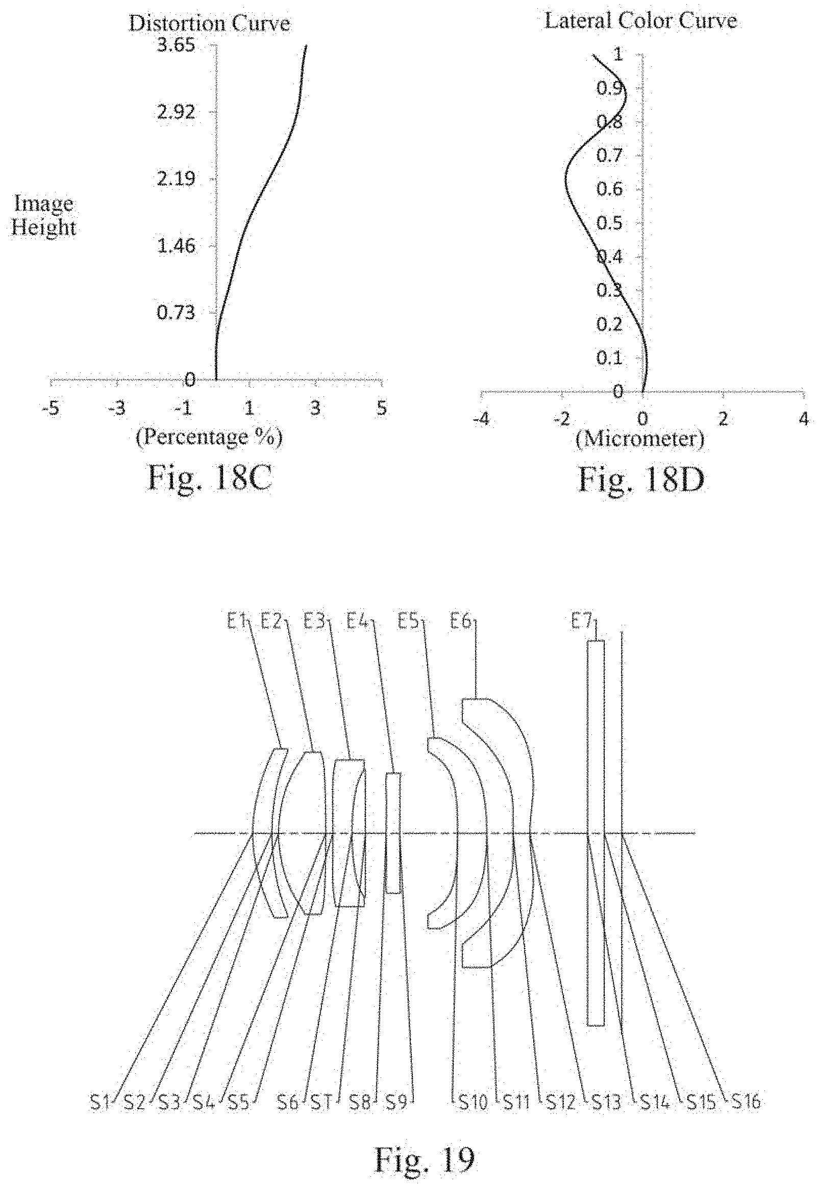
D00015

D00016

D00017


XML
uspto.report is an independent third-party trademark research tool that is not affiliated, endorsed, or sponsored by the United States Patent and Trademark Office (USPTO) or any other governmental organization. The information provided by uspto.report is based on publicly available data at the time of writing and is intended for informational purposes only.
While we strive to provide accurate and up-to-date information, we do not guarantee the accuracy, completeness, reliability, or suitability of the information displayed on this site. The use of this site is at your own risk. Any reliance you place on such information is therefore strictly at your own risk.
All official trademark data, including owner information, should be verified by visiting the official USPTO website at www.uspto.gov. This site is not intended to replace professional legal advice and should not be used as a substitute for consulting with a legal professional who is knowledgeable about trademark law.