Enzyme Quantification
Link; Darren R. ; et al.
U.S. patent application number 16/733132 was filed with the patent office on 2020-07-16 for enzyme quantification. The applicant listed for this patent is Bio-Rad Laboratories, Inc.. Invention is credited to Darren R. Link, Michael L. Samuels.
| Application Number | 20200225232 16/733132 |
| Document ID | / |
| Family ID | 47260399 |
| Filed Date | 2020-07-16 |


View All Diagrams
| United States Patent Application | 20200225232 |
| Kind Code | A1 |
| Link; Darren R. ; et al. | July 16, 2020 |
ENZYME QUANTIFICATION
Abstract
The invention generally relates to methods for quantifying an amount of enzyme molecules. Systems and methods of the invention are provided for measuring an amount of target by forming a plurality of fluid partitions, a subset of which include the target, performing an enzyme-catalyzed reaction in the subset, and detecting the number of partitions in the subset. The amount of target can be determined based on the detected number.
| Inventors: | Link; Darren R.; (Lexington, MA) ; Samuels; Michael L.; (Windham, NH) | ||||||||||
| Applicant: |
|
||||||||||
|---|---|---|---|---|---|---|---|---|---|---|---|
| Family ID: | 47260399 | ||||||||||
| Appl. No.: | 16/733132 | ||||||||||
| Filed: | January 2, 2020 |
Related U.S. Patent Documents
| Application Number | Filing Date | Patent Number | ||
|---|---|---|---|---|
| 13487030 | Jun 1, 2012 | 10533998 | ||
| 16733132 | ||||
| 12504764 | Jul 17, 2009 | |||
| 13487030 | ||||
| 61081930 | Jul 18, 2008 | |||
| 61492602 | Jun 2, 2011 | |||
| Current U.S. Class: | 1/1 |
| Current CPC Class: | G01N 33/542 20130101; B01J 2219/00702 20130101; C12Q 1/25 20130101; B01J 2219/0072 20130101; B01L 2300/0864 20130101; B01L 2300/0867 20130101; C12Q 1/6827 20130101; B01J 2219/00418 20130101; B01L 2400/0487 20130101; G01N 33/5008 20130101; B01F 5/0646 20130101; B01J 2219/00722 20130101; B01L 2300/0681 20130101; C12Q 1/6804 20130101; B01L 2300/0654 20130101; B01F 13/0062 20130101; C40B 40/04 20130101; B01J 2219/00585 20130101; B01J 2219/00664 20130101; B01J 2219/00576 20130101; B01L 7/52 20130101; C12Q 1/6818 20130101; B01L 2400/0415 20130101; G01N 33/582 20130101; C40B 60/10 20130101; G01N 21/6445 20130101; B01J 2219/00743 20130101; B01J 2219/00479 20130101; B01J 2219/00351 20130101; B01L 2200/027 20130101; B01L 2300/0636 20130101; G01N 33/573 20130101; B01F 5/0653 20130101; B01J 2219/0059 20130101; B01J 19/0046 20130101; B01J 2219/00592 20130101; B01J 2219/00599 20130101; B01J 2219/00286 20130101; B01L 2300/0645 20130101; C40B 50/08 20130101; G01N 21/6428 20130101; B01J 2219/00657 20130101; B01L 3/502761 20130101; G01N 2500/00 20130101; B01J 2219/0065 20130101; B01F 3/0807 20130101; B01J 2219/0074 20130101 |
| International Class: | G01N 33/573 20060101 G01N033/573; B01F 5/06 20060101 B01F005/06; B01J 19/00 20060101 B01J019/00; B01F 13/00 20060101 B01F013/00; B01L 3/00 20060101 B01L003/00; B01F 3/08 20060101 B01F003/08; C40B 40/04 20060101 C40B040/04; C40B 50/08 20060101 C40B050/08; C40B 60/10 20060101 C40B060/10; G01N 33/50 20060101 G01N033/50; C12Q 1/25 20060101 C12Q001/25; C12Q 1/6804 20060101 C12Q001/6804; C12Q 1/6818 20060101 C12Q001/6818; C12Q 1/6827 20060101 C12Q001/6827; G01N 33/542 20060101 G01N033/542; G01N 33/58 20060101 G01N033/58 |
Claims
1-20. (canceled)
21. A method for detecting a condition in a human, the method comprising: forming fluid partitions comprising components of a chemical reaction; conducting said chemical reaction; determining a distribution of at least one product of said chemical reaction; comparing the distribution to an expected distribution of said product; and identifying the presence of said condition if said distribution is statistically-significantly different than said expected distribution.
22. The method of claim 21, wherein said product is a protein.
23. The method of claim 22, wherein said protein is beta amyloid protein.
24. The method of claim 23, wherein said distribution is measured as an aggregate of said beta amyloid protein.
25. The method of claim 21, wherein at least one of the components of the chemical reaction comprises a detectable label that is acted on by the chemical reaction.
26. The method of claim 25, further comprising the step of identifying fluid partitions that contain released detectable label.
27. The method of claim 25, wherein the components comprise an enzyme and at least one substrate of the enzyme.
28. The method of claim 27, wherein the enzyme catalyzes a reaction that results in release of a detectable label from the substrate.
29. The method of claim 28, wherein the determining step comprises quantifying an amount of enzyme in the fluid partitions.
30. The method of claim 29, further comprising determining a number of enzyme molecules within each partition based upon signal strength of the detectable label.
31. The method of claim 25, wherein the determining step is based upon a localized concentration of the detectable label.
32. The method of claim 31, wherein the localized concentration is detected within a fluid partition.
33. The method of claim 21, wherein the fluid partitions are droplets.
34. The method of claim 33, wherein the droplets are surrounded by an immiscible carrier fluid.
Description
CROSS-REFERENCE TO RELATED APPLICATIONS
[0001] The present application is a continuation of U.S. patent application Ser. No. 13/487,030, filed Jun. 1, 2012, which is a continuation-in-part of U.S. patent application Ser. No. 12/504,764, filed Jul. 17, 2009, which claims priority to, and the benefit of, U.S. Provisional Application No. 61/081,930, filed Jul. 18, 2008, the contents of each of which are hereby incorporated by reference in their entirety. In addition, U.S. patent application Ser. No. 13/487,030 also claims priority to, and the benefit of, U.S. Provisional Patent Application No. 61/492,602, filed on Jun. 2, 2011, the contents of which are hereby incorporated by reference in their entirety.
FIELD OF INVENTION
[0002] The present invention generally relates to droplet libraries and to systems and methods for the formation of libraries of droplets. The present invention also relates to methods utilizing these droplet libraries in various biological, chemical, or diagnostic assays.
BACKGROUND
[0003] The manipulation of fluids to form fluid streams of desired configuration, discontinuous fluid streams, droplets, particles, dispersions, etc., for purposes of fluid delivery, product manufacture, analysis, and the like, is a relatively well-studied art. Microfluidic systems have been described in a variety of contexts, typically in the context of miniaturized laboratory (e.g., clinical) analysis. Other uses have been described as well. For example, International Patent Application Publication Nos. WO 01/89788; WO 2006/040551; WO 2006/040554; WO 2004/002627; WO 2008/063227; WO 2004/091763; WO 2005/021151; WO 2006/096571; WO 2007/089541; WO 2007/081385 and WO 2008/063227.
[0004] Precision manipulation of streams of fluids with microfluidic devices is revolutionizing many fluid-based technologies. Networks of small channels are a flexible platform for the precision manipulation of small amounts of fluids. However, virtually all microfluidic devices are based on flows of streams of fluids; this sets a limit on the smallest volume of reagent that can effectively be used because of the contaminating effects of diffusion and surface adsorption.
[0005] As the dimensions of small volumes shrink, diffusion becomes the dominant mechanism for mixing, leading to dispersion of reactants; moreover, surface adsorption of reactants, while small, can be highly detrimental when the concentrations are low and volumes are small. As a result, current microfluidic technologies cannot be reliably used for applications involving minute quantities of reagent; for example, bioassays on single cells or library searches involving single beads are not easily performed. An alternate approach that overcomes these limitations is the use of aqueous droplets in an immiscible carrier fluid; these provide a well-defined, encapsulated microenvironment that eliminates cross contamination or changes in concentration due to diffusion or surface interactions. Droplets provide the ideal microcapsule that can isolate reactive materials, cells, or small particles for further manipulation and study. However, essentially all enabling technology for microfluidic systems developed thus far has focused on single phase fluid flow and there are few equivalent active means to manipulate droplets requiring the development of droplet handling technology. While significant advances have been made in dynamics at the macro-or microfluidic scale, improved techniques and the results of these techniques are still needed. For example, as the scale of these reactors shrinks, contamination effects due to surface adsorption and diffusion limit the smallest quantities that can be used. Confinement of reagents in droplets in an immiscible carrier fluid overcomes these limitations, but demands new fluid-handling technology.
[0006] The present invention overcomes the current limitations in the field by providing precise, well-defined, droplet libraries which can be utilized alone, or within microfluidic channels and devices, to perform various biological and chemical assays efficiently and effectively, especially at high speeds.
SUMMARY
[0007] This invention provides methods to identify and quantify the presence, type, and amount of reactants and products of chemical reactions. The invention takes advantage of the ability to form discrete droplets that contain the components of a chemical reaction. Because measurements can be performed on individual droplets and collections of individual droplet, it is possible to identify and quantify chemical reaction components in the droplets according to methods described herein. Methods of the invention are useful to detect and/or quantify any component of a chemical reaction. In one preferred embodiment, enzyme molecules are quantified based on their activity inside individual droplets. In order to identify and quantitate enzyme activity, droplets are identified as "negative" and/or "positive" droplets for the reaction catalyzed by the target enzyme, and the number of enzyme molecules within positive droplets (e.g., based on the quantized signal strength) is determined. Digital counting of enzyme molecules provides an extremely wide dynamic range of detection, with a lower limit of detection dependent on the number of molecules available to count and the total number of droplets read (e.g. 1 in 10.sup.7, in one hour using a droplet flow rate of 10.sup.7 per hour) and the upper limit for single molecule counting determined by the number of droplets but also includes a further range where multiple or average numbers of molecules are present in droplets.
[0008] In general, the invention involves incorporating components of a chemical reaction in a droplet and allowing the chemical reaction to occur in the droplet. One or more of the components of the reaction is detectably labeled (e.g., with a reporter molecule) such that label is detectable as a result of the reaction (e.g., release of a reporter). Detection and quantification of the label allows detection and quantification of the reaction components. The reporter moiety may be any detectable moiety that can be used as an indicator of reaction components (e.g., enzyme activity). Any reporter system known in the art may be used with methods of the invention. In certain embodiments, the reporter moiety is a fluorescent moiety.
[0009] In a preferred embodiment, a reporter is attached to one or more substrate(s) of a chemical reaction in a droplet, which label is released upon enzymatic catalysis. The number of droplets containing quantified enzyme molecules are then determined based upon the presence and/or signal strength of the reporter. Reporter (and therefore enzyme) can be quantified based upon these measurements as well. Methods of the invention involve forming a sample droplet. Any technique known in the art for forming sample droplets may be used with methods of the invention. An exemplary method involves flowing a stream of sample fluid so that the sample stream intersects one or more opposing streams of flowing carrier fluid. The carrier fluid is immiscible with the sample fluid. Intersection of the sample fluid with the two opposing streams of flowing carrier fluid results in partitioning of the sample fluid into individual sample droplets. The carrier fluid may be any fluid that is immiscible with the sample fluid. An exemplary carrier fluid is oil, which may in some cases be fluorinated. In certain embodiments, the carrier fluid includes a surfactant, such as a fluorosurfactant.
[0010] In some aspects, the invention provides methods for digital distribution assays that allow, for example, for detection of a physiological condition in a human. Detectable physiological conditions include conditions associated with aggregation of proteins or other targets. Methods include forming fluid partitions that include components of a detectable chemical reaction and conducting the reaction. A distribution of at least one of the components is determined based on detecting the detectable reaction. A statistically expected distribution can be computed and compared to the determined distribution or comparisons of distributions from known or typical samples. Based on these comparisons, the presence and/or the severity of the potential condition can be determined. In certain embodiments, the condition involves protein aggregation. The protein can be a protein from a sample from a patient. In some embodiments, methods assay for Alzheimer's disease, Parkinson's disease, Huntington's disease, Type II diabeties mellitus, prion-associated diseases, or other conditions.
[0011] Another droplet formation method includes merging at least two droplets, in which each droplet includes different material. Another droplet formation method includes forming a droplet from a sample, and contacting the droplet with a fluid stream, in which a portion of the fluid stream integrates with the droplet to form a droplet. An electric field may be applied to the droplet and the fluid stream. The electric field assists in rupturing the interface separating the two fluids. In particular embodiments, the electric field is a high-frequency electric field.
[0012] Methods of the invention may be conducted in microfluidic channels. As such, in certain embodiments, methods of the invention may further involve flowing the droplet channels and under microfluidic control.
BRIEF DESCRIPTION OF THE DRAWINGS
[0013] Non-limiting embodiments of the present invention will be described by way of example with reference to the accompanying drawings, which are schematic and are not intended to be drawn to scale. In the drawings, each identical or nearly identical component illustrated is typically represented by a single numeral. For the purposes of clarity, not every component is labeled in every drawing, nor is every component of each embodiment of the invention shown where illustration is not necessary to allow those of ordinary skill in the art to understand the invention. In the drawings:
[0014] FIG. 1 is an schematic illustrating the interacting modules of a microfluidic device of the present invention.
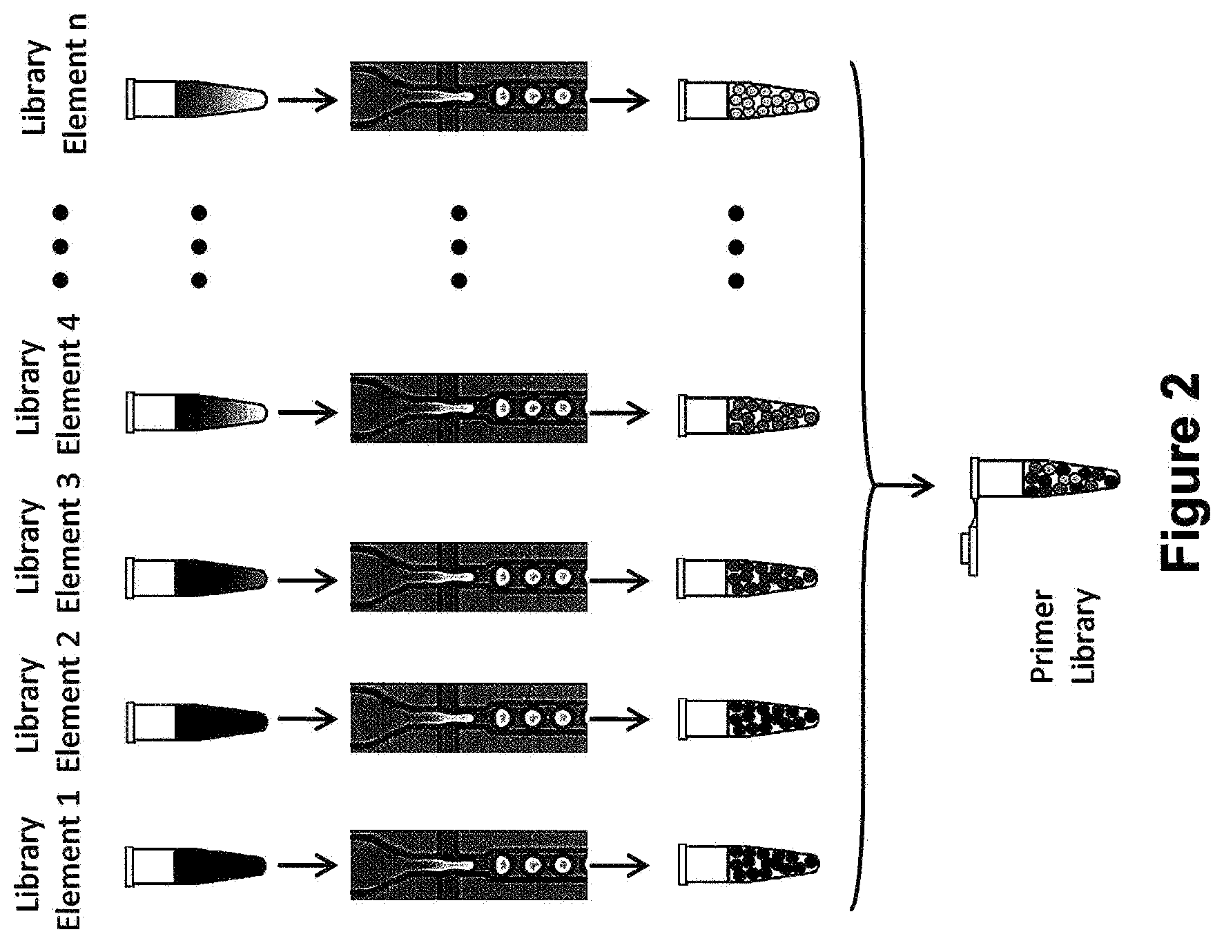
[0015] FIG. 2 is a schematic illustrating a one emulsion library.
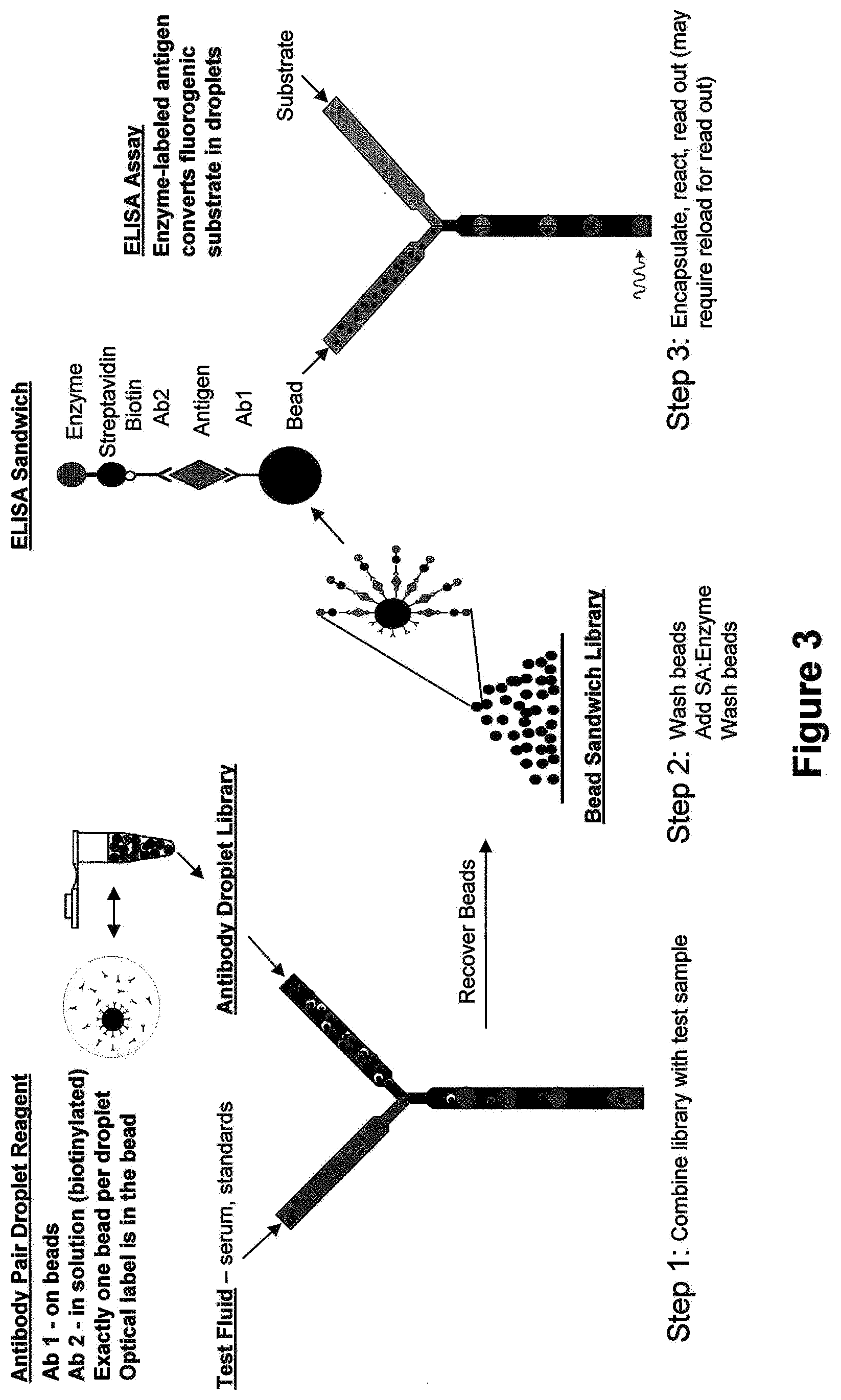
[0016] FIG. 3 is a schematic illustrating an antibody pair library for ELISA Application.
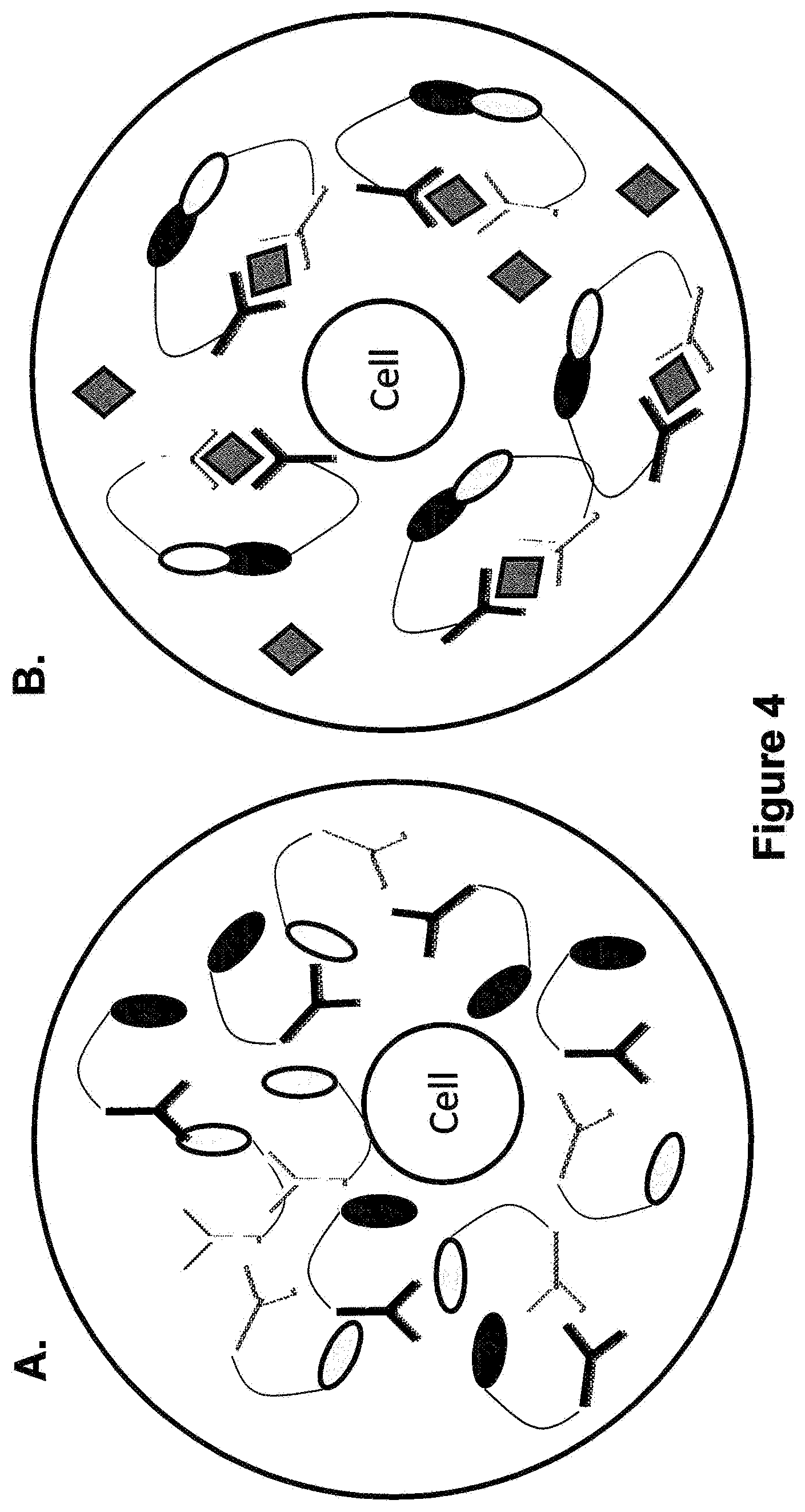
[0017] FIG. 4 Panel A is a schematic illustrating that the cell in the Protein-Fragment Complementation Assay is not secreting any antigen hence the fluorogenic substrate is not converted into a fluorescent product. Panel B is a schematic showing the conversion to a fluorescent product.
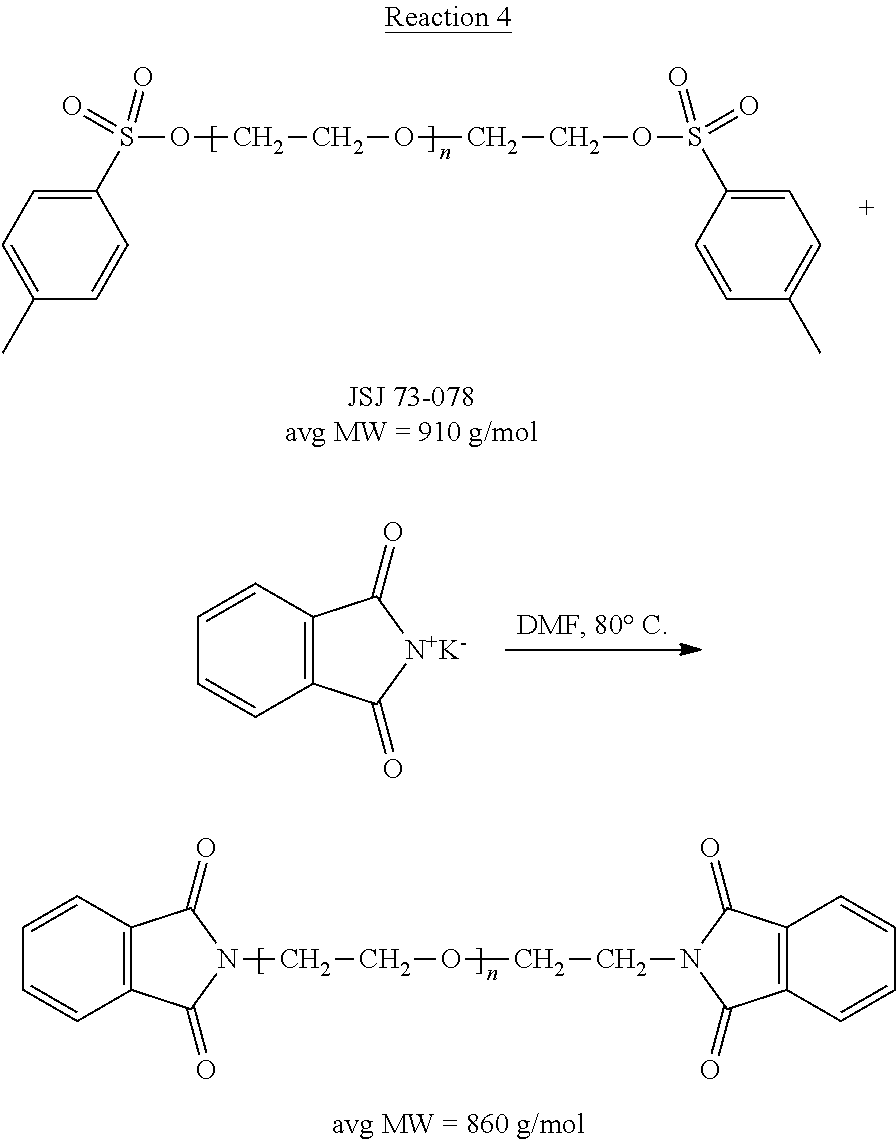
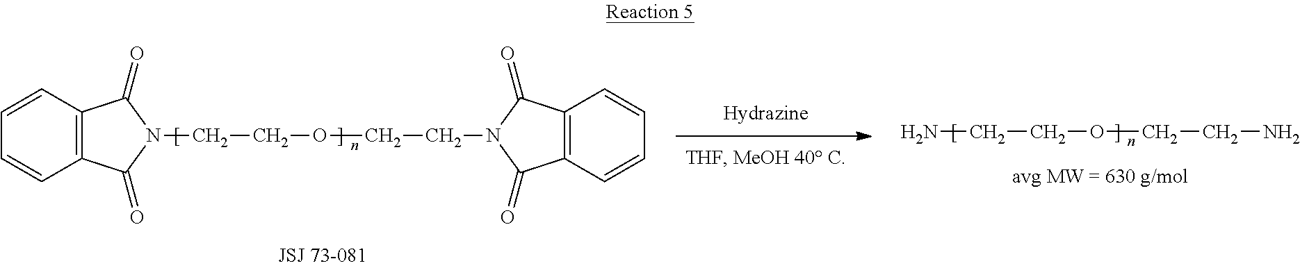
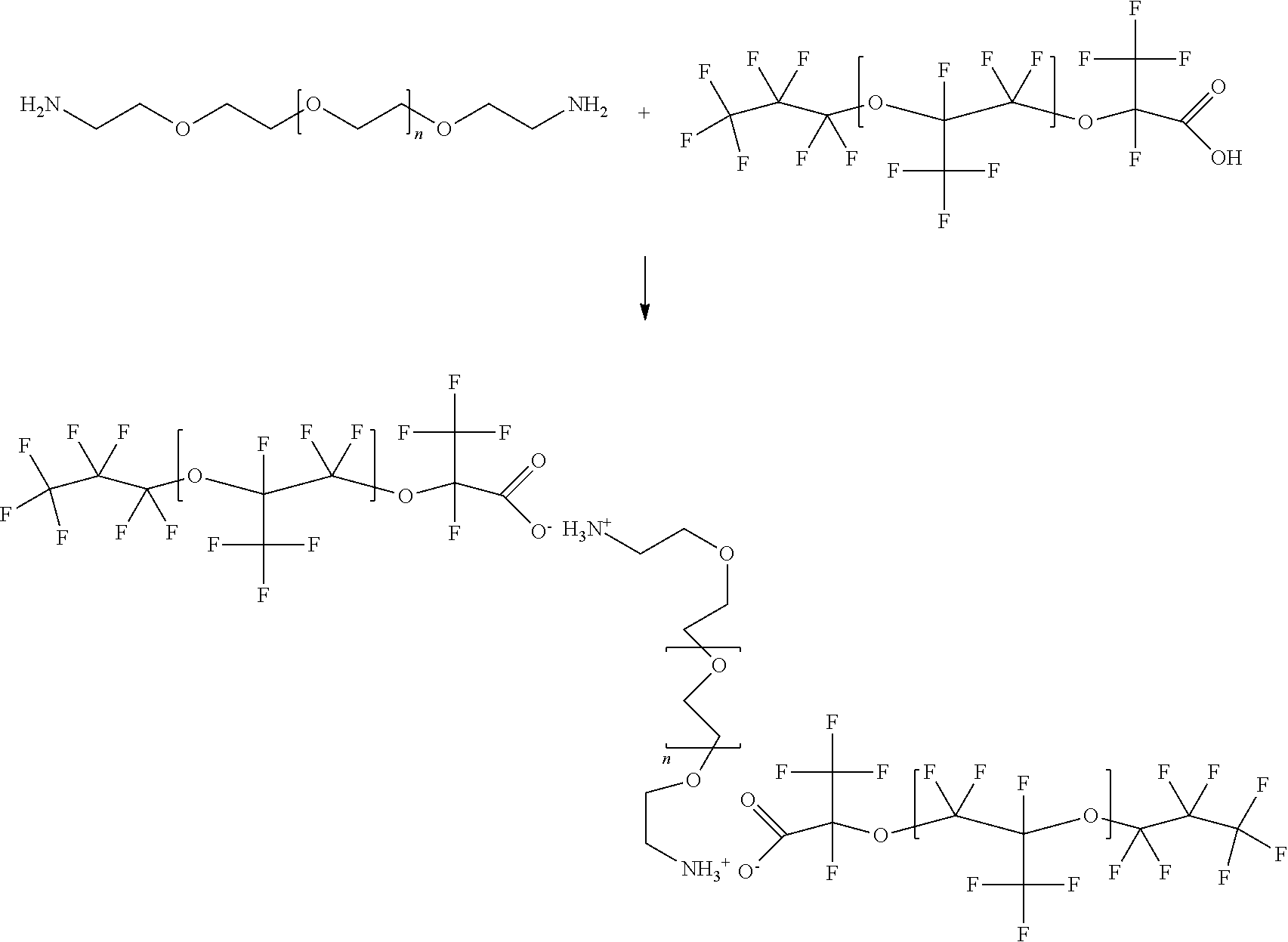
[0018] FIG. 5 Panel A is a photograph showing droplets containing Ammonium Carboxylate Salt of Krytox 157 FSH 2 Wt % in FC 3283 without PEG amine salt. Panel B is a photograph showing droplets containing PEG 600 Diammonium Carboxylate Salt of Krytox 157 FSH at 4.0% by volume.
[0019] FIG. 6 is a schematic illustrating a primer library generation.
[0020] FIG. 7 is a schematic illustrating enzyme amplified flow cytometry.
[0021] FIGS. 8A-8G show droplet formation and detection of reaction positive droplets.
[0022] FIGS. 9A-9D show readouts of time traces at different enzyme concentrations. Time traces show digital reactions in droplets at low enzyme concentrations.
[0023] FIGS. 10A-10D show readouts of histograms. Increasing enzyme concentrations shifts the distribution from quantized to average regime.
[0024] FIGS. 11A and 11B illustrate concentration determination using digital droplet data. Digital counting measurement of enzyme concentration matches known starting amount.
[0025] FIG. 12 is a schematic showing sandwich formation for digital droplet ELISA.
[0026] FIGS. 13A-13D illustrates different digital droplet ELISA readout counting modes.
[0027] FIGS. 14A and 14B show embodiments for multiplexing digital assay.
[0028] FIGS. 15A and 15B show fluorescent polarization as another mode for readout.
[0029] FIGS. 16A and 16B illustrate localized florescence as another mode for readout.
[0030] FIG. 17 is illustrates a digital competitive allele specific enzyme (CASE) assay.
[0031] FIGS. 18A-18C show multiplexing embodiments.
[0032] FIGS. 19A and 19B show a workflow for a localized fluorescence binding assay.
[0033] FIG. 20 shows monocyte detection according to certain embodiments.
[0034] FIGS. 21A-21C illustrate single droplet traces including optical labels.
[0035] FIGS. 22A-22C give single droplet traces with a scatter plot and histogram.
[0036] FIGS. 23A-23C diagram adjusting a dynamic range of a localized fluorescence assay.
[0037] FIG. 24 is a drawing showing a device for droplet formation.
[0038] FIG. 25 is a drawing showing a device for droplet formation.
[0039] FIG. 26 is a diagram of results of a digital distribution assay.
DETAILED DESCRIPTION
[0040] Droplet Libraries
[0041] Droplet libraries are useful to perform large numbers of assays while consuming only limited amounts of reagents. A "droplet," as used herein, is an isolated portion of a first fluid that completely surrounded by a second fluid. In some cases, the droplets may be spherical or substantially spherical; however, in other cases, the droplets may be non-spherical, for example, the droplets may have the appearance of "blobs" or other irregular shapes, for instance, depending on the external environment. As used herein, a first entity is "surrounded" by a second entity if a closed loop can be drawn or idealized around the first entity through only the second entity.
[0042] In general, a droplet library is made up of a number of library elements that are pooled together in a single collection. Libraries may vary in complexity from a single library element to 10.sup.15 library elements or more. Each library element is one or more given components at a fixed concentration. The element may be, but is not limited to, cells, virus, bacteria, yeast, beads, amino acids, proteins, polypeptides, nucleic acids, polynucleotides or small molecule chemical compounds. The element may contain an identifier such as a label. The terms "droplet library" or "droplet libraries" are also referred to herein as an "emulsion library" or "emulsion libraries." These terms are used interchangeably throughout the specification.
[0043] A cell library element can include, but is not limited to, hybridomas, B-cells, primary cells, cultured cell lines, cancer cells, stem cells, or any other cell type. Cellular library elements are prepared by encapsulating a number of cells from one to tens of thousands in individual droplets. The number of cells encapsulated is usually given by Poisson statistics from the number density of cells and volume of the droplet. However, in some cases the number deviates from Poisson statistics as described in Edd et al., "Controlled encapsulation of single-cells into monodisperse picolitre drops" Lab Chip, 8(8):1262-1264, 2008. The discreet nature of cells allows for libraries to be prepared in mass with a plurality of cellular variants all present in a single starting media and then that media is broken up into individual droplet capsules that contain at most one cell. These individual droplets capsules are then combined or pooled to form a library consisting of unique library elements. Cell division subsequent to, or in some embodiments following, encapsulation produces a clonal library element.
[0044] A bead based library element contains one or more beads, of a given type and may also contain other reagents, such as antibodies, enzymes or other proteins. In the case where all library elements contain different types of beads, but the same surrounding media, the library elements can all be prepared from a single starting fluid or have a variety of starting fluids. In the case of cellular libraries prepared in mass from a collection of variants, such as genomically modified, yeast or bacteria cells, the library elements will be prepared from a variety of starting fluids.
[0045] Often it is desirable to have exactly one cell per droplet with only a few droplets containing more than one cell when starting with a plurality of cells or yeast or bacteria, engineered to produce variants on a protein. In some cases, variations from Poisson statistics can be achieved to provide an enhanced loading of droplets such that there are more droplets with exactly one cell per droplet and few exceptions of empty droplets or droplets containing more than one cell.
[0046] Examples of droplet libraries are collections of droplets that have different contents, ranging from beads, cells, small molecules, DNA, primers, antibodies. The droplets range in size from roughly 0.5 micron to 500 micron in diameter, which corresponds to about 1 pico liter to 1 nano liter. However, droplets can be as small as 5 microns and as large as 500 microns. Preferably, the droplets are at less than 100 microns, about 1 micron to about 100 microns in diameter. The most preferred size is about 20 to 40 microns in diameter (10 to 100 picoliters). The preferred properties examined of droplet libraries include osmotic pressure balance, uniform size, and size ranges.
[0047] The droplets comprised within the droplet library provided by the instant invention are uniform in size. That is, the diameter of any droplet within the library will vary less than 5%, 4%, 3%, 2%, 1% or 0.5% when compared to the diameter of other droplets within the same library. The uniform size of the droplets in the library is critical to maintain the stability and integrity of the droplets and is also essential for the subsequent use of the droplets within the library for the various biological and chemical assays described herein.
[0048] The droplets comprised within the emulsion libraries of the present invention are contained within an immiscible fluorocarbon oil comprising at least one fluorosurfactant. In some embodiments, the fluorosurfactant comprised within immiscible fluorocarbon oil is a block copolymer consisting of one or more perfluorinated polyether (PFPE) blocks and one or more polyethylene glycol (PEG) blocks. In other embodiments, the fluorosurfactant is a triblock copolymer consisting of a PEG center block covalently bound to two PFPE blocks by amide linking groups. The presence of the fluorosurfactant (similar to uniform size of the droplets in the library) is critical to maintain the stability and integrity of the droplets and is also essential for the subsequent use of the droplets within the library for the various biological and chemical assays described herein. Fluids (e.g., aqueous fluids, immiscible oils, etc.) and other surfactants that can be utilized in the droplet libraries of the present invention are described in greater detail herein.
[0049] The droplet libraries of the present invention are very stable and are capable of long-term storage. The droplet libraries are determined to be stable if the droplets comprised within the libraries maintain their structural integrity, that is the droplets do not rupture and elements do not diffuse from the droplets. The droplets libraries are also determined to be stable if the droplets comprised within the libraries do not coalesce spontaneously (without additional energy input, such as electrical fields described in detail herein). Stability can be measured at any temperature. For example, the droplets are very stable and are capable of long-term storage at any temperature; for example, e.g., -70.degree. C., 0.degree. C., 4.degree. C., 37.degree. C., room temperature, 75.degree. C. and 95.degree. C. Specifically, the droplet libraries of the present invention are stable for at least 30 days. More preferably, the droplets are stable for at least 60 days. Most preferably, the droplets are stable for at least 90 days.
[0050] The present invention provides an emulsion library comprising a plurality of aqueous droplets within an immiscible fluorocarbon oil comprising at least one fluorosurfactant, wherein each droplet is uniform in size and comprises the same aqueous fluid and comprises a different library element. The present invention also provides a method for forming the emulsion library comprising providing a single aqueous fluid comprising different library elements, encapsulating each library element into an aqueous droplet within an immiscible fluorocarbon oil comprising at least one fluorosurfactant, wherein each droplet is uniform in size and comprises the same aqueous fluid and comprises a different library element, and pooling the aqueous droplets within an immiscible fluorocarbon oil comprising at least one fluorosurfactant, thereby forming an emulsion library.
[0051] For example, in one type of emulsion library, all different types of elements (e.g., cells or beads), are pooled in a single source contained in the same medium. After the initial pooling, the cells or beads are then encapsulated in droplets to generate a library of droplets wherein each droplet with a different type of bead or cell is a different library element. The dilution of the initial solution enables the encapsulation process. In some embodiments, the droplets formed will either contain a single cell or bead or will not contain anything, i.e., be empty. In other embodiments, the droplets formed will contain multiple copies of a library element. The cells or beads being encapsulated are generally variants on the same type of cell or bead. In one example, the cells can comprise cancer cells of a tissue biopsy, and each cell type is encapsulated to be screened for genomic data or against different drug therapies. Another example is that 10.sup.11 or 10.sup.15 different type of bacteria; each having a different plasmid spliced therein, are encapsulated. One example is a bacterial library where each library element grows into a clonal population that secretes a variant on an enzyme.
[0052] In another example, the emulsion library comprises a plurality of aqueous droplets within an immiscible fluorocarbon oil, wherein a single molecule is encapsulated, such that there is a single molecule contained within a droplet for every 20-60 droplets produced (e.g., 20, 25, 30, 35, 40, 45, 50, 55, 60 droplets, or any integer in between). Single molecules are encapsulated by diluting the solution containing the molecules to such a low concentration that the encapsulation of single molecules is enabled. In one specific example, a LacZ plasmid DNA was encapsulated at a concentration of 20 fM after two hours of incubation such that there was about one gene in 40 droplets, where 10 .mu.m droplets were made at 10 kHz per second. Formation of these libraries rely on limiting dilutions.
[0053] The present invention also provides an emulsion library comprising at least a first aqueous droplet and at least a second aqueous droplet within a fluorocarbon oil comprising at least one fluorosurfactant, wherein the at least first and the at least second droplets are uniform in size and comprise a different aqueous fluid and a different library element. The present invention also provides a method for forming the emulsion library comprising providing at least a first aqueous fluid comprising at least a first library of elements, providing at least a second aqueous fluid comprising at least a second library of elements, encapsulating each element of said at least first library into at least a first aqueous droplet within an immiscible fluorocarbon oil comprising at least one fluorosurfactant, encapsulating each element of said at least second library into at least a second aqueous droplet within an immiscible fluorocarbon oil comprising at least one fluorosurfactant, wherein the at least first and the at least second droplets are uniform in size and comprise a different aqueous fluid and a different library element, and pooling the at least first aqueous droplet and the at least second aqueous droplet within an immiscible fluorocarbon oil comprising at least one fluorosurfactant thereby forming an emulsion library.
[0054] For example, in one type of emulsion library, there are library elements that have different particles, i.e., cells or beads in a different medium and are encapsulated prior to pooling. As exemplified in FIG. 2, a specified number of library of elements, i.e., n number of different cells or beads, are contained within different mediums. Each of the library elements are separately emulsified and pooled, at which point each of the n number of pooled different library elements are combined and pooled into a single pool. The resultant pool contains a plurality of water-in-oil emulsion droplets each containing a different type of particle.
[0055] In some embodiments, the droplets formed will either contain a single library element or will not contain anything, i.e., be empty. In other embodiments, the droplets formed will contain multiple copies of a library element. The contents of the beads follow a Poisson distribution, where there is a discrete probability distribution that expresses the probability of a number of events occurring in a fixed period of time if these events occur with a known average rate and independently of the time since the last event. The oils and surfactants used to create the libraries prevents the exchange of the contents of the library between droplets.
[0056] Examples of assays that utilize these emulsion libraries are ELISA assays. The present invention provides another emulsion library comprising a plurality of aqueous droplets within an immiscible fluorocarbon oil comprising at least one fluorosurfactant, wherein each droplet is uniform in size and comprises at least a first antibody, and a single element linked to at least a second antibody, wherein said first and second antibodies are different. In one example, each library element comprises a different bead, wherein each bead is attached to a number of antibodies and the bead is encapsulated within a droplet that contains a different antibody in solution. These antibodies can then be allowed to form "ELISA sandwiches," which can be washed and prepared for a ELISA assay. Further, these contents of the droplets can be altered to be specific for the antibody contained therein to maximize the results of the assay. A specific example of an ELSA assay is shown in Example 5 and in FIG. 3.
[0057] The present invention also provides another emulsion library comprising a plurality of aqueous droplets within an immiscible fluorocarbon oil comprising at least one fluorosurfactant, wherein each droplet is uniform in size and comprises at least a first element linked to at least a first antibody, and at least a second element linked to at least a second antibody, wherein said first and second antibodies are different. In one example of a Protein-Fragment Complementation Assay (PCA), library droplets are prepared to contain a mixture of two different antibodies. Wherein the two antibodies bind with strong affinity to different epitopes of the antigen molecule that is to be detected. Detection is achieved by tethering protein fragments to the each of the antibodies such that when held in proximity the two fragments create an active enzyme capable of turning over a fluorogenic substrate, only in the presence of the antigen. For example, as shown in FIG. 4 Panel A, the cell is not secreting any antigen hence the fluorogenic substrate is not converted into a fluorescent product. By contrast, in Panel B, the cell is secreting the antigen. Hence when the antibodies bind to it the two protein fragments are held in close enough proximity to form an active enzyme. The intensity of the fluorescence signal generated from these sandwiches is indicative of the antigen concentration in the droplet.
[0058] In another example, of the emulsion library, the library begins with a certain number of library elements, which may contain proteins, enzymes, small molecules and PCR primers, among other reagents. However, there is no Poisson distribution in these droplet libraries, Rather, each library is added to a droplet in a specific concentration. In these droplet libraries, there are a large number of the reagent contained within the droplets. With small molecule chemical compounds, each library element can be the same small molecule chemical compound at different concentrations or be completely different small molecule chemical compound per element. When encapsulating PCR primers there are any number of a single type of primer pairs contained within each droplet.
[0059] Labels can be used for identification of the library elements of the various types of droplet libraries. Libraries can be labeled for unique identification of each library element by any means known in the art. The label can be an optical label, an enzymatic label or a radioactive label. The label can be any detectable label, e.g., a protein, a DNA tag, a dye, a quantum dot or a radio frequency identification tag, or combinations thereof. Preferably the label is an optical label. The label can be detected by any means known in the art. Preferably, the label is detected by fluorescence polarization, fluorescence intensity, fluorescence lifetime, fluorescence energy transfer, pH, ionic content, temperature or combinations thereof. Various labels and means for detection are described in greater detail herein.
[0060] Specifically, after a label is added to each of the various library elements, the elements are then encapsulated and each of the droplets contains a unique label so that the library elements may be identified. In one example, by using various combinations of labels and detection methods, it is possible to use two different colors with different intensities or to use a single color at a different intensity and different florescence anisotropy.
[0061] Optical labels are also utilized in quality control in order to ensure that the droplet libraries are well controlled, and that equal number of each library elements are contained within uniform volumes in each droplet library. After 120 minutes of mixing, using 8-labels in a 96-member library, the average number of droplets is 13,883 for each of the library elements. As Table 1 shows below, there is very little variation between the number of droplets for each library element, i.e., between -0.8% to +1.1%. The slight variation in the number of droplets allows the pooled droplet libraries to be used in any number of assays.
TABLE-US-00001 TABLE 1 Element G1 G2 G3 G4 G5 G6 G7 G8 # drops 13913 13898 14036 13898 13834 13927 13788 13769 % variation +0.2% 0% +1.1% 0% -0.4% +0.3% -0.7% -0.8%
[0062] In some quality control examples, 384-member libraries were prepared with eight optical labels; typically 5 to 20 micro-liters of each library element are emulsified into approximately 10 picoliter volume droplets so there are about 1 million droplets of each library element and 384 million droplets in the library.
[0063] The eight optical labels are a dye at concentrations that increase by a factor of c (where c ranges from about 1.2 to 1.4) from one optical label to the next so that the nth optical label has (c)(n-1) the dye concentration of the lowest concentration. Optical labels are used with concentrations between 10 nM and1 uM. Typically, the range of optical label concentrations for one series of labels is 1 order of magnitude (e.g., 10 nM to 100 nM with a multiplier of 1.43 for each increasing label concentration). A larger range of droplet label concentrations can also be used. Further, multiplexed two-color labels can be used as well.
[0064] Plates are prepared with 384 separate library elements in separate wells of the 384-well plates; 8 of which have optical labels. The library elements are made into droplets, collected in a vial, (also known as a creaming tower) and the collection is mixed on the mixer for several hours. The mixer works by flipping the vial over about once every 30 seconds and then allowing the droplets to rise. Multiple plates can be emulsified and pooled or collected sequentially into the same vial.
[0065] A small fraction of the droplets are taken out of the vial to verify 1) that the droplets are present in the correct predetermined ratio and 2) that the droplets are of uniform size. Typically, 1,000 to 10,000 droplets of each library element (0.384 to 3.84 million QC-droplets) are removed from the vial through a PEEK line in the center opening in the vial cap by positive displacement with a drive oil infused through the side opening in vial cap. The PEEK line takes the droplets into a port on a microfluidic chip at a rate of several thousand droplets/second; for 10 picoliter droplets at a rate of 3000 droplets/s corresponds to a typical infusion rate of roughly 110 micro-liters/hr. Once on chip the droplets are spaced out by adding oil before they are imaged and pass one droplet at a time through a laser excitation spot. Maximum fluorescence intensity data from individual droplets is collected for all of the QC-droplets and histograms are built to show the number of droplets within a given fluorescence intensity range. As expected, if eight of the library elements have optical labels, then there are eight peaks in the histograms. The increasing concentration factor c=1.38 results in uniformly separated peaks across one decade when plotted on a log scale. The relative number of droplets in each peak is used as a quality metric to validate that the libraries were prepared with the expected relative representation. In this example, the percent variation is determined to be only 2.7% demonstrating that all library elements have uniform representation.
[0066] Image analysis can be utilized to determine and monitor osmotic pressure within the droplets. Osmotic pressure (e.g., two member library prepared with a small difference in buffer concentration) can effect droplets. Specifically, droplets with a lower salt concentration shrink over time and droplets with higher salt concentration grow over time, until uniform salt concentrations are achieved. Thus it.
[0067] Image analysis can also be utilizes for quality control of the library reformatting process. After the various library elements are generated, pooled and mixed, optical labels can be used to verify uniform representation of all library elements. Additionally, image analysis is used to verify uniform volume for all droplets.
[0068] Further, image analysis can be used for shelf life testing by quantifying the materials performance. Droplets are stored in vials under a variety of conditions to test droplets stability against droplet-droplet coalescence events. Conditions tested include temperature, vibration, presence of air in vials, surfactant type, and surfactant concentration. A Quality Score of percent coalescence is calculated by image analysis. Shelf-life for the droplet libraries of the present invention exceed 90 days.
[0069] Microfluidic Systems
[0070] Reagents can be reformatted as droplet libraries utilizing automated devices. Specifically, the library elements can be placed onto plates containing any number of wells, i.e. 96, 384, etc. The plates can then be placed in an Automated Droplet Library Production machine (or other such automated device known in the art), which forms the droplets and puts them into a vial or other such container, containing the ready to use droplet library. In general, the process aspirates each of the library elements from the well plates through tubing connected to a microfluidic device (described in greater detail herein) which can be used to form the droplets. The tubing that aspirates the library elements can be rinsed at a wash station and then the process can be repeated for the next library element.
[0071] A collection vial can be used to contain the droplets made using the Automated Droplet Library Production. In one example, the collection vial has two holes, a first hole in the center of the vial cap and a second hole part way to the edge of the vial cap. The vial is first filled with oil through the second hole to purge air out first hole, the emulsion is then introduced to the vial through the first hole, typically this is done sequentially one library element at a time at low volume fraction, and oil is displaced and goes out through the second hole. The collected droplets can be stored in the vial for periods of time in excess of 3 months. To remove the emulsion for use or to make smaller aliquots, oil is introduced through the second opening to displace the emulsion and drive out the first opening.
[0072] The droplet libraries of the present invention are preferably formed by utilizing microfluidic devices and are preferably utilized to perform various biological and chemical assays on microfluidic devices, as described in detail herein. The present invention also provides embedded microfluidic nozzles. In order to create a monodisperse (<1.5% polydispersity) emulsion directly from a library well, a nozzle can be formed directly into the fitting used to connect the storage well/reservoir (e.g. syringe) to a syringe tip (e.g. capillary tubing). Examples of suitable nozzles to create the droplet libraries of the instant invention are described in WO 2007/081385 and WO 2008/063227.
[0073] Since the flow is three dimensional, under this design surface wetting effects are minimized. The nozzle can be made from one or two oil lines providing constant flow of oil into the nozzle, a connection to the capillary tubing, and a connection to the storage well/reservoir (e.g. syringe). The high resolution part of the nozzle can be made out of a small bore tubing or a small, simple part molded or stamped from an appropriate material (TEFLON, plastic, metal, etc). If necessary, the nozzle itself could be formed into the tip of the ferrule using post mold processing such as laser ablation or drilling.
[0074] This nozzle design eliminates the surface wetting issues surrounding the quasi-2D flow associated with typical microfluidic nozzles made using soft lithography or other standard microfluidic chip manufacturing techniques. This is because the nozzle design is fully 3-dimensional, resulting is a complete isolation of the nozzle section from the continuous aqueous phase. This same design can also be used for generation of emulsions required for immediate use, where the aqueous line would be attached directly to a syringe and the outlet of the nozzle would be used to transport the emulsion to the point of use (e.g. into a microfluidic PCR chip, delay line, etc).
[0075] In another embodiment, the present invention provides compositions and methods to directly emulsify library elements from standard library storage geometries (e.g. 96 well plates, etc). In order to create a monodisperse emulsion from fluids contained in a library well plate, this invention would include microfluidic based nozzles manufactured simultaneously with an appropriately designed fluidic interconnect or well.
[0076] Specifically, the microfluidic devices and methods described herein are based on the creation and electrical manipulation of aqueous phase droplets (e.g., droplet libraries) completely encapsulated by an inert immiscible oil stream. This combination enables precise droplet generation, highly efficient, electrically addressable, droplet coalescence, and controllable, electrically addressable single droplet sorting. The microfluidic devices include one or more channels and modules. A schematic illustrating one example of interacting modules of a microfluidic substrate is shown in FIG. 1. The integration of these modules is an essential enabling technology for a droplet based, high-throughput microfluidic reactor system and provides an ideal system for utilizing the droplet libraries provided herein for numerous biological, chemical, or diagnostic applications.
[0077] Substrates
[0078] The microfluidic device of the present invention includes one or more analysis units. An "analysis unit" is a microsubstrate, e.g., a microchip. The terms microsubstrate, substrate, microchip, and chip are used interchangeably herein. The analysis unit includes at least one inlet channel, at least one main channel and at least one inlet module. The analysis unit can further include at least one coalescence module. at least one detection module and one or more sorting modules. The sorting module can be in fluid communication with branch channels which are in fluid communication with one or more outlet modules (collection module or waste module). For sorting applications, at least one detection module cooperates with at least one sorting module to divert flow via a detector-originated signal. It shall be appreciated that the "modules" and "channels" are in fluid communication with each other and therefore may overlap; i.e., there may be no clear boundary where a module or channel begins or ends. A plurality of analysis units of the invention may be combined in one device. The dimensions of the substrate are those of typical microchips, ranging between about 0.5 cm to about 15 cm per side and about 1 micron to about 1 cm in thickness. The analysis unit and specific modules are described in further detail in WO 2006/040551; WO 2006/040554; WO 2004/002627; WO 2004/091763; WO 2005/021151; WO 2006/096571; WO 2007/089541; WO 2007/081385 and WO 2008/063227. A variety of materials and methods can be used to form any of the described components of the systems and devices of the invention. For example, various components of the invention can be formed from solid materials, in which the channels can be formed via molding, micromachining, film deposition processes such as spin coating and chemical vapor deposition, laser fabrication, photolithographic techniques, etching methods including wet chemical or plasma processes, and the like. See, for example, Angell, et al., Scientific American, 248:44-55, 1983. At least a portion of the fluidic system can be formed of silicone by molding a silicone chip. Technologies for precise and efficient formation of various fluidic systems and devices of the invention from silicone are known. Various components of the systems and devices of the invention can also be formed of a polymer, for example, an elastomeric polymer such as polydimethylsiloxane ("PDMS"), polytetrafluoroethylene ("PTFE") or TEFLON, or the like.
[0079] Silicone polymers are preferred, for example, the silicone elastomer polydimethylsiloxane. Non-limiting examples of PDMS polymers include those sold under the trademark Sylgard by Dow Chemical Co., Midland, Mich., and particularly Sylgard 182, Sylgard 184, and Sylgard 186. Silicone polymers including PDMS have several beneficial properties simplifying formation of the microfluidic structures of the invention. For instance, such materials are inexpensive, readily available, and can be solidified from a prepolymeric liquid via curing with heat. For example, PDMSs are typically curable by exposure of the prepolymeric liquid to temperatures of about, for example, about 65 .degree. C. to about 75 .degree. C. for exposure times of, for example, about an hour. Also, silicone polymers, such as PDMS, can be elastomeric and thus may be useful for forming very small features with relatively high aspect ratios, necessary in certain embodiments of the invention. Flexible (e.g., elastomeric) molds or masters can be advantageous in this regard.
[0080] One advantage of forming structures such as microfluidic structures of the invention from silicone polymers, such as PDMS, is the ability of such polymers to be oxidized, for example by exposure to an oxygen-containing plasma such as an air plasma, so that the oxidized structures contain, at their surface, chemical groups capable of cross-linking to other oxidized silicone polymer surfaces or to the oxidized surfaces of a variety of other polymeric and non-polymeric materials. Thus, components can be formed and then oxidized and essentially irreversibly sealed to other silicone polymer surfaces, or to the surfaces of other substrates reactive with the oxidized silicone polymer surfaces, without the need for separate adhesives or other sealing means. In most cases, sealing can be completed simply by contacting an oxidized silicone surface to another surface without the need to apply auxiliary pressure to form the seal. That is, the pre-oxidized silicone surface acts as a contact adhesive against suitable mating surfaces. Specifically, in addition to being irreversibly sealable to itself, oxidized silicone such as oxidized PDMS can also be sealed irreversibly to a range of oxidized materials other than itself including, for example, glass, silicon, silicon oxide, quartz, silicon nitride, polyethylene, polystyrene, glassy carbon, and epoxy polymers, which have been oxidized in a similar fashion to the PDMS surface (for example, via exposure to an oxygen-containing plasma). Oxidation and sealing methods useful in the context of the present invention, as well as overall molding techniques, are described in the art, for example, in Duffy et al., "Rapid Prototyping of Microfluidic Systems and Polydimethylsiloxane," Anal. Chem., 70:474-480, 1998.
Another advantage to forming microfluidic structures of the invention (or interior, fluid-contacting surfaces) from oxidized silicone polymers is that these surfaces can be much more hydrophilic than the surfaces of typical elastomeric polymers (where a hydrophilic interior surface is desired). Such hydrophilic channel surfaces can thus be more easily filled and wetted with aqueous solutions than can structures comprised of typical, unoxidized elastomeric polymers or other hydrophobic materials.
Channels
[0081] The microfluidic substrates of the present invention include channels that form the boundary for a fluid. A "channel," as used herein, means a feature on or in a substrate that at least partially directs the flow of a fluid. In some cases, the channel may be formed, at least in part, by a single component, e.g., an etched substrate or molded unit. The channel can have any cross-sectional shape, for example, circular, oval, triangular, irregular, square or rectangular (having any aspect ratio), or the like, and can be covered or uncovered (i.e., open to the external environment surrounding the channel). In embodiments where the channel is completely covered, at least one portion of the channel can have a cross-section that is completely enclosed, and/or the entire channel may be completely enclosed along its entire length with the exception of its inlet and outlet.
[0082] The channels of the invention can be formed, for example by etching a silicon chip using conventional photolithography techniques, or using a micromachining technology called "soft lithography" as described by Whitesides and Xia, Angewandte Chemie International Edition 37, 550 (1998).
[0083] An open channel generally will include characteristics that facilitate control over fluid transport, e.g., structural characteristics (an elongated indentation) and/or physical or chemical characteristics (hydrophobicity vs. hydrophilicity) and/or other characteristics that can exert a force (e.g., a containing force) on a fluid. The fluid within the channel may partially or completely fill the channel. In some cases the fluid may be held or confined within the channel or a portion of the channel in some fashion, for example, using surface tension (e.g., such that the fluid is held within the channel within a meniscus, such as a concave or convex meniscus). In an article or substrate, some (or all) of the channels may be of a particular size or less, for example, having a largest dimension perpendicular to fluid flow of less than about 5 mm, less than about 2 mm, less than about 1 mm, less than about 500 microns, less than about 200 microns, less than about 100 microns, less than about 60 microns, less than about 50 microns, less than about 40 microns, less than about 30 microns, less than about 25 microns, less than about 10 microns, less than about 3 microns, less than about 1 micron, less than about 300 nm, less than about 100nm, less than about 30 nm, or less than about 10 nm or less in some cases.
[0084] A "main channel" is a channel of the device of the invention which permits the flow of molecules, cells, small molecules or particles past a coalescence module for coalescing one or more droplets, and, if present, a detection module for detection (identification) or measurement of a droplet and a sorting module for sorting a droplet based on the detection in the detection module. The main channel is typically in fluid communication with the coalescence, detection and/or sorting modules, as well as, an inlet channel of the inlet module. The main channel is also typically in fluid communication with an outlet module and optionally with branch channels, each of which may have a collection module or waste module. These channels permit the flow of molecules, cells, small molecules or particles out of the main channel. An "inlet channel" permits the flow of molecules, cells, small molecules or particles into the main channel. One or more inlet channels communicate with one or more means for introducing a sample into the device of the present invention. The inlet channel communicates with the main channel at an inlet module.
[0085] The microfluidic substrate can also comprise one or more fluid channels to inject or remove fluid in between droplets in a droplet stream for the purpose of changing the spacing between droplets.
[0086] The channels of the device of the present invention can be of any geometry as described. However, the channels of the device can comprise a specific geometry such that the contents of the channel are manipulated, e.g., sorted, mixed, prevent clogging, etc.
[0087] A microfluidic substrate can also include a specific geometry designed in such a manner as to prevent the aggregation of biological/chemical material and keep the biological/chemical material separated from each other prior to encapsulation in droplets. The geometry of channel dimension can be changed to disturb the aggregates and break them apart by various methods, that can include, but is not limited to, geometric pinching (to force cells through a (or a series of) narrow region(s), whose dimension is smaller or comparable to the dimension of a single cell) or a barricade (place a series of barricades on the way of the moving cells to disturb the movement and break up the aggregates of cells).
[0088] To prevent material (e.g., cells and other particles or molecules) from adhering to the sides of the channels, the channels (and coverslip, if used) may have a coating which minimizes adhesion. The surface of the channels of the microfluidic device can be coated with any anti-wetting or blocking agent for the dispersed phase. The channel can be coated with any protein to prevent adhesion of the biological/chemical sample. Channels can be coated by any means known in the art. For example, the channels are coated with TEFLON, BSA, PEG-silane and/or fluorosilane in an amount sufficient to prevent attachment and prevent clogging. In another example, the channels can be coated with a cyclized transparent optical polymer obtained by copolymerization of perfluoro (alkenyl vinyl ethers), such as the type sold by Asahi Glass Co. under the trademark Cytop. In such an example, the coating is applied from a 0.1-0.5 wt % solution of Cytop CTL-809M in CT-Solv 180. This solution can be injected into the channels of a microfluidic device via a plastic syringe. The device can then be heated to about 90 .degree. C. for 2 hours, followed by heating at 200 .degree. C. for an additional 2 hours. In another embodiment, the channels can be coated with a hydrophobic coating of the type sold by PPG Industries, Inc. under the trademark Aquapel (e.g., perfluoroalkylalkylsilane surface treatment of plastic and coated plastic substrate surfaces in conjunction with the use of a silica primer layer) and disclosed in U.S. Pat. No. 5,523,162. By fluorinating the surfaces of the channels, the continuous phase preferentially wets the channels and allows for the stable generation and movement of droplets through the device. The low surface tension of the channel walls thereby minimizes the accumulation of channel clogging particulates.
[0089] The surface of the channels in the microfluidic device can be also fluorinated by any means known in the art to prevent undesired wetting behaviors. For example, a microfluidic device can be placed in a polycarbonate dessicator with an open bottle of (tridecafluoro-1,1,2,2-tetrahydrooctyl)trichlorosilane. The dessicator is evacuated for 5 minutes, and then sealed for 20-40 minutes. The dessicator is then backfilled with air and removed. This approach uses a simple diffusion mechanism to enable facile infiltration of channels of the microfluidic device with the fluorosilane and can be readily scaled up for simultaneous device fluorination.
[0090] Fluids
[0091] The fluids described herein are related to the fluids within the droplet libraries and to the fluids within a microfluidic device.
[0092] The microfluidic device of the present invention is capable of controlling the direction and flow of fluids and entities within the device. The term "flow" means any movement of liquid or solid through a device or in a method of the invention, and encompasses without limitation any fluid stream, and any material moving with, within or against the stream, whether or not the material is carried by the stream. For example, the movement of molecules, beads, cells or virions through a device or in a method of the invention, e.g. through channels of a microfluidic chip of the invention, comprises a flow. This is so, according to the invention, whether or not the molecules, beads, cells or virions are carried by a stream of fluid also comprising a flow, or whether the molecules, cells or virions are caused to move by some other direct or indirect force or motivation, and whether or not the nature of any motivating force is known or understood. The application of any force may be used to provide a flow, including without limitation, pressure, capillary action, electro-osmosis, electrophoresis, dielectrophoresis, optical tweezers, and combinations thereof, without regard for any particular theory or mechanism of action, so long as molecules, cells or virions are directed for detection, measurement or sorting according to the invention. Specific flow forces are described in further detail herein.
[0093] The flow stream in the main channel is typically, but not necessarily, continuous and may be stopped and started, reversed or changed in speed. A liquid that does not contain sample molecules, cells or particles can be introduced into a sample inlet well or channel and directed through the inlet module, e.g., by capillary action, to hydrate and prepare the device for use. Likewise, buffer or oil can also be introduced into a main inlet region that communicates directly with the main channel to purge the device (e.g., or "dead" air) and prepare it for use. If desired, the pressure can be adjusted or equalized, for example, by adding buffer or oil to an outlet module. As used herein, the term "fluid stream" or "fluidic stream" refers to the flow of a fluid, typically generally in a specific direction. The fluidic stream may be continuous and/or discontinuous. A "continuous" fluidic stream is a fluidic stream that is produced as a single entity, e.g., if a continuous fluidic stream is produced from a channel, the fluidic stream, after production, appears to be contiguous with the channel outlet. The continuous fluidic stream is also referred to as a continuous phase fluid or carrier fluid. The continuous fluidic stream may be laminar, or turbulent in some cases.
[0094] Similarly, a "discontinuous" fluidic stream is a fluidic stream that is not produced as a single entity. The discontinuous fluidic stream is also referred to as the dispersed phase fluid or sample fluid. A discontinuous fluidic stream may have the appearance of individual droplets, optionally surrounded by a second fluid. The dispersed phase fluid can include a biological/chemical material. The biological/chemical material can be tissues, cells, particles, proteins, antibodies, amino acids, nucleotides, small molecules, and pharmaceuticals. The biological/chemical material can include one or more labels known in the art. The label can be an optical label, an enzymatic label or a radioactive label. The label can be any detectable label, e.g., a protein, a DNA tag, a dye, a quantum dot or a radio frequency identification tag, or combinations thereof. Preferably the label is an optical label. The label can be detected by any means known in the art. Preferably, the label is detected by fluorescence polarization, fluorescence intensity, fluorescence lifetime, fluorescence energy transfer, pH, ionic content, temperature or combinations thereof. Various labels and means for detection are described in greater detail herein.
[0095] The term "emulsion" refers to a preparation of one liquid distributed in small globules (also referred to herein as drops, droplets or NanoReactors) in the body of a second liquid. The first and second fluids are immiscible with each other. For example, the discontinuous phase can be an aqueous solution and the continuous phase can a hydrophobic fluid such as an oil. This is termed a water in oil emulsion. Alternatively, the emulsion may be a oil in water emulsion. In that example, the first liquid, which is dispersed in globules, is referred to as the discontinuous phase, whereas the second liquid is referred to as the continuous phase or the dispersion medium. The continuous phase can be an aqueous solution and the discontinuous phase is a hydrophobic fluid, such as an oil (e.g., decane, tetradecane, or hexadecane). The droplets or globules of oil in an oil in water emulsion are also referred to herein as "micelles", whereas globules of water in a water in oil emulsion may be referred to as "reverse micelles".
[0096] The fluidic droplets may each be substantially the same shape and/or size. The droplets may be uniform in size. The shape and/or size can be determined, for example, by measuring the average diameter or other characteristic dimension of the droplets. The "average diameter" of a plurality or series of droplets is the arithmetic average of the average diameters of each of the droplets. Those of ordinary skill in the art will be able to determine the average diameter (or other characteristic dimension) of a plurality or series of droplets, for example, using laser light scattering, microscopic examination, or other known techniques. The diameter of a droplet, in a non-spherical droplet, is the mathematically-defined average diameter of the droplet, integrated across the entire surface. The average diameter of a droplet (and/or of a plurality or series of droplets) may be, for example, less than about 1 mm, less than about 500 micrometers, less than about 200 micrometers, less than about 100 micrometers, less than about 75 micrometers, less than about 50 micrometers, less than about 25 micrometers, less than about 10 micrometers, or less than about 5 micrometers in some cases. The average diameter may also be at least about 1 micrometer, at least about 2 micrometers, at least about 3 micrometers, at least about 5 micrometers, at least about 10 micrometers, at least about 15 micrometers, or at least about 20 micrometers in certain cases.
[0097] As used herein, the term "NanoReactor" and its plural encompass the terms "droplet", "nanodrop", "nanodroplet", "microdrop" or "microdroplet" as defined herein, as well as an integrated system for the manipulation and probing of droplets, as described in detail herein. Nanoreactors as described herein can be 0.1-1000 .mu.m (e.g., 0.1, 0.2 . . . 5, 10, 15, 20, 25, 30, 35, 40, 45, 50 . . . 1000), or any size within this range. Droplets at these dimensions tend to conform to the size and shape of the channels, while maintaining their respective volumes. Thus, as droplets move from a wider channel to a narrower channel they become longer and thinner, and vice versa.
[0098] The microfluidic substrate of this invention most preferably generate round, highly uniform, monodisperse droplets (<1.5% polydispersity). Droplets and methods of forming monodisperse droplets in microfluidic channels is described in WO 2006/040551; WO 2006/040554; WO 2004/002627; WO 2004/091763; WO 2005/021151; WO 2006/096571; WO 2007/089541; WO 2007/081385 and WO 2008/063227.
The droplet forming liquid is typically an aqueous buffer solution, such as ultrapure water (e.g., 18 mega-ohm resistivity, obtained, for example by column chromatography), 10 mM Tris HCl and 1 mM EDTA (TE) buffer, phosphate buffer saline (PBS) or acetate buffer. Any liquid or buffer that is physiologically compatible with the population of molecules, cells or particles to be analyzed and/or sorted can be used. The fluid passing through the main channel and in which the droplets are formed is one that is immiscible with the droplet forming fluid. The fluid passing through the main channel can be a non-polar solvent, decane (e.g., tetradecane or hexadecane), fluorocarbon oil, silicone oil or another oil (for example, mineral oil).
[0099] The droplet may also contain biological/chemical material (e.g., molecules, cells, or other particles) for combination, analysis and/or sorting in the device. The droplets of the dispersed phase fluid can contain more than one particle or can contain no more than one particle.
[0100] Droplets of a sample fluid can be formed within the inlet module on the microfluidic device or droplets (or droplet libraries) can be formed before the sample fluid is introduced to the microfluidic device ("off chip" droplet formation). To permit effective interdigitation, coalescence and detection, the droplets comprising each sample to be analyzed must be monodisperse. As described in more detail herein, in many applications, different samples to be analyzed are contained within droplets of different sizes. Droplet size must be highly controlled to ensure that droplets containing the correct contents for analysis and coalesced properly. As such, the present invention provides devices and methods for forming droplets and droplet libraries.
[0101] Surfactants
[0102] The fluids used in the invention may contain one or more additives, such as agents which reduce surface tensions (surfactants). Surfactants can include Tween, Span, fluorosurfactants, and other agents that are soluble in oil relative to water. In some applications, performance is improved by adding a second surfactant to the aqueous phase. Surfactants can aid in controlling or optimizing droplet size, flow and uniformity, for example by reducing the shear force needed to extrude or inject droplets into an intersecting channel. This can affect droplet volume and periodicity, or the rate or frequency at which droplets break off into an intersecting channel. Furthermore, the surfactant can serve to stabilize aqueous emulsions in fluorinated oils from coalescing. The present invention provides compositions and methods to stabilize aqueous droplets in a fluorinated oil and minimize the transport of positively charged reagents (particularly, fluorescent dyes) from the aqueous phase to the oil phase.
[0103] The droplets may be coated with a surfactant. Preferred surfactants that may be added to the continuous phase fluid include, but are not limited to, surfactants such as sorbitan-based carboxylic acid esters (e.g., the "Span" surfactants, Fluka Chemika), including sorbitan monolaurate (Span 20), sorbitan monopalmitate (Span 40), sorbitan monostearate (Span 60) and sorbitan monooleate (Span 80), and perfluorinated polyethers (e.g., DuPont Krytox 157 FSL, FSM, and/or FSH). Other non-limiting examples of non-ionic surfactants which may be used include polyoxyethylenated alkylphenols (for example, nonyl-, p-dodecyl-, and dinonylphenols), polyoxyethylenated straight chain alcohols, polyoxyethylenated polyoxypropylene glycols, polyoxyethylenated mercaptans, long chain carboxylic acid esters (for example, glyceryl and polyglycerl esters of natural fatty acids, propylene glycol, sorbitol, polyoxyethylenated sorbitol esters, polyoxyethylene glycol esters, etc.) and alkanolamines (e.g., diethanolamine-fatty acid condensates and isopropanolamine-fatty acid condensates). In addition, ionic surfactants such as sodium dodecyl sulfate (SDS) may also be used. However, such surfactants are generally less preferably for many embodiments of the invention. For instance, in those embodiments where aqueous droplets are used as nanoreactors for chemical reactions (including biochemical reactions) or are used to analyze and/or sort biomaterials, a water soluble surfactant such as SDS may denature or inactivate the contents of the droplet.
The carrier fluid can be an oil (e.g., decane, tetradecane or hexadecane) or fluorocarbon oil that contains a surfactant (e.g., a non-ionic surfactant such as a Span surfactant) as an additive (preferably between about 0.2 and 5% by volume, more preferably about 2%). A user can preferably cause the carrier fluid to flow through channels of the microfluidic device so that the surfactant in the carrier fluid coats the channel walls.
[0104] Fluorocarbon oil continuous phases are well-suited as the continuous phase for aqueous droplet libraries for a number of reasons. Fluorous oils are both hydrophobic and lipophobic. Therefore, they have low solubility for components of the aqueous phase and they limit molecular diffusion between droplets. Also, fluorous oils present an inert interface for chemistry and biology within droplets. In contrast to hydrocarbon or silicone oils, fluorous oils do not swell PDMS materials, which is a convenient material for constructing microfluidic channels. Finally, fluorocarbon oils have good solubility for gases, which is necessary for the viability of encapsulated cells.
[0105] Combinations of surfactant(s) and oils must be developed to facilitate generation, storage, and manipulation of droplets to maintain the unique chemical/biochemical/biological environment within each droplet of a diverse library. Therefore, the surfactant and oil combination must (1) stabilize droplets against uncontrolled coalescence during the drop forming process and subsequent collection and storage, (2) minimize transport of any droplet contents to the oil phase and/or between droplets, and (3) maintain chemical and biological inertness with contents of each droplet (e.g., no adsorption or reaction of encapsulated contents at the oil-water interface, and no adverse effects on biological or chemical constituents in the droplets). In addition to the requirements on the droplet library function and stability, the surfactant-in-oil solution must be coupled with the fluid physics and materials associated with the platform. Specifically, the oil solution must not swell, dissolve, or degrade the materials used to construct the microfluidic chip, and the physical properties of the oil (e.g., viscosity, boiling point, etc.) must be suited for the flow and operating conditions of the platform.
[0106] Droplets formed in oil without surfactant are not stable to permit coalescence, so surfactants must be dissolved in the fluorous oil that is used as the continuous phase for the emulsion library. Surfactant molecules are amphiphilic--part of the molecule is oil soluble, and part of the molecule is water soluble. When a water-oil interface is formed at the nozzle of a microfluidic chip for example in the inlet module described herein, surfactant molecules that are dissolved in the oil phase adsorb to the interface. The hydrophilic portion of the molecule resides inside the droplet and the fluorophilic portion of the molecule decorates the exterior of the droplet. The surface tension of a droplet is reduced when the interface is populated with surfactant, so the stability of an emulsion is improved. In addition to stabilizing the droplets against coalescence, the surfactant should be inert to the contents of each droplet and the surfactant should not promote transport of encapsulated components to the oil or other droplets.
[0107] A very large body of fundamental research and commercial application development exists for non-fluorous surfactants and emulsions ranging from sub-micron droplets to very large, macroscopic emulsions. In contrast, fundamental knowledge and commercial practice with fluorinated oils and surfactants is much less common. More specifically, testing and development of fluorosurfactants and fluorous oil formulations for the application of creating large libraries of micron-scale droplets with unique composition is limited to only a few groups throughout the world. Only a few commercially-available fluorosurfactants that stabilize water-in-fluorocarbon oil emulsions exist. For instance, surfactants with short fluorotelomer-tails (typically perfluorinated C.sub.6 to C.sub.10) are available, but they do not provide sufficient long-term emulsion stability. Fluorosurfactants with longer fluorocarbon tails, such as perfluoropolyether (PFPE), are limited to molecules with ionic headgroups.
[0108] Classes of oils are available from wide variety of fluorinated oils and are available from commercial sources. The requirements for the oil are (1) immiscibility with the aqueous phase, (2) solubility of emulsion stabilizing surfactants in the oil, and (3) compatibility and/or insolubility of reagents from the droplet phase. Oils include hydrofluoroethers, which are fluorinated alkyl chains coupled with hydrocarbon chemistry through and ether bond. One supplier of this type of oil is 3M. The products are marketed as Novec Engineered Fluids or HFE-series oils. This oils include but are not limited to, HFE-7500, which is a preferred embodiment as it provides superior droplet stability seems to be higher. Other oils include HFE-7100, -7200, -7600, which are examples of other HFEs available from 3M. These can be used as stand-alone oils or components of oil mixtures to optimize emulsion properties and performance. Other hydrofluoroethers are also available from other producers, distributors, or resellers may offer hydrofluoroethers.
[0109] Another class of oil is perfluoroalkylamines, which are perfluorinated oils based on perfluoroalkyl amine structures. 3M produces these oils as Fluorinert Electronic Liquids (FC-oils). Fluorinert products differ by variations in alkyl chain length, branch structure, and combinations of different structures or pure oils. Many of them offer the potential for stand-alone oils or components of oil mixtures to optimize emulsion properties and performance. Specific examples are Fluorinert FC-3283, Fluorinert FC-40, which are a preferred embodiments. Higher viscosity and boiling point useful for applications requiring elevated temperature (e.g., thermocyling for PCR). Other Fluorinert series can be used for stand-alone oils or components of oil mixtures to optimize emulsion properties and performance. Again, other perfluoroalkylamines are available from other producers, distributors, or resellers may offer perfluoroalkylamines.
[0110] Fluorinated organics/solvents offer a number of perfluorinated or partially fluorinated solvents are available from a variety of producers, distributors, and/or resellers. Many of them offer the potential for stand-alone oils or components of oil mixtures to optimize emulsion properties and performance. Examples of fluorinated organic reagents utilized, included (but not limited to) trifluoroacetic acid and hexafluoroisopropanol, to improve droplet stability in other fluorinated oil systems. Addtionally, fluoropolymers may also be used within a microfluidic system. Examples of fluoropolymers include, Krytox GPL oils, Solvay Galden oils, and other liquid fluoropolymers. Other fluorinated materials find widespread use in a variety of industries, but they are generally not well-known in the disciplines of interfacial, colloidal, physical, or synthetic organic chemistry. Therefore, a number of other candidates for oils exist in specialty and niche market applications. As such, new oils have been targeted partially that are per-fluorinated materials, which are not widely recognized.
[0111] The properties of oils selected are based upon their chemical properties, such as, among others molecular structure, fluorine content and solvating strength. Physical properties of oils examined include viscosity, boiling point, thermal expansion coefficient, oil-in-water solubility, water-in-oil solubility, dielectric constant, polarity, and oil-in-water surface tension.
[0112] Classes of surfactants include fluorosurfactants that can be categorized by the type of fluorophilic portion of the molecule, the type of hydrophilic, or polar, portion, and the chemistry used to link the different parts of the molecule. Materials developed are capable of stabilizing an emulsion or droplet library. The preferred embodiment is the EA surfactant. Specifically, the EA surfactant is a Krytox-PEG-Krytox. The EA surfactant is a nonionic tri-block copolymer surfactant was developed to avoid issues that the ionic surfactants (e.g., RR, see below) which result from the use of some other ionic surfactant. Specifically, ionic surfactants interact with charged species in the droplets and can sequester ions (e.g., magnesium required for the PCR reaction) or other reagents to the oil phase. The structure of the EA surfactant comprises a PEG--approximately 600 Da with amine end functionality, PFPE--Mn is .about.5000-8000 from a Krytox FSH starting material and the linker is an amide coupling. Another surfactant includes the RR surfactant, which is a Krytox ammonium carboxylate.
[0113] Alternative materials are alternative fluorophilic portion, i.e., PFPE (Solvay or Demnum), Poly(fluoroalkylacrylate) and other non-polymeric and partially fluorinated materials. Alternative head-group chemistry for the hydrophilic portion includes, non-ionic head groups like PEG (Mw, Mw/Mn (PDI)) and functionality (i.e., diblock, triblock and dendritic). Others include morpholino. Ionic head groups for the hydrophilic portion include anionic, such as elemental and amine salts and further cationic head portions. Other head group chemistries include zwitterionic, hybrid (e.g., PEG-ionic and zonyl FSO/FSN), lipophilic (e.g, lipophilic to promote bilayer and lipophilic spacer to hydrophile). Another alternative is alternative coupling chemistry such as, phosphoryl/Friedel-Crafts, spacer to organic handle and others.
[0114] Characteristics of surfactants are their molecular structure, determined by NMR, chromatography (e.g., HPLC, GPC/SEC), FTIR, mass spectrometry, and titrations. Purity of surfactants is another characteristic examined in addition to the fluorophile-hydrophile balance.
[0115] A preferred embodiment includes oil-surfactant formulation for the application of library emulsions is R-oil (HFE-7500) mixed with 2 wt % EA surfactant ("REA20"). Concentrations of EA or RR surfactant at 0.1 wt % or lower to 5% or greater. Other formulations of oils and surfactants and other components added to the aqueous phase are used to improved and optimized the performance of the droplets performance. Those properties of the oil-surfactant mixture include simple mixtures (i.e., one oil and one surfactant, with varied surface concentration), co-surfactants, oil mixtures and additives, such as zonyl and TFA.
[0116] Oil and surfactant mixture properties include surfactant solubility, critical micelle concentration (CMC), surfactant diffusivity, and interfacial tension, i.e., dynamic and equilibrium. Emulsion properties are also accounted for, those properties include size (absolute and size distribution), stability, transport, and biocompatibility. Stability relates directly to the coalesced droplets and their deformability/breaking and shredding ability. More particularly, the stability of the droplets in their generation, storage and shipping.
[0117] In general, production of surfactant and oils begins with the synthesis of surfactants and starting materials, such as PEG-diamine, EA and RR and also accounts for the purification processes, characterization, quality control, mixing and packaging.
[0118] In one embodiment, the fluorosurfactant can be prepared by reacting the perflourinated polyether DuPont Krytox 157 FSL, FSM, or FSH with aqueous ammonium hydroxide in a volatile fluorinated solvent. The solvent and residual water and ammonia can be removed with a rotary evaporator. The surfactant can then be dissolved (e.g., 2.5 wt %) in a fluorinated oil (e.g., Flourinert (3M)), which then serves as the continuous phase of the emulsion.
[0119] In another embodiment, a quaternary ammonium salt at the terminus of a hydrophilic oligomer is linked to a perfluoropolyether tail as shown in the following formula:
[0120] PFPE-C(O)NH--CH.sub.2CH.sub.2CH.sub.2--(OCH.sub.2CH.sub.2).sub.3O--- CH.sub.2CH.sub.2CH.sub.2--N(CH.sub.3).sub.3+I--Some specific molecular features of the present invention include, but are not limited to, PFPE is from Krytox 157 FSH (Mn-6500), amide bond linking PFPE to hydrophile, propyl group immediately adjacent to the amide, propyl group immediately adjacent to the trimethylamino terminus. Specific structural formations can alter performance relationships, for example, PFPE chain is sufficiently long for molecule to be soluble in perfluorinated oils, amide linker provides hydrolytic stability and hydrogen bonding site, and a combination of PEG and quaternary ammonium cation provide high anchoring strength to the aqueous phase as well as electrostatic repulsion and steric hindrance to minimize reagent transport.
[0121] Variables in the molecular structure include, but are not limited to, PFPE molecular weight and polydispersity, PFPE structure, alternative perfluorinated tail chemistries, PEG molecular weight and polydispersity, shorter hydrocarbon linkers (ethyl or methyl versus propyl), longer hydrocarbon spacers (C4 or higher), alternative counterions, such as monovalent anions, monovalent, polyatomic anions and di- or tri-valent counterions (to produce two or more tail fluorosurfactants). Further variables in the molecule structure include alternative linker chemistries (e.g., ether, ester, etc), alternative hydrophilic oligomers (e.g., polyalcohol, polyacrylamide, etc.), alternative quaternary ammonium cations, and alternative ionic groups (e.g., anionic terminus--carboxylate etc.; alternative cations).
[0122] The present invention is also directed to the coupling of PEG-diamines with carboxylic acid-terminated perflouropolyether (Krytox 157) to form surfactants. Specifically, the present invention is directed to a fluorosurfactant molecule made by the ionic coupling of amine-terminated polyethyleneglycol (PEG-amine) with the carboxylic acid of DuPont Krytox perfluoropolyether (PFPE). The resulting structure conveys good performance in the stabilization of aqueous droplets in fluorinated oil in a microfluidic system. Examples of specific surfactants are shown in Examples 1 and 2. Preferred surfactants are also described in WO 2008/021123.
[0123] The present invention provides droplets with a fluorosurfactant interface separating the aqueous droplet and its contents from the surrounding immiscible fluorocarbon oil. In one example, DNA amplification reactions occurring inside these droplets generate material that does not interact with the channel walls, and collection of the DNA-containing droplets for subsequent manipulation and sequencing is straightforward. This technology provides a solution for amplification of DNA from single cells, allowing for both genotyping and whole genome amplification. In addition, use within a microfluidic device or platform as described herein achieves very high throughput, with droplets processed at rates in excess of 5000 droplets per second, enabling greater than 1.times.10.sup.6 single-cell droplets to be formed and manipulated per hour.
[0124] Other examples of materials related to this invention include the formation of salts made by combination of various primary, secondary, or tertiary amines with PFPE carboxylic acid. The resulting amphiphilic structure could be useful as a stand-alone surfactant or a cosurfactant. Similarly, fluorinated materials with carboxylic acids other than Krytox PFPE could be used to form ionic fluorosurfactants with various amine containing compounds.
[0125] Alternative amine-containing compounds for use with the present invention include, but are not limited to, PEG-monoamine (molecular weights range from 200 to 1,000,000 or more), PEG-diamine (molecular weights range from 200 to 1,000,000 or more), Multifunctional PEG amines (e.g., branched or dendritic structures), other hydrophilic polymers terminated with amines. Sugars include, but are not limited to, Sugars, Peptides, Biomolecules, Ethanolamine or Alkyl amines--primary, secondary, or tertiary (e.g., triethylamine, trimethylamine, methylamine, ethylamine, butylamine)
[0126] Alternative fluorinated groups for use with the present invention include, but are not limited to, Krytox FSL and FSM (alternative molecular weights), Demnum PFPE materials, Fluolink PFPE materials or Fluorinated small molecules with carboxylic acids.
[0127] The data described herein show that the fluorosurfactants comprised of PEG amine salts provide better performance (compared to other fluorosurfactants) for stabilization of aqueous droplets in fluorinated oils in droplet-based microfluidics applications. These novel surfactants are useful either in combination with other surfactants or as a stand-alone surfactant system.
[0128] Driving Forces
[0129] The invention can use pressure drive flow control, e.g., utilizing valves and pumps, to manipulate the flow of cells, particles, molecules, enzymes or reagents in one or more directions and/or into one or more channels of a microfluidic device. However, other methods may also be used, alone or in combination with pumps and valves, such as electro-osmotic flow control, electrophoresis and dielectrophoresis as described in Fulwyer, Science 156, 910 (1974); Li and Harrison, Analytical Chemistry 69, 1564 (1997); Fiedler, et al. Analytical Chemistry 70, 1909-1915 (1998) and U.S. Pat. No. 5,656,155. Application of these techniques according to the invention provides more rapid and accurate devices and methods for analysis or sorting, for example, because the sorting occurs at or in a sorting module that can be placed at or immediately after a detection module. This provides a shorter distance for molecules or cells to travel, they can move more rapidly and with less turbulence, and can more readily be moved, examined, and sorted in single file, i.e., one at a time.
[0130] Positive displacement pressure driven flow is a preferred way of controlling fluid flow and dielectrophoresis is a preferred way of manipulating droplets within that flow. The pressure at the inlet module can also be regulated by adjusting the pressure on the main and sample inlet channels, for example, with pressurized syringes feeding into those inlet channels. By controlling the pressure difference between the oil and water sources at the inlet module, the size and periodicity of the droplets generated may be regulated. Alternatively, a valve may be placed at or coincident to either the inlet module or the sample inlet channel connected thereto to control the flow of solution into the inlet module, thereby controlling the size and periodicity of the droplets. Periodicity and droplet volume may also depend on channel diameter, the viscosity of the fluids, and shear pressure. Examples of driving pressures and methods of modulating flow are as described in WO 2006/040551; WO 2006/040554; WO 2004/002627; WO 2004/091763; WO 2005/021151; WO 2006/096571; WO 2007/089541; WO 2007/081385 and WO 2008/063227; U.S. Pat. No. 6,540,895 and U.S. Patent Application Publication Nos. 20010029983 and 20050226742
[0131] Inlet Module
[0132] The microfluidic device of the present invention includes one or more inlet modules. An "inlet module" is an area of a microfluidic substrate device that receives molecules, cells, small molecules or particles for additional coalescence, detection and/or sorting. The inlet module can contain one or more inlet channels, wells or reservoirs, openings, and other features which facilitate the entry of molecules, cells, small molecules or particles into the substrate. A substrate may contain more than one inlet module if desired. Different sample inlet channels can communicate with the main channel at different inlet modules. Alternately, different sample inlet channels can communication with the main channel at the same inlet module. The inlet module is in fluid communication with the main channel. The inlet module generally comprises a junction between the sample inlet channel and the main channel such that a solution of a sample (i.e., a fluid containing a sample such as molecules, cells, small molecules (organic or inorganic) or particles) is introduced to the main channel and forms a plurality of droplets. The sample solution can be pressurized. The sample inlet channel can intersect the main channel such that the sample solution is introduced into the main channel at an angle perpendicular to a stream of fluid passing through the main channel. For example, the sample inlet channel and main channel intercept at a T-shaped junction; i.e., such that the sample inlet channel is perpendicular (90 degrees) to the main channel. However, the sample inlet channel can intercept the main channel at any angle, and need not introduce the sample fluid to the main channel at an angle that is perpendicular to that flow. The angle between intersecting channels is in the range of from about 60 to about 120 degrees. Particular exemplary angles are 45, 60, 90, and 120 degrees. Embodiments of the invention are also provided in which there are two or more inlet modules introducing droplets of samples into the main channel. For example, a first inlet module may introduce droplets of a first sample into a flow of fluid in the main channel and a second inlet module may introduce droplets of a second sample into the flow of fluid in main channel, and so forth. The second inlet module is preferably downstream from the first inlet module (e.g., about 30 .mu.m). The fluids introduced into the two or more different inlet modules can comprise the same fluid or the same type of fluid (e.g., different aqueous solutions). For example, droplets of an aqueous solution containing an enzyme are introduced into the main channel at the first inlet module and droplets of aqueous solution containing a substrate for the enzyme are introduced into the main channel at the second inlet module. Alternatively, the droplets introduced at the different inlet modules may be droplets of different fluids which may be compatible or incompatible. For example, the different droplets may be different aqueous solutions, or droplets introduced at a first inlet module may be droplets of one fluid (e.g., an aqueous solution) whereas droplets introduced at a second inlet module may be another fluid (e.g., alcohol or oil).
[0133] Filters
[0134] An important element in making libraries utilizing the microfluidic device of the present invention is to include features in the channels of the device to remove particles that may effect the microfluidic system. When emulsions are injected or re-injected onto a microfluidic device, they carry contaminants that collect at the nozzle and either clog the nozzle and/or induce uncontrolled coalescence up to the complete shredding of the emulsion. Debris/contaminants include small debris, such as dust or TCS, fibers, goop (glue and/or surfactant) and large debris such as PDMS skins/shavings. In one example, the present invention provides a post trap for large debris, a pocket trap for small debris, a serpentine trap for fibers and a step trap for large droplets/debris. EAP filters work well to filter out the contaminants.
[0135] The filter system filters out these contaminants and most importantly traps the contaminants out of the main pathway and allow the droplets to pass by so the contaminants cannot induce uncontrolled coalescence. The present invention comprises two distinct parts that specifically address two different scales. The first filters contaminants that are larger than the droplet size. The second filters contaminants that are smaller than the droplet and nozzle sizes. The large contaminants are easily trapped but are responsible for inducing uncontrolled coalescence, the small contaminants tend to stick to the nozzle and most probably induce wetting that results in the shredding of the emulsion.
[0136] To address the issue of large contaminants, a triangular shape filter is used that contains an internal-collection channel and smaller lateral channels connected to the internal-collection channel with a specific angle. On each side of the triangle are pockets to collect the contaminants that have been deflected by the triangle and directed there by the flow of the droplets due to the specific angle of the filter. In addition, the collection pockets are connected to a channel of high hydrodynamic resistance so that some of the flow will still go through and maintain the contaminants in the collection pockets. The lateral collection channels are located at a stepwise transition between a shallow layer and a deep layer. In one example, he droplets are collected in the Droplet Collection Channel through the lateral angled channels. The contaminants are deflected toward the Contaminant Collection Pocket because of the triangular shape and the droplet flow. Because of the use of high resistance channel for the Contaminants Collection Pockets, the droplets go through them only marginally, but enough to force the trapped contaminants to stay there.
[0137] To address the issue of the small contaminants, a series of posts are used, each one being offset by a half-period to the adjacent ones. This geometry intends to create a region of null-recirculation flow at the tip of each post due to the symmetry and contaminants are trapped in that region. In addition, the posts have an indentation to both increase the effect of the flow pattern described above and to trap the contaminants so that they are out of the way of the droplets. The posts can be designed just with an indentation or with a flow-through restriction of high hydrodynamic resistance so that the contaminants will be directed and trapped deep in the structure. The symmetrical design creates a region where there is almost no flow, in this region creates the conditions to trap the contaminants that are smaller than the droplets. The droplets follow the main flow because of the high hydrodynamic resistance conditions. The posts on one side of the channel have a flow-through to ensure that the contaminants stay trapped there; on the other side the posts have only an indentation. Several series of these posts, offset by half of a period are used to increase both the filter capacity and the odds of trapping any given contaminant.
[0138] Droplet Interdigitation
[0139] Particular design embodiments of the microfluidic device described herein allow for a more reproducible and controllable interdigitation of droplets of specific liquids followed by pair-wise coalescence of these droplets, described in further detail herein. The droplet pairs can contain liquids of different compositions and/or volumes, which would then combine to allow for a specific reaction to be investigated. The pair of droplets can come from any of the following: (i) two continuous aqueous streams and an oil stream; (ii) a continuous aqueous stream, an emulsion stream, and an oil stream, or (iii) two emulsion streams and an oil stream. The term "interdigitation" as used herein means pairing of droplets from separate aqueous streams, or from two separate inlet nozzles, for eventual coalescence.
[0140] Various nozzle designs enhance the interdigitation of droplets and further improves coalescence of droplets due to the better control of the interdigitation and smaller distance between pairs of droplets. The greater control over interdigitation allows for a perfect control over the frequency of either of the droplets. To obtain the optimum operation, the spacing between droplets and coupling of the droplets can be adjusted by adjusting flow of any of the streams, viscosity of the streams, nozzle design (including orifice diameter, the channel angle, and post-orifice neck of the nozzle). Examples of preferred nozzle designs are as described in WO 2007/081385 and WO 2008/063227.
[0141] Reservoir/Well
[0142] A device of the invention can include a sample solution reservoir or well or other apparatus for introducing a sample to the device, at the inlet module, which is typically in fluid communication with an inlet channel. Reservoirs and wells used for loading one or more samples onto the microfluidic device of the present invention, include but are not limited to, syringes, cartridges, vials, eppendorf tubes and cell culture materials (e.g., 96 well plates). A reservoir may facilitate introduction of molecules or cells into the device and into the sample inlet channel of each analysis unit.
[0143] Coalescence Module
[0144] The microfluidic device of the present invention also includes one or more coalescence modules. A "coalescence module" is within or coincident with at least a portion of the main channel at or downstream of the inlet module where molecules, cells, small molecules or particles comprised within droplets are brought within proximity of other droplets comprising molecules, cells, small molecules or particles and where the droplets in proximity fuse, coalesce or combine their contents. The coalescence module can also include an apparatus, for generating an electric force.
[0145] The electric force exerted on the fluidic droplet may be large enough to cause the droplet to move within the liquid. In some cases, the electric force exerted on the fluidic droplet may be used to direct a desired motion of the droplet within the liquid, for example, to or within a channel or a microfluidic channel (e.g., as further described herein), etc. The electric field can be generated from an electric field generator, i.e., a device or system able to create an electric field that can be applied to the fluid. The electric field generator may produce an AC field (i.e., one that varies periodically with respect to time, for example, sinusoidally, sawtooth, square, etc.), a DC field (i.e., one that is constant with respect to time), a pulsed field, etc. The electric field generator may be constructed and arranged to create an electric field within a fluid contained within a channel or a microfluidic channel. The electric field generator may be integral to or separate from the fluidic system containing the channel or microfluidic channel, according to some embodiments. As used herein, "integral" means that portions of the components integral to each other are joined in such a way that the components cannot be in manually separated from each other without cutting or breaking at least one of the components. Techniques for producing a suitable electric field (which may be AC, DC, etc.) are known to those of ordinary skill in the art. For example, in one embodiment, an electric field is produced by applying voltage across a pair of electrodes, which may be positioned on or embedded within the fluidic system (for example, within a substrate defining the channel or microfluidic channel), and/or positioned proximate the fluid such that at least a portion of the electric field interacts with the fluid. The electrodes can be fashioned from any suitable electrode material or materials known to those of ordinary skill in the art, including, but not limited to, silver, gold, copper, carbon, platinum, copper, tungsten, tin, cadmium, nickel, indium tin oxide ("ITO"), etc., as well as combinations thereof.
[0146] Preferred electrodes and patterned electrically conductive layers are described in WO 2007/081385 and WO 2008/063227 and can be associated with any module of the device (inlet module, coalescence module, mixing module, delay module, detection module and sorting module) to generate dielectric or electric forces to manipulate and control the droplets and their contents.
[0147] Effective control of uncharged droplets within microfluidic devices can require the generation of extremely strong dielectric field gradients. The fringe fields from the edges of a parallel plate capacitor can provide an excellent topology to form these gradients. The microfluidic device according to the present invention can include placing a fluidic channel between two parallel electrodes, which can result in a steep electric field gradient at the entrance to the electrodes due to edge effects at the ends of the electrode pair. Placing these pairs of electrodes at a symmetric channel split can allow precise bi-directional control of droplet within a device. Using the same principle, only with asymmetric splits, can allow single ended control of the droplet direction in the same manner. Alternatively, a variation on this geometry will allow precise control of the droplet phase by shifting.
[0148] Dielectrophoresis is believed to produce movement of dielectric objects, which have no net charge, but have regions that are positively or negatively charged in relation to each other. Alternating, non-homogeneous electric fields in the presence of droplets and/or particles, such as cells or molecules, cause the droplets and/or particles to become electrically polarized and thus to experience dielectrophoretic forces. Depending on the dielectric polarizability of the particles and the suspending medium, dielectric particles will move either toward the regions of high field strength or low field strength. For example, the polarizability of living cells depends on their composition, morphology, and phenotype and is highly dependent on the frequency of the applied electrical field. Thus, cells of different types and in different physiological states generally possess distinctly different dielectric properties, which may provide a basis for cell separation, e.g., by differential dielectrophoretic forces. Likewise, the polarizability of droplets also depends upon their size, shape and composition. For example, droplets that contain salts can be polarized. According to formulas provided in Fiedler, et al. Analytical Chemistry 70, 1909-1915 (1998), individual manipulation of single droplets requires field differences (inhomogeneities) with dimensions close to the droplets.
[0149] The term "dielectrophoretic force gradient" means a dielectrophoretic force is exerted on an object in an electric field provided that the object has a different dielectric constant than the surrounding media. This force can either pull the object into the region of larger field or push it out of the region of larger field. The force is attractive or repulsive depending respectively on whether the object or the surrounding media has the larger dielectric constant.
[0150] Manipulation is also dependent on permittivity (a dielectric property) of the droplets and/or particles with the suspending medium. Thus, polymer particles, living cells show negative dielectrophoresis at high-field frequencies in water. For example, dielectrophoretic forces experienced by a latex sphere in a 0.5 MV/m field (10 V for a 20 micron electrode gap) in water are predicted to be about 0.2 piconewtons (pN) for a 3.4 micron latex sphere to 15 pN for a 15 micron latex sphere (Fiedler, et al. Analytical Chemistry, 70, 1909-1915 (1998)). These values are mostly greater than the hydrodynamic forces experienced by the sphere in a stream (about 0.3 pN for a 3.4 micron sphere and 1.5 pN for a 15 micron sphere). Therefore, manipulation of individual cells or particles can be accomplished in a streaming fluid, such as in a cell sorter device, using dielectrophoresis. Using conventional semiconductor technologies, electrodes can be microfabricated onto a substrate to control the force fields in a microfabricated sorting device of the invention. Dielectrophoresis is particularly suitable for moving objects that are electrical conductors. The use of AC current is preferred, to prevent permanent alignment of ions. Megahertz frequencies are suitable to provide a net alignment, attractive force, and motion over relatively long distances. See U.S. Pat. No. 5,454,472.
[0151] The electric field generator can be constructed and arranged (e.g., positioned) to create an electric field applicable to the fluid of at least about 0.01 V/micrometer, and, in some cases, at least about 0.03 V/micrometer, at least about 0.05 V/micrometer, at least about 0.08 V/micrometer, at least about 0.1 V/micrometer, at least about 0.3 V/micrometer, at least about 0.5 V/micrometer, at least about 0.7 V/micrometer, at least about 1 V/micrometer, at least about 1.2 V/micrometer, at least about 1.4 V/micrometer, at least about 1.6 V/micrometer, or at least about 2 V/micrometer. In some embodiments, even higher electric field intensities may be used, for example, at least about 2 V/micrometer, at least about 3 V/micrometer, at least about 5 V/micrometer, at least about 7 V/micrometer, or at least about 10 V/micrometer or more. As described, an electric field may be applied to fluidic droplets to cause the droplets to experience an electric force. The electric force exerted on the fluidic droplets may be, in some cases, at least about 10.sup.-16 N/micrometer.sup.3. In certain cases, the electric force exerted on the fluidic droplets may be greater, e.g., at least about 10.sup.-15 N/micrometer.sup.3, at least about 10.sup.-14 N/micrometer.sup.3, at least about 10.sup.-13 N/micrometer.sup.3, at least about 10.sup.-12 N/micrometer.sup.3, at least about 10.sup.-11N/micrometer.sup.3, at least about 10.sup.-10 N/micrometer.sup.3, at least about 10.sup.-9 N/micrometer.sup.3, at least about 10.sup.-8 N/micrometer.sup.3, or at least about 10.sup.-7 N/micrometer.sup.3 or more. The electric force exerted on the fluidic droplets, relative to the surface area of the fluid, may be at least about 10.sup.-15 N/micrometer.sup.2, and in some cases, at least about 10.sup.-14 N/micrometer.sup.2, at least about 10.sup.-13 N/micrometer.sup.2, at least about 10.sup.-12 N/micrometer.sup.2, at least about 10.sup.-11 N/micrometer.sup.2, at least about 10.sup.-10 N/micrometer.sup.2, at least about 10.sup.-9 N/micrometer.sup.2, at least about 10.sup.-8 N/micrometer.sup.2, at least about 10.sup.-7 N/micrometer.sup.2, or at least about 10.sup.-6 N/micrometer.sup.2 or more. In yet other embodiments, the electric force exerted on the fluidic droplets may be at least about 10.sup.-9 N, at least about 10.sup.-8 N, at least about 10.sup.-7 N, at least about 10.sup.-6 N, at least about 10.sup.-5 N, or at least about 10.sup.4 N or more in some cases.
[0152] Channel Expansion Geometries
[0153] In preferred embodiments described herein, droplet coalescence is presently carried out by having two droplet forming nozzles emitting droplets into the same main channel. The size of the nozzles allow for one nozzle to form a large drop that fills the exhaust line while the other nozzle forms a drop that is smaller than the first. The smaller droplet is formed at a rate that is less than the larger droplet rate, which insures that at most one small droplet is between big droplets. Normally, the small droplet will catch up to the larger one over a relatively short distance, but sometimes the recirculation zone behind the large drop causes the small drop to separate from the large drop cyclically. In addition, the small drop occasionally does not catch up with the large one over the distance between the nozzles and the coalescing electrodes. Thus, in some situations is a need for a more robust coalescence scheme.
[0154] Geometric alterations in the coalescence module can create a more robust, reliable coalescence or fusing of droplets over a wider range of sizes and flows. The solution to improve the performance is to place an expansion in the main channel between the electrodes. Optionally, a small constriction (neckdown) just before this expansion can be used to better align the droplets on their way into the coalescence point. This optional neckdown can help center the small droplet in the channel stream lines, reducing the chance that it will flow around the larger droplet prior to coalescing in the expansion. The electrode pair may be placed on either one side of the channel or on both sides.
[0155] The expansion in the coalescing region allows for a dramatic catching up of the small drop to the large drop, as shown through micrographs taken on an operating device. The volume of the expansion is big enough to slow the large droplet down so that the small drop always catches up to the large drop, but doesn't allow the next large drop to catch up and make contact with the pair to be coalesced. The electrodes allow for coalescence to take place when the drops are in contact with each other and passing through the field gradient.
[0156] Detection Module
[0157] The microfluidic device of the present invention can also include one or more detection modules. A "detection module" is a location within the device, typically within the main channel where molecules, cells, small molecules or particles are to be detected, identified, measured or interrogated on the basis of at least one predetermined characteristic. The molecules, cells, small molecules or particles can be examined one at a time, and the characteristic is detected or measured optically, for example, by testing for the presence or amount of a reporter. For example, the detection module is in communication with one or more detection apparatuses. The detection apparatuses can be optical or electrical detectors or combinations thereof. Examples of suitable detection apparatuses include optical waveguides, microscopes, diodes, light stimulating devices, (e.g., lasers), photo multiplier tubes, and processors (e.g., computers and software), and combinations thereof, which cooperate to detect a signal representative of a characteristic, marker, or reporter, and to determine and direct the measurement or the sorting action at the sorting module. However, other detection techniques can also be employed
[0158] The terms "detecting" or "determining," as used herein, generally refers to the analysis or measurement of a species, for example, quantitatively or qualitatively, and/or the detection of the presence or absence of the species. "Detecting or "determining" may also refer to the analysis or measurement of an interaction between two or more species, for example, quantitatively or qualitatively, or by detecting the presence or absence of the interaction. Examples of suitable techniques include, but are not limited to, spectroscopy such as infrared, absorption, fluorescence, UV/visible, FTIR ("Fourier Transform Infrared Spectroscopy"), or Raman; gravimetric techniques; ellipsometry; piezoelectric measurements; immunoassays; electrochemical measurements; optical measurements such as optical density measurements; circular dichromism; light scattering measurements such as quasielectric light scattering; polarimetry; refractometry; or turbidity measurements as described further herein.
[0159] A detection module is within, communicating or coincident with a portion of the main channel at or downstream of the inlet module and, in sorting embodiments, at, proximate to, or upstream of, the sorting module or branch point. The sorting module may be located immediately downstream of the detection module or it may be separated by a suitable distance consistent with the size of the molecules, the channel dimensions and the detection system. Precise boundaries for the detection module are not required, but are preferred.
[0160] Sensors
[0161] One or more detections sensors and/or processors may be positioned to be in sensing communication with the fluidic droplet. "Sensing communication," as used herein, means that the sensor may be positioned anywhere such that the fluidic droplet within the fluidic system (e.g., within a channel), and/or a portion of the fluidic system containing the fluidic droplet may be sensed and/or determined in some fashion. For example, the sensor may be in sensing communication with the fluidic droplet and/or the portion of the fluidic system containing the fluidic droplet fluidly, optically or visually, thermally, pneumatically, electronically, or the like. The sensor can be positioned proximate the fluidic system, for example, embedded within or integrally connected to a wall of a channel, or positioned separately from the fluidic system but with physical, electrical, and/or optical communication with the fluidic system so as to be able to sense and/or determine the fluidic droplet and/or a portion of the fluidic system containing the fluidic droplet (e.g., a channel or a microchannel, a liquid containing the fluidic droplet, etc.). For example, a sensor may be free of any physical connection with a channel containing a droplet, but may be positioned so as to detect electromagnetic radiation arising from the droplet or the fluidic system, such as infrared, ultraviolet, or visible light. The electromagnetic radiation may be produced by the droplet, and/or may arise from other portions of the fluidic system (or externally of the fluidic system) and interact with the fluidic droplet and/or the portion of the fluidic system containing the fluidic droplet in such as a manner as to indicate one or more characteristics of the fluidic droplet, for example, through absorption, reflection, diffraction, refraction, fluorescence, phosphorescence, changes in polarity, phase changes, changes with respect to time, etc. As an example, a laser may be directed towards the fluidic droplet and/or the liquid surrounding the fluidic droplet, and the fluorescence of the fluidic droplet and/or the surrounding liquid may be determined. "Sensing communication," as used herein may also be direct or indirect. As an example, light from the fluidic droplet may be directed to a sensor, or directed first through a fiber optic system, a waveguide, etc., before being directed to a sensor.
[0162] Non-limiting examples of detection sensors useful in the invention include optical or electromagnetically-based systems. For example, the sensor may be a fluorescence sensor (e.g., stimulated by a laser), a microscopy system (which may include a camera or other recording device), or the like. As another example, the sensor may be an electronic sensor, e.g., a sensor able to determine an electric field or other electrical characteristic. For example, the sensor may detect capacitance, inductance, etc., of a fluidic droplet and/or the portion of the fluidic system containing the fluidic droplet. In some cases, the sensor may be connected to a processor, which in turn, cause an operation to be performed on the fluidic droplet, for example, by sorting the droplet.
[0163] Characteristics
[0164] Characteristics determinable with respect to the droplet and usable in the invention can be identified by those of ordinary skill in the art. Non-limiting examples of such characteristics include fluorescence, spectroscopy (e.g., optical, infrared, ultraviolet, etc.), radioactivity, mass, volume, density, temperature, viscosity, pH, concentration of a substance, such as a biological substance (e.g., a protein, a nucleic acid, etc.), or the like.
[0165] A corresponding signal is then produced, for example indicating that "yes" the characteristic is present, or "no" it is not. The signal may correspond to a characteristic qualitatively or quantitatively. That is, the amount of the signal can be measured and can correspond to the degree to which a characteristic is present. For example, the strength of the signal may indicate the size of a molecule, or the potency or amount of an enzyme expressed by a cell, or a positive or negative reaction such as binding or hybridization of one molecule to another, or a chemical reaction of a substrate catalyzed by an enzyme. In response to the signal, data can be collected and/or a control system in the sorting module, if present, can be activated to divert a droplet into one branch channel or another for delivery to the collection module or waste module. Thus, in sorting embodiments, molecules or cells within a droplet at a sorting module can be sorted into an appropriate branch channel according to a signal produced by the corresponding examination at a detection module. The means of changing the flow path can be accomplished through mechanical, electrical, optical, or some other technique as described herein.
[0166] A preferred detector is an optical detector, such as a microscope, which may be coupled with a computer and/or other image processing or enhancement devices to process images or information produced by the microscope using known techniques. For example, molecules can be analyzed and/or sorted by size or molecular weight. Enzymes can be analyzed and/or sorted by the extent to which they catalyze chemical reaction of a substrate (conversely, substrate can be analyzed and/or sorted by the level of chemical reactivity catalyzed by an enzyme). Cells can be sorted according to whether they contain or produce a particular protein, by using an optical detector to examine each cell for an optical indication of the presence or amount of that protein. The protein may itself be detectable, for example by a characteristic fluorescence, or it may be labeled or associated with a reporter that produces a detectable signal when the desired protein is present, or is present in at least a threshold amount. There is no limit to the kind or number of characteristics that can be identified or measured using the techniques of the invention, which include without limitation surface characteristics of the cell and intracellular characteristics, provided only that the characteristic or characteristics of interest for sorting can be sufficiently identified and detected or measured to distinguish cells having the desired characteristic(s) from those which do not. For example, any label or reporter as described herein can be used as the basis for analyzing and/or sorting molecules or cells, i.e. detecting molecules or cells to be collected.
[0167] Fluorescence Polarization/Fluorescence Lifetime
[0168] As described herein, the biological/chemical entity to be analyzed may itself be detectable, for example by a characteristic fluorescence, or it may be labeled or associated with a reporter that produces a detectable signal when the desired protein is present, or is present in at least a threshold amount.
[0169] Luminescent colloidal semiconductor nanocrystals called quantum dots or q-dots (QD) are inorganic fluorophores that have the potential to circumvent some of the functional limitations encountered by organic dyes. In particular, CdSe--ZnS core-shell QDs exhibit size-dependent tunable photoluminescence (PL) with narrow emission bandwidths (FWHM .about.30 to 45 nm) that span the visible spectrum and broad absorption bands. These allow simultaneous excitation of several particle sizes (colors) at a common wavelength. This, in turn, allows simultaneous resolution of several colors using standard instrumentation. CdSe--ZnS QDs also have high quantum yields, are resistant to photodegradation, and can be detected optically at concentrations comparable to organic dyes.
[0170] Quantum dots are nano-scale semiconductors typically consisting of materials such as crystalline cadmium selenide. The term `q-dot` emphasizes the quantum confinement effect of these materials, and typically refers to fluorescent nanocrystals in the quantum confined size range. Quantum confinement refers to the light emission from bulk (macroscopic) semiconductors such as LEDs which results from exciting the semiconductor either electrically or by shining light on it, creating electron-hole pairs which, when they recombine, emit light. The energy, and therefore the wavelength, of the emitted light is governed by the composition of the semiconductor material. If, however, the physical size of the semiconductor is considerably reduced to be much smaller than the natural radius of the electron-hole pair (Bohr radius), additional energy is required to "confine" this excitation within the nanoscopic semiconductor structure leading to a shift in the emission to shorter wavelengths. Three different q-dots in several concentrations each can be placed in a microdroplet, and can then be used with a microfluidic device to decode what is in the drop. The Q-dot readout extension to the fluorescence station can be incorporated into the design of the microfluidic device. A series of dichroic beamsplitters, emission filters, and detectors can be stacked onto the system, allowing measurement of the required five emission channels (two fluorescence polarization signals and three q-dot bands).
[0171] Fluorescence Polarization (FP) detection technology enables homogeneous assays suitable for high throughput screening assays in the Drug Discovery field. The most common label in the assays is fluorescein. In FP-assay the fluorophore is excited with polarized light. Only fluorophores parallel to the light absorb and are excited. The excited state has a lifetime before the light emission occurs. During this time the labeled fluorophore molecule rotates and the polarization of the light emitted differs from the excitation plane. To evaluate the polarization two measurements are needed: the first using a polarized emission filter parallel to the excitation filter (S-plane) and the second with a polarized emission filter perpendicular to the excitation filter (P-plane). The Fluorescence Polarization response is given as mP (milli-Polarization level) and is obtained from the equation:
Polarization (mP)=1000*(S-G*P)/(S+G*P)
[0172] Where S and P are background subtracted fluorescence count rates and G (grating) is an instrument and assay dependent factor.
[0173] The rotational speed of a molecule is dependent on the size of the molecule, temperature and viscosity of the solution. Fluorescein has a fluorescence lifetime suitable for the rotation speeds of molecules in bio-affinity assays like receptor-ligand binding assays or immunoassays of haptens. The basic principle is that the labeled compound is small and rotates rapidly (low polarization). When the labeled compound binds to the larger molecule, its rotation slows down considerably (polarization changes from low to high polarization). Thus, FP provides a direct readout of the extent of tracer binding to protein, nucleic acids, and other biopolymers.
[0174] Fluorescence polarization technology has been used in basic research and commercial diagnostic assays for many decades, but has begun to be widely used in drug discovery only in the past six years. Originally, FP assays for drug discovery were developed for single-tube analytical instruments, but the technology was rapidly converted to high-throughput screening assays when commercial plate readers with equivalent sensitivity became available. These assays include such well-known pharmaceutical targets such as kinases, phosphatases, proteases, G-protein coupled receptors, and nuclear receptors. Other homogeneous technologies based on fluorescence intensity have been developed. These include energy transfer, quenching, and enhancement assays. FP offers several advantages over these. The assays are usually easier to construct, since the tracers do not have to respond to binding by intensity changes. In addition, only one tracer is required and crude receptor preparations may be utilized. Furthermore, since FP is independent of intensity, it is relatively immune to colored solutions and cloudy suspensions. FP offers several advantages in the area of instrumentation. Because FP is a fundamental property of the molecule, and the reagents are stable, little or no standardization is required. FP is relatively insensitive to drift in detector gain settings and laser power.
[0175] The dyes chosen for FP are commonly used in most cell- and enzyme-based assays and are designed not to overlap significantly with the q-dots. The dyes are evaluated both independently and together with the q-dots (at first off-instrument) to assess the cross-talk. Preferably, the liquid q-dot labels are read outside a spectral wavelength band currently used in FACS analysis and sorting (i.e., the dyes flourescein, Cy3, Cy5, etc). This permits the use of currently-available assays (dependent on these dyes). Using specific q-dots, crosstalk is minimized.
[0176] Accordingly, the present invention provides methods to label droplets and/or nanoreactors formed on a microfluidic device by using only a single dye code to avoid cross-talk with other dyes during FP. Additionally, the present invention provides methods to create FP dye codes to label compounds contained within liquids (including droplets and/or nanoreactors) where the compound is designed to be differentiated by FP on a microfluidic device. In this manner, dye codes having the same color, absorption, and emission could be used to label compounds within liquids.
[0177] In one aspect, the present invention is directed to the use of fluorescence polarization to label liquids. Droplets can be labeled using several means. These labeling means include, but are not limited to, the use of different dyes, quantum dots, capacitance, opacity, light scattering, fluorescence intensity (FI), fluorescence lifetime (FL), fluorescence polarization (FP), circular dichroism (CD), fluorescence correlation and combinations of all of these previous labeling means. The following disclosure describes the use of FP and FI as a means to label droplets on a microfluidic device. In addition, the use of FL as a means to adjust the overall FP of a solution, and by varying the concentration of the total FI, to create a 2-dimensional encoding scheme is demonstrated.
[0178] In general, molecules that take up more volume will tumble slower than a smaller molecule coupled to the same fluorophore. FP is independent of the concentration of the dye; liquids can have vastly different concentrations of FITC in them yet still have identical FP measurements.
[0179] In a preferred embodiment, a FP dye is an organic dye that does not interfere with the assay dye is used. Furthermore, since the total intensity of the FP dye can be quantified, a second dimension in which to label the droplet is provided. Thus, one can exploit the differences in FP to create an encoding scheme of dye within a liquid solution, including droplets. Examples of ways to exploit the differences in FP are described in WO 2007/081385 and WO 2008/063227. In a single dimension, FP can be used to create an encoding scheme. However, the present invention can also use Fluorescence Intensity (FI) of the overall solution to create even more labels in a second dimension. Interestingly, the differences of the fluorescence lifetime (FL) of two dyes with spectral overlap in the detected emission wavelength to change the overall FP of the combined solution can also be exploited.
[0180] Although the use of multiple compounds to which a dye molecule is attached to span a range of FP can be utilized, it is also possible to span the range using a high and low molecular weight compound set. For example, a dye can be attached to a large compound (for example streptavidin) and kept at a fixed concentration, to which a smaller compound (for example, a free dye molecule) would be titrated into the same solution. The FP of the solution can be adjusted to be in discernable increments from the value of the large molecule to somewhere slightly greater than the FP of the smaller molecule. The [total] dye intensity can be varied by varying the concentration of the mixture of the two dye-attached compounds. By varying total dye concentration and the FP, two dimensions can be used to generate the FP dye codes (FPcodes). Accordingly, many FPcodes can be generated using only two compounds.
[0181] This could also include use of large fluorescent proteins such as GFP and the phycobiliproteins combined with a smaller molecule.
[0182] Examples of dyes commonly used in biological dyes are listed in Table 2 below.
TABLE-US-00002 TABLE 2 Excitation Emission Examples of Wavelength Wavelength Compatible Dyes 450 500 Cyan 500 483 533 SYBR Green, FAM 523 568 HEX, VIC 558 610 RED 610 615 640 RED 640 650 670 CY5
[0183] In another aspect, the present invention is directed labeling solids using properties other than dye emission and dye concentration. In one embodiment the solid can include, for example, a bead or location on a solid support or chip. As demonstrated above for liquids, FI and FL can be two of many dimensions of characteristics used as labels. By way of non-limiting example, it is possible to use two dyes with different FL to change the overall FP for a solid such as a bead or other mobile solid support.
[0184] In another embodiment, a linker can be used to couple the dye to the bead. The linker can be varied so as to allow the dye to have differing degrees of freedom in which to rotate (i.e., tumble). Varying the linker in this manner can change the FP of the attached dye, which in unique combinations can be used as a label. In some embodiments, the beads can be swollen in organic solvent and the dyes held in place by hydrophobic forces. In this case, the FP, FI, FL methods described above for liquid labeling can also be used as a means for labeling the beads. A quenching molecule can also be used to change the characteristics of a dye. Such quenching can be continuous or brought about through the interaction of a molecule, such as a peptide or nucleic acid linker, with differing means of bringing molecules together depending on the strength of linker-internal interaction (e.g., a nucleotide stem loop structure of varying lengths).
[0185] The reactions analyzed on the virtual, random and non-random arrays (discussed briefly below) can be also increased beyond the two (cy3 and cy5 intensities) commonly used for multiplexing. For example, different FP, FI, etc can be used as a read-out.
[0186] Random array decoding: Beads of the prior art use one or more pre-attached oligonucleotide-coupled beads that are held in place in a fiber-optic faceplate (for example, those used by Illiumina). The oligos on the beads are decoded using sequential hybridization of a labeled complementary oligo. The assay of the prior art uses a separate oligonucleotide complementary zipcode (`Illumacode`) attached to each type of bead.
[0187] The invention described herein is superior to the methods of the prior art in that the FP, FI, FL-labeled bead or mobile solid support can be placed into a random array (e.g., a chip as manufactured by Illumina) and the FP, FI, FL used to decode the bead. The FP, FI, FL of the bead can be decoded before using the chip and the different beads `mapped` as to their specific locations. Alternatively, the bead can be decoded during attachment of the assay read-out. Significantly, the methods described by the present invention can be used to pre-determine the location of each bead-type either before, or during analysis.
[0188] Virtual array decoding: Methods of the prior art use 2 lasers and 3 detectors to differentiate a set of 100 bead-types. The beads-types are differentiated by the FI of two different dyes present in 1 of 10 concentrations (per dye) contained within the bead, and the assay detector is used to measure fluorescein concentration on the bead. The dyes, which are added to organic-solvent swollen beads, are not directly attached to the beads, but remain held within the bead by hydrophobic forces.
[0189] Using the methods of the present invention as described herein, a second detector to the machines of the prior art used to measure FP can be added, thereby adding a third dimension and extending the encoding scheme beyond the 100 available in the prior art.
[0190] Non-random array decoding: In chips of the prior art (such as those used by Affymetrix) oligonucleotides are synthesized directly on the chip. Decoding is simply a matter of knowing the location of the assay on the chip.
[0191] The methods as described herein can be advantageously used in conjunction with such chips to increase the number of things that can be simultaneously analyzed (i.e., multiplexed) on the chip. By way of non-limiting example, Cy3, Cy5, FL and FP can be used as analysis markers for hybridization reactions.
[0192] The present invention also provides methods for labeling micro or nano-sized droplets using Radio Frequency Identification (RFID). RFID tags can improve the identification of the contents within the droplets. Preferably, the droplets are utilized within a microfluidic device.
[0193] RFID is an automatic identification method, relying on storing and remotely retrieving data using devices called RFID tags or transponders. An RFID tag is an object that can be attached to or incorporated into a product, animal, or person for the purpose of identification using radio waves. Chip-based RFID tags contain silicon chips and antennae. Passive tags require no internal power source, whereas active tags require a power source. Hitachi has "powder" 0.05 mm.times.0.05 mm RFID chips. The new chips are 64 times smaller than the previous record holder, the 0.4 mm.times.0.4 mm mu-chips, and nine times smaller than Hitachi's last year prototype, and have room for a 128-bit ROM that can store a unique 38-digit ID number.
[0194] In one embodiment, a solution containing RFID tags are emulsified into droplets and are used as a label for the identification of the material within the droplet solution. Applications include, but are not limited to; genetics, genomics, proteomics, chemical synthesis, biofuels, and others.
[0195] In some embodiments, fluorescent polarization is used for digital assays. In this method, positive (enzyme-containing) droplets are identified and counted using changes in the fluorescence polarization of fluorescent molecules in the droplets. Fluorescence polarization (FP) detection technology can use a label such as fluorescein. In an FP-assay the fluorophore is excited with polarized light. Only fluorophores parallel to the light absorb and are excited. The excited state has a lifetime before the light emission occurs. During this time the labeled fluorophore molecule rotates and the polarization of the light emitted differs from the excitation plane. In some embodiments, to evaluate the polarization two measurements are used: the first using a polarized emission filter parallel to the excitation filter (S-plane) and the second with a polarized emission filter perpendicular to the excitation filter (P-plane). Fluorescence Lifetime (FL) changes can be detected based on the chemical environment of the fluorophore such that bound and unbound antibodies can be distinguished by FL measurements well known to one skilled in the art.
[0196] The rotational speed of a molecule is dependent on the size of the molecule, temperature and viscosity of the solution. The principle here is that the labeled compound is small and rotates rapidly (low polarization). When the labeled compound binds to the larger molecule, its rotation slows down considerably (polarization changes from low to high polarization). In general, molecules that take up more volume will tumble slower than a smaller molecule coupled to the same fluorophore. FP is independent of the concentration of the dye; liquids can have vastly different concentrations of FITC in them yet still have identical FP measurements. Thus, FP provides a direct readout of the extent of binding to protein, nucleic acids, and other biopolymers or targets.
[0197] FP offers advantages in the context of multiplexing (discussed in more detail elsewhere herein). Since FP is independent of intensity, it is relatively immune to colored solutions and cloudy suspensions. FP offers several advantages in the area of instrumentation. Because FP is a fundamental property of the molecule, and the reagents are stable, little or no standardization is required.
[0198] The dyes chosen for FP include any suitable dye such as, for example, fluorescein, Cy3, Cy5, etc. Suitable dyes include (name followed by [excitation wavelength, emission wavelength]): Cyan 500 [450, 500]; SYBR Green, FAM [483, 533], HEX, VIC [523, 568]; RED 610 [558, 610]; RED 640 [615, 640]; and CY5 [650, 670].
[0199] In some embodiments, an FP dye is an organic dye that does not interfere with other labels or dyes in an assay. Furthermore, since the total intensity of the FP dye can be quantified, a second dimension in which to label the partition is provided. Thus, one can exploit the differences in FP to create an encoding scheme of dye within a liquid solution, including droplets. Examples of ways to exploit the differences in FP are described in WO 2007/081385 and WO 2008/063227. Fluorescence polarization is discussed in U.S. Pub. 2010/0022414, the contents of which are hereby incorporated by reference in their entirety.
[0200] In the example shown in FIG. 15A, the enzyme Src kinase (Src) phosphorylates a Src substrate peptide and creates a binding surface for a fluorescent reporter. A reporter construct containing the Src homology 2 domain (SH2) and a fluorescein isothiocyanate (FITC) serves as a fluorescent reporter (SH2-FITC). When SH2-FITC is added, it will bind to the phosphorylated Src substrate peptide. FIG. 15B shows the same sequence of steps but in which Src substrate peptide is bound to a bead.
[0201] When the fluorescent reporter SH2-FITC is free in solution it has a low fluorescence polarization, whereas when bound to a phosphorylated peptide (e.g., the last step shown in each of FIGS. 15A and 15B) it has a measurably higher fluorescence polarization. Detection of fluorescent polarization indicates a reaction-positive fluid partition. Many other enzymes, binding motifs, and fluorescent reporters can be used.
[0202] Lasers
[0203] To detect a reporter or determine whether a molecule, cell or particle has a desired characteristic, the detection module may include an apparatus for stimulating a reporter for that characteristic to emit measurable light energy, e.g., a light source such as a laser, laser diode, light emitting diode (LED), high-intensity lamp, (e.g., mercury lamp), and the like. Where a lamp is used, the channels are preferably shielded from light in all regions except the detection module. Where a laser is used, the laser can be set to scan across a set of detection modules from different analysis units. In addition, laser diodes or LED's may be microfabricated into the same chip that contains the analysis units. Alternatively, laser diodes or LED's may be incorporated into a second chip (i.e., a laser diode chip) that is placed adjacent to the analysis or microchip such that the laser light from the diodes shines on the detection module(s).
[0204] An integrated semiconductor laser and/or an integrated photodiode detector can be included on the substrate in the vicinity of the detection module. This design provides the advantages of compactness and a shorter optical path for exciting and/or emitted radiation, thus minimizing distortion and losses.
[0205] Fluorescence produced by a reporter is excited using a laser beam focused on molecules (e.g., DNA, protein, enzyme or substrate) or cells passing through a detection region. Fluorescent reporters can include, but are not limited to, rhodamine, fluorescein, Texas red, Cy 3, Cy 5, phycobiliprotein (e.g., phycoerythrin), green fluorescent protein (GFP), YOYO-1 and PicoGreen. In molecular fingerprinting applications, the reporter labels can be fluorescently labeled single nucleotides, such as fluorescein-dNTP, rhodamine-dNTP, Cy3-dNTP, etc.; where dNTP represents dATP, dTTP, dUTP or dCTP. The reporter can also be chemically-modified single nucleotides, such as biotin-dNTP. The reporter can be fluorescently or chemically labeled amino acids or antibodies (which bind to a particular antigen, or fragment thereof, when expressed or displayed by a cell or virus).
[0206] The device can analyze and/or sort cells based on the level of expression of selected cell markers, such as cell surface markers, which have a detectable reporter bound thereto, in a manner similar to that currently employed using fluorescence-activated cell sorting (FACS) machines. Proteins or other characteristics within a cell, and which do not necessarily appear on the cell surface, can also be identified and used as a basis for sorting. The device can also determine the size or molecular weight of molecules such as polynucleotides or polypeptides (including enzymes and other proteins) or fragments thereof passing through the detection module. Alternatively, the device can determine the presence or degree of some other characteristic indicated by a reporter. If desired, the cells, particles or molecules can be sorted based on this analysis. The sorted cells, particles or molecules can be collected from the outlet channels in collection modules (or discarded in wasted modules) and used as needed. The collected cells, particles or molecules can be removed from the device or reintroduced to the device for additional coalescence, analysis and sorting.
[0207] Processors
[0208] As used herein, a "processor" or a "microprocessor" is any component or device able to receive a signal from one or more sensors, store the signal, and/or direct one or more responses (e.g., as described above), for example, by using a mathematical formula or an electronic or computational circuit. The signal may be any suitable signal indicative of the environmental factor determined by the sensor, for example a pneumatic signal, an electronic signal, an optical signal, a mechanical signal, etc.
[0209] The device of the present invention can comprise features, such as integrated metal alloy components and/or features patterned in an electrically conductive layer, for detecting droplets by broadcasting a signal around a droplet and picking up an electrical signal in proximity to the droplet.
[0210] Beads
[0211] The device of the present invention also comprises the use of beads and methods for analyzing and sorting beads (i.e., bead reader device). The device can read and either sort or not sort droplets containing one or more of a set of two or more beads. Each bead can be differentiated from each other bead within a set. Beads can be separated by several tags including, but not limited to, quantum dyes, fluorescent dyes, ratios of fluorescent dyes, radioactivity, radio-tags, etc. For example, a set of beads containing a ratio of two dyes in discrete amounts with an apparatus for detecting and differentiating beads containing one discrete ratio from the other beads in this set having a different ratio of the two dyes. The microfluidic device can include paramagnetic beads. The paramagnetic beads can introduce and remove chemical components from droplets using droplet coalescence and breakup events. The paramagnetic beads can also be used for sorting droplets.
[0212] The present invention provides methods of screening molecular libraries on beads through limited-dilution-loading and then chemical or optical release inside of droplets. Provided are methods for chemical synthesis on a bead and releasing said chemical attached to the bead using a releasing means (chemical, UV light, heat, etc) within a droplet, and then combining a second droplet to the first droplet for further manipulation. For example, tea-bag synthesis of chemicals on a bead simultaneously with a means for identifying said bead (using, for example, a mass spec tag). Using the resulting mixed-chemistry beads in a droplet within a fluid flow, and exposing the beads to UV light to release the chemical synthesized from the bead into the droplet environment. Combining the droplet containing the released chemical with a droplet containing a cell, and performing a cell-based assay. Sorting droplets having the desired characteristics (for example, turn on of a reporter gene), and then analyzing the sorted beads using mass spectroscopy.
[0213] The device of the present invention can comprise column separation prior to bead sorting. A device containing a channel loaded with a separating means for chromatographically sorting the sample prior to droplet formation. Such separating means could include size, charge, hydrophobicity, atomic mass, etc. The separating can be done isocratic or by use of a means for generating a gradient chemically, (for example using salt or hydrophobicity), electrically, by pressure, or etc. For example, a channel is preloaded with Sepharose size exclusion media. A sample is loaded at one end, and the droplets are formed at an opposing end. The sample separates by size prior to becoming incorporated within a droplet.
[0214] Sorting Module
[0215] The microfluidic device of the present invention can further include one or more sorting modules. A "sorting module " is a junction of a channel where the flow of molecules, cells, small molecules or particles can change direction to enter one or more other channels, e.g., a branch channel for delivery to an outlet module (i.e., collection or waste module), depending on a signal received in connection with an examination in the detection module. Typically, a sorting module is monitored and/or under the control of a detection module, and therefore a sorting module may "correspond" to such detection module. The sorting region is in communication with and is influenced by one or more sorting apparatuses. A sorting apparatus comprises techniques or control systems, e.g., dielectric, electric, electro-osmotic, (micro-) valve, etc. A control system can employ a variety of sorting techniques to change or direct the flow of molecules, cells, small molecules or particles into a predetermined branch channel. A "branch channel" is a channel which is in communication with a sorting region and a main channel. The main channel can communicate with two or more branch channels at the sorting module or "branch point", forming, for example, a T-shape or a Y-shape. Other shapes and channel geometries may be used as desired. Typically, a branch channel receives molecules, cells, small molecules or particles depending on the molecule, cells, small molecules or particles characteristic of interest as detected by the detection module and sorted at the sorting module. A branch channel can have an outlet module and/or terminate with a well or reservoir to allow collection or disposal (collection module or waste module, respectively) of the molecules, cells, small molecules or particles. Alternatively, a branch channel may be in communication with other channels to permit additional sorting.
[0216] The device of the present invention can further include one or more outlet modules. An "outlet module" is an area of the device that collects or dispenses molecules, cells, small molecules or particles after coalescence, detection and/or sorting. The outlet module can include a collection module and/or a waste module. The collection module can be connected to a means for storing a sample. The collection module can be a well or reservoir for collecting and containing droplets detected to have a specific predetermined characteristic in the detection module. The collection module can be temperature controlled. The waste module can be connected to a means for discarding a sample. The waste module can be a well or reservoir for collecting and containing droplets detected to not have a specific predetermined characteristic in the detection module. The outlet module is downstream from a sorting module, if present, or downstream from the detection module if a sorting module is not present. The outlet module may contain branch channels or outlet channels for connection to a collection module or waste module. A device can contain more than one outlet module.
A characteristic of a fluidic droplet may be sensed and/or determined in some fashion, for example, as described herein (e.g., fluorescence of the fluidic droplet may be determined), and, in response, an electric field may be applied or removed from the fluidic droplet to direct the fluidic droplet to a particular region (e.g. a channel). A fluidic droplet is preferably sorted or steered by inducing a dipole in the uncharged fluidic droplet (which may be initially charged or uncharged), and sorting or steering the droplet using an applied electric field. The electric field may be an AC field, a DC field, etc. Methods of sorting or steering droplets in an electric field are as described in WO 2006/040551; WO 2006/040554; WO 2004/002627; WO 2004/091763; WO 2005/021151; WO 2006/096571; WO 2007/089541; WO 2007/081385 and WO 2008/063227. Improvements in the efficiency, accuracy, and reliability of the preferred dielectric droplet sorting technique described above are possibly by utilizing additional channel and electrode geometries, as described in WO 2007/081385 and WO 2008/063227.
[0217] Alternately, a fluidic droplet may be directed by creating an electric charge (e.g., as previously described) on the droplet, and steering the droplet using an applied electric field, which may be an AC field, a DC field, etc. As an example, an electric field maybe selectively applied and removed (or a different electric field may be applied) as needed to direct the fluidic droplet to a particular region. The electric field may be selectively applied and removed as needed, in some embodiments, without substantially altering the flow of the liquid containing the fluidic droplet. For example, a liquid may flow on a substantially steady-state basis (i.e., the average flowrate of the liquid containing the fluidic droplet deviates by less than 20% or less than 15% of the steady-state flow or the expected value of the flow of liquid with respect to time, and in some cases, the average flowrate may deviate less than 10% or less than 5%) or other predetermined basis through a fluidic system of the invention (e.g., through a channel or a microchannel), and fluidic droplets contained within the liquid may be directed to various regions, e.g., using an electric field, without substantially altering the flow of the liquid through the fluidic system.
[0218] In some embodiments, the fluidic droplets may be sorted into more than two channels. Alternately, a fluidic droplet may be sorted and/or split into two or more separate droplets, for example, depending on the particular application. Any of the above-described techniques may be used to spilt and/or sort droplets. As a non-limiting example, by applying (or removing) a first electric field to a device (or a portion thereof), a fluidic droplet may be directed to a first region or channel; by applying (or removing) a second electric field to the device (or a portion thereof), the droplet may be directed to a second region or channel; by applying a third electric field to the device (or a portion thereof), the droplet may be directed to a third region or channel; etc., where the electric fields may differ in some way, for example, in intensity, direction, frequency, duration, etc. In a series of droplets, each droplet may be independently sorted and/or split; for example, some droplets may be directed to one location or another, while other droplets may be split into multiple droplets directed to two or more locations.
[0219] In some cases, high sorting speeds may be achievable using certain systems and methods of the invention. For instance, at least about 1 droplet per second may be determined and/or sorted in some cases, and in other cases, at least about 10 droplets per second, at least about 20 droplets per second, at least about 30 droplets per second, at least about 100 droplets per second, at least about 200 droplets per second, at least about 300 droplets per second, at least about 500 droplets per second, at least about 750 droplets per second, at least about 1000 droplets per second, at least about 1500 droplets per second, at least about 2000 droplets per second, at least about 3000 droplets per second, at least about 5000 droplets per second, at least about 7500 droplets per second, at least about 10,000 droplets per second, at least about 15,000 droplets per second, at least about 20,000 droplets per second, at least about 30,000 droplets per second, at least about 50,000 droplets per second, at least about 75,000 droplets per second, at least about 100,000 droplets per second, at least about 150,000 droplets per second, at least about 200,000 droplets per second, at least about 300,000 droplets per second, at least about 500,000 droplets per second, at least about 750,000 droplets per second, at least about 1,000,000 droplets per second may be determined and/or sorted in such a fashion.
[0220] Sample Recovery
[0221] The present invention proposes methods for recovering aqueous phase components from aqueous emulsions that have been collected on a microfluidic device in a minimum number of steps and in a gentle manner so as to minimize potential damage to cell viability.
[0222] In one aspect, a stable aqueous sample droplet emulsion containing aqueous phase components in a continuous phase carrier fluid is allowed to cream to the top of the continuous phase carrier oil. By way of nonlimiting example, the continuous phase carrier fluid can include a perfluorocarbon oil that can have one or more stabilizing surfactants. The aqueous emulsion rises to the top or separates from the continuous phase carrier fluid by virtue of the density of the continuous phase fluid being greater than that of the aqueous phase emulsion. For example, the perfluorocarbon oil used in one embodiment of the device is 1.8, compared to the density of the aqueous emulsion, which is 1.0.
[0223] The creamed emulsion is then placed onto a second continuous phase carrier fluid which contains a de-stabilizing surfactant, such as a perfluorinated alcohol (e.g., 1H,1H,2H,2H-Perfluoro-1-octanol). The second continuous phase carrier fluid can also be a perfluorocarbon oil. Upon mixing, the aqueous emulsion begins to coalesce, and coalescence is completed by brief centrifugation at low speed (e.g., 1 minute at 2000 rpm in a microcentrifuge). The coalesced aqueous phase can now be removed (cells can be placed in an appropriate environment for further analysis).
[0224] Additional destabilizing surfactants and/or oil combinations can be identified or synthesized to be useful with this invention.
[0225] Additional Modules
[0226] The microfluidic devices of the present invention can further include one or more mixing modules, one or more delay modules, one or more acoustic actuators and/or UV-release modules, as described in WO 2007/081385 and WO 2008/063227.
[0227] Assays
[0228] The droplet generation rate, spacing and size of the water droplets made on a microfluidic device are tuned to the desired size, such as picoliter to nanoliter volumes. Additionally, droplet libraries of the present invention can be introduced back onto a medium for additional processing. Multicomponent droplets can easily be generated by bringing together streams of materials at the point where droplets are made (co-flow). Alternatively, one can combine different droplets, each containing individual reactants. This is achieved by selecting droplet sizes such that one droplet is roughly wider than the channel width and the other droplet is smaller so that the small droplets rapidly catch up to the larger droplets. An electric field is then used to induce dipoles in the droplet pairs, forcing them to combine into a single droplet and permitting them to intermix the contents.
[0229] Optics for fluorescence detection capable of measuring fluorophores within the aqueous droplets, while simultaneously permitting visual monitoring via a high speed video microscope. Specifically, three separate lasers provide excitation at 405 nm, 488 nm, and 561 nm wavelengths focused to a spot approximately 17 microns in diameter, illuminating each droplet as it enters the detection zone. The system is configured to detect emitted light using a series of photomultiplier tubes, and is able to detect less than 10,000 FITC molecule equivalents at a 5 kHz droplet rate.
[0230] A critical component for isolating sub-populations or rare cells from a heterogeneous cell mixture is a fluorescence-activated microfluidic droplet sorter as described in greater detail herein. Sorting in microfluidic devices can be done using a dielectrophoretic force on neutral droplets. Providing an alternate means that can be precisely controlled, can be switched at high frequencies, and requires no moving parts. After the contents of individual droplets are probed in the fluorescence detection zone, selected droplets can be sorted into discreet streams for recovery and further processing.
[0231] A key feature for improving genomic characterization of the heterogeneous mixture of cell types present in a typical tissue or biopsy would be the ability to fractionate the initial cell population into sub-populations, permitting analysis of rare cells and enabling molecular correlation studies. The microfluidic device provides the ability to sort cell-containing droplets based on fluorescent signals. A number of immediate uses for this capability include: 1) sorting cell-containing droplets away from empty droplets; 2) sorting sub-populations based on specific nucleic acid hybridization; 3) sorting sub-populations based on cell surface binding properties; 4) sorting sub-populations based on secreted activities or reporter enzyme products. A number of these approaches have already been tested in preliminary experiments, using either bacterial or mammalian cells.
[0232] For example, Sort-on-Generation is a combination of modules that generates single cell containing-droplets (along with approximately 10 times more empty droplets, from Poisson distribution as described herein and subsequently sorts the cell-containing droplets away from the empty droplets, based on fluorescent signals.
[0233] Also, it has been demonstrated the ability to sort-on-generation using DNA-intercalating dyes. This approach is enabled for any stained cell.
[0234] Determining the volume of an individual drop from a 2-D image in a microfluidic channel can be accomplished relatively easily with tools typically associated with microfluidics. The basic equipment needed are; simple optics with a camera, a fluorescent laser detector, a microfluidic device, and pumps.
[0235] A 10 pt calibration is done by plotting the average projected area vs. the average volume of a drop. The average projected area is determined by real-time image analysis of droplets during emulsion generation in a specific region of the chip. This region is clearly marked and called the calibration region. Calibration is accomplished by simultaneously logging the projected area of individual droplets for 60 s and calculating the average, and using a laser is to count the total number of droplets that pass through the channel at the calibration region. From this count, one can determine the average frequency and the average volume of a droplet. Where,
f = Drops t ##EQU00001## V _ = F Buffer uL hr + 10 6 pL uL f [ Drops s ] + 3600 s hr ##EQU00001.2##
[0236] Plotting this data for all points yields a calibration curve.
[0237] During reinjection of an emulsion, using image analysis, one can log the projected area of each individual droplet and estimate the volume of each droplet by using the calibration curve. From this data, one can calculate the average volume and size distribution for a given population of droplets.
[0238] The microfluidic device of the present invention can be utilized to conduct numerous chemical and biological assays, including but not limited to, creating emulsion libraries, flow cytometry, gene amplification, isothermal gene amplification, DNA sequencing, SNP analysis, drug screening, RNAi analysis, karyotyping, creating microbial strains with improved biomass conversion, moving cells using optical tweezer/cell trapping, transformation of cells by electroporation, .mu.TAS, and DNA hybridization.
[0239] PCR in droplets
[0240] An emulsion library comprising at least a first aqueous droplet and at least a second aqueous droplet within a fluorocarbon oil comprising at least one fluorosurfactant, wherein the at least first and the at least second droplets are uniform in size and wherein at least first droplet comprises at least a first pair or oligonucleotides and the at least second droplet comprises at least a second pair or oligonucleotides, wherein the first and second pair of oligonucleotides is different.
[0241] In an embodiment, the oligonucleotide is DNA; in another embodiment, the oligonucleotide is RNA. In a further embodiment, the oligonucleotide has at least 5 nucleotides, e.g., 5 to 100, 10 to 90, 12 to 80, 14 to 70, 15 to 60, 15 to 50, 15 to 40, 15 to 35, 15 to 30, 15 to 28, 15 to 25, 15 to 23, and 15 to 20 nucleotides. In one embodiment, the two oligonucleotides in the pair of oligonucleotides have the same number of nucleotides; in another embodiment, the two oligonucleotides in the pair of oligonucleotides have different number of nucleotides.
[0242] The present invention provides a method for amplifying a genomic DNA, comprising (a) providing a first sample fluid wherein said first sample fluid comprises an emulsion library comprising at least a first aqueous droplet and at least a second aqueous droplet within a fluorocarbon oil comprising at least one fluorosurfactant, wherein the at least first and the at least second droplets are uniform in size and wherein at least first droplet comprises at least a first pair or oligonucleotides and the at least second droplet comprises at least a second pair or oligonucleotides, wherein the first and second pair of oligonucleotides is different; (b) providing a second sample fluid wherein said second sample fluid comprises a plurality of aqueous droplets comprising said genomic DNA within an immiscible fluorocarbon oil comprising at least one fluorosurfactant; (c) providing a microfluidic substrate comprising at least two inlet channels adapted to carry at least two dispersed phase sample fluids and at least one main channel adapted to carry at least one continuous phase fluid; (d) flowing the first sample fluid through a first inlet channel which is in fluid communication with said main channel at a junction, wherein said junction comprises a first fluidic nozzle designed for flow focusing such that said first sample fluid forms a plurality of droplets of a first uniform size in said continuous phase; (e) flowing the second sample fluid through a second inlet channel which is in fluid communication with said main channel at a junction, wherein said junction comprises a second fluidic nozzle designed for flow focusing such that said second sample fluid forms a plurality of droplets of a second uniform size in said continuous phase, wherein the size of the droplets of the second sample fluid are smaller than the size of the droplets of the first sample fluid; (f) providing a flow and droplet formation rate of the first and second sample fluids wherein the droplets are interdigitized such that a first sample fluid droplet is followed by and paired with a second sample fluid droplet; (g) providing channel dimensions such that the paired first sample fluid and the second sample fluid droplet are brought into proximity; (h) coalescing the paired first and second sample droplets as the paired droplets pass through an electric field, and (i) amplifying said genomic DNA comprised within the coalesced droplets.
[0243] A unique feature of the described droplet-based microfluidic approach for working with nucleic acids is that it uses immiscible oil-encapsulated aqueous droplets to shield the DNA from the inner surfaces of the microfluidic chip, with a surfactant interface separating the aqueous droplet and its contents from the surrounding immiscible fluorocarbon oil. Therefore, DNA amplification reactions occurring inside these droplets generate material that does not interact with the channel walls, and collection of the DNA-containing droplets for subsequent manipulation and sequencing is straightforward. This technology provides a solution for amplification of DNA from single cells, allowing for both genotyping and whole genome amplification.
[0244] Evidence shows that specific loci can be amplified by PCR in droplets generated on the microfluidic device, either by performing PCR on-chip (with droplets moving through a serpentine channel across several different temperatures under microfluidic control), or by placing the collected droplets into a standard thermocycler. Droplets generated containing DNA and reagents required for PCR-based amplification (thermostable polymerase, dNTPs, Mg, appropriate buffer) have been demonstrated to be extremely robust, showing high stability for both on-chip and off-chip (standard thermocycler) amplification. Each droplet remains intact and separate during cycling, including during the denaturation steps at 98.degree. C. In one embodiment, a microfluidic device as described herein, fuses droplets with individual primer pairs for PCR amplification and preparation of many exons in parallel for high throughput re-sequencing.
[0245] Antibodies and ELISA
[0246] The present invention provides a method for performing an ELISA assay, comprising (a) providing a first sample fluid wherein said first sample fluid comprises an emulsion library comprising a plurality of aqueous droplets within an immiscible fluorocarbon oil comprising at least one fluorosurfactant, wherein each droplet is uniform in size and comprises at least a first antibody, and a single element linked to at least a second antibody, wherein said first and second antibodies are different; (b) providing a second sample fluid wherein said second sample fluid comprises a plurality of aqueous droplets within an immiscible fluorocarbon oil comprising at least one fluorosurfactant, said droplets comprising a test fluid; (c) providing a third sample fluid wherein said third sample fluid comprises a plurality of aqueous droplets within an immiscible fluorocarbon oil comprising at least one fluorosurfactant, said droplets comprising at least one enzyme; (d) providing a fourth sample fluid wherein said fourth sample fluid comprises a plurality of aqueous droplets within an immiscible fluorocarbon oil comprising at least one fluorosurfactant, said droplets comprising at least one substrate; (e) providing a microfluidic substrate comprising at least two inlet channels adapted to carry at least two dispersed phase sample fluids and at least one main channel adapted to carry at least one continuous phase fluid; (f) flowing the first sample fluid through a first inlet channel which is in fluid communication with said main channel at a junction, wherein said junction comprises a first fluidic nozzle designed for flow focusing such that said first sample fluid forms a plurality of droplets of a first uniform size in said continuous phase; (g) flowing the second sample fluid through a second inlet channel which is in fluid communication with said main channel at a junction, wherein said junction comprises a second fluidic nozzle designed for flow focusing such that said second sample fluid forms a plurality of droplets of a second uniform size in said continuous phase, wherein the size of the droplets of the second sample fluid are smaller than the size of the droplets of the first sample fluid; (h) providing a flow and droplet formation rate of the first and second sample fluids wherein the droplets are interdigitized such that a first sample fluid droplet is followed by and paired with a second sample fluid droplet; (i) providing channel dimensions such that the paired first sample fluid and the second sample fluid droplet are brought into proximity; (j) coalescing the paired first and second sample droplets as the paired droplets pass through an electric field, forming at least a first coalesced droplet; (k) flowing the third sample fluid through a third inlet channel which is in fluid communication with said main channel at a junction, wherein said junction comprises a third fluidic nozzle designed for flow focusing such that said third sample fluid forms a plurality of droplets of a third uniform size in said continuous phase, wherein the size of the droplets of the third sample fluid are smaller than the size of the droplets of at least first coalesced droplet; (1) providing a flow and droplet formation rate of the third sample fluid wherein the third sample fluid droplet and at least first coalesced droplet are interdigitized such that the at least first coalesced droplet is followed by and paired with the third sample fluid droplet; (m) providing channel dimensions such that the paired at least first coalesced droplet and the third sample fluid droplet are brought into proximity; (n) coalescing the paired at least first coalesced droplet and third sample droplets as the paired droplets pass through an electric field, forming at least a second coalesced droplet; (o) flowing the fourth sample fluid through a fourth inlet channel which is in fluid communication with said main channel at a junction, wherein said junction comprises a fourth fluidic nozzle designed for flow focusing such that said fourth sample fluid forms a plurality of droplets of a fourth uniform size in said continuous phase, wherein the size of the droplets of the fourth sample fluid are smaller than the size of the droplets of at least second coalesced droplet; (p) providing a flow and droplet formation rate of the fourth sample fluid wherein the fourth sample fluid droplet and at least second coalesced droplet are interdigitized such that the at least second coalesced droplet is followed by and paired with the fourth sample fluid droplet; (q) providing channel dimensions such that the paired at least second coalesced droplet and the fourth sample fluid droplet are brought into proximity; (r) coalescing the paired at least second coalesced droplet and fourth sample droplets as the paired droplets pass through an electric field, forming at least a third coalesced droplet, and (s) detecting the conversion of said substrate to a product by said enzyme within the at least a third coalesced droplet.
[0247] The present invention also provides a method for performing an ELISA assay, comprising (a) providing a first sample fluid wherein said first sample fluid comprises an emulsion library comprising a plurality of aqueous droplets within an immiscible fluorocarbon oil comprising at least one fluorosurfactant, wherein each droplet is uniform in size and comprises at least a first element linked to at least a first antibody, and at least a second element linked to at least a second antibody, wherein said first and second antibodies are different; (b) providing a second sample fluid wherein said second sample fluid comprises a plurality of aqueous droplets within an immiscible fluorocarbon oil comprising at least one fluorosurfactant, said droplets comprising a test fluid (c) providing a third sample fluid wherein said third sample fluid comprises a plurality of aqueous droplets within an immiscible fluorocarbon oil comprising at least one fluorosurfactant, said droplets comprising at least one substrate; (d) providing a microfluidic substrate comprising at least two inlet channels adapted to carry at least two dispersed phase sample fluids and at least one main channel adapted to carry at least one continuous phase fluid; (e) flowing the first sample fluid through a first inlet channel which is in fluid communication with said main channel at a junction, wherein said junction comprises a first fluidic nozzle designed for flow focusing such that said first sample fluid forms a plurality of droplets of a first uniform size in said continuous phase; (f) flowing the second sample fluid through a second inlet channel which is in fluid communication with said main channel at a junction, wherein said junction comprises a second fluidic nozzle designed for flow focusing such that said second sample fluid forms a plurality of droplets of a second uniform size in said continuous phase, wherein the size of the droplets of the second sample fluid are smaller than the size of the droplets of the first sample fluid; (g) providing a flow and droplet formation rate of the first and second sample fluids wherein the droplets are interdigitized such that a first sample fluid droplet is followed by and paired with a second sample fluid droplet; (h) providing channel dimensions such that the paired first sample fluid and the second sample fluid droplet are brought into proximity; (i) coalescing the paired first and second sample droplets as the paired droplets pass through an electric field, forming at least a first coalesced droplet, wherein if the two antibodies bind an antigen in the test sample the at least first and at least second elements interact to form a functional enzyme; (j) flowing the third sample fluid through a third inlet channel which is in fluid communication with said main channel at a junction, wherein said junction comprises a third fluidic nozzle designed for flow focusing such that said third sample fluid forms a plurality of droplets of a third uniform size in said continuous phase, wherein the size of the droplets of the third sample fluid are smaller than the size of the droplets of at least first coalesced droplet; (k) providing a flow and droplet formation rate of the third sample fluid wherein the third sample fluid droplet and at least first coalesced droplet are interdigitized such that the at least first coalesced droplet is followed by and paired with the third sample fluid droplet; (1) providing channel dimensions such that the paired at least first coalesced droplet and the third sample fluid droplet are brought into proximity; (m) coalescing the paired at least first coalesced droplet and third sample droplets as the paired droplets pass through an electric field, forming at least a second coalesced droplet, and (n) detecting the conversion of said substrate to a product by said enzyme within the at least a second coalesced droplet.
[0248] Small sample volumes are needed in performing immunoassays. Non-limiting examples include cases where the sample is precious or limited, i.e., serum archives, tissue banks, and tumor biopsies. Immunoassays would ideally be run in droplets where only 10 to 100 pL of sample were consumed for each assay. Specifically, the lack of a robust convenient wash step has prevented the development of ELISA assays in droplets. The present invention provides for methods in which beads can be used to perform ELISA assays in aqueous droplets within channels on a microfluidic device. The advantage of utilizing microfluidic devices is it greatly reduces the size of the sample volume needed. Moreover, a benefit of droplet based microfluidic methods is the ability to run numerous assays in parallel and in separate micro-compartments.
[0249] In the examples shown herein, there are several non-limiting read-outs that can be applied to signal amplification in a microfluidic device. The amplification methods include enzyme amplification and rolling circle amplification of signal that uses a nucleic-acid intermediate. In addition, a non-enzymatic means for signal amplification can also be used.
[0250] Cell Libraries
[0251] The present invention provides a method for generating an enzyme library, comprising (a) providing a first sample fluid wherein said first sample fluid comprises an emulsion library comprising a plurality of aqueous droplets within an immiscible fluorocarbon oil comprising at least one fluorosurfactant, said droplets comprising at least one cell transformed with at least one nucleic acid molecule encoding for an enzyme, wherein said cells replicate within said droplets thereby secreting produced enzymes within the droplets; (b) providing a second sample fluid wherein said second sample fluid comprises a plurality of aqueous droplets within an immiscible fluorocarbon oil comprising at least one fluorosurfactant, said droplets comprising at least one substrate; (c) providing a microfluidic substrate comprising at least two inlet channels adapted to carry at least two dispersed phase sample fluids and at least one main channel adapted to carry at least one continuous phase fluid; (d) flowing the first sample fluid through a first inlet channel which is in fluid communication with said main channel at a junction, wherein said junction comprises a first fluidic nozzle designed for flow focusing such that said first sample fluid forms a plurality of droplets of a first uniform size in said continuous phase; (e) flowing the second sample fluid through a second inlet channel which is in fluid communication with said main channel at a junction, wherein said junction comprises a second fluidic nozzle designed for flow focusing such that said second sample fluid forms a plurality of droplets of a second uniform size in said continuous phase, wherein the size of the droplets of the second sample fluid are smaller than the size of the droplets of the first sample fluid; (f) providing a flow and droplet formation rate of the first and second sample fluids wherein the droplets are interdigitized such that a first sample fluid droplet is followed by and paired with a second sample fluid droplet; (g) providing channel dimensions such that the paired first sample fluid and the second sample fluid droplet are brought into proximity; (h) coalescing the paired first and second sample droplets as the paired droplets pass through an electric field, and (i) detecting enzyme activity within the coalesced droplets, wherein the conversion of substrate to product indicates the presence of an enzyme library.
[0252] In a small library, the use of microfluidic system to emulsify a library of 3-5 bacteria strains that encode a single protease with a known range of activity against a designated substrate in microdroplets, and sort via a fluorescence assay to demonstrate the ability to identify and sort one of the cell strains that expresses a protease that is more active against a specified substrate than the other strains.
[0253] Further in a full library screen, the use of a microfluidic system to emulsify a library of mutagenized bacteria cells in microdroplets, identify and sort via a fluorescence assay a subpopulation of cells to produce a 10.sup.4 fold enrichment of cells expressing a designated enzyme variant, and recover viable cells and enriched library.
[0254] The present invention provides a method for sorting a plurality of cells, comprising (a) providing a first sample fluid wherein said first sample fluid comprises an emulsion library comprising a plurality of aqueous droplets within an immiscible fluorocarbon oil comprising at least one fluorosurfactant, said droplets comprising at least one cell labeled with an enzyme; (b) providing a second sample fluid wherein said second sample fluid comprises a plurality of aqueous droplets within an immiscible fluorocarbon oil comprising at least one fluorosurfactant, said droplets comprising at least one substrate; (c) providing a microfluidic substrate comprising at least two inlet channels adapted to carry at least two dispersed phase sample fluids and at least one main channel adapted to carry at least one continuous phase fluid; (d) flowing the first sample fluid through a first inlet channel which is in fluid communication with said main channel at a junction, wherein said junction comprises a first fluidic nozzle designed for flow focusing such that said first sample fluid forms a plurality of droplets of a first uniform size in said continuous phase; (e) flowing the second sample fluid through a second inlet channel which is in fluid communication with said main channel at a junction, wherein said junction comprises a second fluidic nozzle designed for flow focusing such that said second sample fluid forms a plurality of droplets of a second uniform size in said continuous phase, wherein the size of the droplets of the second sample fluid are smaller than the size of the droplets of the first sample fluid; (f) providing a flow and droplet formation rate of the first and second sample fluids wherein the droplets are interdigitized such that a first sample fluid droplet is followed by and paired with a second sample fluid droplet; (g) providing channel dimensions such that the paired first sample fluid and the second sample fluid droplet are brought into proximity; (h) coalescing the paired first and second sample droplets as the paired droplets pass through an electric field; (i) detecting enzyme activity within the coalesced droplets, and (j) selecting cells where the enzyme has converted substrate to product.
[0255] Whole Genome Amplification
[0256] Whole Genome Amplification (WGA) is a method that amplifies genomic material from minute samples, even from a single cell, enabling genome sequencing. A number of commercially available WGA methodologies have been developed, including PCR-based methods like degenerate oligonucleotide primed PCR (DOP-PCR) and primer extension pre-amplification (PEP-PCR), and multiple displacement amplification (MDA) which uses random hexamers and using high fidelity 129 or Bst DNA polymerases to provide isothermal amplification. Several analyses have shown that MDA products generate the least amplification bias and produce a higher yield of amplified DNA. This method has been used recently to amplify genomic DNA for sequencing from single cells, with partial genome sequencing demonstrated. MDA-based WGA has also been performed on cell populations selected using flow-FISH.
[0257] Non-specific DNA synthesis due to contaminating DNA and non-template amplification (NTA) are characteristic problems associated with WGA. Recent evidence demonstrates that NTA and also amplification bias are reduced when using very small reaction volumes, with one group using 60 nanoliter microfluidic chambers for single cell WGA reactions. Based on these findings, the use of picoliter-volume droplets in a microfluidic system reduces NTA even further. In addition, amplification from contaminating DNA templates will be constrained to individual compartments (droplets), minimizing the overwhelming effects of contamination in bulk WGA reactions.
[0258] Next Generation Sequencing
[0259] Next generation sequencing instruments offer two distinct advantages in the pursuit of microbiome characterization. First, they do not require conventional clone-based approaches to DNA sequencing, and thus ensure that the commonly experienced biasing against specific sequences in the E. coli host system does not impact the representation of genomes being sequenced. Second, they offer a streamlined and robust workflow for preparing DNA for sequencing that has far fewer steps than conventional workflows. Hence, a library can be prepared for sequencing in about 2 days. The Roche/454 FLX pyrosequencer was the first "next generation", massively parallel sequencer to achieve commercial introduction (in 2004) and uses a sequencing reaction type known as "pyrosequencing" to read out nucleotide sequences. In pyrosequencing, each incorporation of a nucleotide by DNA polymerase results in the release of pyrophosphate, which initiates a series of downstream reactions that ultimately produce light by the firefly enzyme luciferase. The light amount produced is proportional to the number of nucleotides incorporated (up to the point of detector saturation). In the Roche/454 instrument, the DNA fragments to be sequenced first have specific A and B adapter oligos ligated to their ends, and then are mixed with a population of agarose beads whose surfaces carry oligonucleotides complementary to 454-specific adapter sequences on the DNA fragments, such that each bead is associated with a single DNA fragment. By isolating each of these fragment:bead complexes into individual oil:water micelles that also contain PCR reactants, thermal cycling ("emulsion PCR") of the micelles produces approximately one million copies of each DNA fragment on the surface of each bead. These amplified single molecules are then sequenced en masse by first arraying them into a PicoTiter Plate (PTP-a fused silica capillary structure), that holds a single bead in each of several hundred thousand single wells, providing a fixed location at which each sequencing reaction can be monitored. Enzyme-containing beads that catalyze the downstream pyrosequencing reaction steps then are added to the PTP, and centrifuged to surround the agarose beads. On instrument, the PTP acts as a flow cell, into which each pure nucleotide solution is introduced in a stepwise fashion, with an imaging step after each nucleotide incorporation step. Because the PTP is seated opposite a CCD camera, the light emitted at each bead that is being actively sequenced is recorded. In practice, the first four nucleotides (TCGA) on the adapter fragment adjacent to the sequencing primer added in library construction are first to be sequenced, and this sequence corresponds to the sequential flow of nucleotides into the flow cell. This strategy allows the 454 base calling software to calibrate the light emitted by a single nucleotide incorporation, which then enables the software to call novel bases downstream according to the light emission levels. However, the calibrated base calling cannot properly interpret long stretches (>6) of the same nucleotides occurring in a stretch ("homopolymer" run), due to detector saturation, so these stretches are prone to base insertion and deletion errors during base calling. By contrast, since each incorporation step is nucleotide specific, substitution errors are rarely encountered in Roche/454 sequence reads.
[0260] Enzyme Inhibitor Screening
[0261] The present invention provides a method for screening for an enzyme inhibitor, comprising (a) providing a first sample fluid wherein said first sample fluid comprises an emulsion library comprising a plurality of aqueous droplets within an immiscible fluorocarbon oil comprising at least one fluorosurfactant, said droplets comprising at least one compound; (b) providing a second sample fluid wherein said second sample fluid comprises a plurality of aqueous droplets within an immiscible fluorocarbon oil comprising at least one fluorosurfactant, said droplets comprising at least one enzyme and substrate; (c) providing a microfluidic substrate comprising at least two inlet channels adapted to carry at least two dispersed phase sample fluids and at least one main channel adapted to carry at least one continuous phase fluid; (d) flowing the first sample fluid through a first inlet channel which is in fluid communication with said main channel at a junction, wherein said junction comprises a first fluidic nozzle designed for flow focusing such that said first sample fluid forms a plurality of droplets of a first uniform size in said continuous phase; (e) flowing the second sample fluid through a second inlet channel which is in fluid communication with said main channel at a junction, wherein said junction comprises a second fluidic nozzle designed for flow focusing such that said second sample fluid forms a plurality of droplets of a second uniform size in said continuous phase, wherein the size of the droplets of the second sample fluid are smaller than the size of the droplets of the first sample fluid; (f) providing a flow and droplet formation rate of the first and second sample fluids wherein the droplets are interdigitized such that a first sample fluid droplet is followed by and paired with a second sample fluid droplet; (g) providing channel dimensions such that the paired first sample fluid and the second sample fluid droplet are brought into proximity; (h) coalescing the paired first and second sample droplets as the paired droplets pass through an electric field, and (i) detecting enzyme activity within the coalesced droplets, wherein the failure of the enzyme to convert the substrate to product indicates the compound is an enzyme inhibitor.
[0262] The present invention provides compositions and methods for generating, manipulating, and analyzing aqueous droplets of precisely defined size and composition. These microfluidic device-generated droplets can encapsulate a wide variety of components, including those that are used in enzymatic assays. Kinases are a therapeutically important class of enzymes, and this collaboration examines the feasibility of performing analysis and interrogation of kinases with potentially inhibitory compounds using the described microfluidic platform and systems.
[0263] High-Throughput Droplet Live-Dead Assay Screening
[0264] The present invention provides a method for screening for a live cell, comprising (a) providing a first sample fluid wherein said first sample fluid comprises an emulsion library comprising a plurality of aqueous droplets within an immiscible fluorocarbon oil comprising at least one fluorosurfactant, said droplets comprising at least one cell; (b) providing a second sample fluid wherein said second sample fluid comprises a plurality of aqueous droplets within an immiscible fluorocarbon oil comprising at least one fluorosurfactant, said droplets comprising at least one cell-membrane-permeable fluorescent dye and at least one cell-membrane-impermeable fluorescent dye; (c) providing a microfluidic substrate comprising at least two inlet channels adapted to carry at least two dispersed phase sample fluids and at least one main channel adapted to carry at least one continuous phase fluid; (d) flowing the first sample fluid through a first inlet channel which is in fluid communication with said main channel at a junction, wherein said junction comprises a first fluidic nozzle designed for flow focusing such that said first sample fluid forms a plurality of droplets of a first uniform size in said continuous phase; (e) flowing the second sample fluid through a second inlet channel which is in fluid communication with said main channel at a junction, wherein said junction comprises a second fluidic nozzle designed for flow focusing such that said second sample fluid forms a plurality of droplets of a second uniform size in said continuous phase, wherein the size of the droplets of the second sample fluid are smaller than the size of the droplets of the first sample fluid; (f) providing a flow and droplet formation rate of the first and second sample fluids wherein the droplets are interdigitized such that a first sample fluid droplet is followed by and paired with a second sample fluid droplet; (g) providing channel dimensions such that the paired first sample fluid and the second sample fluid droplet are brought into proximity; (h) coalescing the paired first and second sample droplets as the paired droplets pass through an electric field, and (i) detecting fluorescence within the coalesced droplets, wherein the detection of fluorescence of cell-membrane-permeable dye indicates a droplet comprising a dead cell and the detection of fluorescence of cell-membrane-impermeable dye indicates a droplet comprising a live cell.
[0265] Single-cell analysis in the context of cell populations avoids the loss of information on cellular systems that is inherent with averaged analysis. In recent years, this type of analysis has been aided by the development of sophisticated instrumentation. Microfluidic technologies have the potential to enhance the precision and throughput of these single-cell assays by integrating and automating the cell handling, processing, and analysis steps. However, major limitations in microfluidic systems hinder the development of high-throughput screening platforms. One challenge is to achieve sufficiently short mixing times. Mixing under the laminar flow conditions typically found in microfluidic devices occurs by diffusion, a relatively slow process for biological material and biochemical reactants. Most importantly, as the scale of these reactors shrinks, contamination effects due to surface adsorption and diffusion limit both the smallest sample size and the repeated use of channels for screening different conditions. These limitations are major hurdles when this technology is to be applied for screening libraries containing thousands of different compounds each corresponding to different experimental conditions.
[0266] The confinement of reagents in droplets in an immiscible carrier fluid overcomes these limitations. The droplet technology is an essential enabling technology for a high-throughput microfluidic screening platform. Droplet isolation allows the cells to be exposed to discrete concentrations of chemicals or factors. Most importantly, the droplet format ensures that the sample materials never touch the walls of the microfluidic channels and thus eliminates the risk of contamination. The reagents can be mixed within a droplet and sample dispersion is simultaneously minimized. The advantages of this technique include the physical and chemical isolation of droplets from one another and the ability to digitally manipulate these droplets at very high-throughput. Finally, the absence of any moving parts and in particular valves brings the degree of robustness required for screening applications.
[0267] Possible cell applications include screen for combinatorial cell assays, cloning, FACS-like assays, and polymer encapsulation for cell-based therapies. As a small number of cells are consumed per sample, this technology is particularly suitable for working with cells of limited availability, like primary cells. In addition, for rare cell sorting, the dilution factor in the collection droplets can be orders of magnitude smaller than for a standard bench-scale flow cytometer. Finally, the use of fluorocarbons that can dissolve large amount of oxygen as carrier fluids is regarded as a key feature for long-term survival of encapsulated cells.
[0268] Numerous modules have been developed for performing a variety of key tasks on droplets. They include the generation of monodisperse aqueous droplets and its use for cell encapsulation. Droplets can be fused or coalesced, their content mixed, incubated on-chip, and their incubation time tuned with an oil-extractor, their fluorescent content can be interrogated, and finally they can be sorted. The assembly of such modules into complete systems provides a convenient and robust way to construct droplet microfluidic devices that would fulfill the promises of the droplet technology as a screening platform.
[0269] Example 9 illustrates some examples of live-dead assays. The device has been designed to sequentially accomplish six different functions: (i) separated cell and dye encapsulations, (ii) fusion of droplets containing cells and droplets containing dyes, (iii) mixing of cell with dyes in each fused droplet, (iv) oil-extraction to modulate on-chip incubation of droplets, (v) droplet incubation on-chip and (vi) interrogation of the fluorescent signal of each droplet. Furthermore, encapsulated cells can be collected into a syringe and re-inject the emulsion for on-chip scoring.
[0270] Kits
[0271] As a matter of convenience, predetermined amounts of the reagents, compound libraries, and/or emulsions described herein and employed in the present invention can be optionally provided in a kit in packaged combination to facilitate the application of the various assays and methods described herein. Such kits also typically include instructions for carrying out the subject assay, and may optionally include the fluid receptacle, e.g., the cuvette, multiwell plate, microfluidic device, etc. in which the reaction is to be carried out.
[0272] Typically, reagents included within the kit are uniquely labeled emulsions containing tissues, cells, particles, proteins, antibodies, amino acids, nucleotides, small molecules, substrates, and/or pharmaceuticals. These reagents may be provided in pre-measured container (e.g., vials or ampoules) which are co-packaged in a single box, pouch or the like that is ready for use. The container holding the reagents can be configured so as to readily attach to the fluid receptacle of the device in which the reaction is to be carried out (e.g., the inlet module of the microfluidic device as described herein). In one embodiment, the kit can include an RNAi kit. In another embodiment, the kit can include a chemical synthesis kit. It will be appreciated by persons of ordinary skill in the art that these embodiments are merely illustrative and that other kits are also within the scope of the present invention.
[0273] Enzyme Quantification
[0274] Described herein are methods for counting enzyme molecules in fluid partitions such as, for example, microdroplets. A number of readout modes and multiplexing formats are illustrated, and examples of assays coupled to the digital readout are shown.
[0275] In some embodiments, methods of the invention include a sandwich immunoassay, allowing for absolute counting of protein molecules in a sample (digital droplet ELISA). Any upfront assay that uses a chemical reaction at least one component of which includes a detectable label (e.g., a reporter enzyme system) can be used. Any suitable detectable label may be included (e.g., a fluorescent product, or other optical or detectable non-optical product) can be used with methods of the invention.
[0276] In certain embodiments, the invention provides methods for the direct detection and quantification of enzymatically active molecules potentially contained in samples (e.g., "bio-prospecting"). Reporter substrates specific for the target enzyme or enzyme class are used to assay for enzyme-containing samples (or coupled enzyme and substrates report to report on another enzyme molecule). For example, a sample can be obtained that is suspected to contain a target molecule of interest or a target molecule member of a class of interest. The sample can be distributed into a plurality of fluid partitions. Further, where a specific activity or moiety is of interest or if enzymes having a range or threshold of specific activity are of interest, a large number of targets can be assayed using methods and systems of the invention. The targets can be distributed among a plurality of fluid partitions, and each partition can be provided with reagents for a certain enzyme-catalyzed reaction. The occurrence of the reaction in certain partitions can be detected. Optionally, using sorting methods, enzyme-positive partitions can be isolated for further analysis. Thus, a single (or very low amount of) target, even an unknown target, can be identified and isolated according to activity. Further discussion can be found in Miller, et al., PNAS 109(2):378-383 (2012); Kiss, et al., Anal. Chem. 80(23):8975-8981 (2008); and Brouzes, et al., Droplet microfluidic technology for single-cell high-throughput screening, 10.1073/PNAS.0903542106 (Jul. 15, 2009), the contents of which are hereby incorporated by reference in their entirety.
[0277] Methods of the invention allow for the detection of two or more enzyme molecules or other molecules in a complex that can be assayed using an enzymatic reporter or other activatable and readable reporter (e.g. protein aggregation assay for mis-folded or disease associated molecules). Methods include providing separately detectable substrates for each enzyme species or where complexes/aggregates are detected by different product concentrations using the same enzyme type. A complex can be detected as both product signals are detected in the same fluid partition even when the fractional occupancy is low. For example, at very low fractional occupancies, there is a vanishing probability of the two enzymes being found in some number of the same fluid partitions if not in a complex together (modeled according to Poisson statistics). Thus, the detection of both product signals reveals a protein-protein interaction between the two enzymes.
[0278] A number of examples are shown utilizing `endpoint` type digital counting, where the enzymatic reaction has reached a plateau. More than one endpoint can also be used for detection of multiple species. The invention further includes measurements at earlier time points during the reaction (`kinetic` measurements vs. `endpoint` measurements) such that different signal intensities from single enzyme molecules reflect differences in enzymatic specific activity, the presence of inhibitory or activating molecules, or the presence of more than one enzyme molecule per droplet. Kinetic mode measurements can be made following droplet incubation at the appropriate temperature either off chip or on chip. For on-chip measurements, a `timing module`, such as a delay line, can be used to keep droplets on-chip for an appropriate length of time, and one or multiple measurement points along the length of the microfluidic channel can enable very precise kinetic measurements. A delay line can include, for example, a channel in a chip through which droplets flow. A delay line may include locations for stopping droplets, or locations for moving droplets out of the may stream of flow, or locations for droplets to separate from the oil by buoyancy differences between the oil and the droplets. A delay line may include a means of adding or removing oil to speed up or slow down the rate of travel of droplets through the delay line. A delay line may include neck-downs or other features to homogenize the average velocity of the droplets and minimize dispersion effects as droplets travel through the channel. A droplet trap may be utilized to trap droplets for a fixed period of time before releasing the droplets. Such a trap may include a valve, or require the reversal of the direction of flow through the trap region to release the trapped droplets or it may require that the chip be flipped over to reverse the direction that the droplets move in the gravitational field. One skilled in the art will recognize a number of ways to control the timing of the reaction. A portion of the channel may have a much broader cross-sectional area that upstream or downstream portions. Thus, for a certain volume per time flow rate, the distance per time flow rate in the broad portion will be much slower. Working with fluidic chips and known droplet behaviors, a channel can be designed with a delay line that delays the flow for a predetermined amount of time. This can allow reactions to incubate or progress for the appropriate amount of time. Temperature control of specific regions may be included in chip designs and interfaces with the chips.
[0279] Analyte or reporter molecule may also include non-enzyme species, provided the molecule or complex participates in generation of a readable signal (e.g. an enzymatic activator or inhibitor).
[0280] In general, the invention provides methods and systems for measuring a molecular target. A plurality of fluid partitions are formed. Fluid partitions can be any known in the art such as, for example, wells on a plate or water-in-oil droplets. A detectable reaction, such as an enzyme-catalyzed reaction, is performed in some subset of the fluid partitions. For example, where a sample suspected of containing the molecular target is separated into the fluid partitions (including via an optional dilution or serial dilution step), the subset of partitions that contain the target will include a certain number of partitions. That number can be associated with the amount of target in the sample.
[0281] A detectable reaction occurs in the subset of partitions that contain the molecular target. In some embodiments, the molecular target is an enzyme, and all of the partitions are provided with a fluorescently labeled substrate. The enzyme-catalyzed reaction can release the fluorescent label from the substrate such that the fluor becomes un-quenched or can be quantified by its location in the partition. In certain embodiments, the target is a substrate, and all of the partitions are provided with an enzyme and optionally an additional substrate or a co-factor. One of the reaction ingredients contains a molecular label that is released when the reaction occurs.
[0282] Because a productive reaction only takes place within the subset of partitions that contain the target, determining the number of partitions within which the reaction takes place (i.e., determining the number of the subset) allows one to determine the amount of target in the original sample. Since each partition is counted as reaction-positive or reaction-negative (e.g., in the subset or not), this detection is said to be digital. This includes cases where the positives can be further quantified as containing quantized numbers of targets.
[0283] In certain embodiments, digital detection operates through a reaction that includes a number of stages including, in various embodiments, enzymes that are themselves substrates for other enzyme-catalyzed reactions and substrates and/or enzymes or targets that are dark (i.e., not reporting) when participating in reactions and that are detectable when not. To illustrate, in certain embodiments, a partition includes an enzyme and a substrate which together will report the presence and number of target molecules. The substrate is labeled such that it gives a dark state as long as the enzyme is present. A target molecule that inhibits the enzyme can be assayed for according to the steps described herein. Since the target inhibits the reporting enzyme, then presence of the target will cause the reporter to generate a readable signal.
[0284] In certain embodiments, a substrate is included in a reaction mixture along with an enzyme that catalyzes a readable reaction of the substrate, but the included enzyme is in an inactive form and exposure of the included enzyme to the target molecule will catalyze its conversion to an active form. In this fashion, the presence or absence of target initiates an enzyme cascade that results in a readable assay (the cascade can include multiple steps) and quantified. In one embodiment, an apoenzyme is used to detect the presence of a protease. The apoenzyme is provided in a fluid partition with a substrate of the active form of the enzyme. The apoenzyme will only be cleaved to form the active form if the protease is present in the target sample.
[0285] The invention further provides methods and systems for detecting or quantifying the presence of an enzyme inhibitor or activator. For example, fluid partitions can be provided with an enzyme and its substrate. A sample suspected to contain an inhibitor or activator is separated into the partitions (with optional dilution). Release of a reporter via an enzyme catalyzed activity indicates the presence of an activator or absence of an inhibitor. Further, enzyme kinetics as well as inhibition or activation can be studied with methods described herein.
[0286] Methods of the invention can be used with any suitable enzyme(s) or substrate(s). For example, beyond the variety of examples given herein, the invention can further be used to detect cleavage of a peptide by a protease. Where a sample is suspected to contain a protease, a fluorescently labeled peptide substrate can be provided in the fluid partitions.
[0287] As another example, methods of the invention can include use of a polymerase enzyme and fluorescently labeled nucleotides to detect activity of a ligase. Given the appropriate conditions, the polymerase will only act on a product of a reaction catalyzed by the ligase (e.g., a polynucleotide). When the polymerase catalyzes a reaction it releases the fluorescent reporter as a readable signal.
[0288] In one other illustrative example, the presence, type, and number of restriction enzyme(s) can be quantified by providing a construct that includes an oligonucleotide with a fluor and a quencher close enough to each other that the quencher quenches the fluor but is separated by a restriction site. The presence of the restriction enzyme in the target sample will light up what is otherwise a dark fluid partition. The presence, type, and number of a set of analytes can be assayed using restriction enzymes that are specific for different readable substrates, or can be configured into a `one-of-many` type of assay where all the analytes have the same restriction enzyme and substrate, or can be grouped into different classes using enzyme/substrate classes.
[0289] In certain embodiments, the invention provides systems and methods for detecting and quantifying classes of enzymes or substrates. Any class of target can be the subject of an assay including, for example, all enzymes exhibiting a certain activity or all enzymes in a certain taxonomic group.
[0290] Another embodiment includes a downstream reporter that is split (e.g., split green fluorescent protein or a split enzyme reporter) into multiple parts that do not interact productively in the absence of the upstream reporter (e.g. cleavage of the modified downstream reporter by the upstream reporter enzyme-oligo-modified reporter activated by the action of a restriction enzyme or a peptide-modified reporter activated by protease reporter), or that require being brought into close proximity for activity (e.g. following cleavage of the inhibiting modification, two halves of a split enzyme are brought into proximity for folding and activation). Two subsections of the reporter can be separated by an oligo containing a restriction site such that if the restriction enzyme (or, remembering that an enzyme can in turn be a substrate for another enzyme, an enzyme that activates the restriction enzyme) is present, the oligo is cleaved and the two subsections can come together to form the active reporter. Alternatively, cleavage of linked moieties can release inhibition of an activity that produces a readable signal.
[0291] One of skill in the art will recognize that any number of the examples given herein can be combined to create multi-step assays. Thus, for example, a restriction enzyme can cleave an oligo that is separating two halves of a protease. The active protease can cleave an apoenzyme to release an active phosphorylase that phosphorylates and de-activates a downstream enzyme. If the downstream enzyme is an inhibitor of a final enzyme, then deactivation of a downstream enzyme can result in activity of the final enzyme. One of skill in the art will recognize the wide variety of combinations of the scenarios given herein that can be used.
[0292] FIGS. 8A-8G show a workflow example for a digital droplet reporter enzyme assay. In FIG. 8A, the enzyme molecules to be counted are mixed with a fluorogenic substrate and loaded into droplets via introduction into a microfluidic nozzle. The aqueous mixture of enzyme and substrate flows down inlet channel 101 and forms an emulsion when merged with oil from carrier fluid channels 103a and 103b. In FIG. 8A, arrows indicate the direction of flow. The co-infusion of an immiscible oil segments the aqueous stream into a number of uniformly sized droplet 109.
[0293] The droplet emulsion is collected into a suitable container for off-chip incubation at an appropriate temperature for enzymatic function.
[0294] FIG. 8B illustrates a schematic overview of a reaction according to certain embodiments of the invention. In general, as shown in FIG. 8B, an enzyme 113 catalyzes the conversion of a fluorogenic substrate 111 to a fluorescent product 115.
[0295] In one exemplary embodiment, enzyme 113 was streptavidin-conjugated beta galactosidase (.beta.-gal) (Calbiochem product #569404 from Merck KGaA (Darmstadt, Germany)) and fluorogenic substrate 111 was fluorescein di-.beta.-D-galactopyranoside (FDG) sold under the trademark MOLECULAR PROBES as product number F1179 by Life Technologies (Carlsbad, Calif. ), with active enzyme able to cleave the substrate to release, as fluorescent product 115, fluorescein isothiocyanate (FITC) and two galactose.
[0296] As shown in FIG. 8C, after incubation of the droplet emulsion at 37.degree. C. for a determined time, the droplet temperature can be changed such that the enzyme is no longer affecting the readable signal, and the droplets can be infused into a second microfluidic nozzle 117, spaced into a train of individual droplets using an immiscible oil, and run past laser spot 119 focused in microfluidic channel 121. FIG. 8D is an illustration depicting the detection step when no enzyme is present (or after enzyme is loaded but before incubation). The droplets in FIG. 8D all exhibit uniformly low fluorescence intensity, indicating a lack of conversion of substrate 111 to product 115.
[0297] As discussed with reference to FIGS. 8C-8E, detection can include droplets flowing past a detector. However, any suitable method of detecting an enzymatic reaction in a fluid partition can be used including, for example, optical or non-optical detection such as pH change or change in impedance or conductivity within a fluid partition, or any other suitable detection method. In some embodiments, non-optical detection includes nuclear magnetic resonance (NMR) analysis of materials from fluid partitions. Detection after release of the digitally generated reporter moieties from the partitions may also be used (e.g. array, electrode, magnet, sequencer, mass spectrometer, other methods).
[0298] FIG. 8E is an illustration depicting the detection step when a low concentration of enzyme is present, after incubation. Laser spot 119 is used to detect a number n of positive droplets 125a, 125b, . . . , 125n. By counting the results of laser detection, the number of partitions (here, droplets) in the subset of partitions in which an enzyme-catalyzed reaction occurred is determined.
[0299] The resulting signal time traces from detection photomultiplier tubes show examples for when either there were no enzyme molecules loaded or after loading enzyme molecules but before incubation (shown in FIG. 8F with an insert showing a zoomed image of 10 individual droplet traces), and droplets generated with a low concentration of enzyme after incubation (FIG. 8G). The droplets that have no enzyme molecules (or have enzyme molecules that were not incubated to allow for enzymatic activity) show uniformly low fluorescent signal intensity, coming from the unconverted fluorogenic substrate. For the case where a low concentration of enzyme was used (see FIG. 8G) loading of enzyme molecules into droplets occurs in a quantized manner, with the signal time trace showing droplets that have no enzyme molecules (with similar signal intensity to that seen at generation) and droplets with enzyme molecules (showing quantized levels of signal intensity that correspond to different numbers of enzyme molecules per droplet).
[0300] The distribution of the number of enzyme molecules per droplet (i.e. 0, 1, 2, 3, etc. molecules per droplet) is dependent on the starting concentration of enzyme loaded into the droplets and the whether the enzyme molecules are in un-dissociated complexes. FIGS. 9A-9D and FIGS. 10A-10D illustrate this phenomenon, showing the time traces (FIGS. 9A-9D) and histogram distributions (FIGS. 10A-10D) for increasing concentrations of .beta.-gal, as shown by fluorescent intensity of FITC (lowest concentration shown in FIGS. 9A and 10A, highest concentration shown in FIGS. 9D and 10D). These measurements were made on droplets that had been incubated for about an hour. As the starting enzyme concentration is increased, the time traces show the number of `negative` (no enzyme) droplets decrease, the number of `positive` droplets increase, and the number of enzyme molecules in any positive droplet increases (seen as a higher signal intensity).
[0301] The distribution of enzyme molecules into droplets can occur according to a Poisson Distribution, or can occur in a non-Poisson fashion. FIG. 10A shows a non-Poisson distribution. In some cases the degree to which the distribution varies from a Poisson distribution will be indicative of a degree of aggregation of the component. In some cases the interpretation of the variation from a Poisson distribution will be diagnostic. In FIG. 10A, the x-axis is given in volts indicting reporter intensity as measured through a photomultiplier. An appropriate scaling factor can be used (e.g., determined separately) to convert V to number of molecules per droplet. As shown in FIG. 10A, the first peak at about 0.1 V can indicate that a number of the droplets (i.e., Drop Count) that had no .beta.-gal activity in them. The second peak about 0.23 V can indicate a number of droplets that each had one active unit of enzyme. The third peak about 0.42 V can indicate a number of droplets that each contained two active units of enzyme. The fourth peak, at about 0.58 V, can indicate a number of droplets that contained three units of active enzyme. The fifth peak, at about 0.76 V, can indicate a number of droplets that contained four active units of enzyme. FIGS. 10B-10C show greater concentration of enzyme (i.e., less dilution). In certain embodiments, for an enzyme that exhibits no aggregation or covalent or non-covalent complex formation, a plot at the concentration illustrated in FIG. 10A would show a Poisson distribution. FIG. 10A can indicate that a substantial and statistically significant number of droplets contain more than 1 enzyme unit than is predicted by Poisson. Thus, FIG. 10A can show that .beta.-gal exhibits aggregation. When the starting enzyme concentration is 1.6 pM (FIGS. 9D and 10D, there are no negative droplets, and the histogram shows most droplet signals centered around a single mean value, with a much smaller number showing a quantized distribution like that seen at lower concentrations (several small peaks close to the origin).
[0302] FIGS. 11A and 11B show an example of how this data can be used to quantify the concentration of active enzyme molecules loaded into droplets. FIG. 4A shows a readout histogram from an enzyme concentration that was calculated to be 0.0128 pM. Using the histogram from an enzyme concentration calculated to be 0.0128 pM, based on multiplying the starting concentration and the dilution factor (FIG. 11A), each peak's mean is determined and plotted as a function of integer enzyme molecules to show linearity (FIG. 11B). The number of droplets within each peak and the number of active enzyme molecules within each peak are counted and tabulated. The results are listed in Table 1.
TABLE-US-00003 TABLE 1 Distribution of #Droplets with #Molecules Enzyme/droplet Droplets #enzymes 0 113458 0 1 15249 15249 2 3637 7274 3 1356 4068 4 536 2144 5 280 1400 6 139 834 7 73 511 >7 138 1405 Total: 137866 32885
[0303] By dividing the totals from Table 1 (number of active enzyme molecules over total number of droplets counted) a number of molecules per droplet can be calculated as shown in Equation 1.
(#molecules/droplet)=(32885/134866)=0.24 (1)
[0304] By multiplying by the appropriate scaling factors, the measured concentration (MC) can be calculated using Equation 2:
M C ( p M ) = # molecules droplet .times. droplet volume ( pL ) .times. 1.0 pM 0 . 6 023 molecules / pL ( 2 ) ##EQU00002##
[0305] Using the value given by Equation 1 in Equation 2, gives the result shown in Equation 3.
MC ( pM ) = 0 . 2 4 molecules droplet .times. droplet 30 pL .times. 1.0 pM 0 . 6 023 molecules / pL = 0 . 0 1275 pM ( 3 ) ##EQU00003##
[0306] For this example, the measured concentration was 0.01275 pM, with the expected concentration based on dilution factor being 0.0128 pM.
[0307] The dynamic range of the assay can span regimes where the number of enzyme molecules is discretely quantized in all droplets or where the majority of droplets (or all droplets) contain a mean (with a distribution around the mean) number of enzyme molecules. For the specific format described in the example (i.e. droplet size, enzyme and substrate used) typically enzyme concentrations greater than .about.pM can be analyzed using the mean distribution (and also the small quantized tail seen near the origin of the graph shown in FIG. 10D) and enzyme concentrations lower than .about.pM can be analyzed using digital counting of the total number of droplets, the number of enzyme-containing droplets, and using the quantized signals from enzyme-containing droplets to count the number of enzyme molecules per droplet. Thus, the dynamic range of the assay is extremely wide, with the lower limit of detection determined by the number of detectable molecules present in the sample and the length of time required to run a sufficient number of droplets through the detector (e.g. if the droplet system runs at 10.sup.6 droplets per hour, the limit of detection is 1 in 10.sup.6 in an hour, and the limit of detection is 1 in 10.sup.7 in 10 hours), and the upper limit determined by the amount of substrate converted to product (as enzyme concentrations get higher, the substrate concentration will have to increase in order for the product fluorescence to remain linearly (or correlatively) related to enzyme mean concentration). Additional parameters that can be adjusted include the time and temperature of incubation, as well as the droplet volume used, and additional reaction components. In certain embodiments, fluid partitions are droplets and assays are performed in systems in which droplets are run past a detector at 3,000 s. In some embodiments, droplets are run at 10,000/s or at about 100,000 per second. In some embodiments, a lower limit of detection is 1 in 10.sup.9 and a flow rate is 10.sup.9 per hour.
[0308] FIG. 12 shows an illustration of the concept and workflow for a digital droplet ELISA assay, one example of an upfront assay that can be coupled to the digital reporter enzyme assay readout. When protein concentrations are too low for standard detection methods (typically low-sub-picomolar), this invention enables protein quantification by counting individual protein molecules with a fluorescent readout. Droplets containing a single molecule (e.g. in an ELISA sandwich) will be fluorescent, and the number of fluorescent droplets in a population of total droplets will yield a digital count of molecules per volume (i.e. concentration) down to a limit of detection dependent only on the number of droplets examined.
[0309] FIG. 12 shows one example ELISA assay format and should not be considered the only or preferred format (e.g. magnetic beads could be added following antibody binding in solution). The protein-containing sample (three proteins shown as diamonds with the rare target protein to be counted shown as solid diamonds) is combined with the binding reagents and incubated for a sufficient time to bind into productive complexes.
[0310] In the "ELISA Sandwich Formation" step, each target protein molecule is bound to two affinity reagents (each binding separate epitopes of the same target molecule), generating an immunoaffinity "sandwich" complex. In the example shown, one of the affinity reagents (e.g. antibody) is immobilized onto a magnetic bead while the other biotinylated antibody is free in solution. In certain embodiments, the number of magnetic beads (with immobilized antibody) is significantly greater than the number of target proteins in solution, so that single target proteins are bound by single beads. If the second antibody is used at the same time, its concentration should be greater than the number of target molecules, but less than the number of immobilized antibodies. Alternatively, the second antibody can be added following the first binding step (ensuring that all target molecules are bound to the immobilized antibody first).
[0311] After the target proteins are bound into sandwich complexes, the magnetic beads are retained by a magnetic field to allow removal of unbound non-target proteins and free antibodies, and washed to remove non-specific binders. Addition of the reporter enzyme (e.g. streptavidin-beta galactosidase) results in binding to the second biotinylated antibody and assembly of the final ELISA sandwich, which is again washed to remove unbound reporter enzyme. The final material (see, e.g., FIG. 13A) is re-suspended in a small volume, along with a fluorogenic substrate, for processing in the digital droplet readout.
[0312] FIGS. 13A-13D show a number of different readout `modes` for running the digital droplet readout, following the ELISA sandwich complex construction. In FIG. 13A, more than one magnetic bead is in each generated droplet, but only a single ELISA sandwich is in any single droplet (e.g. in this case sub-micron magnetic beads are used).
[0313] FIG. 13B shows a mode where at most a single bead is in each droplet, with at most one ELISA sandwich.
[0314] FIG. 13C shows a mode where the second antibody complexed to the reporter enzyme has been eluted off of the magnetic bead, and the droplets are loaded such that at most one antibody-reporter complex is present in any droplet.
[0315] In FIG. 13D, the reporter enzyme itself is released off of the magnetic bead, with droplets loaded such that at most one enzyme molecule is present in any droplet.
[0316] Any suitable method can be used for releasing the enzyme from the ELISA sandwich. Exemplary methods include: 1) competition of a desthiobiotin-streptavidin interaction using biotin; 2) reduction of a linker that contains a disulfide bond; 3) enzymatic cleavage of a linker group. Other variations can be considered, and Poisson and non-Poisson models can be used to enable high occupancy loading while still providing quantitative counting.
[0317] With reference to FIGS. 14A and 14B, the invention provides methods for multiplexing digital droplet reporter enzyme readout. Several modes for multiplexing a digital assay are provided.
[0318] In certain embodiments, methods including generating droplets that contain different fluorogenic substrates and enzymes that produce different fluorescent products. For example, beta galactosidase and FDG produce FITC, whereas horseradish peroxidase and Amplex Red produce resorufin. The first method uses completely separate enzyme and fluorogenic substrate pairs loaded into droplets at the same time. For example, beta galactosidase and FDG (FITC is the fluorescent product, with a peak emission wavelength of 518 nm) can be used to count one set of target molecules, while horseradish peroxidase and Amplex Red (Resorufin is the fluorescent product, with a peak emission wavelength of 582 nm) can be used to simultaneously report on a second set of target molecules, as the detection wavelengths can be easily distinguished with standard laser/filter setups.
[0319] Some combinations of different reporter enzymes and different substrates producing the same fluorescent product can be used. For example, beta galactosidase catalyzes reactions of FDG while alkaline phosphatase catalyzes reactions of FDP, with each of these combinations producing the same fluorescent product (FITC). Nonetheless, the endpoint product concentration for each single enzyme can be discriminated when multiplexing.
[0320] FIG. 14A illustrates discrimination by signal strength at endpoint. While different enzymes and substrates are used, the substrates generate the same fluorescent product (e.g. FITC). Careful titration of the endpoint product concentrations can enable separate counting of each target (e.g., traces with distinct intensities in FIG. 14A).
[0321] FIG. 14B illustrates discrimination by running at different time points. In these embodiments, a kinetic assay can be used rather than an endpoint assay (e.g. alkaline phosphatase and fluorescein diphosphate yield FITC as a product with much faster kinetics than beta galactosidase and FDG). One assay (assay #1) runs for a period of time and produces a detectable product. After an amount of time, the detectable product hits a plateau in intensity. Assay #1 is multiplexed with (i.e., run simultaneously with) assay #2. Assay #2 proceeds more slowly than assay #1. By the time that assay #2 begins any substantially uptick in activity, the product of assay #1 has plateaued. Thus, the level of detectable product from the plateau of assay #1 provides a baseline for the level of product of assay #2. Such a pattern can be further multiplexed to any suitable level of plexity.
[0322] In certain embodiments, all droplets within an assay have a substantially identical size (e.g., even where optical labeling is used). The same nozzle 105 can be used to generate droplets of identical size (discussed in greater detail below). Further, since all droplets are labeled separately for multiplexing, the droplets can be incubated identically, due to the fact that they can be handled in the same chamber or apparatus. Similarly, all droplets can be read with the same optical mechanism (e.g., they all flow through the same channel past the same detection point on-chip). Thus, optical sample indexing allows for higher throughput and better data comparisons.
[0323] While some descriptions herein illustrate digital enzyme quantification in droplets, systems and methods of the invention are applicable to any suitable fluid partition. Fluid volumes for partitions can be provided by chambers made from closing valves, SLIP-chips, wells, spontaneous breakup to form droplets on a structured surface, droplets formed using electrowetting methods, etc.
[0324] Allele-Specific Assay
[0325] FIG. 17 shows an illustration of the concept and workflow for a digital droplet competitive allele specific enzyme hybridization (CASE) assay, another example of an upfront assay that can be coupled to the digital reporter assay readout. The CASE hybridization assay uses allele-specific oligonucleotide probe hybridization to select rare genomic targets for binding to the reporter enzyme and subsequent digital counting.
[0326] Two probe types are used. Wild-type probe 130 is complimentary to the abundant wild-type allele. Wild type probe 130 includes a minor groove binding motif 134 (either 5' or 3' to the targeting oligonucleotide).
[0327] Mutant probe 131 is complimentary to the rare mutant allele. Mutant probe 131 includes an immunoaffinity tag 135 (e.g., TAG) on one end and a biotin on the other end. Other binding motifs can be used, but in this example a DIG TAG (which can be bound by an anti-DIG antibody) and biotin (which can be bound by streptavidin) are used.
[0328] Wild-type probe 130 with minor groove binder 134 out-competes any non-specific binding of mutant probe 131 to the wild-type sample DNA, thus limiting hybridization and duplex formation such that only two duplex species form: wild-type DNA hybridized to wild-type probe 130, and mutant DNA hybridized to mutant probe 131. An excess of the two probes over sample DNA is used, ensuring that each single strand of mutant sample DNA is in a duplex with one mutant allele probe.
[0329] Following duplex formation, a single-strand nuclease is added such as S1 nuclease. The nuclease digests any unbound mutant probe 131 such that tag 135 is dissociated from the biotin.
[0330] Magnetic beads coupled to anti-TAG antibodies are next added in excess, such that each bead will bind at most one complex of probe 131 and tag 135. The beads are immobilized using magnet 137 and washed to remove non-specifically bound material (digested biotinylated probe and the single strand nuclease).
[0331] Streptavidin-coupled reporter enzyme 139 is next added. After washing, the only enzyme remaining immobilized on the magnet is present in a one-to-one stoichiometry with the original rare mutant allele present in the sample DNA. Finally, the reporter enzyme is counted using the digital droplet reporter enzyme assay, as above.
[0332] While shown in FIG. 17 in a certain embodiment, a CASE assay can include any suitable probes for a particular assay. The anti-TAG antibodies can be provided on any suitable solid substrate. Reporter enzyme 139 can be any suitable enzyme, such as any of those discussed herein.
[0333] Optical Labeling
[0334] In certain aspects, the invention provides methods and devices for optical labeling of samples or assays. Methods of optical labeling include adding a dye to a sample or assay before droplet formation. Different samples or assays can be multiplexed by adding one dye at different concentrations. FIG. 18A shows a plot in which the x-axis corresponds to the droplet assay signal and the y-axis corresponds to different concentrations of dye. As can be seen from FIG. 18A, fluid partitions can include dye in six different concentrations and still be clearly optically resolvable from one another. More than six different concentrations can be used such as, for example, seven, ten, fifty, or more.
[0335] Optical labeling can include further multiplexing by using additional dyes. For example, FIG. 18B shows a plot in which the x-axis shows 10 different concentrations of a dye that emits at 590 nm, while the y-axis shows 10 different concentrations of day that emits at 650 nm. By including two dyes at 10 concentrations each, 100 samples can be separately labeled and run through a single assay (99 samples are shown in FIG. 18B).
[0336] Multiplexing by these methods provides a high throughput readout. In certain embodiments, a single dye laser set allows for 6-7 or more (e.g., 10, 25, more) index levels per run. An additional laser then allows greater numbers (e.g., >30). By multiplexing at these levels, positive and negative controls can be run in an assay.
[0337] FIG. 18C shows the high levels of "plexity" for multiplexed reactions using different concentrations of an optical dye and different combinations of fluorescently labeled antibodies. As shown in FIG. 18C, each circle represents a fluid partition. Each inverted "Y" member represents an antibody. The labels "AB#1", "AB#2", . . . , "AB#20" refer to twenty different antibodies, and indicate that in any given fluid partition, all of the antibodies are the same. The antibodies are shown with two different fluorescent markers at their heads. A spiky marker indicates a first color (e.g., green), while a globular marker indicates a second color (e.g., red). "Optical Dye [1]" indicates a first dye concentration; "Optical Dye [2]" indicates a second dye concentration; "Optical Dye [3]" indicates a third dye concentration; and "Optical Dye [0]" indicates no dye.
[0338] Noting that in any given fluid partition in FIG. 18C all of the antibodies are the same, it can be seen that each fluid partition is nonetheless distinctly labeled by a combination of colored fluorescent markers and dye concentration. That is, no two partitions in one column contain the same combination of colors of fluorescent labels. Further, two different optical dyes can be included in each fluid partition, each separately detectable and each separately able to be provided at different concentrations. Imaging an idealized axis extending normal to the surface of FIG. 18C, it can be appreciated that a second optical dye provided in 3 distinct concentrations will allow the assay to be multiplexed with a "plexity" of 48--i.e., 48 different antibodies can be separately and distinctly labeled.
[0339] Localized fluorescence
[0340] FIGS. 16A and 16B relate to methods of reaction detection in fluid partitions that employ a localized fluorescence method of detection. In these methods, positive (enzyme-containing) partitions are identified and counted using changes in the localized fluorescence of fluorescent molecules in the partitions. In general, methods of the invention employ any detection method that detects a localized concentration of a target in a fluid partition. For example, in certain embodiments, enzyme activity creates a binding surface for fluorescent molecules that can be monitored by localized fluorescent readout.
[0341] In the example shown in FIG. 16A, the enzyme Src kinase (Src) phosphorylates a Src substrate peptide that is immobilized on a bead. Phosphorylation of the Src substrate peptide creates binding motifs for the fluorescent reporter SH2-FITC. Thus, SH2-FITC binds to the bead-bound Src substrate phospho-peptide as shown in the last step of FIG. 16A.
[0342] FIG. 16B illustrates a reaction-negative fluid partition on the left side and a reaction-positive fluid partition on the right. Localization of the fluorescent molecules onto the bead surface can be detected as an increased signal on the bead surface, a decreased signal in a portion of the fluid partition (e.g., throughout the partition volume), or both. Many other enzymes, binding motifs, and fluorescent reporters can be used.
[0343] Any suitable method can be used to detect the pattern of localized fluorescence within a fluid partition. For example, in certain embodiments, fluid droplets are flowed through a narrow channel that forces the droplets to exhibit an elongated shape (as shown in FIG. 16B). As the droplets pass a laser detector, reaction-negative droplets give a uniform low-level fluorescence intensity along their length, while reaction-positive droplets show a spike corresponding to when the bead-bound fluorescent reporter passes the laser detector. In addition, when fluors become localized onto particle(s) within the droplet (e.g. on a bead or a cell surface) there is a coordinate depletion of the initial fluorescence in the regions of the droplet that do not contain the particle(s). Various signal processing algorithms can be used to combine local signal increases and background signal decreases into a more robust detection method.
[0344] FIGS. 19A and 19B show a workflow for a localized fluorescence binding assay. Cell sample 201 provides cells that are flowed into droplet generator 203. An optically labeled library 211 (e.g., according to multiplexing embodiments discussed elsewhere herein) is flowed such that droplets from library 211 meet cell droplets from sample 201 in droplet merger 207. Droplets leave merger 207 having optical labels and reagents (e.g., fluorescent antibody to a biomarker of interest) and incubated (not shown) and then flow past detector 211. In certain embodiments, detector 211 includes a narrow channel portion 225 as discussed below in reference to FIG. 20. Libraries are discussed in U.S. Pub. 2010/0022414, the contents of which are hereby incorporated by reference in their entirety for all purposes.
[0345] FIG. 19B illustrates the principle of detection in detector 211. A fluid partition at the top of FIG. 19B includes a plurality of fluorescently labeled antibody 215 and a cell presenting an antigen of interest. After incubation, the fluid partition appears as at the bottom of FIG. 19B, where it is shown containing only one concentration of fluorescent marker 219, as all of the labeled antibody has bound to the cell.
[0346] FIG. 13 shows detection of CD45 on the surface of U937 monocytes with systems and methods of the invention. An optically labeled antibody library is flowed into the system from one input to merge with cells from the other (tracing the cell path across the figure from left to right). The streams merge and the droplets combine, after which the droplets are incubated "off chip", as indicated by the middle panel, in which the droplets can be seen without a surrounding microfluidic channel. After incubation, the droplets are flowed back onto a chip into a channel, after which they are flowed through narrow channel portion 225. Flowing through the narrow area causes the cells to elongate. A laser detector reads across the channel in the middle of narrow portion 225.
[0347] As the cells pass the laser, the detector detects fluorescence and creates a digital trace that can be stored and analyzed on a computer. The digital trace can be viewed on a display as a graph, in which the x-axis represents time (and corresponds to the length of the droplets as they pass the detector), and the y-axis corresponds to signal intensity (see example traces in FIGS. 21A-21C).
[0348] Throughput of the assay is adjustable and can be performed at, for example, about 1500 droplets per second (in the illustrated example, corresponding to about 150 cells/second). Incubation time (e.g., off chip, as shown in middle panel) can be adjusted. On chip, incubation can be adjusted by use of a delay line (i.e., wider portion of channel where flow slows). The interior diameter of narrow portion 225 can be adjusted to tune droplet elongation. For example, interior diameter can be about 10 micrometers or 15 micrometers.
[0349] In certain embodiments, localized fluorescence is used to screen for single-chain variable fragment (scFv) peptides in droplets. For example, a library of bacterially produced scFv's can be developed. Following a procedure as outlined in FIG. 19A, transformed bacteria cells 201 are encapsulated and incubated at 37.degree. C. After incubation the droplets are combined with droplets that contain beads, antigens and a detection antibody from library 211.
[0350] The droplet based binding assays utilize localized fluorescence detection of scFv binding as shown in FIG. 19B. Specifically, the diffuse signal becomes bright and localized on the capture bead.
[0351] Positive droplets are detected according to a localized fluorescence method such as the one illustrated in FIG. 20. In order to get a reading of the droplet and fluorescent level therein, the droplet is elongated for detection in narrow channel portion 225 as shown in FIG. 20.
[0352] The positive droplets can then be broken and the contents recovered and sequenced. The process is able to screen for scFv's in droplets at a rate of about 1.times.10.sup.6 per hour. Localized fluorescence and scFv screening is discussed in U.S. Pub. 2010/0022414, the contents of which is hereby incorporated by reference in its entirety.
[0353] FIGS. 21A-21C illustrate single droplet traces including optical labels in a localized fluorescence assay. Note that the trace in each of FIGS. 14A-14C may be shown in a separate color for example on a single display. In each figure, the axes are the same and the traces can be obtained in a single run detecting three differently colored labels simultaneously. FIG. 21A shows a trace indicating measurement of cell viability stain. Here, calcein AM can be used, which gives a low intensity signal until it is cleaved by esterases located only inside a cell. The two spikes in FIG. 21A (at approximately 110 ms and approximately 300 ms) indicate the second and fourth droplets, respectively, to pass the fluorescent detector. These two spikes indicate that those droplets included a viable cell.
[0354] FIG. 21B shows a signal strength of FITC signal for droplets that include a labeled binder (e.g., anti-CD45-FITC). A spike (e.g., at 30 ms) indicates binding (i.e., a localized increase in fluorescence) while "bulges" centered on about 60 ms, 125 ms, 190 ms, 355 ms, 420 ms, and 480 ms (corresponding to the second, third, fourth, sixth, seventh, and eight droplets to flow past the detector, respectively) indicate dispersed, low-level fluorescence and thus indicate no binding. In conjunction with to FIG. 21A, which indicate the presence of a viable cell in the fourth droplet, FIG. 21B indicates that the viable cell is binding anti-CD45.
[0355] It will appreciated in viewing FIG. 21B that the spike at about 300 ms is surrounded by a low-level "bulge" spanning about 275 ms to about 320 ms. A positive assay can be detected by the low level of the signal across this "bulge" as compared to the signal level in the reaction-negative bulges (e.g., consistently above about 0.1). Thus, localized fluorescence can be detected (and positive or negative reaction fluid partitions identified) by localized increases of fluorescence, partition-wide decreases in fluorescence, or both. For example, a ratio could be calculated between the localized increase and the partition-wide decrease, and this ratio would be a sensitive indicator and/or measurement of localization within the partition. Moreover, measurement of the total volume of the partition may also be taken into consideration to further scale or normalize the partition-wide decrease.
[0356] FIG. 21C illustrates optical labeling that was included with the droplets shown in FIG. 14B (shown here as a blue trace). Here, control droplets were labeled with a low concentration of dye, while test droplets (including the anti CD45-FITC) were labeled with a high concentration of the dye. Thus, the first three signals, the fifth signal, and the sixth signal indicate that the corresponding fluid partitions are negative controls. while the fourth and seventh droplets were test partitions. An independent (e.g., downstream or upstream) channel can be used to count cells, count droplets, sort cells, or perform other steps.
[0357] FIGS. 22A-22C give single droplet traces with a scatter plot and histogram. These figures illustrate the results of an assay for IgG and CD45. Here, two traces are superimposed. One trace indicates a level of fluorescence from FITC at locations within a fluid partition (similar to that shown in FIG. 21B). The other trace indicates a dye used in different concentrations to optically label the antiCD45 test partition distinctly from the IgG test partitions (i.e., the trace is similar to that in FIG. 21C). In FIG. 22A, the appearance of a signal at about 125 ms with no "shoulders" (i.e., lacking the trace that corresponds to FIG. 21B as discussed above) indicates a fluid partition that includes no FITC-labeled target. This indicates an unmerged cell droplet, i.e., a droplet that passed through merger 207 without receiving reaction reagents.
[0358] The signal at about 725 ms indicates an antiCD45-FITC positive droplet while the signal at about 1050 ms indicates an IgG-FITC positive droplet (the tenth and fourteenth droplets to pass the detector, respectively). Here, the tenth and fourteenth droplets are distinguished based on the concentration of the optical labeling dye (corresponding to the trace shown in FIG. 21C).
[0359] FIG. 22B gives a scatter-plot of results relating the traces shown in FIG. 22A. Along the x-axis is plotted an intensity of the antibody label and the y-axis corresponds to an intensity of a live cell stain. Population 305 corresponds to a CD45 positive population of fluid partitions and population 301 corresponds to an IgG positive population of fluid partitions. As unmerged droplets are also counted (e.g., second signal in FIG. 22A), the total number of droplets that is prepared can be accounted for. FIG. 22C shows a histogram corresponding to the plot shown in FIG. 22B. The x-axis is the unitless Bin and the y-axis is frequency. Such histograms are known in the art for display of flow cytometry results.
[0360] FIGS. 23A-23C show ways of controlling or adjusting the dynamic range of a localized fluorescence assay. As shown in FIG. 23A, an amount of fluorescently labeled antibody 215 can be provided in a determined relationship to a known or expected number of cell surface markers on cell 219. By controlling the concentration of antibody added (e.g., through a series of calibration runs), a desired signal of bound antibody can be established that is greater than the dispersed background signal.
[0361] FIG. 23B shows a method for lowering a strength of a background signal (shown to scale with the diagram shown in FIG. 23A). By making the fluid partitions larger, fluorescent antibody 215 will be more dispersed when in the unbound mode. However, when bound on cell 219, the bound signal will be substantially the same as between FIGS. 23A and 23B. Thus, by controlling a volume of a fluid partition, the signal gain can be modulated and the dynamic range of the assay adjusted.
[0362] FIG. 23C shows another way of adjusting the dynamic range by attenuating the background signal. Here, partitions included fluorescent antibody 215 are merged with partitions (only one is shown) that each contain at least one cell 219 (which may or may not be expressing the cell surface marker, i.e., positive and negative reaction partitions, where only positive is shown). A buffer is added to the fluid partitions. For example, droplets containing buffer are merged with assay droplets according to methods described herein. The buffer effectively dilutes the background signal. In certain embodiments, addition of the buffer does not substantially change the localized fluorescence signal (e.g., associated with reaction-positive instances of cell 219). The approach illustrated in FIG. 23C allows for a binding or incubation step to proceed at a substantially higher concentration (e.g., corresponding to concentration illustrated by left panel of FIG. 23A), while the detection step can employ a background (non-localized) fluorescence at a different concentration.
[0363] Localized fluorescence is applicable in combination with other assays and methods described herein including, for example, bead-capture based assays that involve rupturing or opening a partition to release the contents (as the signal may remain localized on the captured bead when it is, for example, but back into a fluid partition.
[0364] Digital Distribution Assays
[0365] In some aspects, the invention provides systems and methods for detecting distributions of molecules. For example, methods of the invention are useful to detect amounts of gene expression and proteins. In particular, methods of the invention are useful to detect protein aggregation or complexes. In one example, methods of the invention are used to detect anomalous or unexpected distributions of protein by conducting a chemical reaction that produces a detectable report indicative of the presence and amount of the protein (e.g., an ELISA or similar assay). The results of these assays are compared to expected results or control samples in order to determine whether there is an anomalous distribution or amount of a particular protein.
[0366] In certain embodiments, the invention is used to determine anomalous protein aggregation. In samples from the anomalous subset, peptide aggregation or complexes can be detected by the distribution of reactions in fluid partitions (e.g., digitally), as compared to the distribution from the non-anomolous rest of the population. Such a phenomenon may arise where a protein is known or suspected to exhibit alternative splicing, binding, or folding pathways or is in a stable complex. For example, one protein may be known to be differently processed (e.g., cleaved by hydrolysis or proteolysis; modified such as by phosphorylation; cross-linked; etc.) such that a complex or aggregate is formed when individuals have some disease propensity or state.
[0367] In Alzheimer's disease, for example, when amyloid precursor protein (APP) undergoes proteolysis, the resulting fragments can form aggregations such as fibrils. It is particularly hypothesized that a protein called tau becomes hyper-phosphorylated, causing the aggregation that results in neurofibrillary tangles and neuron disintegration. Thus, Alzheimer's disease may generally be associated with an aggregation of beta-amyloid protein. Accumulation of aggregated amyloid fibrils may induce apoptosis and may inhibit other critical enzyme functions.
[0368] This aggregation among proteins can result in there being an anomalous (e.g., non-Poisson) distribution of those proteins when assayed under dilution conditions which should produce Poisson-like statistic distributions, and this non-standard distribution can provide the basis for a digital detection assay.
[0369] Thus, digital assays are provided that relate to distributions of proteins and other cellular components. Assays according to methods of the invention involve determining an actual distribution and comparing that to an expected distribution.
[0370] FIG. 26 shows histograms corresponding to three different stages of protein aggregation. The histogram labeled "normal" indicates an expected distribution of proteins that are not aggregating. The histogram labeled "early" indicates a detected distribution in which proteins have started exhibiting aggregation. The histogram labeled "late" indicates a detected distribution of proteins that exhibit extensive aggregation.
[0371] Assays for digital distribution assays include any assay that can indicate a number of protein molecules per fluid partition. For example, where a protein has one epitope that is available while in either monomer or aggregated form, an assay can include antibodies bound to that epitope(s) coupled to reporters in each fluid partition. Each antibody can be linked (covalently or non, e.g., through biotin) to an enzyme. Each fluid partition is provided with fluorescently labeled substrate for the enzyme that fluoresces when the enzyme catalyzes a reaction on the substrate.
[0372] A sample is taken from a subject (e.g., a blood sample from a patient). Any desired concentration, isolation, or preparation steps are performed such that the target molecules become associated with a reporter for digital detection in partitions. The sample including the protein of interest and reporter is partitioned into fluid partition (this illustrative example is discussed in terms of a protein, but it will be appreciated that methods of the invention can detect a distribution of any target thus indicating aggregation or a complex).
[0373] Where the fluorescent reporter is the same for all antibodies, the number of proteins in each fluid is indicated by the fluorescent intensity of the signal. This can be run in "kinetic" mode, or "end point" mode. In end-point mode, each reaction is allowed to run to substantially completion, at which point the amount of product has substantially plateaued. The amount of product is then detected in each fluid partition and the number of proteins in each partition is correlated to the strength of the signal. The same correlation applies in kinetic mode. However, measurements are made at one or more time points before the amount of product plateaus. Where a whole series of time points is collect, that time series also gives information about enzyme kinetics.
[0374] In certain embodiments, where an assay is to be run in kinetic mode, a time point for measurement is first established in an independent calibration run. A series of droplets are made and incubated. The droplets are provided with a dilution of a protein that is known to aggregate and a reporter system (e.g., an enzyme-linked antibody that binds to an epitope of the protein). Fluorescence intensity is measured at multiple time points. For example, where measurement is on-chip and incubation is-off chip, all steps are performed at a temperature at which the enzyme exhibits no activity but incubation, which involves a temperature at which the enzyme exhibits activity. For example, .beta.-gal exhibits no activity at 4.degree. C., and is active at 37.degree. C. For any given N-mer of aggregated protein, the fluid partitions that include one such N-mer will exhibit a characteristic sigmoidal time curve after a series of measurements of fluorescence are taken. To discriminate among some set of N-mers, a point along the time trace graph at which the corresponding sigmoidal time curves exhibit distinct heights is take for the measurement time.
[0375] In some embodiments, an expected distribution (i.e., from a healthy individual) is known, and an assay need only discriminate between a detected distribution and an expected distribution. Thus where, for example, an expected distribution has a known ratio of partitions that include 1 target to partitions that include more than one target, an assay can include detecting a ratio of partitions that include 1 target to partitions that include more than one target that is statistically significantly different than the known ratio. In some embodiments, a non-aggregating particle is expected to exhibit a Poisson or near-Poisson distribution, and an assay include detecting a number of droplets that contain greater than one target molecule, wherein the detected number does not agree with Poisson or near-Poisson distribution. In some embodiments, a Poisson distribution at a certain dilution is expected to yield a vanishingly small number of fluid partitions that include two target molecules and zero fluid partitions that include greater than two. Thus, an assay can detect a statistically significant number of partitions that includes more than one molecule to indicate the presence of protein aggregation and thus indicate the presence of a physiological condition. For reference, FIG. 10A shows a measurement result that may indicate protein aggregation (i.e., not match the expected distribution or Poisson).
[0376] In an alternative embodiment, each fluid partition is provided with enzyme linked antibodies in which all of the antibodies are the same, but a fraction (e.g., half) is linked to one enzyme that operates on one substrate to generate one reporter, and another portion of the antibodies are linked to another enzyme that catalyzes a reaction that produces a different reporter. In this example, assuming one reporter is blue and one is yellow, some number of fluid partitions that have more than one protein will produce both the blue and the yellow reporter. If the protein is not aggregating, at a certain dilution, it can be expected that blue and yellow will be found together in only some number of droplets (e.g., zero, or 0.00001% of them). In this example, detecting a blue with yellow in a greater number of droplets (e.g., .05%, 1%, etc.) indicates the protein is aggregating.
[0377] In distribution assays in which signal strength indicates a number of proteins in the droplet, for a given dilution of sample into droplets, assuming random distribution of a non-aggregating protein, there will be a characteristic expected distribution. Even for a protein that exhibits some aggregation in normal conditions, there will be a characteristic expected distribution. In certain embodiments, the expected distribution is predicted by Poisson or is Poisson-like. A substantially large number of droplets will contain zero proteins. A substantially majority of the droplets that contain any protein will contain 1 protein. Some small (maybe vanishingly small) number of protein-containing droplets will contain 2 or more.
[0378] In the case where the proteins aggregate, such an expected distribution will not obtain. For example, for a fully aggregated protein (e.g., "late" stage) that aggregates into 4-mers, a substantially large number of droplets will contain zero proteins and a substantial majority of the droplets that contain any protein will contain four proteins, as is illustrated in FIG. 26.
[0379] Furthermore, aggregation can be detected over time. That is, early stages of aggregation will exhibit an non-expected distribution. In some embodiments, protein folding into tertiary structures and/or quaternary assembly is studied over the course of, for example, minutes, hours, or days. In certain embodiments, a distribution of aggregation in a sample indicates a stage of progression of an aggregation-related condition that takes months, years, or decades to progress. For example, late stage distributions may only be expected after about 50 or 75 years. However, an assay run at an earlier time period (e.g., 15 or 25 years) may indicate an "early" stage aggregation distribution, as shown in FIG. 26.
[0380] In certain aspects, the invention provides a method for detecting a physiological condition in a human that includes forming fluid partitions that include components of a chemical reaction, in which at least one of the components has a detectable label that is acted on by the chemical reaction. The reaction proceeds in the partitions, and a number of reaction-positive partitions is identified and an amount of the component is determined. A statistically expected distribution or amount of the component is computed and compared to the actual distribution or amount. The results of the comparison can indicate the presence of an aggregation phenomenon.
[0381] In some embodiments, the invention provides a method for testing a response to a treatment for a condition or for monitoring a progression of a condition. A condition includes conditions that characterized by aggregation such as, for example, Alzheimer's disease. Determining a response to treatment is included in methods for development of treatments such as, for example, drug development. In some aspects, a candidate drug is tested (e.g., administered). A sample is taken and a distribution of molecules is determined. The molecules can be a protein such as beta-amyloid. Based on the determined distribution, an effectiveness of the drug is evaluated and a recommendation can be made. In some aspects, progress of a disease is monitored by methods that include taking a sample and determining a distribution of molecules within the sample according to methodologies described herein.
[0382] Digital distribution assays of the invention are highly sensitive and can proceed quickly with very small samples. For example, a 5 mL biological sample can be assayed in less than a day (e.g., about an hour), and a stage of aggregation can be determined.
[0383] In certain embodiments, the protein is beta-amyloid. A sample of human blood can be taken for the assay. An expected distribution can be calculated (e.g., statistically according to Poisson), derived empirically (e.g., sampling numerous members of a population for the majority pattern), or obtained from a reference such as a digital file or chart. Accordingly, in some embodiments, the invention offers a blood test for Alzheimer's disease. In certain embodiments, an assay of the invention can be performed on a patient at any life stage (e.g., childhood, teens, etc.). It will be appreciated that any aggregation pattern may be subject to detection by a digital distribution assay and aggregation generally includes the reverse phenomenon of fragmentation. As such, targets for a digital distribution assay may include peptides, nucleic acids, carbohydrates, lipids, or other molecules. A distribution assay can determine a stage of fragmentation as well as a stage of polymerization (e.g., esterification, poly peptide formation, carbohydrate cross-linking, synthetic polymerization, etc.).
[0384] Droplet Formation
[0385] Methods of the invention involve forming sample droplets. The droplets are aqueous droplets that are surrounded by an immiscible carrier fluid. Methods of forming such droplets are shown for example in Link et al. (U.S. patent application numbers 2008/0014589, 2008/0003142, and 2010/0137163), Stone et al. (U.S. Pat. No. 7,708,949 and U.S. patent application number 2010/0172803), Anderson et al. (U.S. Pat. No. 7,041,481 and which reissued as RE41,780) and European publication number EP2047910 to RainDance Technologies Inc. The content of each of which is incorporated by reference herein in its entirety. Droplets can be formed with various uniform sizes, a non-uniform size, or a range of sizes.
[0386] FIG. 24 shows an exemplary embodiment of a device 100 for droplet formation. Device 100 includes an inlet channel 101, and outlet channel 102, and two carrier fluid channels 103 and 104. Channels 101,102,103, and 104 meet at a junction 105. Inlet channel 101 flows sample fluid to the junction 105. Carrier fluid channels 103 and 104 flow a carrier fluid that is immiscible with the sample fluid to the junction 105. Inlet channel 101 narrows at its distal portion wherein it connects to junction 105 (See FIG. 25). Inlet channel 101 is oriented to be perpendicular to carrier fluid channels 103 and 104. Droplets are formed as sample fluid flows from inlet channel 101 to junction 105, where the sample fluid interacts with flowing carrier fluid provided to the junction 105 by carrier fluid channels 103 and 104. Outlet channel 102 receives the droplets of sample fluid surrounded by carrier fluid.
[0387] The sample fluid is typically an aqueous buffer solution, such as ultrapure water (e.g., 18 mega-ohm resistivity, obtained, for example by column chromatography), 10 mM Tris HCl and 1 mM EDTA (TE) buffer, phosphate buffer saline (PBS) or acetate buffer. Any liquid or buffer that is physiologically compatible with enzymes can be used. The carrier fluid is immiscible with the sample fluid. The carrier fluid can be a non-polar solvent, decane (e g., tetradecane or hexadecane), fluorocarbon oil, silicone oil or another oil (for example, mineral oil).
[0388] In certain embodiments, the carrier fluid contains one or more additives, such as agents which reduce surface tensions (surfactants). Surfactants can include Tween, Span, fluorosurfactants, and other agents that are soluble in oil relative to water. In some applications, performance is improved by adding a second surfactant. Surfactants can aid in controlling or optimizing droplet size, flow and uniformity, for example by reducing the shear force needed to extrude or inject droplets into a channel. This can affect droplet volume and periodicity, or the rate or frequency at which droplets break off into an intersecting channel. Furthermore, the surfactant can serve to stabilize aqueous emulsions in fluorinated oils from coalescing.
[0389] In certain embodiments, the droplets may be coated with a surfactant. Preferred surfactants that may be added to the carrier fluid include, but are not limited to, surfactants such as sorbitan-based carboxylic acid esters (e.g., the "Span" surfactants, Fluka Chemika), including sorbitan monolaurate (Span 20), sorbitan monopalmitate (Span 40), sorbitan monostearate (Span 60) and sorbitan monooleate (Span 80), and perfluorinated polyethers (e.g., DuPont Krytox 157 FSL, FSM, and/or FSH). Other non-limiting examples of non-ionic surfactants which may be used include polyoxyethylenated alkylphenols (for example, nonyl-, p-dodecyl-, and dinonylphenols), polyoxyethylenated straight chain alcohols, polyoxyethylenated polyoxypropylene glycols, polyoxyethylenated mercaptans, long chain carboxylic acid esters (for example, glyceryl and polyglycerl esters of natural fatty acids, propylene glycol, sorbitol, polyoxyethylenated sorbitol esters, polyoxyethylene glycol esters, etc.) and alkanolamines (e.g., diethanolamine-fatty acid condensates and isopropanolamine-fatty acid condensates).
[0390] In certain embodiments, the carrier fluid may be caused to flow through the outlet channel so that the surfactant in the carrier fluid coats the channel walls. In one embodiment, the fluorosurfactant can be prepared by reacting the perflourinated polyether DuPont Krytox 157 FSL, FSM, or FSH with aqueous ammonium hydroxide in a volatile fluorinated solvent. The solvent and residual water and ammonia can be removed with a rotary evaporator. The surfactant can then be dissolved (e.g., 2.5 wt. %) in a fluorinated oil (e.g., Flourinert (3M)), which then serves as the carrier fluid.
[0391] Unknown or known analytes or compounds over a very wide dynamic range of concentrations can be merged with droplets containing single or multiple enzyme molecules and reporters via the use of a Taylor dispersion that forms upstream of the droplet forming nozzle. Co-encapsulation of an optical dye that has similarly been dispersed via a Taylor flow profile can be used to track the analyte/compound concentration. (see, e.g., Miller, et al., PNAS 109(2):378-383 (2012); U.S. Pat. 7,039,527; and U.S. Pub. 2011/0063943, the contents of which are hereby incorporated by reference in their entirety).
[0392] In certain embodiments, an aliquot of a sample is aspirated into a PEEK tubing, such that a slug of the sample is in the PEEK tubing with a substantially uniform concentration. The tubing is inserted into a port into a microfluidic channel, and the sample enters the channel forming a concentration gradient in the aqueous phase, the gradient generally following Taylor-Aris dispersion mechanics. The sample fluid joins the carrier fluid first having a vanishingly small concentration and then increasing up a gradient asymptotically until a maximum (e.g., 10 micromolar) is reached, after which it decreases similarly The fluid is flowed to a droplet nozzle, where a series of droplets are made. The sample can be pushed into the channel via a pump, a plunger, or be driven by pressure (e.g., from a gas tank).
[0393] In certain embodiments, the dispersion is created for each partition of a plurality (e.g., for numerous or all wells from a 96 well plate, in which every well has a target sample such as a small molecule). Systems and methods of the invention provide a series of microdroplets in which the contents have a controlled concentration gradient through a simple injection procedure. Further, the sample can be spiked with a dye having a known concentration, and the dye concentration can be measured downstream (e.g., during or after any other assay). The measured dye concentrations can be used to determine the sample concentration.
[0394] By methods and systems provided here, a controlled gradient of concentrations of one or more sample aliquots can be merged with droplets that include a single target such as a single enzyme molecule. Enzyme activity can be assayed and kinetics studied. For example, individual enzyme molecules can be tested against a concentration range of activators, inhibitors, etc.
[0395] Substrates or other reaction or reporter components may be co-encapsulated into droplets with the enzyme without mixing before droplet formation by `co-flow` of the separate components. When co-flow is used, each separate component is flowed to the microfluidic channel upstream of the droplet-forming nozzle, and both components flow in a laminar fashion to the nozzle without mixing. In co-flow methods, components are flowed in parallel streams through a channel. Due to flow dynamics, the contents of the streams do not mix until they hit the lambda injector or droplet forming nozzle. Two separate streams can be co-flowed, or three, four, or more. Where hardware is configured for N streams, and N-1 streams containing reaction components are desired, a "dummy" stream of water or saline can be included.
[0396] Another technique for forming droplets including enzymes and substrates from different fluids or previously generated droplets involves droplet merging. The merging of droplets can be accomplished using, for example, one or more droplet merging techniques described for example in Link et al. (U.S. patent application numbers 2008/0014589, 2008/0003142, and 2010/0137163) and European publication number EP2047910 to Raindance Technologies Inc. In embodiments involving merging of droplets, two droplet formation modules are used. A first droplet formation module produces the droplets including enzymes. A second droplet formation module produces droplets that contain substrate. The droplet formation modules are arranged and controlled to produce an interdigitation of droplets flowing through a channel. Such an arrangement is described for example in Link et al. (U.S. patent application numbers 2008/0014589, 2008/0003142, and 2010/0137163) and European publication number EP2047910 to Raindance Technologies Inc.
[0397] Droplets are then caused to merge, producing a droplet that includes enzymes and substrates. Droplets may be merged for example by: producing dielectrophoretic forces on the droplets using electric field gradients and then controlling the forces to cause the droplets to merge; producing droplets of different sizes that thus travel at different velocities, which causes the droplets to merge; and producing droplets having different viscosities that thus travel at different velocities, which causes the droplets to merge with each other. Each of those techniques is further described in Link et al. (U.S. patent application numbers 2008/0014589, 2008/0003142, and 2010/0137163) and European publication number EP2047910 to Raindance Technologies Inc. Further description of producing and controlling dielectrophoretic forces on droplets to cause the droplets to merge is described in Link et al. (U.S. patent application number 2007/0003442) and European Patent Number EP2004316 to Raindance Technologies Inc. Additional methods may be used for controlled droplet merging, for example by altering the flow profiles of paired droplets via properly constrained microfluidic channel design. Merges can be performed in a successive fashion, enabling step-wise addition of substrates, reagents, or reaction step components.
[0398] Another approach to forming a droplet including enzymes and substrates involves forming a droplet including enzymes, and contacting the droplet with a fluid stream including substrate, in which a portion of the fluid stream integrates with the droplet to form a droplet including enzymes and substrates. In this approach, only one phase needs to reach a merge area in a form of a droplet. Further description of such method is shown in the co-owned and co-pending U.S. patent applications to Yurkovetsky, (U.S. patent application Ser. No. 61/441,985 and U.S. patent application Ser. No. 13/371,222), the content of which is incorporated by reference herein in its entirety.
[0399] A droplet is formed as described above. After formation of the droplet is contacted with a flow of a second sample fluid stream. Contact between the droplet and the fluid stream results in a portion of the fluid stream integrating with the droplet to form a droplet including nucleic acid from different samples.
[0400] The monodisperse droplets of the first sample fluid flow through a first channel separated from each other by immiscible carrier fluid and suspended in the immiscible carrier fluid. The droplets are delivered to the merge area, i.e., junction of the first channel with the second channel, by a pressure-driven flow generated by a positive displacement pump. While droplet arrives at the merge area, a bolus of a second sample fluid is protruding from an opening of the second channel into the first channel. Preferably, the channels are oriented perpendicular to each other. However, any angle that results in an intersection of the channels may be used.
[0401] The bolus of the second sample fluid stream continues to increase in size due to pumping action of a positive displacement pump connected to channel, which outputs a steady stream of the second sample fluid into the merge area. The flowing droplet containing the first sample fluid eventually contacts the bolus of the second sample fluid that is protruding into the first channel. Contact between the two sample fluids results in a portion of the second sample fluid being segmented from the second sample fluid stream and joining with the first sample fluid droplet to form a mixed droplet. In certain embodiments, each incoming droplet of first sample fluid is merged with the same amount of second sample fluid.
[0402] In certain embodiments, an electric charge is applied to the first and second sample fluids. Description of applying electric charge to sample fluids is provided in Link et al. (U.S. patent application number 2007/0003442) and European Patent Number EP2004316 to Raindance Technologies Inc. (Lexington, Mass.), the content of each of which is incorporated by reference herein in its entirety. Electric charge may be created in the first and second sample fluids within the carrier fluid using any suitable technique, for example, by placing the first and second sample fluids within an electric field (which may be AC, DC, etc.), and/or causing a reaction to occur that causes the first and second sample fluids to have an electric charge, for example, a chemical reaction, an ionic reaction, a photocatalyzed reaction, etc.
[0403] The electric field, in some embodiments, is generated from an electric field generator, i. e., a device or system able to create an electric field that can be applied to the fluid. The electric field generator may produce an AC field (i.e., one that varies periodically with respect to time, for example, sinusoidally, sawtooth, square, etc.), a DC field (i.e., one that is constant with respect to time), a pulsed field, etc. The electric field generator may be constructed and arranged to create an electric field within a fluid contained within a channel or a microfluidic channel. The electric field generator may be integral to or separate from the fluidic system containing the channel or microfluidic channel, according to some embodiments.
[0404] Techniques for producing a suitable electric field (which may be AC, DC, etc.) are known to those of ordinary skill in the art. For example, in one embodiment, an electric field is produced by applying voltage across a pair of electrodes, which may be positioned on or embedded within the fluidic system (for example, within a substrate defining the channel or microfluidic channel), and/or positioned proximate the fluid such that at least a portion of the electric field interacts with the fluid. The electrodes can be fashioned from any suitable electrode material or materials known to those of ordinary skill in the art, including, but not limited to, silver, gold, copper, carbon, platinum, copper, tungsten, tin, cadmium, nickel, indium tin oxide ("ITO"), etc., as well as combinations thereof. In some cases, transparent or substantially transparent electrodes can be used.
[0405] The electric field facilitates rupture of the interface separating the second sample fluid and the droplet. Rupturing the interface facilitates merging of bolus of the second sample fluid and the first sample fluid droplet. The forming mixed droplet continues to increase in size until it a portion of the second sample fluid breaks free or segments from the second sample fluid stream prior to arrival and merging of the next droplet containing the first sample fluid. The segmenting of the portion of the second sample fluid from the second sample fluid stream occurs as soon as the shear force exerted on the forming mixed droplet by the immiscible carrier fluid overcomes the surface tension whose action is to keep the segmenting portion of the second sample fluid connected with the second sample fluid stream. The now fully formed mixed droplet continues to flow through the first channel.
[0406] Droplet Sorting
[0407] Methods of the invention may further include sorting the droplets. A sorting module may be a junction of a channel where the flow of droplets can change direction to enter one or more other channels, e.g., a branch channel, depending on a signal received in connection with a droplet interrogation in the detection module. Typically, a sorting module is monitored and/or under the control of the detection module, and therefore a sorting module may correspond to the detection module. The sorting region is in communication with and is influenced by one or more sorting apparatuses.
[0408] A sorting apparatus includes techniques or control systems, e.g., dielectric, electric, electro-osmotic, (micro-) valve, etc. A control system can employ a variety of sorting techniques to change or direct the flow of molecules, cells, small molecules or particles into a predetermined branch channel. A branch channel is a channel that is in communication with a sorting region and a main channel. The main channel can communicate with two or more branch channels at the sorting module or branch point, forming, for example, a T-shape or a Y-shape. Other shapes and channel geometries may be used as desired. Typically, a branch channel receives droplets of interest as detected by the detection module and sorted at the sorting module. A branch channel can have an outlet module and/or terminate with a well or reservoir to allow collection or disposal (collection module or waste module, respectively) of the molecules, cells, small molecules or particles. Alternatively, a branch channel may be in communication with other channels to permit additional sorting.
[0409] A characteristic of a fluidic droplet may be sensed and/or determined in some fashion, for example, as described herein (e.g., fluorescence of the fluidic droplet may be determined), and, in response, an electric field may be applied or removed from the fluidic droplet to direct the fluidic droplet to a particular region (e.g. a channel). In certain embodiments, a fluidic droplet is sorted or steered by inducing a dipole in the uncharged fluidic droplet (which may be initially charged or uncharged), and sorting or steering the droplet using an applied electric field. The electric field may be an AC field, a DC field, etc. For example, a channel containing fluidic droplets and carrier fluid, divides into first and second channels at a branch point. Generally, the fluidic droplet is uncharged. After the branch point, a first electrode is positioned near the first channel, and a second electrode is positioned near the second channel. A third electrode is positioned near the branch point of the first and second channels. A dipole is then induced in the fluidic droplet using a combination of the electrodes. The combination of electrodes used determines which channel will receive the flowing droplet. Thus, by applying the proper electric field, the droplets can be directed to either the first or second channel as desired. Further description of droplet sorting is shown for example in Link et al. (U.S. patent application numbers 2008/0014589, 2008/0003142, and 2010/0137163) and European publication number EP2047910 to Raindance Technologies Inc.
[0410] Droplet sorting relates to methods and systems described herein by allowing one to detect the effect of an enzymatic reaction in a fluid partition (or absence thereof) and to selectively examine that specific partition further. For example, where a specific class of molecule is being assayed for, an enzyme-positive droplet can be sorted and separated from the rest. That specific droplet can be "broken open" and its contents further examined. For example, a cDNA library can be prepared from all RNA (e.g., mRNA) in that droplet. Nucleic acids can then be sequenced.
[0411] Release from Droplets
[0412] Methods of the invention may further involve releasing the enzymes or products or other identifiable material from the droplets for further analysis. Methods of releasing contents from the droplets are shown for example in Link et al. (U.S. patent application numbers 2008/0014589, 2008/0003142, and 2010/0137163) and European publication number EP2047910 to Raindance Technologies Inc.
[0413] In certain embodiments, sample droplets are allowed to cream to the top of the carrier fluid. By way of non-limiting example, the carrier fluid can include a perfluorocarbon oil that can have one or more stabilizing surfactants. The droplet rises to the top or separates from the carrier fluid by virtue of the density of the carrier fluid being greater than that of the aqueous phase that makes up the droplet. For example, the perfluorocarbon oil used in one embodiment of the methods of the invention is 1.8, compared to the density of the aqueous phase of the droplet, which is 1.0.
[0414] The creamed liquids are then placed onto a second carrier fluid which contains a de-stabilizing surfactant, such as a perfluorinated alcohol (e.g. 1H,1H,2H,2H-Perfluoro-l-octanol). The second carrier fluid can also be a perfluorocarbon oil. Upon mixing, the aqueous droplets begins to coalesce, and coalescence is completed by brief centrifugation at low speed (e.g., 1 minute at 2000 rpm in a microcentrifuge). The coalesced aqueous phase can now be removed and further analyzed.
Definitions
[0415] The terms used in this specification generally have their ordinary meanings in the art, within the context of this invention and in the specific context where each term is used. Certain terms are discussed below, or elsewhere in the specification, to provide additional guidance to the practitioner in describing the devices and methods of the invention and how to make and use them. It will be appreciated that the same thing can typically be described in more than one way. Consequently, alternative language and synonyms may be used for any one or more of the terms discussed herein. Synonyms for certain terms are provided. However, a recital of one or more synonyms does not exclude the use of other synonyms, nor is any special significance to be placed upon whether or not a term is elaborated or discussed herein. All publications, patent applications, patents, and other references mentioned herein are incorporated by reference. In the case of conflict, the present specification, including definitions, will control. In addition, the materials, methods, and examples are illustrative only and are not intended to be limiting. The invention is also described by means of particular examples. However, the use of such examples anywhere in the specification, including examples of any terms discussed herein, is illustrative only and in no way limits the scope and meaning of the invention or of any exemplified term. Likewise, the invention is not limited to any particular preferred embodiments described herein. Indeed, many modifications and variations of the invention will be apparent to those skilled in the art upon reading this specification and can be made without departing from its spirit and scope. The invention is therefore to be limited only by the terms of the appended claims along with the full scope of equivalents to which the claims are entitled. As used herein, "about" or "approximately" shall generally mean within 20 percent, preferably within 10 percent, and more preferably within 5 percent of a given value or range. The term "molecule" means any distinct or distinguishable structural unit of matter comprising one or more atoms, and includes for example polypeptides and polynucleotides.
[0416] The term "polymer" means any substance or compound that is composed of two or more building blocks (`mers`) that are repetitively linked to each other. For example, a "dimer" is a compound in which two building blocks have been joined together.
[0417] The term "polynucleotide" as used herein refers to a polymeric molecule having a backbone that supports bases capable of hydrogen bonding to typical polynucleotides, where the polymer backbone presents the bases in a manner to permit such hydrogen bonding in a sequence specific fashion between the polymeric molecule and a typical polynucleotide (e.g., single-stranded DNA). Such bases are typically inosine, adenosine, guanosine, cytosine, uracil and thymidine. Polymeric molecules include double and single stranded RNA and DNA, and backbone modifications thereof, for example, methylphosphonate linkages.
[0418] Thus, a "polynucleotide" or "nucleotide sequence" is a series of nucleotide bases (also called "nucleotides") generally in DNA and RNA, and means any chain of two or more nucleotides. A nucleotide sequence typically carries genetic information, including the information used by cellular machinery to make proteins and enzymes. These terms include double or single stranded genomic and cDNA, RNA, any synthetic and genetically manipulated polynucleotide, and both sense and anti-sense polynucleotide (although only sense stands are being represented herein). This includes single- and double-stranded molecules, i.e., DNA-DNA, DNA-RNA and RNA-RNA hybrids, as well as "protein nucleic acids" (PNA) formed by conjugating bases to an amino acid backbone. This also includes nucleic acids containing modified bases, for example thio-uracil, thio-guanine and fluoro-uracil.
[0419] The polynucleotides herein may be flanked by natural regulatory sequences, or may be associated with heterologous sequences, including promoters, enhancers, response elements, signal sequences, polyadenylation sequences, introns, 5'- and 3'-non-coding regions, and the like. The nucleic acids may also be modified by many means known in the art. Non-limiting examples of such modifications include methylation, "caps", substitution of one or more of the naturally occurring nucleotides with an analog, and internucleotide modifications such as, for example, those with uncharged linkages (e.g., methyl phosphonates, phosphotriesters, phosphoroamidates, carbamates, etc.) and with charged linkages (e.g., phosphorothioates, phosphorodithioates, etc.). Polynucleotides may contain one or more additional covalently linked moieties, such as, for example, proteins (e.g., nucleases, toxins, antibodies, signal peptides, poly-L-lysine, etc.), intercalators (e.g., acridine, psoralen, etc.), chelators (e.g., metals, radioactive metals, iron, oxidative metals, etc.), and alkylators. The polynucleotides may be derivatized by formation of a methyl or ethyl phosphotriester or an alkyl phosphoramidate linkage. Furthermore, the polynucleotides herein may also be modified with a label capable of providing a detectable signal, either directly or indirectly. Exemplary labels include radioisotopes, fluorescent molecules, biotin, and the like.
[0420] The term "dielectrophoretic force gradient" means a dielectrophoretic force is exerted on an object in an electric field provided that the object has a different dielectric constant than the surrounding media. This force can either pull the object into the region of larger field or push it out of the region of larger field. The force is attractive or repulsive depending respectively on whether the object or the surrounding media has the larger dielectric constant.
[0421] "DNA" (deoxyribonucleic acid) means any chain or sequence of the chemical building blocks adenine (A), guanine (G), cytosine (C) and thymine (T), called nucleotide bases, that are linked together on a deoxyribose sugar backbone. DNA can have one strand of nucleotide bases, or two complimentary strands which may form a double helix structure. "RNA" (ribonucleic acid) means any chain or sequence of the chemical building blocks adenine (A), guanine (G), cytosine (C) and uracil (U), called nucleotide bases, that are linked together on a ribose sugar backbone. RNA typically has one strand of nucleotide bases.
[0422] A "polypeptide" (one or more peptides) is a chain of chemical building blocks called amino acids that are linked together by chemical bonds called peptide bonds. A "protein" is a polypeptide produced by a living organism. A protein or polypeptide may be "native" or "wild-type", meaning that it occurs in nature; or it may be a "mutant", "variant" or "modified", meaning that it has been made, altered, derived, or is in some way different or changed from a native protein, or from another mutant.
[0423] An "enzyme" is a polypeptide molecule, usually a protein produced by a living organism, that catalyzes chemical reactions of other substances. The enzyme is not itself altered or destroyed upon completion of the reaction, and can therefore be used repeatedly to catalyze reactions. A "substrate" refers to any substance upon which an enzyme acts.
[0424] As used herein, "particles" means any substance that may be encapsulated within a droplet for analysis, reaction, sorting, or any operation according to the invention. Particles are not only objects such as microscopic beads (e.g., chromatographic and fluorescent beads), latex, glass, silica or paramagnetic beads, but also includes other encapsulating porous and/or biomaterials such as liposomes, vesicles and other emulsions. Beads ranging in size from 0.1 micron to 1 mm can be used in the devices and methods of the invention and are therefore encompassed with the term "particle" as used herein. The term particle also encompasses biological cells, as well as beads and other microscopic objects of similar size (e.g., from about 0.1 to 120 microns, and typically from about 1 to 50 microns) or smaller (e.g., from about 0.1 to 150 nm). The devices and methods of the invention are also directed to sorting and/or analyzing molecules of any kind, including polynucleotides, polypeptides and proteins (including enzymes) and their substrates and small molecules (organic or inorganic). Thus, the term particle further encompasses these materials.
The particles (including, e.g., cells and molecules) are sorted and/or analyzed by encapsulating the particles into individual droplets (e.g., droplets of aqueous solution in oil), and these droplets are then sorted, combined and/or analyzed in a microfabricated device. Accordingly, the term "droplet" generally includes anything that is or can be contained within a droplet.
[0425] A "small molecule" or "small molecule chemical compound" as used herein, is meant to refer to a composition that has a molecular weight of less than 500 Daltons. Small molecules are distinguished from polynucleotides, polypeptides, carbohydrates and lipids.
[0426] As used herein, "cell" means any cell or cells, as well as viruses or any other particles having a microscopic size, e.g. a size that is similar to or smaller than that of a biological cell, and includes any prokaryotic or eukaryotic cell, e.g., bacteria, fungi, plant and animal cells. Cells are typically spherical, but can also be elongated, flattened, deformable and asymmetrical, i.e., non-spherical. The size or diameter of a cell typically ranges from about 0.1 to 120 microns, and typically is from about 1 to 50 microns. A cell may be living or dead. Since the microfabricated device of the invention is directed to sorting materials having a size similar to a biological cell (e.g. about 0.1 to 120 microns) or smaller (e.g., about 0.1 to 150 nm) any material having a size similar to or smaller than a biological cell can be characterized and sorted using the microfabricated device of the invention. Thus, the term cell shall further include microscopic beads (such as chromatographic and fluorescent beads), liposomes, emulsions, or any other encapsulating biomaterials and porous materials. Non-limiting examples include latex, glass, orparamagnetic beads; and vesicles such as emulsions and liposomes, and other porous materials such as silica beads. Beads ranging in size from 0.1 micron to 1 mm can also be used, for example in sorting a library of compounds produced by combinatorial chemistry. As used herein, a cell may be charged or uncharged. For example, charged beads may be used to facilitate flow or detection, or as a reporter. Biological cells, living or dead, may be charged for example by using a surfactant, such as SDS (sodium dodecyl sulfate). The term cell further encompasses "virions", whether or not virions are expressly mentioned.
[0427] A "virion", "virus particle" is the complete particle of a virus. Viruses typically comprise a nucleic acid core (comprising DNA or RNA) and, in certain viruses, a protein coat or "capsid". Certain viruses may have an outer protein covering called an "envelope". A virion may be either living (i.e., "viable") or dead (i.e., "non-viable"). A living or "viable" virus is one capable of infecting a living cell. Viruses are generally smaller than biological cells and typically range in size from about 20-25 nm diameter or less (parvoviridae, picornoviridae) to approximately 200-450 nm (poxviridae). However, some filamentous viruses may reach lengths of 2000 nm (closterviruses) and are therefore larger than some bacterial cells. Since the microfabricated device of the invention is particularly suited for sorting materials having a size similar to a virus (i.e., about 0.1 to 150 nm), any material having a size similar to a virion can be characterized and sorted using the microfabricated device of the invention. Non-limiting examples include latex, glass or paramagnetic beads; vesicles such as emulsions and liposomes; and other porous materials such as silica beads. Beads ranging in size from 0.1 to 150 nm can also be used, for example, in sorting a library of compounds produced by combinatorial chemistry. As used herein, a virion may be charged or uncharged. For example, charged beads may be used to facilitate flow or detection, or as a reporter. Biological viruses, whether viable or non-viable, may be charged, for example, by using a surfactant, such as SDS.
[0428] A "reporter" is any molecule, or a portion thereof, that is detectable, or measurable, for example, by optical detection. In addition, the reporter associates with a molecule, cell or virion or with a particular marker or characteristic of the molecule, cell or virion, or is itself detectable to permit identification of the molecule, cell or virion's, or the presence or absence of a characteristic of the molecule, cell or virion. In the case of molecules such as polynucleotides such characteristics include size, molecular weight, the presence or absence of particular constituents or moieties (such as particular nucleotide sequences or restrictions sites). In the case of cells, characteristics which may be marked by a reporter includes antibodies, proteins and sugar moieties, receptors, polynucleotides, and fragments thereof. The term "label" can be used interchangeably with "reporter". The reporter is typically a dye, fluorescent, ultraviolet, or chemiluminescent agent, chromophore, or radio-label, any of which may be detected with or without some kind of stimulatory event, e.g., fluoresce with or without a reagent. In one embodiment, the reporter is a protein that is optically detectable without a device, e.g. a laser, to stimulate the reporter, such as horseradish peroxidase (HRP). A protein reporter can be expressed in the cell that is to be detected, and such expression may be indicative of the presence of the protein or it can indicate the presence of another protein that may or may not be coexpressed with the reporter. A reporter may also include any substance on or in a cell that causes a detectable reaction, for example by acting as a starting material, reactant or a catalyst for a reaction which produces a detectable product. Cells may be sorted, for example, based on the presence of the substance, or on the ability of the cell to produce the detectable product when the reporter substance is provided.
[0429] A "marker" is a characteristic of a molecule, cell or virion that is detectable or is made detectable by a reporter, or which may be coexpressed with a reporter. For molecules, a marker can be particular constituents or moieties, such as restrictions sites or particular nucleic acid sequences in the case of polynucleotides. For cells and virions, characteristics may include a protein, including enzyme, receptor and ligand proteins, saccharrides, polynucleotides, and combinations thereof, or any biological material associated with a cell or virion. The product of an enzymatic reaction may also be used as a marker. The marker may be directly or indirectly associated with the reporter or can itself be a reporter. Thus, a marker is generally a distinguishing feature of a molecule, cell or virion, and a reporter is generally an agent which directly or indirectly identifies or permits measurement of a marker. These terms may, however, be used interchangeably.
The invention is further described below, by way of the following examples. The examples also illustrate useful methodology for practicing the invention. These examples do not limit the claimed invention.
EXAMPLES
Example 1
[0430] Example 1 shows methods of surfactant syntheses.
[0431] Below of the reaction scheme for creating the surfactants utilized in stabilizing the droplet libraries provided by the instant invention.
##STR00001##
[0432] Reagent Table is as follows:
TABLE-US-00004 Amount Other (density, Name MW Moles/Equiv. used purity, safety, misc.) Krytox 6500 1.54 mmol (1 eq) 10.0 g FSH Oxalyl 126.93 15.4 mmol (10 eq) 1.3 mL (1.95 g) d = 1.5 g/mL; Chloride b.p. 62-65.degree. C. HFE 7100 250.06 50 mL b.p. 61.degree. C.
[0433] The procedure includes, adding 10.0 g (1.54 mmol; 1 eq) of Krytox acid FSH in 50 mL HFE 7100 (not anhydrous) at right under Ar was added 1.95 g (15.4 mmol; 10 eq) of Oxalyl Chloride dropwise. Stirred 10 min, then the reaction was warmed to gentle reflux (note boiling points of solvent and reagent). Some bubbling was noted, even before reaction had reached reflux. Continued overnight.
[0434] The following day, the reaction was very slightly cloudy, and contained a very small amount of a yellow solid. Cooled, HFE and excess Oxalyl chloride evaporated. Residue dissolved in 40 mL fresh HFE, then filtered to remove the solid. HFE evaporated again, residue placed under hivac for 1 hr. Yield of a cloudy white oil 10.14 g. Used without further purification.
##STR00002##
[0435] The reagent table is as follows:
TABLE-US-00005 Amount Other (density, Name MW Moles/Equiv. used purity, safety, misc.) JSJ 73-019 6518 1.55 mmol (2 eq) 10.14 g used crude JSJ 73-006 568 0.77 mmol (1 eq) 0.441 g Triethylamine 101.19 2.33 mmol (3 eq) 0.325 mL d = 0.726; b.p. 88.degree. C. Tetrahydrofuran 20 mL b.p. 66.degree. C. FC 3283 521 40 mL b.p. 123-33.degree. C.; dried over CaSO.sub.4
[0436] The procedure includes, drying the amine was by placing under hivac rotovap at a bath temp of 60.degree. C. for 4 hrs. To a solution of 0.441 g (0.77 mmol; 1 eq) of PEG 600 diamine J and 0.325 mL (2.33 mmol; 3 eq) of Et.sub.3N in 20 mL anhydrous THF at rt under Ar was added a solution of 10.14 g (1.55 mmol; 2 eq) of crude JSJ 73-019 in 40 mL FC 3283. A white precipitate (Et.sub.3eHCl) was noted to form in the reaction and on the flask walls. The milky-white two-phase suspension was stirred well overnight.
[0437] The THF and most FC was evaporated. This left a solid residue dispersed in the FC solvent (Et.sub.3N HCl). Oil residue diluted with 50 mL FC 3283, then filtered through Celite. Celite washed with 2.times.30 mL FC 3283. The solid left in the flask was found to be water soluble, suggesting that it was Et.sub.3N HCl. The filtrate was cloudy white. FC 3283 evaporated using hivac and 60.degree. C. bath. Kept as such for .about.1.5 hrs to evaporate all solvent.
[0438] Sample submitted for 19F NMR. Peak for the CF was in the correct position, indicating amide had formed
##STR00003##
[0439] The reagent table is as follows:
TABLE-US-00006 Amount Other (density, Name MW Moles/Equiv. used purity, safety, misc.) PEG 600 600 0.125 (1 eq).sup. 75.0 g Avg. MW 600; (Fluka) CAS 25322-65-3; m.p. 17-22.degree. C. p-Toluene 190.65 0.283 (2.3 eq) 53.93 g Sulfonyl chloride Tetrahydrofuran 525 mL b.p. 66.degree. C., not anhydrous Sodium 40.00 0.506 (4.05 eq) 20.25 g Hydroxide Water 156 mL
[0440] The procedure included adding to a solution of 20.25 g (0.506 mol; 4.05 eq) of NaOH in 156 mL water cooled in an ice-bath to .about.0.degree. C. (not under inert atmosphere) was added a solution of 75.0 g (0.125 mol; 1 eq, 2 eq of hydroxyl) of PEG 600 in 300 mL of THF dropwise via addition funnel. Internal temp was kept .about.5.degree. C. during the addition. After complete addition, the slightly cloudy reaction was stirred while warming to rt over 1 hr. Following this, the reaction was again cooled to .about.0.degree. C. and a solution of 53.93 g (0.283 mol; 2.3 eq) of Tosyl chloride in 225 mL THF was added dropwise via addition funnel, again keeping the internal temp .about.10.degree. C. during the addition. Reaction allowed to stir overnight while warming to rt.
[0441] Layers allowed to separate in an addition funnel, THF separated from aqueous layer and evaporated. Residue dissolved in 600 mL EtOAc and recombined w/aqueous from above. Shaken, separated. Organic washed 3.times.125 mL water, then with brine, dried over MgSO.sub.4. Stirred over the weekend.
[0442] Filtered, solvent evaporated to give a colorless oil, which was dried under hivac rotovap 3 hrs at .about.60.degree. C. This gave 91.95 g of a colorless oil (81% yield). This was a typical yield for this reaction.
##STR00004##
[0443] The reagent table includes:
TABLE-US-00007 Other (density, Name MW Moles/Equiv. Amount used purity, safety, misc.) JSJ 73-078 910 102 mmol (1 eq).sup. 92.75 g used crude Potassium 185.22 224 mmol (2.2 eq) 41.5 g Phthalimide Dimethylformamide 73.09 600 mL b.p. 153.degree. C.
[0444] The procedure includes adding to a solution of 92.75 g (102 mmol; 1 eq) of JSJ 73-078 in 600 mL anhydrous DMF at rt under Ar was added 41.5 g (224 mmol; 2.2 eq) of Potassium phthalimide as a solid in 2 portions. The heterogeneous solution was then warmed slowly to 85-90.degree. C. (internal temp) and the rxn stirred overnight. The phthalimide slowly went into solution and the color became more yellow. A small amount of the phthalimide wasn't consumed, remaining a solid dispersed in the reaction.
[0445] While still warm, the reaction was poured into a separate flask and most of the DMF was evaporated (hivac at 80.degree. C.). Any remaining solution was kept warm while the DMF was being evaporated. The resulting sludgy solid was diluted EtOAc (.about.1 L in total) and filtered. The sludge was triturated in a smaller portion of EtOAc (200 mL) and filtered again to ensure all product was recovered. Solid was triturated w/another 200 mL EtOAc. Filtrate was then concentrated to give a yellow oil. Continued pumping on oil under hivac at 80.degree. C. for several hours to remove residual DMF. This gave 57.93 g of orange-yellow oil. This was typical yield for this reaction.
##STR00005##
[0446] The reagent table includes:
TABLE-US-00008 Other (density, Name MW Moles/Equiv. Amount used purity, safety, misc.) JSJ 73-081 860 67 mmol (1 eq) 57.93 g used crude Hydrazine, 32.05 471 mmol (7 eq) 15 g d = 1.021 g/mL, anhydrous (15 mL) b.p. 113.degree. C. Tetrahydrofuran 300 mL b.p. 66.degree. C. Methanol 300 mL b.p. 65.degree. C.
[0447] The procedure includes adding to a solution of 57.93 g (67 mmol; 1 eq) of crude JSJ 73-081 in 300 mL anhydrous MeOH and 300 mL anhydrous THF at rt under Ar was added 15 mL (471 mmol; 7 eq) of Hydrazine and the reaction stirred (mechanical stirring used) at rt for 1.5 hrs. After .about.45 min, white solid began to form from the homogeneous solution. This was thought to be the byproduct of the hydrazine-phthalimide reaction. The reaction was warmed to 40.degree. C. and stirred overnight under Ar. The stirring became slightly more difficult as more solid formed, so the stirring was increased slightly.
[0448] The reaction appeared the same, very thick with the solid. Rxn cooled, THF and MeOH evaporated. The residue was diluted w/EtOAc (300 mL) then filtered. Filtration was relatively easy, solid washed well w/EtOAc (200 mL). Filtrate concentrated, upon which additional solid was noted. Residue diluted back in EtOAc (300 mL), giving a slightly cloudy solution (diamine may not be completely soluble in this volume of EtOAc). Filtered, solvent evaporated, giving a yellow oil.
[0449] This oil was placed under hivac rotovap at .about.70.degree. C. for several hours to remove residual solvents, Hydrazine, and also possibly any residual DMF brought from the SM in the previous step.
Example 2
[0450] Example 2 shows PEG-Amine derived fluorosurfactant syntheses
[0451] A PEG-amine derived fluorosurfactant can be made by the following process: 10.0 g of Krytox 157 FSH (PFPE, 6500 g/mol, 0.00154 mole) was dissolved in 25.0-mL of FC-3283 (521 g/mol, 45.5 g, 0.0873 mole). 0.567 g PEG 600 Diamine (566.7 g/mol, 0.001 mole, 0.65 mol eq.) was dissolved in 10.0-mL of THF (72.11 g/mol, 8.9 g, 0.1234 mole). The resulting solutions were then combined and emulsified. The resulting emulsion was spun on a BUCHI rota-yap. at .about.75% for .about.20 hours. The crude reaction mixture was then placed in centrifuge tubes with equal volumes of DI H2O, emulsified and centrifuged at 15,000 rpm for 15-minutes. Once the emulsion was broken, the oil layer was extracted, dried with anhydrous sodium sulfate and filtered over a 0.45-um disposable nylon filter. The filtered oil was then evaporated on a BUCHI rota-vap. model R-200 fitted with a B-490 water bath for .about.2-hours at 70.degree. C.
[0452] The procedure is depicted in Scheme 1:
##STR00006##
[0453] FIG. 5 shows Ammonium Carboxylate Salt of Krytox 157 FSH 2 Wt % in FC 3283 without PEG amine salt (Panel A) and with PEG 600 Diammonium Carboxylate Salt of Krytox 157 FSH at 4.0% by volume (Panel B) (Flow Rates: 2000 ul/hr (FC oil), 500 ul/hr (aq)). The difference in the number of coalesced drops in the right image indicates that the PEG amine salt is effective in stabilizing emulsions. Emulsions made with the Ammonium Carboxylate Salt of Krytox 157 FSH 2 Wt % in FC 3283 with PEG 600 Diammonium Carboxylate Salt of Krytox 157 FSH co-surfactant added at 4.0% by volume were shown to remain stable when reinjected into a microfluidic channel.
Example 3
[0454] Primer Library Generation
[0455] The primer droplet library generation is a Type IV library generation. FIG. 6 shows a schematic of the primer library generation. Step 1 of the library formation is to design primers for loci of interest. There are no constraints on primer design associated with traditional multiplex PCR. Step 2 requires synthesis of the primer pairs using standard oligo synthesis. After the library elements are created, the primer pairs are reformatted as droplets, where only one primer pair present in each droplet. Each droplet contains multiple copies of the single primer pair directed to a single target of interest. After the droplets for each type of primer pair is created, the emulsions are pooled as primer library. The droplet stability prevents cross-contamination of primer pairs.
[0456] Primer Library for Genome Selection
[0457] A pooled primer library can be placed onto a microfluidic device as provided by the instant invention. Each primer library droplet follows an inlet channel that intersects with another inlet channel, which has droplets containing gDNA, Taq, dNTPs and any other materials needed to perform PCR. At the intersection the two inlet channels merge into a single main channel where the two different types of droplets, i.e., the primer library droplet and the PCR component droplets travel singularly until they are coalesced. The droplets are coalesced within the main channel in which they are traveling, at a widened portion of the main channel. In addition to the widening in the channel, electrodes are used to coalesce the droplets containing the primer libraries and the droplets containing the PCR components. The coalesced droplets then continue along the same main channel and are collected onto well containing plates. The droplets in the plates are subjected to thermocycling to permit PCR amplification. The amplified DNA can then be sequenced by any means known in the art. The relative number of sequencing reads from each of 20 targeted exons can be plotted using primer libraries against human genomic DNA.
[0458] Primer Library for Digital qPCR Method
[0459] Disposable PDMS/glass microfluidic devices were designed with regions maintained at 95.degree. C., and regions maintained at 67.degree. C. and further including interrogation neckdowns. Aqueous fluid was infused into the microfluidic device perpendicularly to two channels flowing immiscible oil which generated 65 pL (50 um) droplets. The aqueous fluid contained the following reagents:
[0460] 50 mM Tris/HCl (pH 8.3)
[0461] 10 mM KCl
[0462] 5 mM (NH4)2504
[0463] 3.5 mM MgCl2
[0464] 0.2 mM dNTP
[0465] 0.5% Tetronics
[0466] 0.1 mg/ml BSA
[0467] 0.2 units per .mu.L of FastStart Taq DNA polymerase
[0468] 0.5 .mu.M each of forward and reverse primers
[0469] 0.25 .mu.M FAM-labeled probe quenched with a 3' BHQ1
[0470] 1 .mu.M Alexa Fluor 594
[0471] Serial dilutions of the pAdeasy-1 vector (Stratagene, La Jolla, Calif.) were made from 60 to 0.0006 ng/uL or from 600 copies per/droplet to 0.006 copies per/droplet
[0472] The concentrations of the diluted DNA were verified by qPCR using a traditional real-time thermocycler. PCR primers and probe were designed to detect a 245 bp region of the Adenovirus genome. Droplets were generated at a rate of 500 per second. The channels on the microfluidic device conveyed the droplets through of 2 thermal zones at a 95.degree. C. and 67.degree. C. for 34 passes which were the equivalent of 34 cycles of two step PCR with the following cycling parameters:
[0473] 1 cycle--3 min hot start
[0474] 34 cycles:
[0475] 95.degree. C. for 15 seconds
[0476] 68.degree. C. for 40 seconds
[0477] PCR droplets were interrogated at specific "neckdowns" which were 100 micron long regions of the microfluidic device where the channel width and depth decreased forcing droplets into a single file. A two wavelength laser excitation and detection system was used to interrogate the fluorescence at each of the neckdowns at cycles 4, 8, 11, 14, 17, 20, 23, 26, 29, 32, and 34. A fluorescent dye, Alexa Fluor 594, provided a constant signal in each droplet that was used for droplet detection without inhibiting PCR amplification efficiency or yield.
[0478] The distribution of fluorescence signal among droplets was determined as the droplets pass through the excitation lasers (488 nm and 561 nm) at the last interrogation neckdown (cycle 34). A bimodal distribution of FAM fluorescence was observed for droplets with starting template concentrations of less than one molecule per droplet, indicating the presence of two populations corresponding to empty droplets and droplets that supported amplification. A time trace of fluorescence signals from those droplets is readily plotted as those droplets pass one-by-one through the excitation lasers. For each of the Adenovirus dilutions examined, the percentage of PCR positive droplets was plotted versus cycle number.
[0479] Successful amplification was detected at Adenovirus concentrations as low as 0.006 copies per drop (0.003 pg/.mu.l). Following amplification, the droplets collected from the microfluidic device were broken and analyzed by automated electrophoresis to confirm a product of the appropriate size. Consistent with the fluorescence data, gel analysis showed an increase in total product as the amount of starting material was increased. The observed titers were compared with the average percentage of positive reactions predicted for each starting template concentration by Poisson statistics and by MPN (most probable number) (see Table below).
TABLE-US-00009 TABLE 3 Comparison of Observed Amplification Distribution to Poisson Statistics and MPN. Template Concentration PCR Positive Droplets Copies per Expected Copies per Droplet (MPN Expected (Poisson MPN Droplet adjusted).sup.a Observed (Poisson) adjusted).sup.a 0.006 0.0050 (.+-.0.000082) 2.08% 0.60% 0.49-0.51% 0.06 0.050 (.+-.0.00082) 11.7% 5.82% 4.76-4.95% 0.3 0.25 (.+-.0.0041) 20.3% 25.9% 21.6-22.4% 0.6 5.0 (.+-.0.0082) 32.6% 45.1% 38.6-39.8% 6 5.0 (.+-.0.082) 89.0% 99.8% 99.2-99.4% 60 50 (.+-.0.82) 95.9% 100% .sup. 100% 600 500 (.+-.8.2 98.2% 100% .sup. 100% .sup.aMPN calculation based on the 4 lowest dilutions was 0.83 .+-. 0.017. Adjusted values are within 95% confidence.
[0480] A percentage of droplets that supported amplification was plotted versus starting copy number compared to that predicted by Poisson. Very good agreement was seen between the percentage of droplets that supported amplification and the predicted Poisson distribution. Given the accuracy of the data for endpoint analysis this droplet-based strategy appears to be ideal for quantitative PCR applications that require single molecule detection.
Example 4
[0481] Generating Single Element Droplets
[0482] As described in detail herein, the formation of Type II library droplets, which encapsulate a library element, e.g., cell or bead, follow a Poisson Distribution. Using the following, equation, the distributions were calculated based on theory using the following equation:
P(N)=((CV).sup.Ne.sup.-CV)/N!
[0483] where P is the probability of N particles per drop, C is the injection concentration, and V is the droplet volume.
[0484] Experimental results are based on beads that were injected at a concentration of 40 million/ml into 23 .mu.m drops (6.37 pL); CV=0.2548. The results are shown in the following table:
TABLE-US-00010 Theoretical Poisson Experimental P(N) Distribution Distribution # of Drops Counted P(0) 77.5 79.8 1010 P(1) 19.7 17.3 219 P(2) 2.5 2.5 32 P(3 and more) 0.3 0.4 5 Total 100% 100% 1266
Example 5
[0485] Antibody-Bead Libraries--ELISA in Droplets
[0486] The primer droplet library generation is a Type II library generation. FIG. 3 shows a schematic of the antibody pair library generation. Reagent solutions 1 through n, where n is the number of parallel ELISA assays to be performed, are prepared in separate vials. Each solution contains two antibodies, one bound to beads and one free in solution. It is often desirable, but not essential, for the unbound antibody to be biotinylated or for it to be conjugated to an enzyme. The beads are optically labeled using dyes, quantum dots or other distinguishing characteristics that make each of the n bead types uniquely identifiable, these characteristics can be also geometrical shape or features or fluorescence intensity or fluorescence polarization. For the emulsion library preparation: in separate locations, beads of each type are encapsulated in reagent droplets; the reagent contains an unbound second antibody matched for a specific immunoassay. It is often desirable, but not essential to have exactly one bead in a droplet. Droplets having exactly one bead are collected by sorting on droplet generation in a microfluidic device. The emulsion library consists of a pooled collection of the n different droplet types. The droplet stability prevents cross-contamination of antibody pairs.
[0487] FIG. 3 shows the test fluid is the sample fluid used to analyze one or more immunoassays.
D00000
D00001
D00002
D00003
D00004
D00005
D00006

D00007

D00008
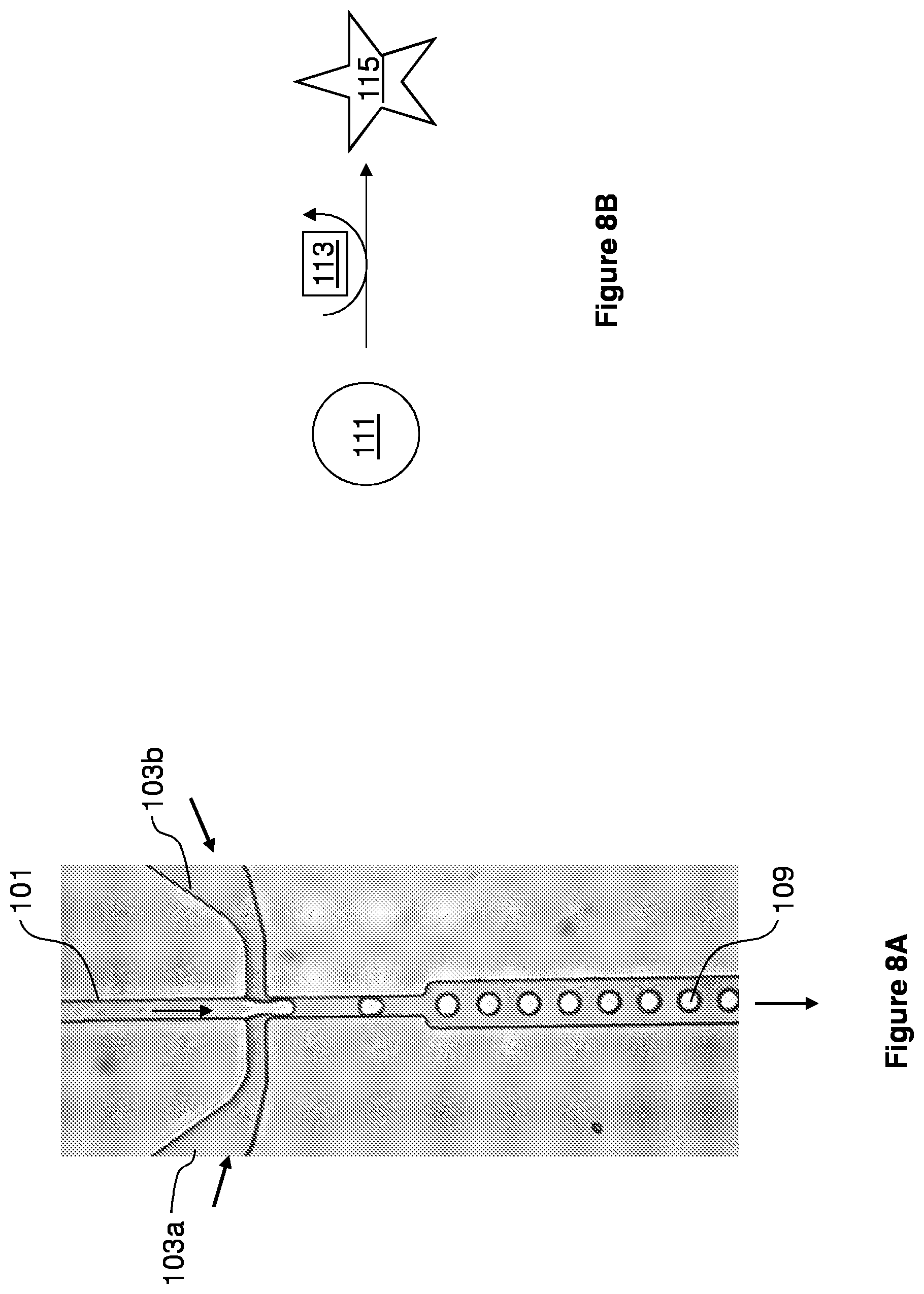
D00009
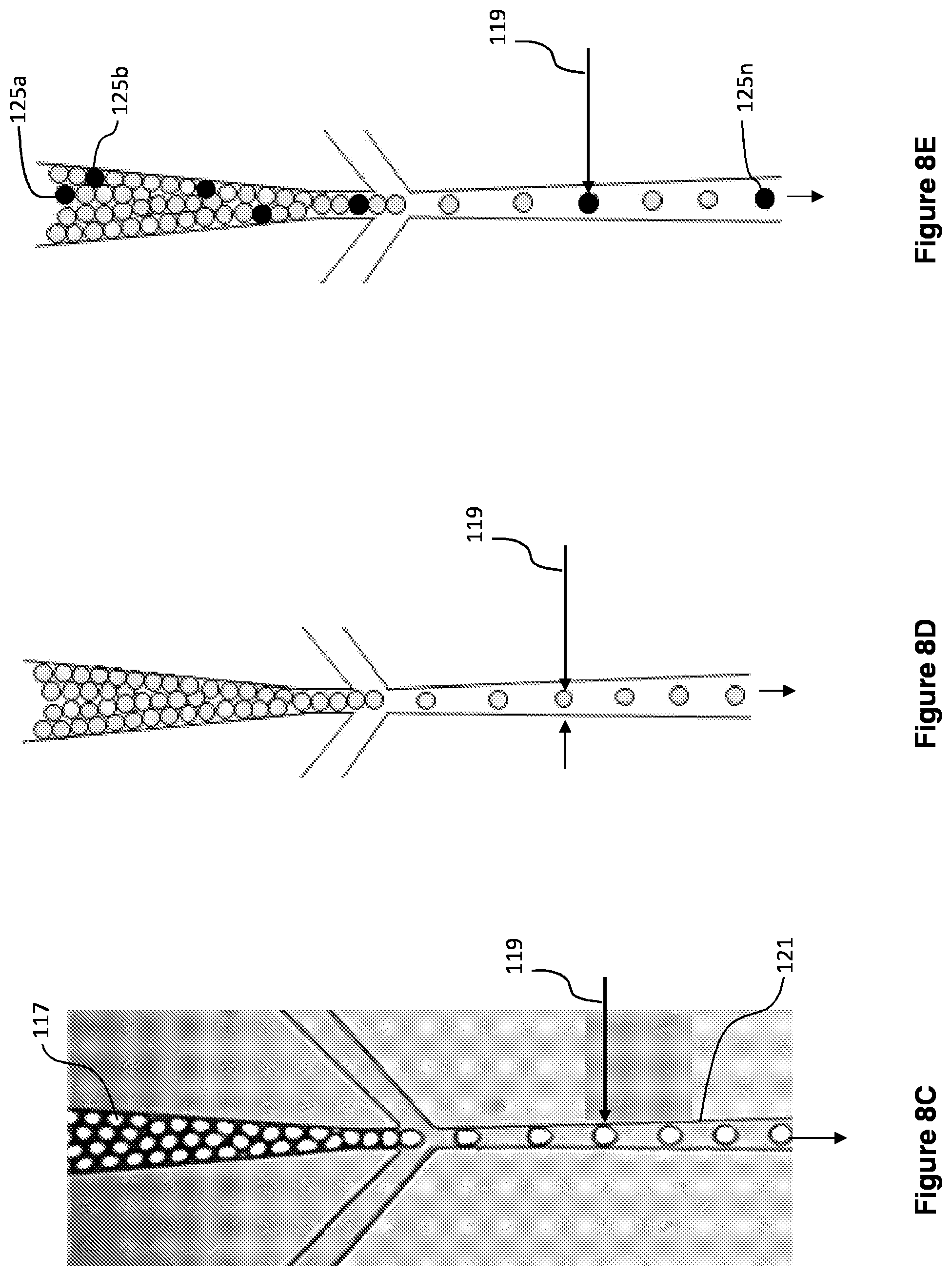
D00010
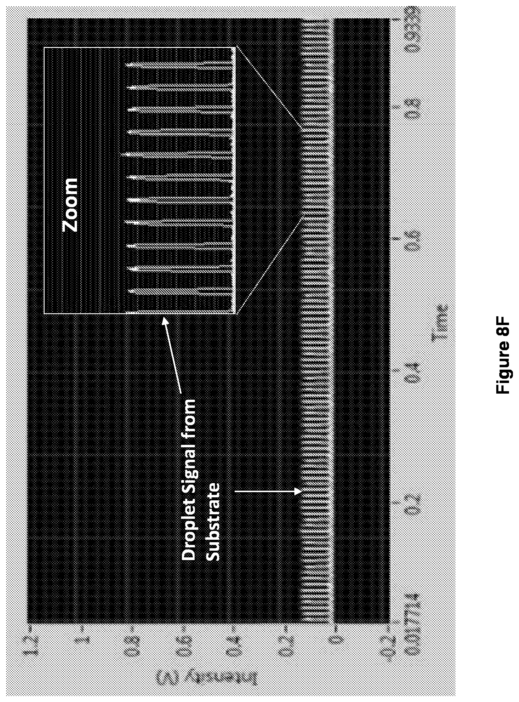
D00011

D00012
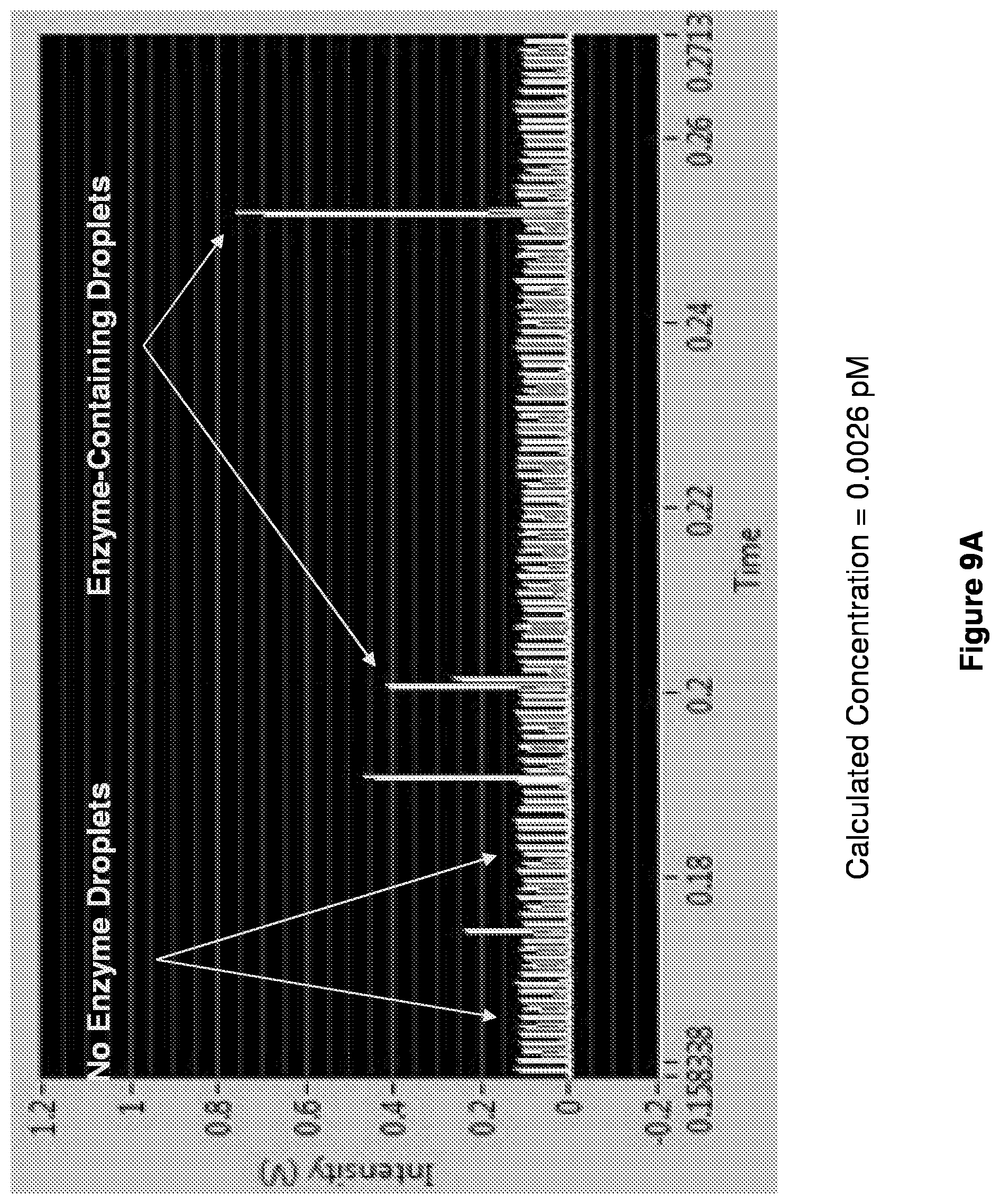
D00013

D00014

D00015
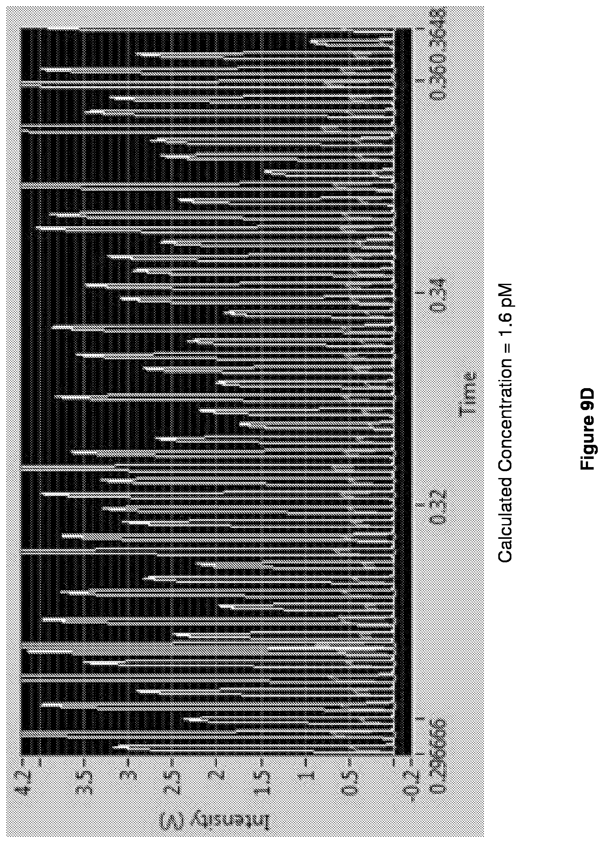
D00016

D00017
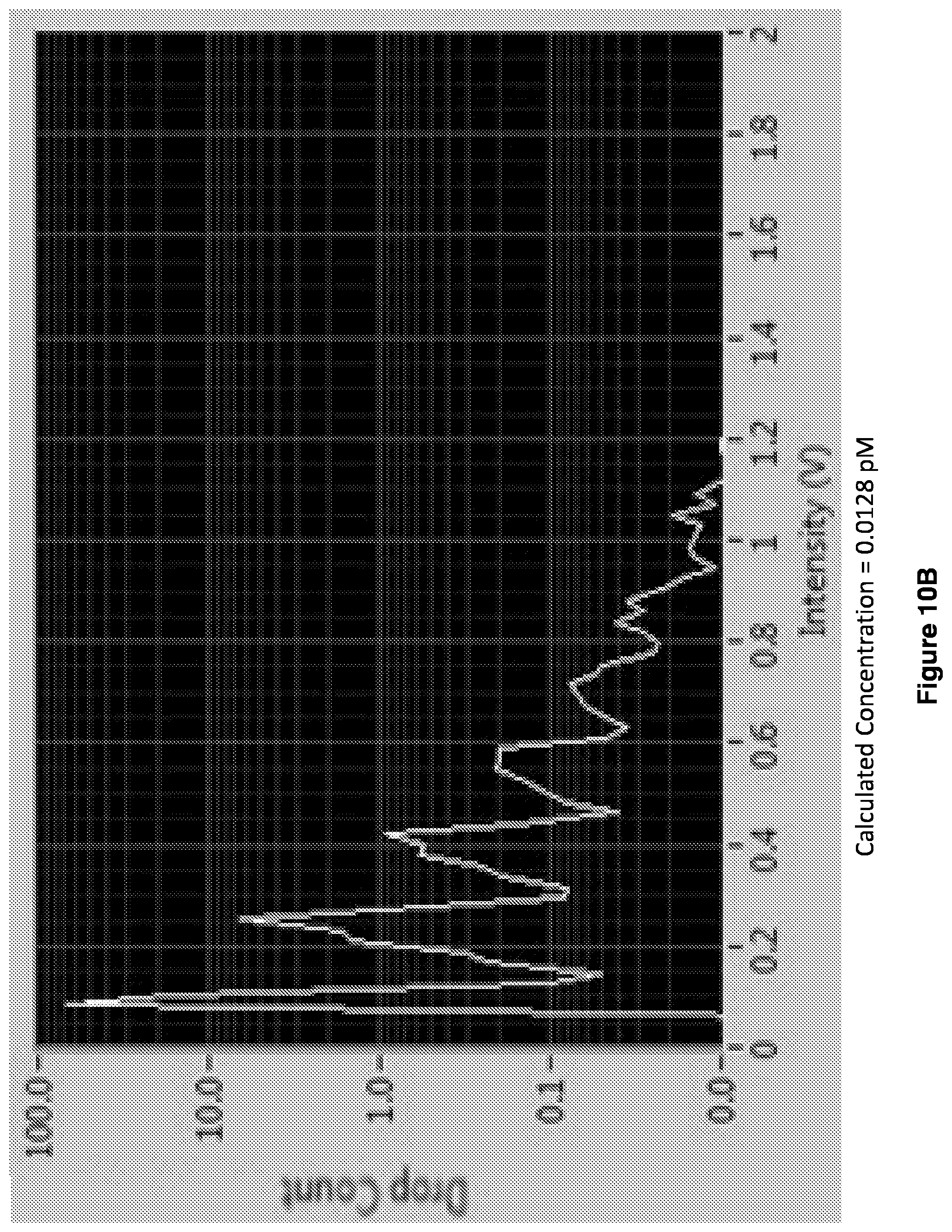
D00018
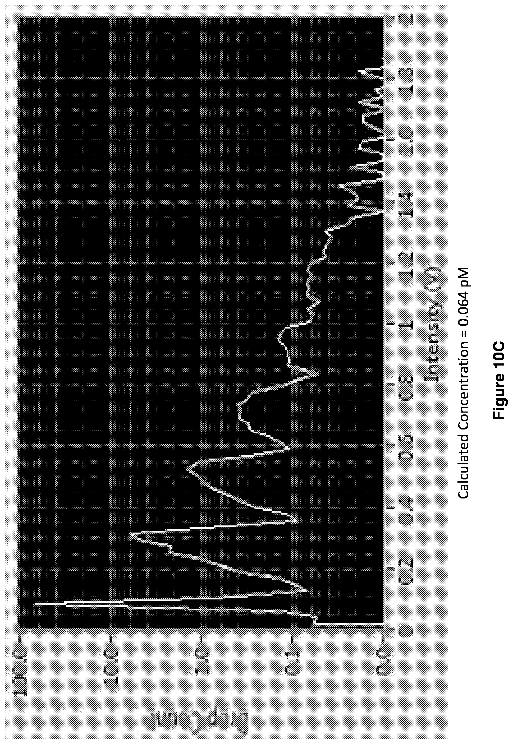
D00019
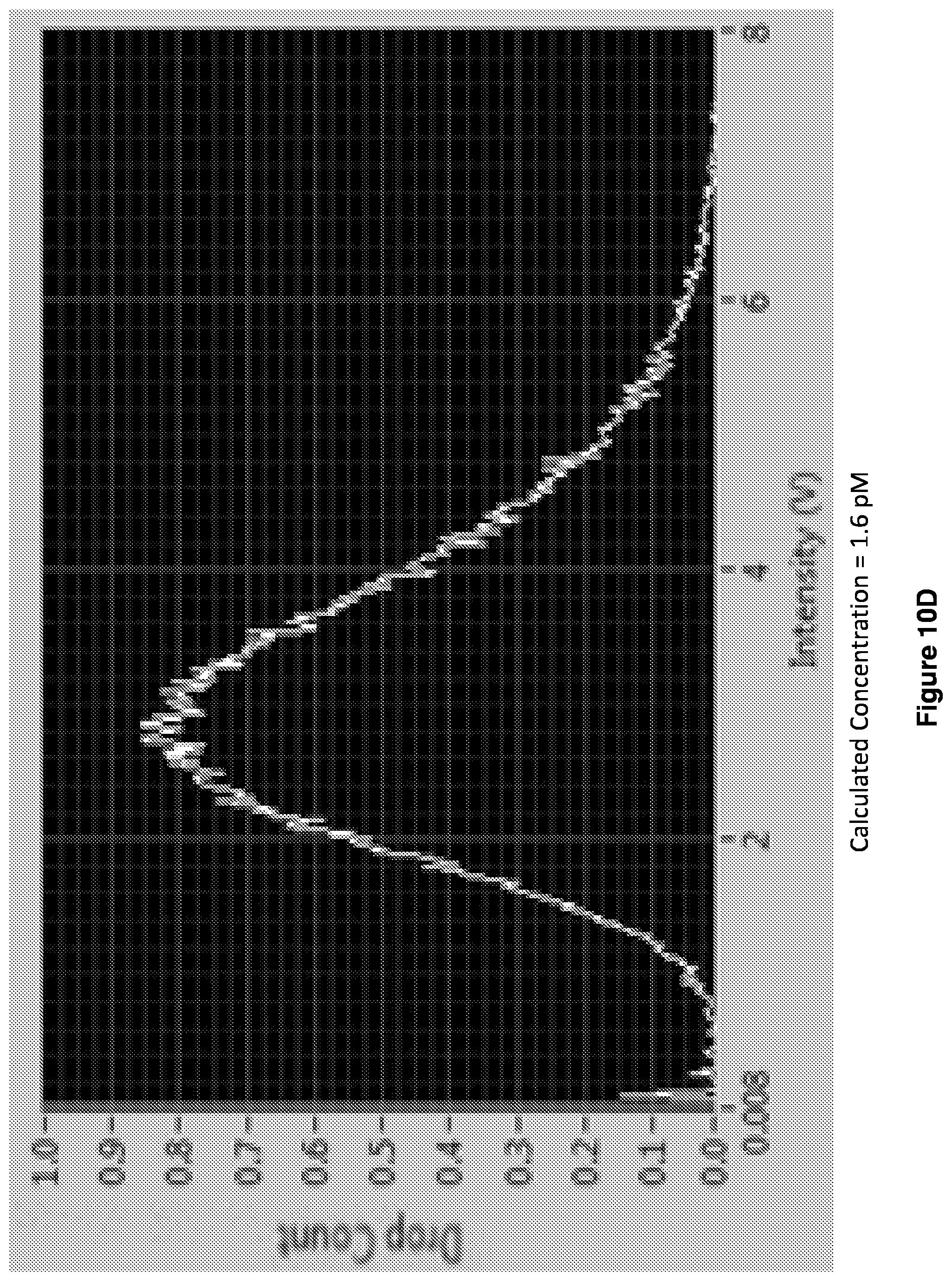
D00020

D00021

D00022

D00023
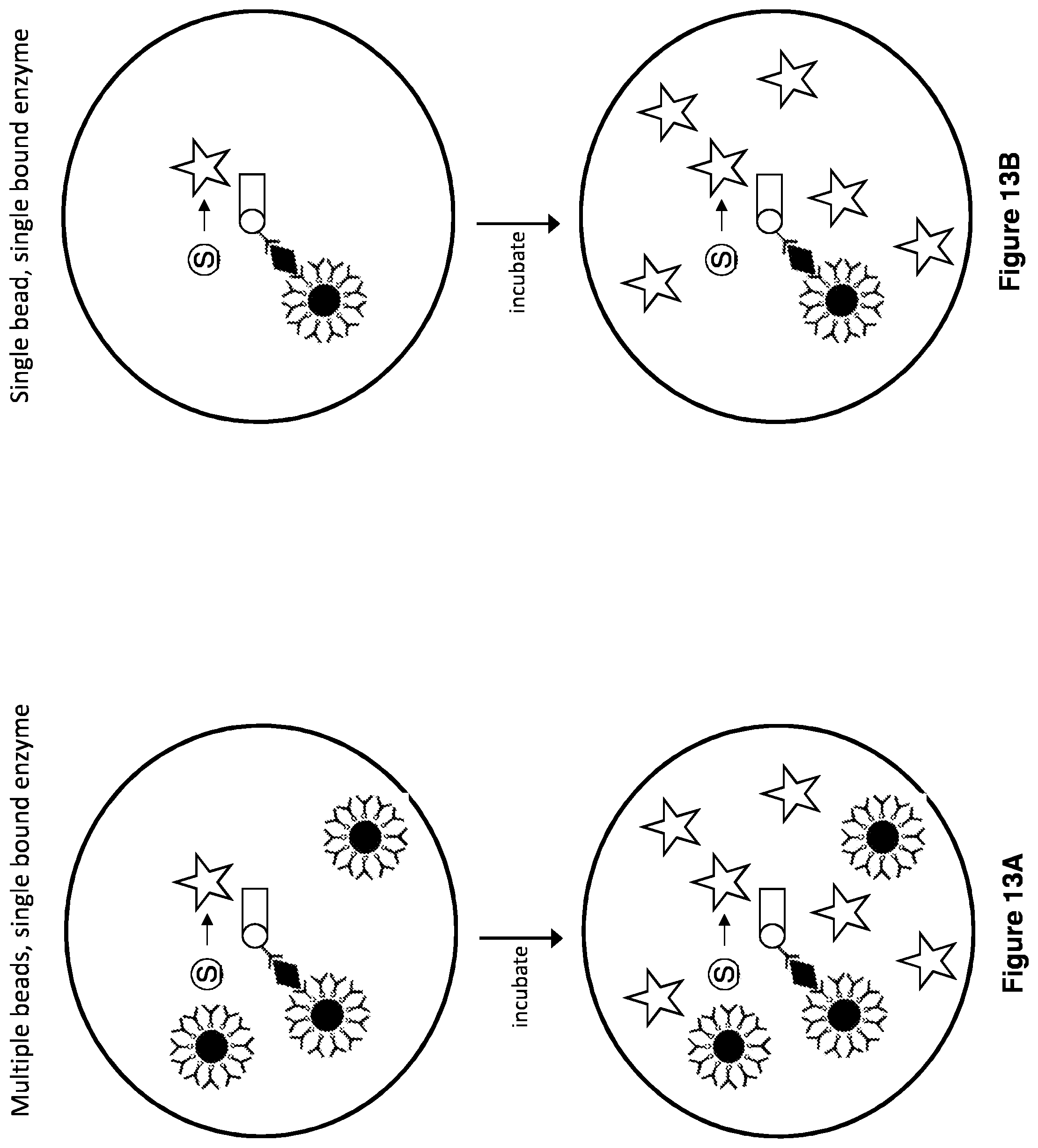
D00024

D00025
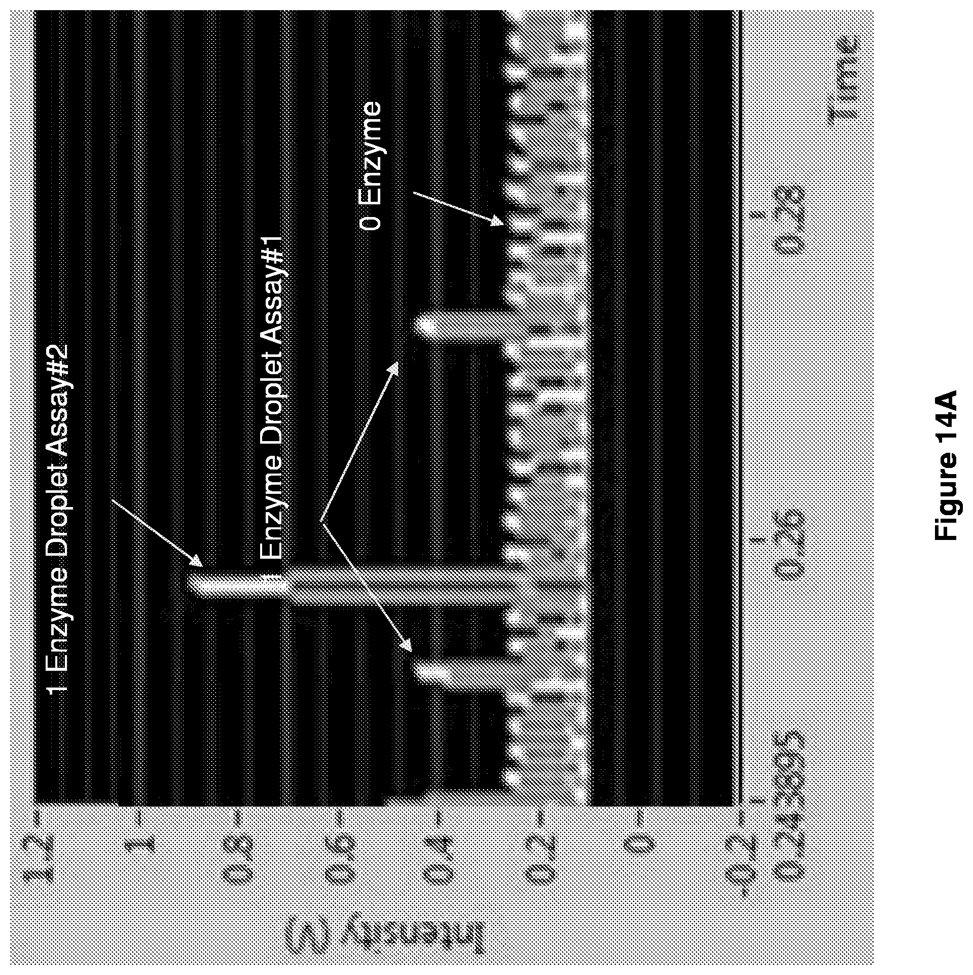
D00026
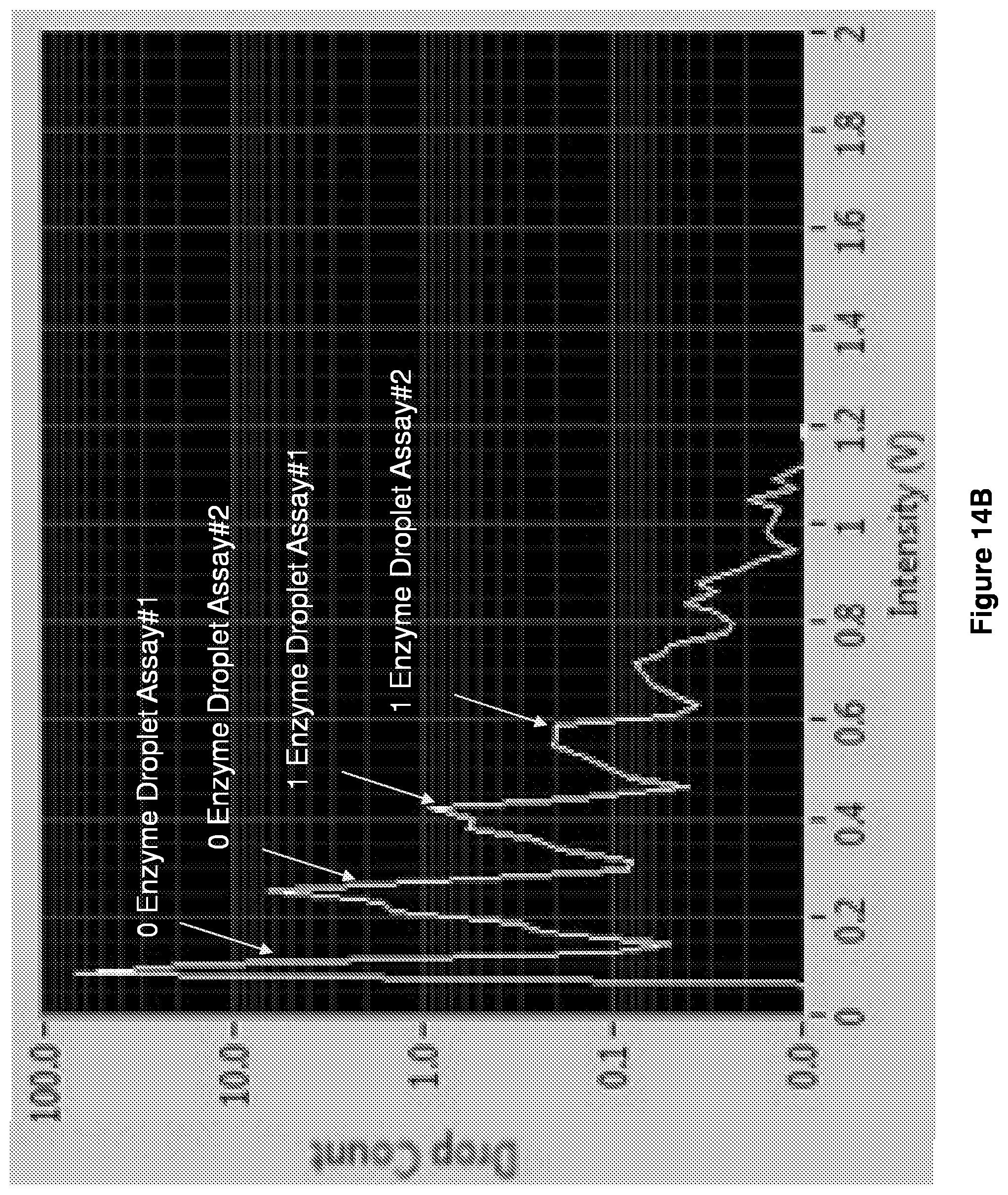
D00027

D00028

D00029

D00030
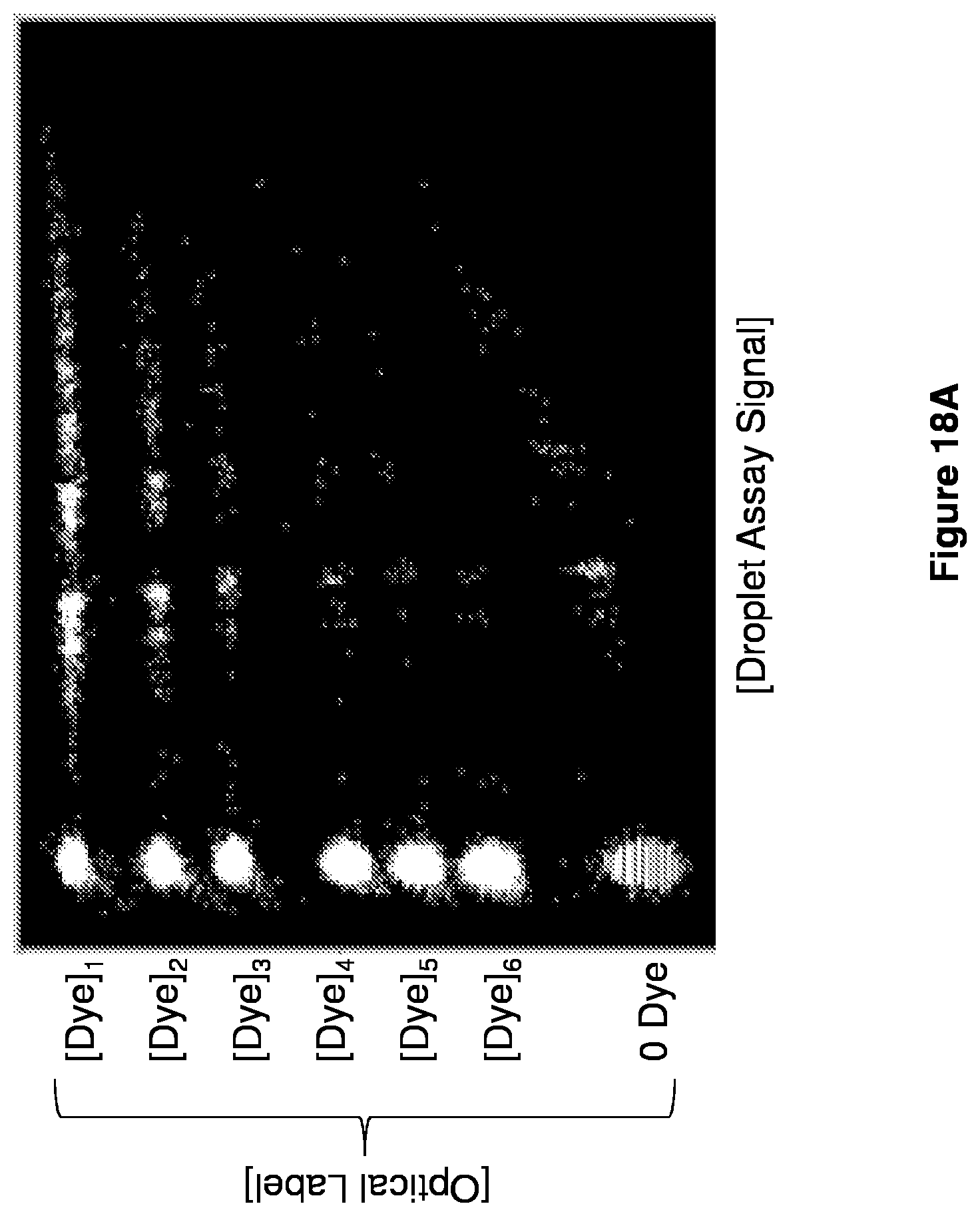
D00031

D00032
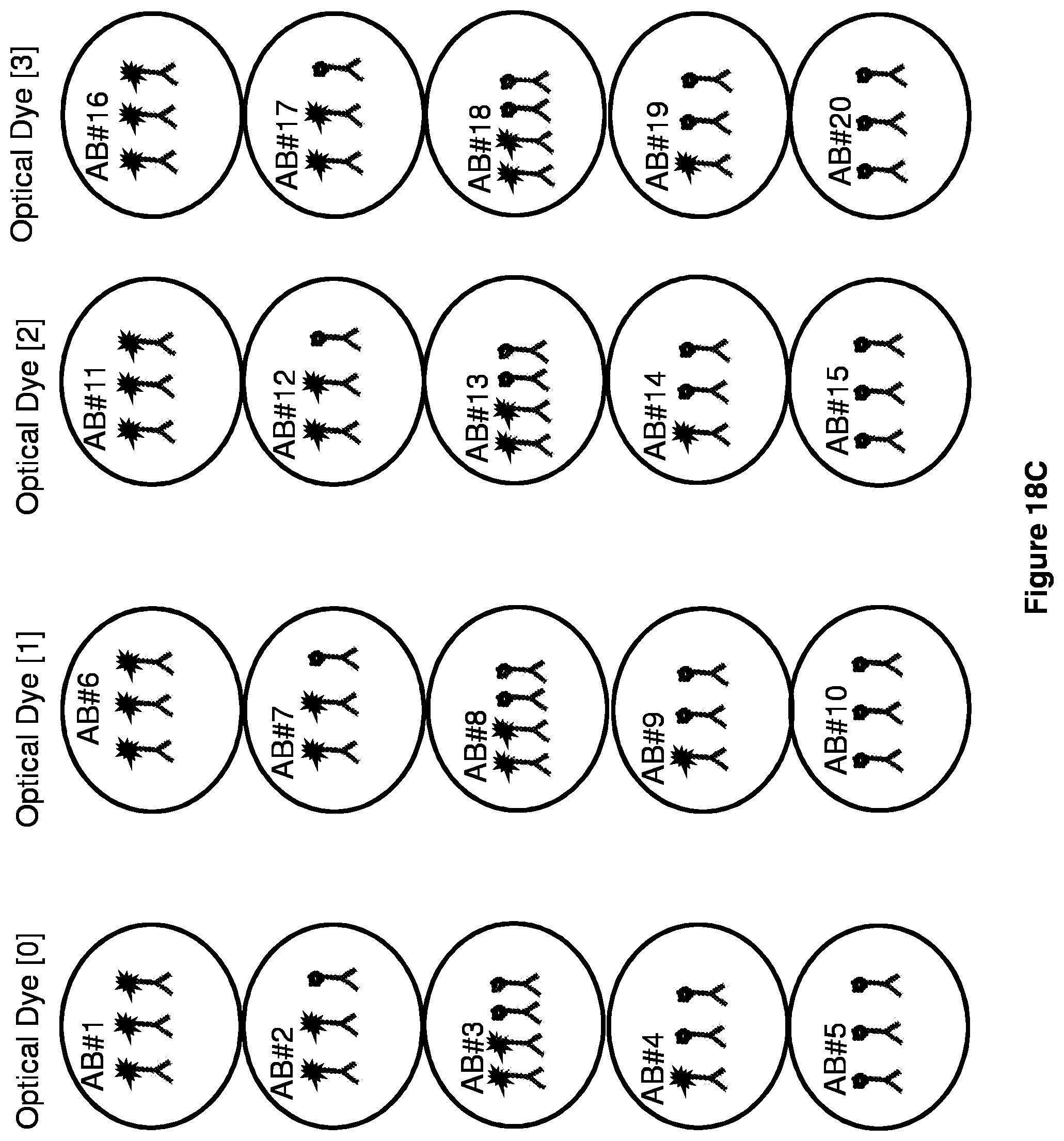
D00033

D00034

D00035

D00036

D00037

D00038
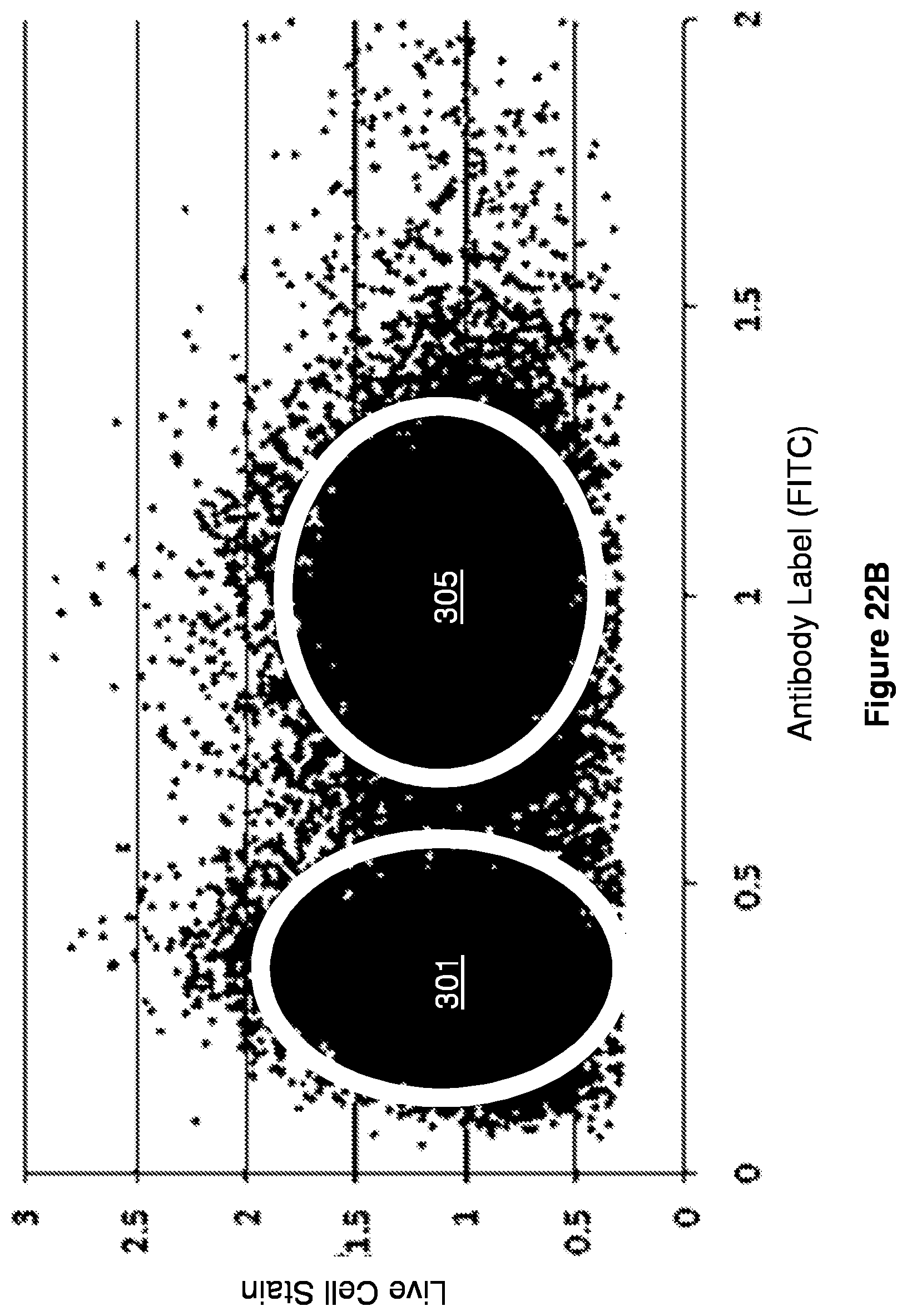
D00039

D00040

D00041

D00042

D00043
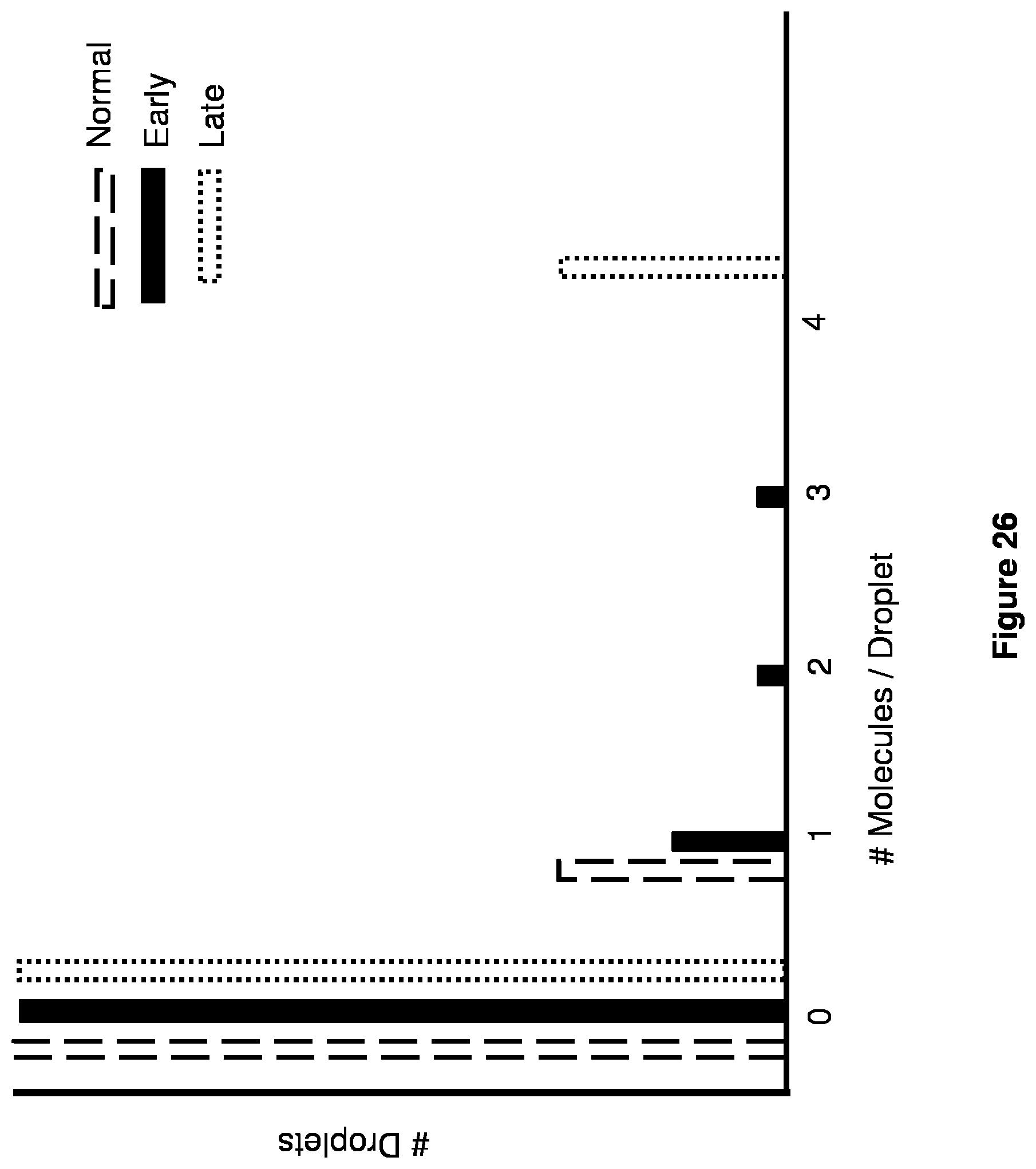


XML
uspto.report is an independent third-party trademark research tool that is not affiliated, endorsed, or sponsored by the United States Patent and Trademark Office (USPTO) or any other governmental organization. The information provided by uspto.report is based on publicly available data at the time of writing and is intended for informational purposes only.
While we strive to provide accurate and up-to-date information, we do not guarantee the accuracy, completeness, reliability, or suitability of the information displayed on this site. The use of this site is at your own risk. Any reliance you place on such information is therefore strictly at your own risk.
All official trademark data, including owner information, should be verified by visiting the official USPTO website at www.uspto.gov. This site is not intended to replace professional legal advice and should not be used as a substitute for consulting with a legal professional who is knowledgeable about trademark law.