Wine Cooler Capable Of Reducing Power Consumption
Wu; Weiwen ; et al.
U.S. patent application number 16/245662 was filed with the patent office on 2020-07-16 for wine cooler capable of reducing power consumption. This patent application is currently assigned to Zhongshan Candor Electric Appliances Co., Ltd.. The applicant listed for this patent is Zhongshan Candor Electric Appliances Co., Ltd.. Invention is credited to Xiong Li, Dakun Wu, Weiwen Wu.
| Application Number | 20200224965 16/245662 |
| Document ID | / |
| Family ID | 71517428 |
| Filed Date | 2020-07-16 |


| United States Patent Application | 20200224965 |
| Kind Code | A1 |
| Wu; Weiwen ; et al. | July 16, 2020 |
WINE COOLER CAPABLE OF REDUCING POWER CONSUMPTION
Abstract
A wine cooler capable of reducing power consumption, including a cooler body, where a temperature adjustment device is disposed inside the cooler body, at least one cooler door is disposed on a front side of the cooler body, a plurality of locking components are disposed around edges of the cooler door, a heat insulating element used for preventing heat inside the cooler body from being dissipated to outside the cooler body is correspondingly disposed on an inner side and/or an outer side of each cooler door, and the cooler door is detachably fastened to the heat insulating element as a whole by using the plurality of locking components. The heat insulating element effectively isolates the heat inside the cooler body and prevents the heat inside the cooler body from being dissipated to outside of the cooler body through the cooler door.
| Inventors: | Wu; Weiwen; (Zhongshan City, CN) ; Wu; Dakun; (Zhongshan City, CN) ; Li; Xiong; (Zhongshan City, CN) | ||||||||||
| Applicant: |
|
||||||||||
|---|---|---|---|---|---|---|---|---|---|---|---|
| Assignee: | Zhongshan Candor Electric
Appliances Co., Ltd. |
||||||||||
| Family ID: | 71517428 | ||||||||||
| Appl. No.: | 16/245662 | ||||||||||
| Filed: | January 11, 2019 |
| Current U.S. Class: | 1/1 |
| Current CPC Class: | F25D 2331/803 20130101; F25D 2300/00 20130101; F25D 2201/00 20130101; F25D 31/007 20130101 |
| International Class: | F25D 31/00 20060101 F25D031/00 |
Claims
1. A wine cooler capable of reducing power consumption, comprising: a cooler body, wherein a temperature adjustment device is disposed inside the cooler body, at least one cooler door is disposed on a front side of the cooler body, a plurality of locking components are disposed around edges of the cooler door, a heat insulating element used for blocking exchange between heat inside the cooler body and heat outside the cooler body is attached to an inner side and/or an outer side of each cooler door, and the heat insulating element is detachably fastened to the cooler door as a whole by using the plurality of locking components.
2. The wine cooler capable of reducing power consumption according to claim 1, wherein the cooler door is a glass cooler door, the cooler door comprises a fixed frame of a rectangle structure and a glass panel disposed inside the fixed frame, the plurality of locking components are disposed at a periphery of the fixed frame, and peripheral edges of the heat insulating element are detachably connected to the fixed frame by using the plurality of locking components and attached to an outer side surface or an inner side surface of the glass panel.
3. The wine cooler capable of reducing power consumption according to claim 2, wherein the detachable manner includes at least one of the following: a clamping connection, an adsorption connection, a buckling connection, a plug connection, and a hinge connection.
4. The wine cooler capable of reducing power consumption according to claim 3, wherein when the heat insulating element and the cooler door are disposed on an outer side surface or an inner side surface of the cooler door in a clamped manner, at least one clamping element is disposed at each of three side edges of an outer side wall or an inner side wall of the fixed frame, the clamping element comprises a connecting end and a clamping end, the connecting end is connected to the fixed frame, the clamping end extends inwards in a centering direction of the fixed frame, and a plurality of clamping elements cooperate with each other to fasten and clamp the heat insulating element to the outer side surface or the inner side surface of the cooler door.
5. The wine cooler capable of reducing power consumption according to claim 3, wherein when the heat insulating element and the fixed frame are disposed on an outer side surface or an inner side surface of the cooler door in an adsorption manner, one or more first adsorption elements are disposed at each of peripheral edges of an outer side wall or an inner side wall of the fixed frame, at least one second adsorption element is disposed at each of peripheral edges of a side surface of the heat insulating element, the second adsorption element and the first adsorption element are disposed correspondingly, and each second adsorption element and one first adsorption element attract each other to make the heat insulating element adsorbed to the outer side surface or the inner side surface of the cooler door.
6. The wine cooler capable of reducing power consumption according to claim 5, wherein the first adsorption element and the second adsorption element are magnets; or the first adsorption element is a magnet and the second adsorption element is an iron block; or the first adsorption element is an iron block and the second adsorption element is a magnet.
7. The wine cooler capable of reducing power consumption according to claim 3, wherein when the heat insulating element and the cooler door are disposed on an outer side surface or an inner side surface of the cooler door in a buckled manner, at least one fixing element is disposed at each of peripheral edges of an outer side wall or an inner side wall of the fixed frame, each fixing element has a hollow structure and a fixing hole is disposed in a side wall of the fixing element, chucking elements whose quantity is the same as that of fixing elements are respectively disposed at positions, corresponding to the fixing elements, on a side surface of the heat insulating element, an elastic clamping part is disposed at a position, corresponding to the fixing hole, on an outer side wall of the chucking element; and when the heat insulating element is connected to the cooler door, the chucking element is inserted into the fixing element, and the clamping part is clamped in the fixing hole to fasten the heat insulating element to the outer side surface or the inner side surface of the cooler door.
8. The wine cooler capable of reducing power consumption according to claim 2, wherein an area of the heat insulating element is matched with an area of the glass panel.
9. The wine cooler capable of reducing power consumption according to claim 3, wherein an area of the heat insulating element is matched with an area of the glass panel.
10. The wine cooler capable of reducing power consumption according to claim 4, wherein an area of the heat insulating element is matched with an area of the glass panel.
11. The wine cooler capable of reducing power consumption according to claim 5, wherein an area of the heat insulating element is matched with an area of the glass panel.
12. The wine cooler capable of reducing power consumption according to claim 6, wherein an area of the heat insulating element is matched with an area of the glass panel.
13. The wine cooler capable of reducing power consumption according to claim 7, wherein an area of the heat insulating element is matched with an area of the glass panel.
Description
TECHNICAL FIELD
[0001] The present invention generally relates to the field of wine cooler technologies, and in particular, to a wine cooler capable of reducing power consumption.
BACKGROUND
[0002] A wine cooler, as electrical equipment commonly used in homes, can be used for decoration in addition to wine storage. In addition, to ensure the storage quality of a wine cooler, a temperature adjustment device is usually disposed inside an existing wine cooler. The temperature adjustment device can adjust temperature of air inside the wine cooler, to ensure that wine placed inside the wine cooler is in a suitable environment. However, an existing cooler door is generally made of a glass material, and due to relatively poor air-tightness of the cooler door made of a glass material, heat inside the wine cooler is easily dissipated from the cooler door to outside the cooler body. As a result, the temperature adjustment device is always in a high-intensity running state, leading to high power consumption of the wine cooler and a waste of a large amount of electric energy.
SUMMARY
(1) Objective of the Present Invention
[0003] To overcome the foregoing advantage, the objective of the present invention is to provide a wine cooler capable of reducing power consumption, to resolve a problem that high power consumption of a wine cooler is caused because heat inside the existing wine cooler is easily dissipated.
(2) Technical Solution
[0004] To achieve the above objective, the present invention provides the following technical solution:
[0005] A wine cooler capable of reducing power consumption, including:
[0006] a cooler body, where a temperature adjustment device is disposed inside the cooler body, at least one cooler door is disposed on a front side of the cooler body, a plurality of locking components are disposed around edges of the cooler door, a heat insulating element used for blocking exchange between heat inside the cooler body and heat outside the cooler body is attached to an inner side and/or an outer side of each cooler door, and the heat insulating element is detachably fastened to the cooler door as a whole by using the plurality of locking components.
[0007] Further, the cooler door is a glass cooler door, the cooler door includes a fixed frame of a rectangle structure and a glass panel disposed inside the fixed frame, the plurality of locking components are disposed at a periphery of the fixed frame, and peripheral edges of the heat insulating element are detachably connected to the fixed frame by using the plurality of locking components and attached to an outer side surface or an inner side surface of the glass panel.
[0008] Further, the detachable manner is clamping connection, adsorption connection, buckling connection, plug connection, or hinge connection.
[0009] Further, when the heat insulating element and the cooler door are disposed on an outer side surface or an inner side surface of the cooler door in a clamped manner, at least one clamping element is disposed at each of three side edges of an outer side wall or an inner side wall of the fixed frame, the clamping element includes a connecting end and a clamping end, the connecting end is connected to the fixed frame, the clamping end extends inwards in a centering direction of the fixed frame, and a plurality of clamping elements cooperate with each other to fasten and clamp the heat insulating element to the outer side surface or the inner side surface of the cooler door.
[0010] Further, when the heat insulating element and the fixed frame are disposed on an outer side surface or an inner side surface of the cooler door in an adsorption manner, one or more first adsorption elements are disposed at each of peripheral edges of an outer side wall or an inner side wall of the fixed frame, at least one second adsorption element is disposed at each of peripheral edges of a side surface of the heat insulating element, the second adsorption element and the first adsorption element are disposed correspondingly, and each second adsorption element and one first adsorption element attract each other to make the heat insulating element adsorbed to the outer side surface or the inner side surface of the cooler door.
[0011] Further, the first adsorption element and the second adsorption element are magnets; or the first adsorption element is a magnet and the second adsorption element is an iron block; or the first adsorption element is an iron block and the second adsorption element is a magnet.
[0012] Further, when the heat insulating element and the cooler door are disposed on an outer side surface or an inner side surface of the cooler door in a buckled manner, at least one fixing element is disposed at each of peripheral edges of an outer side wall or an inner side wall of the fixed frame, each fixing element has a hollow structure and a fixing hole is disposed in a side wall of the fixing element, chucking elements whose quantity is the same as that of fixing elements are respectively disposed at positions, corresponding to the fixing elements, on a side surface of the heat insulating element, an elastic clamping part is disposed at a position, corresponding to the fixing hole, on an outer side wall of the chucking element; and when the heat insulating element is connected to the cooler door, the chucking element is inserted into the fixing element, and the clamping part is clamped in the fixing hole to fasten the heat insulating element to the outer side surface or the inner side surface of the cooler door.
[0013] Further, an area of the heat insulating element is matched with an area of the glass panel.
(3) Beneficial Effects
[0014] Based on the foregoing technical solution, the beneficial effects of the present invention are as follows:
[0015] 1. A heat insulating element is disposed on a cooler door of a wine cooler with a heat insulating function, and can effectively isolate heat inside the wine cooler, and prevent the heat inside the cooler body from being dissipated to outside the cooler body, so as to prevent a temperature adjustment device inside the cooler body from being in a running state for a long time, and greatly reduce power consumption of the wine cooler.
[0016] 2. The heat insulating element is fastened to the cooler door in a manner of clamping connection, adsorption connection, buckling connection, plug connection, hinge connection, or another detachable connection, and when there is a need to view wine inside the wine cooler, the heat insulating element can be removed from the cooler door, and then the heat insulating element is fastened to the cooler door after viewing is ended, thereby expanding an application range of the wine cooler.
BRIEF DESCRIPTION OF THE DRAWINGS
[0017] The present invention is described with reference to the accompanying drawings. In the drawings, like reference numbers indicate identical or functionally similar elements. Additionally, the left-most digit(s) of a reference number identifies the drawing in which the reference number first appears.
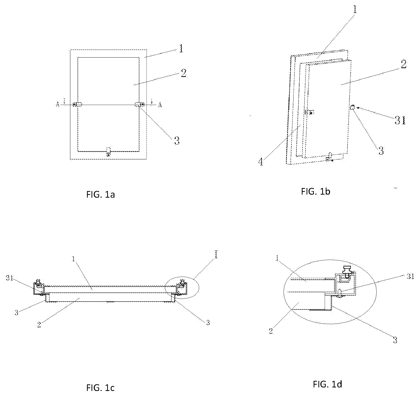
[0018] FIG. 1a is a schematic structural diagram of a first embodiment of an exemplary wine cooler capable of reducing power consumption according to the present invention;
[0019] FIG. 1b is a schematic decomposition diagram of a first embodiment of an exemplary wine cooler capable of reducing power consumption, according to some implementations of the present invention;
[0020] FIG. 1c is a cross-section diagram in an A-A direction in FIG. 1a;
[0021] FIG. 1d is a cross-section diagram in a direction of an I part in FIG. 1c;
[0022] FIG. 2a is a schematic structural diagram of a second embodiment of an exemplary wine cooler capable of reducing power consumption, according to some implementations of the present invention;
[0023] FIG. 2b is a schematic decomposition diagram of a second embodiment of an exemplary wine cooler capable of reducing power consumption, according to some implementations of the present invention;
[0024] FIG. 2c is a cross-section diagram in an A-A direction in FIG. 2a;
[0025] FIG. 2d is a cross-section diagram in a direction of an II part in FIG. 2c;
[0026] FIG. 3a is a schematic structural diagram of a third embodiment of an exemplary wine cooler capable of reducing power consumption, according to some implementations of the present invention;
[0027] FIG. 3b is a schematic decomposition diagram of a third embodiment of an exemplary wine cooler capable of reducing power consumption, according to some implementations of the present invention;
[0028] FIG. 3c is a cross-section diagram in an A-A direction in FIG. 3a;
[0029] FIG. 3d is a cross-section diagram in a direction of an III part in FIG. 3c;
[0030] FIG. 4a is a schematic structural diagram of a fourth embodiment of an exemplary wine cooler capable of reducing power consumption, according to some implementations of the present invention;
[0031] FIG. 4b is a schematic decomposition diagram of a fourth embodiment of an exemplary wine cooler capable of reducing power consumption, according to some implementations of the present invention;
[0032] FIG. 4c is a cross-section diagram in an A-A direction in FIG. 4a;
[0033] FIG. 4d is a cross-section diagram in a direction of an IV part in FIG. 4c;
[0034] FIG. 5a is a schematic structural diagram of a fifth embodiment of an exemplary wine cooler capable of reducing power consumption, according to some implementations of the present invention;
[0035] FIG. 5b is a schematic decomposition diagram of a fifth embodiment of an exemplary wine cooler capable of reducing power consumption, according to some implementations of the present invention;
[0036] FIG. 5c is a cross-section diagram in an A-A direction in FIG. 5a;
[0037] FIG. 5d is a cross-section diagram in a direction of a V part in FIG. 5c;
[0038] FIG. 6a is a schematic structural diagram of a sixth embodiment of an exemplary wine cooler capable of reducing power consumption, according to some implementations of the present invention;
[0039] FIG. 6b is a schematic decomposition diagram of a sixth embodiment of an exemplary wine cooler capable of reducing power consumption, according to some implementations of the present invention;
[0040] FIG. 6c is a cross-section diagram in an A-A direction in FIG. 5a; and
[0041] FIG. 6d is a cross-section diagram in a direction of an IV part in FIG. 5c.
REFERENCE SIGNS
[0042] 1: Fixed frame; 2: heat insulating element; 3: clamping element; 31: screw; 4: glass panel; 5: first adsorption element; 6: second adsorption element; 7: fixing element; 8: chucking element.
DETAILED DESCRIPTION
[0043] To make the objective, technical solution, and advantages of the present invention clearer, the following further describes the present invention in details with reference to specific implementations and the accompanying drawings. It should be understood that the description is only exemplary and is not intended to limit the scope of the present invention. In addition, in the following description, the description of a well-known structure and technology is omitted to avoid unnecessary confusion of concepts in the present invention.
[0044] Referring to FIG. 1a to FIG. 6d, a wine cooler capable of reducing power consumption provided in the present invention includes: a cooler body, where a temperature adjustment device is disposed inside the cooler body, at least one cooler door is disposed on a front side of the cooler body, a plurality of locking components are disposed around edges of the cooler door, a heat insulating element 2 used for blocking exchange between heat inside the cooler body and heat outside the cooler body is correspondingly disposed on an inner side and/or an outer side of each cooler door, and the cooler door is detachably fastened to the heat insulating element 2 as a whole by using the plurality of locking components. It should be noted that the heat insulating element 2 may be disposed on an outer side surface and an inner side surface of the cooler door or may be disposed on both a front side and a rear side of the cooler door, and the heat insulating element 2 disposed on any side surface of the cooler body can effectively isolate the heat inside the cooler body, and prevent the heat inside the cooler body from being dissipated to outside the cooler body. A position at which the heat insulating element 2 is disposed is not limited in this implementation. To ensure air-tightness inside the wine cooler, preferably, an area of the heat insulating element 2 is matched with an area of a glass panel of the cooler door.
[0045] The cooler door in the present invention is a glass cooler door, and the cooler door includes a fixed frame 1 of a rectangle structure and the glass panel 4 clamped inside the fixed frame 1, and peripheral edges of the heat insulating element 2 are detachably connected to the fixed frame 1 and cover a front surface or a back surface of the glass panel 4.
[0046] The heat insulating element 2 may be made of a plurality of types of heat insulating materials, for example, the heat insulating element 2 may be made of a foam material or heat insulation cotton. By installing the heat insulating element 2, the heat inside the cooler body can be effectively prevented from being dissipated to outside the cooler body, and when temperature inside the cooler body reaches appropriate predetermined temperature, the temperature adjustment device disposed inside the cooler body can temporarily stop running or reduce the operating intensity, so as to greatly reduce a power loss of the wine cooler, to achieve effects of energy saving and emission reduction.
[0047] To make the wine cooler also have a viewing value, the heat insulating element 2 is detachably connected to the cooler door, and the detachable connection between the cooler door and the heat insulating element 2 may be clamping connection, adsorption connection, buckling connection, plug connection, hinge connection, or another detachable connection. During viewing of the wine cooler, the heat insulating element 2 is removed from the cooler door, and the heat insulating element 2 is fastened to the cooler door after viewing is ended, to isolate the heat inside the cooler body.
[0048] Referring to FIG. 1a to FIG. 1d, in a first implementation manner, the heat insulating element 2 is connected to the cooler door in a clamped manner; one end of a clamping element 3 is a connecting end and another end thereof is a clamping end; when the heat insulating element 2 is disposed on an outer side surface of the cooler door, one clamping element 3 is disposed at each of edges of a left side, a right side, and a bottom side of an outer side wall of the fixed frame 1. Specifically, the clamping element 3 has a "zigzag" structure; the connecting end of the clamping element 3 is connected to the fixed frame 1 by using a screw 31, the clamping elements 3 on the left side and the right side of the fixed frame 1 are transversely disposed, the clamping element 3 on the bottom side of the fixed frame 1 is vertically disposed, and accommodated space for fastening the heat insulating element 2 is formed between the plurality of clamping elements 3 and the cooler door. When the heat insulating element 2 is fastened to the cooler door, the clamping elements 3 on the left side and the right side press tightly a left side and a right side of the heat insulating element 2, the clamping element 3 on the bottom side presses tightly and bears the heat insulating element 2, to fasten the heat insulating element 2 to the outer side surface of the cooler door.
[0049] Referring to FIG. 2a to FIG. 2d, in a second implementation manner, the heat insulating element 2 is disposed on an inner side surface of the cooler door. Because a structure and a connection manner used when the heat insulating element 2 is disposed on the inner side surface of the cooler door is roughly the same as that used when the heat insulating element 2 is disposed on the outer side surface of the cooler door, a manner in which the heat insulating element 2 is disposed on the inner side surface of the cooler door is not described herein in details.
[0050] Referring to FIG. 3a to FIG. 3d and FIG. 4a to FIG. 4d, in a third and fourth implementation manners, the heat insulating element 2 is disposed on an outer side surface or an inner side surface of the cooler door in an adsorption manner.
[0051] When the heat insulating element 2 is disposed on the outer side surface or the inner side surface of the cooler door, one or more first adsorption elements 5 are disposed at each of peripheral edges of an outer side wall or an inner side wall of the fixed frame 1, one or more second adsorption elements 6 are disposed at each of peripheral edges of a side surface of the heat insulating element 2, the second adsorption element 6 and the first adsorption element 5 are disposed correspondingly, and each second adsorption element 6 and one first adsorption element 5 attract each other to make the heat insulating element 2 adsorbed to the outer side surface or the inner side surface of the cooler door. Optionally, the first adsorption element and the second adsorption element 6 may be two magnets that attract each other; or the first adsorption element 5 is a magnet and the second adsorption element 6 is an iron block; or the first adsorption element 5 is an iron block and the second adsorption element 6 is a magnet. During fastening the heat insulating element 2 to the cooler door, the heat insulating element 2 may be fastened to the cooler door only through adsorption between the first adsorption element and the second adsorption element 6.
[0052] Referring to FIG. 5a to FIG. 5d and FIG. 6a to FIG. 6d, in a fifth and sixth implementation manners, the heat insulating element 2 is connected to the cooler door in a buckled manner, when the heat insulating element 2 is disposed on an outer side surface or an inner side surface of the cooler door, at least one fixing element 7 is disposed at each of peripheral edges of an outer side wall or an inner side wall of the fixed frame 1, each fixing element 7 has a hollow structure and a fixing hole is disposed in a side wall of the fixing element 7, at least one chucking element 8 inserted into the fixing element 7 is disposed at each of peripheral edges of a side surface of the heat insulating element 2, a structure of the chucking element 8 is matched with that of the fixing element 7, an elastic clamping part of a triangular structure is disposed at a position, corresponding to the fixing hole, on an outer side wall of the chucking element 8; and when the heat insulating element 2 is connected to the cooler door, the chucking element 8 is inserted into the fixing element 7, and the clamping part is clamped in the fixing hole to fasten the heat insulating element 2 to the outer side surface or the inner side surface of the cooler door.
[0053] Technical effects of the present invention are described below by using a specific example:
TABLE-US-00001 TABLE 1 Whether a heat insulating element Unit Power Group is disposed? Specification time consumption Control group The heat insulating 20 L 24 h 0.900 kwh element is not disposed. Test group The heat insulating 20 L 24 h 0.598 kwh element is disposed.
[0054] It can be seen from Table 1 that the power consumption of the wine cooler is greatly reduced after the installation of the heat insulating element 2. The power consumption of the wine cooler in which the heat insulating element 2 is disposed (test group) in one day is 33% lower than that of the wine cooler in which the heat insulating element 2 is not disposed (control group). The wine cooler has an obvious energy saving effect and satisfies a requirement of green environmental protection. In the present invention, it can be learned from a large amount of analysis and test experimental data that, when a capacity of the wine cooler is larger, the energy saving effect of the wine cooler is more obvious.
[0055] It should be noted that, the foregoing listed detachable connection manners and the constituent materials of the heat insulating element 2 are merely examples. In the present invention, the heat insulating element 2 may be fastened to the cooler door in a plurality of detachable connection manners, and the heat insulating element 2 may alternatively made of different heat insulating materials. The detachable connection manner of the heat insulating element 2 and the heat insulating material of the heat insulating element 2 are not limited in the present invention.
[0056] In some implementations, the current subject matter relates to a wine cooler capable of reducing power consumption, including a cooler body, where a temperature adjustment device is disposed inside the cooler body, at least one cooler door is disposed on a front side of the cooler body, a plurality of locking components are disposed around edges of the cooler door, a heat insulating element used for preventing heat inside the cooler body from being dissipated to outside the cooler body is correspondingly disposed on an inner side and/or an outer side of each cooler door, and the cooler door is detachably fastened to the heat insulating element as a whole by using the plurality of locking components. The heat insulating element, detachably disposed on the cooler door, can effectively isolate the heat inside the cooler body from heat outside the cooler body, and prevent the heat inside the cooler body from being dissipated to outside the cooler body through the cooler door, so as to avoid a loss of a large amount of electric energy caused because the temperature adjustment device inside the cooler body is in a running state for a long time. The heat insulating element is detachably fastened to the cooler door, and a user can remove the heat insulating element from the wine cooler at any time when viewing wine in the wine cooler, thereby improving practicality of the wine cooler.
[0057] It should be understood that the foregoing specific implementations in the present invention are merely used as examples for illustration or explanation of the principle of the present invention, and do not constitute a limitation on the present invention. Therefore, any modification, equivalent replacement, or improvement made without departing from the spirit and the scope of the present invention should fall within the protection scope of the present invention. In addition, the appended claims in the present invention are intended to cover all changes and modification examples falling within the scope and boundary of the appended claims or an equivalent form of the scope and boundary.
[0058] In the descriptions above and in the claims, phrases such as "at least one of" or "one or more of" may occur followed by a conjunctive list of elements or features. The term "and/or" may also occur in a list of two or more elements or features. Unless otherwise implicitly or explicitly contradicted by the context in which it is used, such a phrase is intended to mean any of the listed elements or features individually or any of the recited elements or features in combination with any of the other recited elements or features. For example, the phrases "at least one of A and B;" "one or more of A and B;" and "A and/or B" are each intended to mean "A alone, B alone, or A and B together." A similar interpretation is also intended for lists including three or more items. For example, the phrases "at least one of A, B, and C;" "one or more of A, B, and C;" and "A, B, and/or C" are each intended to mean "A alone, B alone, C alone, A and B together, A and C together, B and C together, or A and B and C together." In addition, use of the term "based on," above and in the claims is intended to mean, "based at least in part on," such that an unrecited feature or element is also permissible.
[0059] Example embodiments of the methods and components of the present invention have been described herein. As noted elsewhere, these example embodiments have been described for illustrative purposes only, and are not limiting. Other embodiments are possible and are covered by the invention. Such embodiments will be apparent to persons skilled in the relevant art(s) based on the teachings contained herein. Thus, the breadth and scope of the present invention should not be limited by any of the above-described exemplary embodiments, but should be defined only in accordance with the following claims and their equivalents.
[0060] The subject matter described herein can be embodied in systems, apparatus, methods, and/or articles depending on the desired configuration. The implementations set forth in the foregoing description do not represent all implementations consistent with the subject matter described herein. Instead, they are merely some examples consistent with aspects related to the described subject matter. Although a few implementations have been described in detail above, other modifications or additions are possible. In particular, further features and/or implementations can be provided in addition to those set forth herein. For example, the implementations described above can be directed to various combinations and subcombinations of the disclosed features and/or combinations and subcombinations of several further features disclosed above. In addition, the logic flows depicted in the accompanying figures and/or described herein do not necessarily require the particular order shown, or sequential order, to achieve desirable results. Other implementations may be within the scope of the following claims.
* * * * *
D00000
D00001
D00002
D00003
D00004
D00005
D00006
XML
uspto.report is an independent third-party trademark research tool that is not affiliated, endorsed, or sponsored by the United States Patent and Trademark Office (USPTO) or any other governmental organization. The information provided by uspto.report is based on publicly available data at the time of writing and is intended for informational purposes only.
While we strive to provide accurate and up-to-date information, we do not guarantee the accuracy, completeness, reliability, or suitability of the information displayed on this site. The use of this site is at your own risk. Any reliance you place on such information is therefore strictly at your own risk.
All official trademark data, including owner information, should be verified by visiting the official USPTO website at www.uspto.gov. This site is not intended to replace professional legal advice and should not be used as a substitute for consulting with a legal professional who is knowledgeable about trademark law.