Soft Close Drawer Assembly For A Refrigerator Appliance
Wantland; Louis A. ; et al.
U.S. patent application number 16/245380 was filed with the patent office on 2020-07-16 for soft close drawer assembly for a refrigerator appliance. The applicant listed for this patent is Haier US Appliance Solutions, Inc.. Invention is credited to Bagawathkumar Chellappan, Louis A. Wantland.
| Application Number | 20200224959 16/245380 |
| Document ID | / |
| Family ID | 71517437 |
| Filed Date | 2020-07-16 |


| United States Patent Application | 20200224959 |
| Kind Code | A1 |
| Wantland; Louis A. ; et al. | July 16, 2020 |
SOFT CLOSE DRAWER ASSEMBLY FOR A REFRIGERATOR APPLIANCE
Abstract
A drawer assembly for a refrigerator appliance includes a drawer support frame having a left support wall, a center support wall, and right support wall. A storage bin is positioned on each side of the center support wall and is supported by the drawer support frame using a roller and guide rail assembly. Each storage bin defines a striker that extends toward the center support wall and a soft close mechanism is positioned on each side of the center support wall for engaging the strikers and performing a slow close operation of the storage bins.
| Inventors: | Wantland; Louis A.; (Louisville, KY) ; Chellappan; Bagawathkumar; (Prospect, KY) | ||||||||||
| Applicant: |
|
||||||||||
|---|---|---|---|---|---|---|---|---|---|---|---|
| Family ID: | 71517437 | ||||||||||
| Appl. No.: | 16/245380 | ||||||||||
| Filed: | January 11, 2019 |
| Current U.S. Class: | 1/1 |
| Current CPC Class: | A47B 2210/0094 20130101; A47B 88/40 20170101; F25D 25/025 20130101 |
| International Class: | F25D 25/02 20060101 F25D025/02; A47B 88/40 20060101 A47B088/40 |
Claims
1. A refrigerator appliance comprising: a cabinet defining a chilled chamber; a door being operably coupled to the cabinet to provide selective access to the chilled chamber; and a drawer assembly positioned within the chilled chamber, the drawer assembly comprising: a drawer support frame comprising a first side support and a second side support; a storage bin supported by the first side support and the second side support and being movable between an open position and a closed position; a striker extending from a side of the storage bin, the striker defining a striking face and a locking face; and a soft close mechanism mounted to the first side support and being configured for engaging the striker when the storage bin is moved toward the closed position, the soft close mechanism comprising a piston rod slidably received within a cylinder assembly, a first face for engaging the striking face of the striker when the storage bin is closed, and a second face for engaging the locking face of the striker when the storage bin is opened.
2. The refrigerator appliance of claim 1, wherein the first side support defines a support rail that protrudes toward the storage bin, the drawer assembly further comprising: a bin roller rotatably mounted on the side of the storage bin for rolling along the support rail as the storage bin moves between the open position and the closed position.
3. The refrigerator appliance of claim 2, wherein the bin roller is positioned proximate a rear of the storage bin.
4. The refrigerator appliance of claim 1, wherein the side of the storage bin defines a bin guide rail that protrudes toward the first side support, the drawer assembly further comprising: a support roller rotatably mounted proximate a front of the first side support for supporting the bin guide rail as the storage bin moves between the open position and the closed position.
5. The refrigerator appliance of claim 1, wherein the soft close mechanism is mounted on an upper rail defined by the first side support.
6. The refrigerator appliance of claim 5, wherein the upper rail is spaced apart from and extends parallel to the support rail to define a roller slot, the bin roller being received within the roller slot.
7. The refrigerator appliance of claim 6, wherein a retention lip is defined by at least one of the support rail and the upper rail for retaining the bin roller within the roller slot.
8. The refrigerator appliance of claim 1, wherein the soft close mechanism is mounted at an extension angle relative to a transverse direction, and wherein the support rail defines an angled portion that extends at a guide angle relative to the transverse direction, the guide angle being substantially equivalent to the extension angle.
9. The refrigerator appliance of claim 1, wherein the second side support is defined by or positioned proximate a sidewall of the chilled chamber.
10. The refrigerator appliance of claim 9, wherein a first gap is defined between a first side of the storage bin and the first side support and a second gap is defined between a second side of the storage bin and the second side support, the second gap being larger than the first gap.
11. The refrigerator appliance of claim 1, wherein the first side support is a center support of the drawer support frame, the storage bin is a first storage bin, and the soft close mechanism is a first soft close mechanism, wherein the drawer assembly further comprises: a second storage bin supported by the center support and being movable between an open position and a closed position; a second striker extending from a side of the second storage bin; and a second soft close mechanism mounted to the center support opposite the first soft close mechanism and being configured for engaging the second striker when the second storage bin is moved toward the closed position.
12. The refrigerator appliance of claim 11, wherein the first storage bin and the second storage bin are identical.
13. A drawer assembly comprising: a drawer support frame comprising a first side support and a second side support; a storage bin supported by the first side support and the second side support and being movable between an open position and a closed position; a striker extending from a side of the storage bin, the striker defining a striking face and a locking face; and a soft close mechanism mounted to the first side support and being configured for engaging the striker when the storage bin is moved toward the closed position, the soft close mechanism comprising a piston rod slidably received within a cylinder assembly, a first face for engaging the striking face of the striker when the storage bin is closed, and a second face for engaging the locking face of the striker when the storage bin is opened.
14. The drawer assembly of claim 13, wherein the first side support defines a support rail that protrudes toward the storage bin, the drawer assembly further comprising: a bin roller rotatably mounted on the side of the storage bin for rolling along the support rail as the storage bin moves between the open position and the closed position.
15. The drawer assembly of claim 13, wherein the side of the storage bin defines a bin guide rail that protrudes toward the first side support, the drawer assembly further comprising: a support roller rotatably mounted proximate a front of the first side support for supporting the bin guide rail as the storage bin moves between the open position and the closed position.
16. The drawer assembly of claim 13, wherein the soft close mechanism is mounted on an upper rail defined by the first side support, wherein the upper rail is spaced apart from and extends parallel to the support rail to define a roller slot, the bin roller being received within the roller slot.
17. The drawer assembly of claim 13, wherein the soft close mechanism is mounted at an extension angle relative to a transverse direction, and wherein the support rail defines an angled portion that extends at a guide angle relative to the transverse direction, the guide angle being substantially equivalent to the extension angle.
18. The drawer assembly of claim 13, wherein the second side support is defined by or positioned proximate a sidewall of the chilled chamber, and wherein a first gap is defined between a first side of the storage bin and the first side support and a second gap is defined between a second side of the storage bin and the second side support, the second gap being larger than the first gap.
19. The drawer assembly of claim 13, wherein the first side support is a center support of the drawer support frame, the storage bin is a first storage bin, and the soft close mechanism is a first soft close mechanism, wherein the drawer assembly further comprises: a second storage bin supported by the center support and being movable between an open position and a closed position; a second striker extending from a side of the second storage bin; and a second soft close mechanism mounted to the center support opposite the first soft close mechanism and being configured for engaging the second striker when the second storage bin is moved toward the closed position.
20. A drawer assembly comprising: a drawer support frame comprising a first side support and a second side support; a storage bin supported by the first side support and the second side support and being movable between an open position and a closed position; a striker extending from the first side support toward the storage bin, the striker defining a striking face and a locking face; and a soft close mechanism mounted to a side of the storage bin and being configured for engaging the striker when the storage bin is moved toward the closed position, the soft close mechanism comprising a piston rod slidably received within a cylinder assembly, a first face for engaging the striking face of the striker when the storage bin is closed, and a second face for engaging the locking face of the striker when the storage bin is opened.
Description
FIELD OF THE INVENTION
[0001] The present subject matter relates generally to refrigerator appliances, and more particularly to soft close drawer assemblies for use in refrigerator appliances.
BACKGROUND OF THE INVENTION
[0002] Refrigerator appliances generally include a cabinet that defines a chilled chamber for receipt of food articles for storage. In addition, refrigerator appliances include one or more doors rotatably hinged to the cabinet to permit selective access to food items stored in chilled chamber(s). The refrigerator appliances can also include various storage components mounted within the chilled chamber and designed to facilitate storage of food items therein. Such storage components can include racks, bins, shelves, or drawers that receive food items and assist with organizing and arranging of such food items within the chilled chamber.
[0003] Certain refrigerator appliances include storage bins that slide between an open and closed position to permit selective access to items stored therein. However, these storage bins are often difficult or cumbersome to close completely. In addition, if the storage bin is closed too quickly, the impact of the storage bin against its support frame generates a very loud closing noise and potentially causes damage or premature wear to one or more refrigerator components. Accordingly, certain refrigerator appliances include soft close mechanisms for slowly and completely closing the storage bin when desired. However, such soft close mechanisms are commonly incorporated within ball bearing drawer slides which are mounted on both sides of the storage bin and are very expensive.
[0004] Accordingly, a refrigerator appliance with features for improving the opening and closing of storage bins would be useful. More specifically, a drawer assembly including a low cost and effective soft close mechanism would be particularly beneficial.
BRIEF DESCRIPTION OF THE INVENTION
[0005] Aspects and advantages of the invention will be set forth in part in the following description, or may be apparent from the description, or may be learned through practice of the invention.
[0006] In a first exemplary embodiment, a refrigerator appliance is provided including a cabinet defining a chilled chamber, a door being operably coupled to the cabinet to provide selective access to the chilled chamber, and a drawer assembly positioned within the chilled chamber. The drawer assembly includes a drawer support frame including a first side support and a second side support and a storage bin supported by the first side support and the second side support and being movable between an open position and a closed position. A striker extends from a side of the storage bin and a soft close mechanism is mounted to the first side support and is configured for engaging the striker when the storage bin is moved toward the closed position.
[0007] According to another exemplary embodiment, a drawer assembly includes a drawer support frame including a first side support and a second side support and a storage bin supported by the first side support and the second side support and being movable between an open position and a closed position. A striker extends from a side of the storage bin and a soft close mechanism is mounted to the first side support and is configured for engaging the striker when the storage bin is moved toward the closed position.
[0008] According to yet another exemplary embodiment, a drawer assembly is provided including a drawer support frame including a first side support and a second side support and a storage bin supported by the first side support and the second side support and being movable between an open position and a closed position. A striker extends from the first side support toward the storage bin and a soft close mechanism is mounted to a side of the storage bin and is configured for engaging the striker when the storage bin is moved toward the closed position.
[0009] These and other features, aspects and advantages of the present invention will become better understood with reference to the following description and appended claims. The accompanying drawings, which are incorporated in and constitute a part of this specification, illustrate embodiments of the invention and, together with the description, serve to explain the principles of the invention.
BRIEF DESCRIPTION OF THE DRAWINGS
[0010] A full and enabling disclosure of the present invention, including the best mode thereof, directed to one of ordinary skill in the art, is set forth in the specification, which makes reference to the appended figures.
[0011] FIG. 1 provides a perspective view of a refrigerator appliance according to an exemplary embodiment of the present subject matter.
[0012] FIG. 2 provides a perspective view of the exemplary refrigerator appliance of FIG. 1, with the doors of the fresh food chamber shown in an open position.
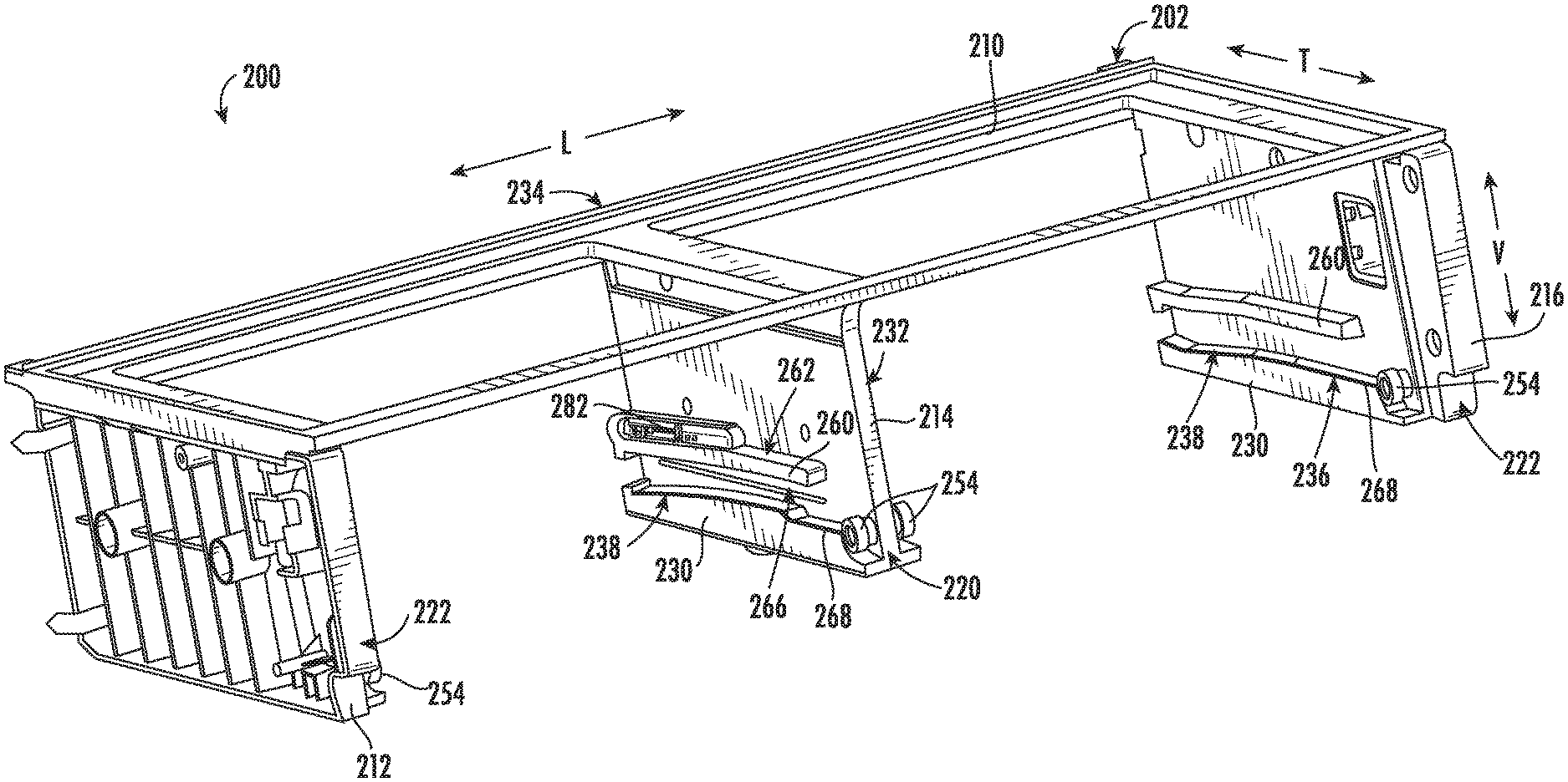
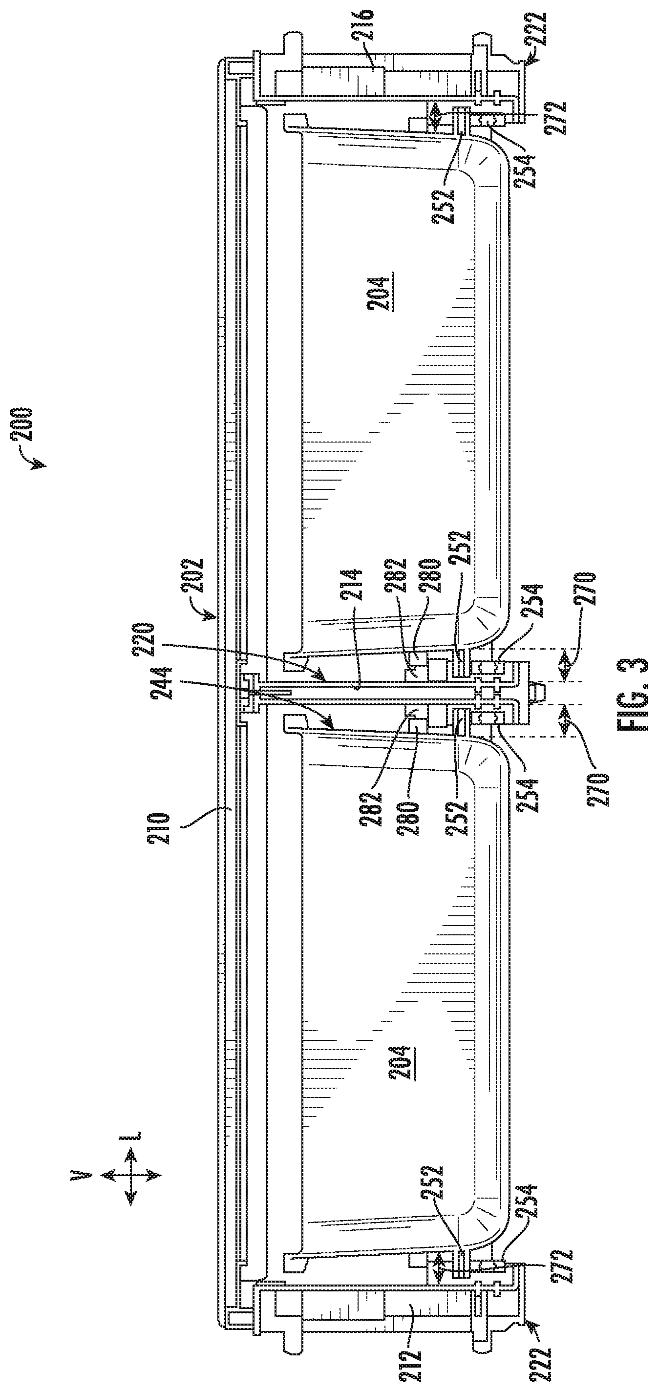
[0013] FIG. 3 provides a front view of a drawer assembly of the exemplary refrigerator appliance of FIG. 1 according to an exemplary embodiment of the present subject matter.
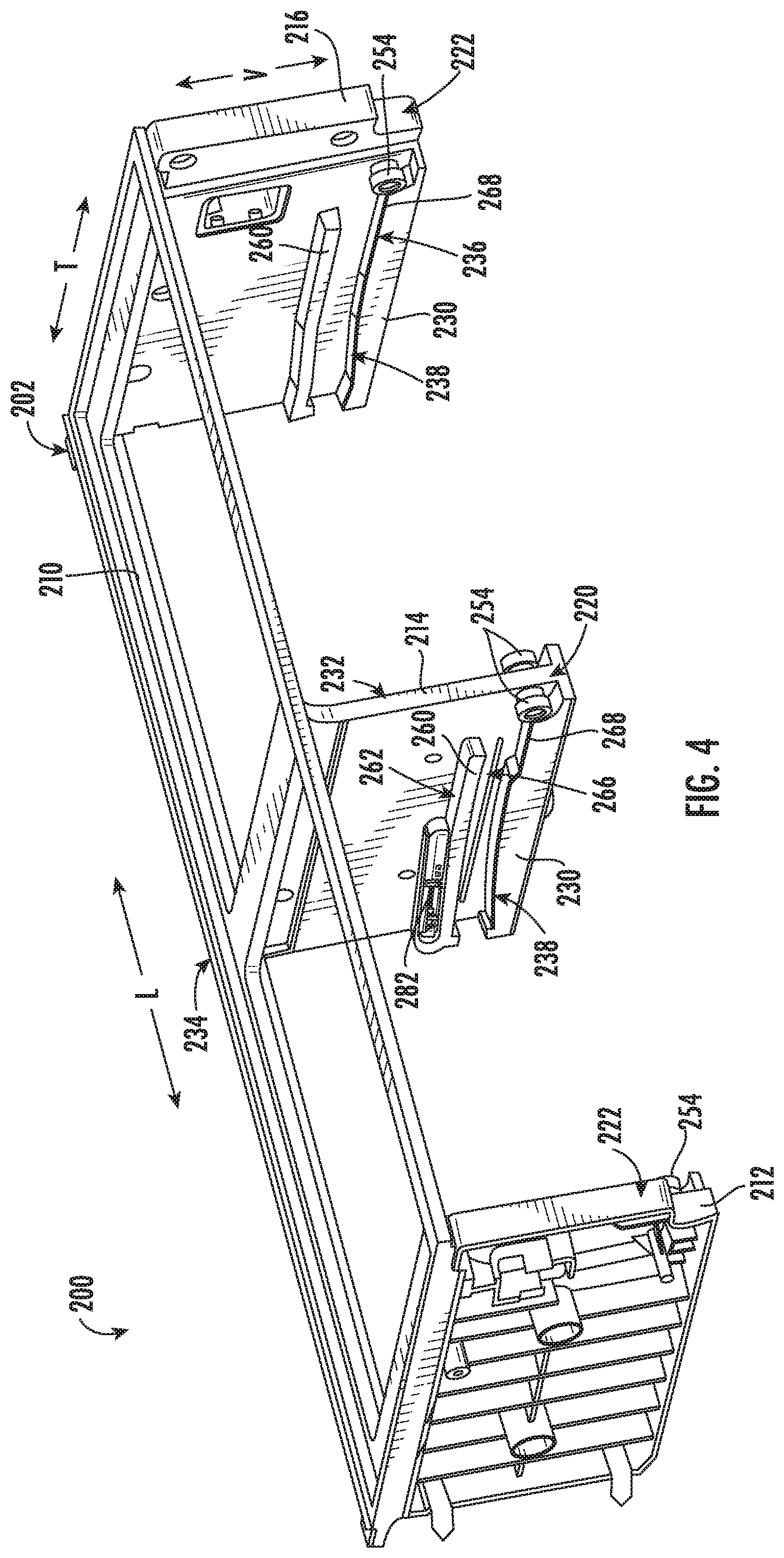
[0014] FIG. 4 provides a perspective view of the exemplary drawer assembly of FIG. 3 with the storage bins removed for clarity.
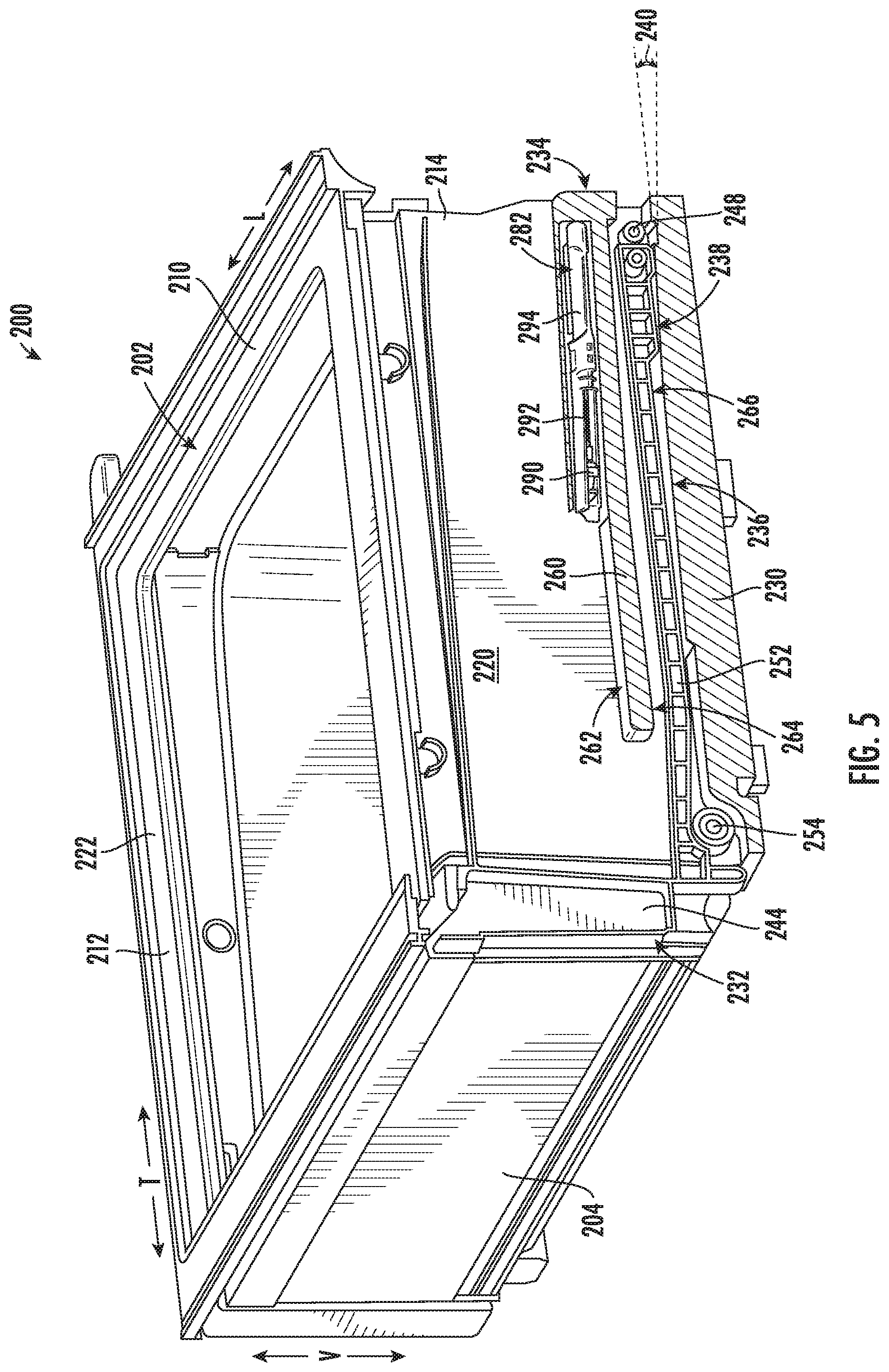
[0015] FIG. 5 provides a perspective cross sectional view of the exemplary drawer assembly of FIG. 3 according to an exemplary embodiment of the present subject matter.
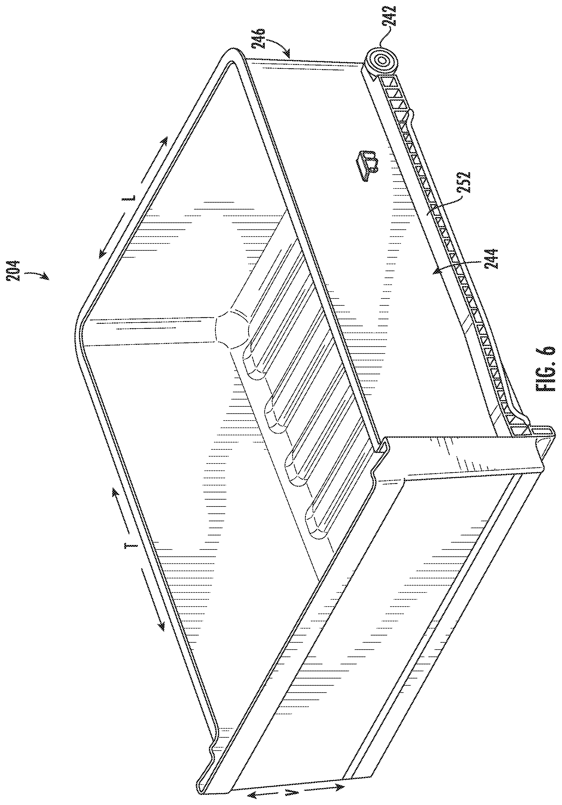
[0016] FIG. 6 is a perspective view of a storage bin of the exemplary drawer assembly of FIG. 3 according to an exemplary embodiment of the present subject matter.
[0017] FIG. 7 is a perspective view of a striker on the exemplary storage bin of FIG. 6 according to an exemplary embodiment of the present subject matter.
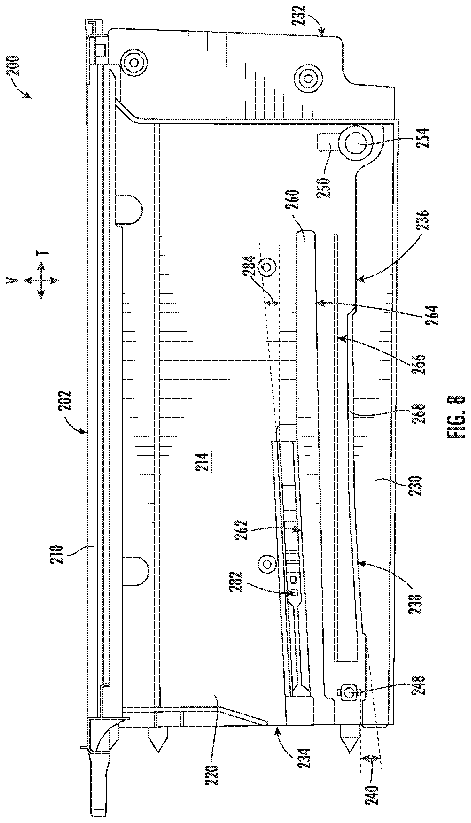
[0018] FIG. 8 is a side view of a center support of the exemplary drawer assembly of FIG. 3 according to an exemplary embodiment of the present subject matter.
[0019] FIG. 9 is a cross sectional view of the storage bin supported by a support roller of the exemplary drawer assembly of FIG. 3 according to an exemplary embodiment of the present subject matter.
[0020] FIG. 10 is a perspective view of a soft close mechanism in an extended position for use with the exemplary drawer assembly of FIG. 3 according to an exemplary embodiment of the present subject matter.
[0021] FIG. 11 is a perspective view of a soft close mechanism in a retracted position for use with the exemplary drawer assembly of FIG. 3 according to an exemplary embodiment of the present subject matter.
[0022] Repeat use of reference characters in the present specification and drawings is intended to represent the same or analogous features or elements of the present invention.
DETAILED DESCRIPTION
[0023] Reference now will be made in detail to embodiments of the invention, one or more examples of which are illustrated in the drawings. Each example is provided by way of explanation of the invention, not limitation of the invention. In fact, it will be apparent to those skilled in the art that various modifications and variations can be made in the present invention without departing from the scope or spirit of the invention. For instance, features illustrated or described as part of one embodiment can be used with another embodiment to yield a still further embodiment. Thus, it is intended that the present invention covers such modifications and variations as come within the scope of the appended claims and their equivalents.
[0024] FIG. 1 provides a perspective view of a refrigerator appliance 100 according to an exemplary embodiment of the present subject matter. Refrigerator appliance 100 includes a cabinet or housing 102 that extends between a top 104 and a bottom 106 along a vertical direction V, between a first side 108 and a second side 110 along a lateral direction L, and between a front side 112 and a rear side 114 along a transverse direction T. Each of the vertical direction V, lateral direction L, and transverse direction T are mutually perpendicular to one another, such that an orthogonal coordinate system is generally defined.
[0025] Housing 102 defines chilled chambers for receipt of food items for storage. In particular, housing 102 defines fresh food chamber 122 positioned at or adjacent top 104 of housing 102 and a freezer chamber 124 arranged at or adjacent bottom 106 of housing 102. As such, refrigerator appliance 100 is generally referred to as a bottom mount refrigerator. It is recognized, however, that the benefits of the present disclosure apply to other types and styles of refrigerator appliances such as, e.g., a top mount refrigerator appliance, a side-by-side style refrigerator appliance, or a single door refrigerator appliance. Moreover, aspects of the present subject matter may be applied to other appliances as well, such as ovens, storage cabinets, etc. Consequently, the description set forth herein is for illustrative purposes only and is not intended to be limiting in any aspect to any particular appliance or configuration.
[0026] Refrigerator doors 128 are rotatably hinged to an edge of housing 102 for selectively accessing fresh food chamber 122. In addition, a freezer door 130 is arranged below refrigerator doors 128 for selectively accessing freezer chamber 124. Freezer door 130 is coupled to a freezer drawer (not shown) slidably mounted within freezer chamber 124. Refrigerator doors 128 and freezer door 130 are shown in the closed configuration in FIG. 1. One skilled in the art will appreciate that other chamber and door configurations are possible and within the scope of the present invention.
[0027] FIG. 2 provides a perspective view of refrigerator appliance 100 shown with refrigerator doors 128 in the open position. As shown in FIG. 2, various storage components are mounted within fresh food chamber 122 to facilitate storage of food items therein as will be understood by those skilled in the art. In particular, the storage components may include bins 134 and shelves 136. Each of these storage components are configured for receipt of food items (e.g., beverages and/or solid food items) and may assist with organizing such food items. As illustrated, bins 134 may be mounted on refrigerator doors 128 or may slide into a receiving space in fresh food chamber 122. It should be appreciated that the illustrated storage components are used only for the purpose of explanation and that other storage components may be used and may have different sizes, shapes, and configurations.
[0028] Referring again to FIG. 1, a dispensing assembly 140 will be described according to exemplary embodiments of the present subject matter. Although several different exemplary embodiments of dispensing assembly 140 will be illustrated and described, similar reference numerals may be used to refer to similar components and features. Dispensing assembly 140 is generally configured for dispensing liquid water and/or ice. Although an exemplary dispensing assembly 140 is illustrated and described herein, it should be appreciated that variations and modifications may be made to dispensing assembly 140 while remaining within the present subject matter.
[0029] Dispensing assembly 140 and its various components may be positioned at least in part within a dispenser recess 142 defined on one of refrigerator doors 128. In this regard, dispenser recess 142 is defined on a front side 112 of refrigerator appliance 100 such that a user may operate dispensing assembly 140 without opening refrigerator door 128. In addition, dispenser recess 142 is positioned at a predetermined elevation convenient for a user to access ice and enabling the user to access ice without the need to bend-over. In the exemplary embodiment, dispenser recess 142 is positioned at a level that approximates the chest level of a user.
[0030] Dispensing assembly 140 includes an ice dispenser 144 including a discharging outlet 146 for discharging ice from dispensing assembly 140. An actuating mechanism 148, shown as a paddle, is mounted below discharging outlet 146 for operating ice or water dispenser 144. In alternative exemplary embodiments, any suitable actuating mechanism may be used to operate ice dispenser 144. For example, ice dispenser 144 can include a sensor (such as an ultrasonic sensor) or a button rather than the paddle. Discharging outlet 146 and actuating mechanism 148 are an external part of ice dispenser 144 and are mounted in dispenser recess 142. By contrast, refrigerator door 128 may define an icebox compartment 150 (FIG. 2) housing an icemaker and an ice storage bin (not shown) that are configured to supply ice to dispenser recess 142.
[0031] A control panel 152 is provided for controlling the mode of operation. For example, control panel 152 includes one or more selector inputs 154, such as knobs, buttons, touchscreen interfaces, etc., such as a water dispensing button and an ice-dispensing button, for selecting a desired mode of operation such as crushed or non-crushed ice. In addition, inputs 154 may be used to specify a fill volume or method of operating dispensing assembly 140. In this regard, inputs 154 may be in communication with a processing device or controller 156. Signals generated in controller 156 operate refrigerator appliance 100 and dispensing assembly 140 in response to selector inputs 154. Additionally, a display 158, such as an indicator light or a screen, may be provided on control panel 152. Display 158 may be in communication with controller 156, and may display information in response to signals from controller 156.
[0032] As used herein, "processing device" or "controller" may refer to one or more microprocessors or semiconductor devices and is not restricted necessarily to a single element. The processing device can be programmed to operate refrigerator appliance 100, dispensing assembly 140 and other components of refrigerator appliance 100. The processing device may include, or be associated with, one or more memory elements (e.g., non-transitory storage media). In some such embodiments, the memory elements include electrically erasable, programmable read only memory (EEPROM). Generally, the memory elements can store information accessible processing device, including instructions that can be executed by processing device. Optionally, the instructions can be software or any set of instructions and/or data that when executed by the processing device, cause the processing device to perform operations.
[0033] Referring now generally to FIGS. 3 through 11, a drawer assembly 200 which may be used with refrigerator appliance 100 will be described according to exemplary embodiments of the present subject matter. Specifically, drawer assembly 200 may be positioned within fresh food chamber 122 or freezer chamber 124 of refrigerator appliance 100, e.g., replacing one or more of bins 134 in FIG. 2. It should be appreciated that drawer assembly 200 is an exemplary embodiment of the present subject matter intended only for explaining aspects of the present subject matter and is not intended to limit the scope of the present subject matter in any manner.
[0034] As shown in FIGS. 3 and 4, drawer assembly 200 includes a drawer support frame 202 which is generally configured for supporting one or more storage bins 204, e.g., using a roller and guide rail assembly. More specifically, drawer support frame 202 includes a top frame 210, a left support wall 212, a center support wall 214, and a right support wall 216, each of which extend down from top frame 210. In general, top frame 210 may include a solid surface or pane of glass (not shown), is intended to form a top of each storage bin 204, and may additionally be used as a shelf within refrigerator appliance 100. Support walls 212-216 extend down from top frame 210 and are intended to support storage bins 204 while permitting a user to slide storage bins 204 between an open position to access food items positioned therein and a closed position when not in use or when doors 120 are closed.
[0035] Although the illustrated embodiment shows two storage bins 204 positioned adjacent each other along the lateral direction L, it should be appreciated that aspects the present subject matter may be applied to other drawer assembly styles and configurations. For example, drawer assembly 200 could instead include a single storage bin 204 or may include storage bins that are stacked adjacent each other along the vertical direction V. In addition, drawer support frame 202 and storage bins 204 may have any other suitable size or configuration. Moreover, it should be appreciated that drawer assembly 200 as described herein is designed such that storage bins 204 may be identical and interchangeable between the left hand and right hand side of drawer support frame 202.
[0036] According to exemplary embodiments, drawer assembly 200 and its components may be formed from any material which is sufficiently rigid to support the weight of storage bins 204 or other supported items. For example, drawer support frame 202 and storage bins 204 may be formed by injection molding, e.g., using a suitable plastic material, such as injection molding grade high impact polystyrene (HIPS) or acrylonitrile butadiene styrene (ABS). Alternatively, according to the exemplary embodiment, these components may be compression molded, e.g., using sheet molding compound (SMC) thermoset plastic. According still other embodiments, some or all of drawer support frame 202 and storage bins 204 may be formed from stamped metal, acrylic glass, or any other suitable material or combination thereof.
[0037] Although FIGS. 3 and 4 illustrate drawer assembly 200 as having two storage bins positioned adjacent each other, exemplary embodiments of the present subject matter include a single storage bin configuration. For example, referring now also to FIGS. 5 through 11, such a single storage bin configuration will be described according to an exemplary embodiment of the present subject matter. In this regard, drawer support frame 202 will be described as including a first side support 220 and a second side support 222 which are spaced apart along the transverse direction T for receiving storage bin 204. It should be appreciated that first side support 220 may generally correspond with center support wall 214 and a second side support 222 may generally correspond with either left support wall 212 or right support wall 216 as shown in FIGS. 3 and 4. In addition, it should be appreciated that according to alternative embodiments, second side support 222 may be defined by a sidewall of fresh food compartment 122 instead of extending vertically from top frame 210.
[0038] As mentioned above, storage bin 204 is supported by first side support 220 and second side support 222 such that is movable between an open or extended position and a closed or retracted position. Specifically, in order to reduce costs associated with expensive ball bearings slide assemblies, storage bin 204 may be supported by a roller and guide rail assembly. Specifically, first side support 220 may define a support rail 230 which protrudes or extends from the first side support 220 toward storage bin 204, e.g., along the lateral direction L. In addition, support rail 230 generally extends along substantially an entire depth of drawer support frame 202, e.g., from a front 232 of drawer support frame 202 to a rear 234 of drawer support frame 202 along the transverse direction T. It should be appreciated that as used herein, terms of approximation, such as "approximately," "substantially," or "about," refer to being within a ten percent margin of error.
[0039] Generally speaking, support rail 230 may have any suitable shape or profile suitable for facilitating the opening and closing of storage bin 204. For example, support rail 230 may include a flat portion 236 which extends substantially parallel to the transverse direction T and an angled portion 238 which is angled relative to the transverse direction T at a guide angle 240. In this manner, flat portion 236 may be defined proximate a front 232 of support frame 202 such that storage bin 204 extends substantially within a horizontal plane as it approaches the open position. By contrast, angled portion 238 may be designed to facilitate closing of storage bin 204 by encouraging storage bin 204 to roll down on angled portion 238 under the force of gravity as it approaches the closed position.
[0040] In addition, the guide rail and roller assembly may further include a bin roller 242 which is rotatably mounted on a side 244 of storage bin 204 for rolling along support rail 230 as storage bin 204 moves between the open position and the closed position. More specifically, bin roller 242 may be mounted proximate a rear 246 of storage bin 204. Notably, drawer assembly 200 may further include a rear stop 248 positioned proximate rear 234 of support frame 202 and a front stop 250 positioned proximate front 232 of support frame 202. In this manner, bin roller 242 may be configured for engaging or seating against rear stop 248 when in the fully closed position and may be prevented from pulling out of support frame 202 by front stop 250 when in the fully extended or open position.
[0041] In addition, side 244 of storage bin 204 may define a bin guide rail 252 that protrudes toward first side support 220, e.g., substantially along the lateral direction L. A support roller 254 may be rotatably mounted to first side support 220 proximate front 232 of support frame 202 for supporting bin guide rails 252 as storage bin 204 moves between the open position and the closed position. It should be appreciated that a similar guide rail and roller assembly may be included proximate a second side support 222. In this manner, storage bin 204 is fully supported along the lateral direction L and the transverse direction T. Specifically, support roller 254 supports bin guide rail 252 proximate front 232 of storage bin 204 and support rail 230 support bin roller 242 proximate rear 234 of storage bin 204.
[0042] As best shown in FIG. 8, drawer assembly 200 may further include an upper rail 260 that is defined by first side support 220 and defines a top surface 262 and a bottom surface 264. As shown, upper rail 260 is spaced apart from and extends parallel to support rail 230 to define a roller slot 266. More specifically, roller slot 266 is defined between a top surface of support rail 230 and bottom surface 264 of upper rail 260. Bin roller 242 may be received within roller slot 266 to prevent too much wobble or vertical movement of storage bin 204 within roller slot 266. In addition, a distal end of one or both of support rail 230 and upper rail 260, a retention lip 268 may be defined for retaining bin roller 242 within roller slot 266.
[0043] Notably, when storage bin 204 is installed within drawer support frame by the roller and guide rail assembly, gaps are defined between storage bin 204 and side supports 220-222. Specifically, a first gap 270 is defined between storage bin 204 and first side support 220 along the lateral direction L and a second gap 272 is defined between storage bin 204 and second side support 222 along the lateral direction L. According to exemplary embodiments, first gap 270 is smaller than second gap 272. For example, according to an exemplary embodiment, first gap 270 may be less than about 0.1 millimeters less than about 0.075 millimeters, or smaller. By contrast, second gap 272 may be greater than 1 mm, greater than 2 millimeters, or larger. In this regard, for example, the support rail 230 and bin guide rail 252 may be wider to support the lateral variation of storage bin 204 within support frame 202 proximate second side support 222. By contrast, retention lip 268 is configured for slidably receiving and retaining bin roller 242 proximate first side support 220, thereby substantially fixing its lateral position. It should be appreciated that the guide rail and roller assembly as described herein may vary according to alternative embodiments, and such variations remain within the scope of the present subject matter.
[0044] Referring still to FIGS. 3 through 11, assembly 200 may further include a striker 280 which extends from side 244 of storage bin 204 toward first side support 220. In addition, drawer assembly 200 may include a soft close mechanism 282 which is mounted to the first side support 220 and is configured for engaging striker 280 when storage bin 204 is moved toward the closed position. However, it should be appreciated that according to alternative embodiments, the position of striker 280 and soft close mechanism 282 may be reversed. Specifically, for example, striker 280 may extend from first side support 220 and soft close mechanism 282 may be mounted on storage bin 204.
[0045] As used herein, soft close mechanism is intended to refer to devices, mechanisms, or assemblies which are designed to act as a damper to slow the velocity of the closing drawer or storage bin while also engaging the storage bin and moving it into a fully closed position. According to the illustrated embodiment, soft close mechanism 282 is mounted to top surface 262 of upper rail 260 and is mounted at an extension angle 284 relative to the transverse direction T. In addition, extension angle 284 is substantially equivalent to guide angle 240 such that soft close mechanism 282 will remain engaged with striker 280 as storage bin 204 moves toward the closed position.
[0046] Referring now specifically to FIGS. 7, 10, and 11, the manner in which an soft close mechanism 282 engages striker 280 to facilitate a soft close operation of storage bin 204 will be described according to an exemplary embodiment of the present subject matter. As shown, striker 280 generally defines a rear face or striking face 286 and a front face or locking face 288. In addition, soft close mechanism 282 defines a pivoting head 290 mounted on the distal end of a piston rod 292. Piston rod 292 is slidable along the transverse direction T within a cylinder assembly 294 which provides the damping and retraction forces to piston rod 292.
[0047] Thus, during operation, as storage bin 204 is moved toward the closed position, striking face 286 of striker 280 impacts a first face 296 of pivoting head 290. As storage bin 204 continues to move toward the closed position, pivoting head 290 pivots relative to piston rod 292 such that a second face 298 of pivoting head 290 engages locking face 288 of striker 280. At this point, striking face 286 and locking face 288 of striker 280 are sandwiched between first face 296 and second face 298 of pivoting head 290 such that storage bin 204 moves with pivoting head 290 along the transverse direction T. Through this linkage, cylinder assembly 294 may act to damp the closing motion of storage bin 204 via piston rod 292. Simultaneously, cylinder assembly 294 may draw storage bin 204 into the fully closed position.
[0048] When a user desires to open storage bin 204, they may pull on a handle at the front of storage bin 204 such that locking face 288 of striker 280 pulls against second face 298 of pivoting head 290 and extends piston rod 292 within cylinder assembly 294. After piston rod 292 has reached its full extension, the force of locking face 288 against second face 298 forces pivoting head 290 to pivot away from and release striker 280 altogether. Piston rod 292 may be configured for remaining in the extended position until a subsequent closing process of storage bin 204. It should be appreciated that the soft close mechanism described is only exemplary and that other soft close mechanisms may be used according to alternative embodiments.
[0049] This written description uses examples to disclose the invention, including the best mode, and also to enable any person skilled in the art to practice the invention, including making and using any devices or systems and performing any incorporated methods. The patentable scope of the invention is defined by the claims, and may include other examples that occur to those skilled in the art. Such other examples are intended to be within the scope of the claims if they include structural elements that do not differ from the literal language of the claims, or if they include equivalent structural elements with insubstantial differences from the literal languages of the claims.
* * * * *
D00000
D00001
D00002
D00003
D00004
D00005
D00006
D00007
D00008
D00009
D00010
XML
uspto.report is an independent third-party trademark research tool that is not affiliated, endorsed, or sponsored by the United States Patent and Trademark Office (USPTO) or any other governmental organization. The information provided by uspto.report is based on publicly available data at the time of writing and is intended for informational purposes only.
While we strive to provide accurate and up-to-date information, we do not guarantee the accuracy, completeness, reliability, or suitability of the information displayed on this site. The use of this site is at your own risk. Any reliance you place on such information is therefore strictly at your own risk.
All official trademark data, including owner information, should be verified by visiting the official USPTO website at www.uspto.gov. This site is not intended to replace professional legal advice and should not be used as a substitute for consulting with a legal professional who is knowledgeable about trademark law.