Axial Flow Pump
KECK; BENJAMIN
U.S. patent application number 16/641366 was filed with the patent office on 2020-07-16 for axial flow pump. The applicant listed for this patent is VOITH PATENT GMBH. Invention is credited to BENJAMIN KECK.
| Application Number | 20200224666 16/641366 |
| Document ID | / |
| Family ID | 63311995 |
| Filed Date | 2020-07-16 |


| United States Patent Application | 20200224666 |
| Kind Code | A1 |
| KECK; BENJAMIN | July 16, 2020 |
AXIAL FLOW PUMP
Abstract
An axial flow pump for pumping a liquid has a motor. The motor of the pump is arranged such that the liquid to be pumped flows around the motor. No elaborate rotary leadthroughs of the pump shaft through the pipe system are needed. Furthermore, the bearings of the motor are lubricated by the liquid to be pumped, thereby avoiding risky oil lubrication. As a result, the axial flow pump is suitable for use in drinking water pipelines.
| Inventors: | KECK; BENJAMIN; (HEIDENHEIM, DE) | ||||||||||
| Applicant: |
|
||||||||||
|---|---|---|---|---|---|---|---|---|---|---|---|
| Family ID: | 63311995 | ||||||||||
| Appl. No.: | 16/641366 | ||||||||||
| Filed: | August 14, 2018 | ||||||||||
| PCT Filed: | August 14, 2018 | ||||||||||
| PCT NO: | PCT/EP2018/071994 | ||||||||||
| 371 Date: | February 24, 2020 |
| Current U.S. Class: | 1/1 |
| Current CPC Class: | F04D 29/548 20130101; F04D 13/06 20130101; F04D 3/005 20130101; F04D 29/528 20130101; F04D 29/181 20130101; F04D 13/0653 20130101; F04D 29/046 20130101; F04D 29/061 20130101 |
| International Class: | F04D 29/18 20060101 F04D029/18; F04D 29/046 20060101 F04D029/046 |
Foreign Application Data
| Date | Code | Application Number |
|---|---|---|
| Aug 23, 2017 | DE | 10 2017 119 241.7 |
Claims
1-11. (canceled)
12. An axial flow pump for pumping a liquid, the axial flow pump comprising: a rotatably mounted runner having a hub and a multiplicity of runner blades connected to said hub; a motor encased in a motor housing, said motor having a rotor; a tubular pump housing formed with a runner chamber, a first opening for receiving the liquid to be pumped, and a second opening for discharging the liquid to be pumped, wherein said runner chamber is wrapped around said runner, said first opening is arranged near said runner, and said second opening is arranged near said motor; said motor being connected to said runner for driving said runner, said motor together with said runner forming a unit, and said motor including a combined track-and-guide bearing arranged between said runner and said rotor, and a guide bearing arranged at an end of said motor housing opposite said runner; said motor being disposed within an area of the pump through which the liquid flows during pump operation; a plurality of cross members configured to maintain said unit formed of said motor and said runner centered in said pump housing, said cross members being configured to reduce a swirl of the liquid passing said runner during pump operation; and wherein said motor housing is filled and flowed around with the liquid during pump operation so that the liquid may lubricate said track-and-guide bearings and said guide bearing.
13. The axial flow pump according to claim 12, wherein said runner blades are rigidly connected with said hub.
14. The axial flow pump according to claim 12, wherein said runner blades are rotatably mounted and connected to said hub.
15. The axial flow pump according to claim 12, wherein said runner chamber has a cylindrical shape.
16. The axial flow pump according to claim 12, wherein said runner chamber is ball-shaped and divided into sections.
17. The axial flow pump according to claim 12, wherein said pump housing is formed with openings having a circular cross-section.
18. The axial flow pump according to claim 12, wherein said motor is configured to be able to drive said runner at a constant speed.
19. The axial flow pump according to claim 12, wherein said motor is configured to be able to drive said runner at variable speed.
20. The axial flow pump according to claim 12, wherein said pump housing comprises supports configured to support the pump on the ground.
21. The axial flow pump according to claim 12, wherein said pump housing comprises suspension supports for suspending the pump from a support structure.
22. The axial flow pump according to claim 12, wherein the pump is configured to pump drinking water as the liquid.
Description
[0001] The present invention relates to an axial flow pump for installation in a pipe or tunnel system.
[0002] The axial flow pumps known from the prior art are characterized in that the drive of the pump runner is arranged outside the water-carrying area. Such an axial flow pump is set forth for example in CH 150076. Such a pump requires a sealed leadthrough of the pump shaft and an angular gear or an arc-shaped arrangement of the water-carrying part of the pump.
[0003] The object of this invention is to specify an axial flow pump that may be integrated into an existing pipe or tunnel system without major structural changes to the existing structure. In addition, the axial flow pump according to the invention is low-maintenance and environmentally friendly, because the axial flow pump according to the invention is free of substances that cause water pollution.
[0004] The inventor has found that this object may be accomplished by an axial flow pump with the features of Claim 1. Advantageous embodiments are set forth in the dependent claims that depend from Claim 1.
[0005] The solution according to the invention is explained below with reference to the drawings. The drawings illustrate the following:
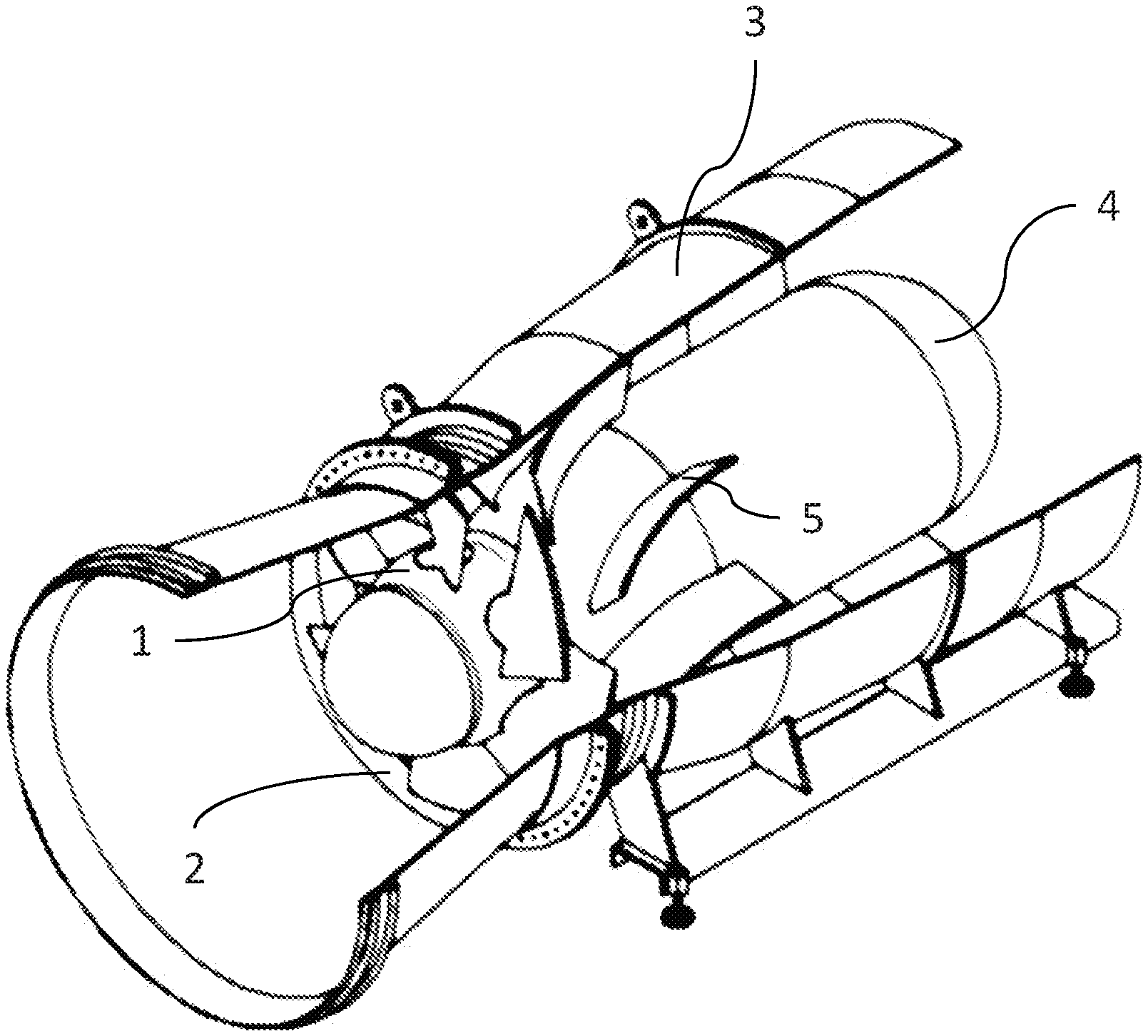
[0006] FIG. 1 Axial flow pump according to the invention;
[0007] FIG. 2 Cross-section of axial flow pump according to the invention;
[0008] FIG. 1 shows an axial flow pump according to the invention. The pump housing, marked 3, is cut away to show the pump below. The pump comprises an runner marked 1. The runner 1 is arranged inside an runner chamber that wraps around it, marked 2. The runner chamber 2 is part of the pump housing and may be spherical or cylindrical in shape. In the first case, the runner chamber 2 is divided into sections. The pump further comprises a motor, which is marked 4 and enclosed by a motor housing. The runner 1 is connected to the motor 4 in such a way that the motor may drive it; it comprises a hub and a multiplicity of blades. The runner blades may be rigidly or rotatably mounted and connected to the hub of the runner 1. The motor 4 may be designed to rotate at constant or variable speed. The unit, consisting of the motor 4 and runner 1, is held centrally in the pump housing 3 by a multiplicity of cross members, one of which is marked 5. The pump housing 3, which wraps around the pump, is substantially tubular in shape, although the diameter of these tubes need not be constant, and has a first opening, located near the runner 1, for receiving the pumped liquid, and a second opening, located near the motor 4, for discharging the pumped liquid. The cross members 5 are supported, on the outside on the pump housing 3 and on the inside on the motor housing. The liquid entering the pump from the first opening during operation is imparted with a certain amount of swirl as it passes the runner. The cross members are designed in such a way that they may reduce the swirl of the liquid. During operation, the pumped liquid flows around the motor housing. The two openings of the pump housing 3 may be circular, which makes it easier to integrate the axial pump into an existing pipe system. In other installation situations, however, the openings may also have other cross-sectional shapes. The pump housing 3 may have devices to support the pump on the ground or to suspend the pump from suitable support structures.
[0009] FIG. 3 shows a longitudinal section of an axial flow pump according to the invention, permitting a view into the motor housing. The motor 4 has two bearings. A first bearing, marked 61, is designed as a combined track and guide bearing and is arranged between the runner 1 and the rotor of the motor 4. A second bearing, marked 62, is designed as a guide bearing and is arranged at the end of the motor housing facing away from the runner 1. Both bearings 61 and 62 are lubricated by the pumped liquid, which is made possible by the fact that the motor housing is not sealed against the liquid that flows around the motor housing, so that the pumped liquid fills the motor housing. As a result, lubrication by oil, which could potentially contaminate the pumped liquid, is avoided. Consequently, the axial pipe pump according to the invention may also be used to pump drinking water.
[0010] Because the motor 4, which drives the runner 1, is arranged within the liquid-carrying area, there is no need for an outward-fed pump shaft and the associated sealing of the rotary leadthrough. Only the control and power cables need to be fed to the exterior. In addition, a curved arrangement of the liquid-carrying part of the pump is not required, and consequently the pump according to the invention is much smaller and more compact than comparable classic axial pumps. The pump according to the invention may thus be easily integrated into an existing pipe or tunnel system without major structural changes. As a result of lubrication using the pumped liquid, the pump is largely maintenance-free and environmentally friendly. In the event of maintenance, the entire pump may be removed in one piece or in parts and overhauled.
[0011] Depending on the use case, the pump according to the invention may be installed at any angle in an existing or new pipe or tunnel system. The liquid inlet and outlet of the axial flow pump may be adapted according to the use case (flange connection, direct connection to the existing pipe or tunnel system, etc.).
[0012] One possible application of the axial flow pump according to the invention is the installation of a horizontal version of the pump in a drinking water pumping station to increase the suction pressure of the main pumps.
* * * * *
D00000
D00001
D00002
XML
uspto.report is an independent third-party trademark research tool that is not affiliated, endorsed, or sponsored by the United States Patent and Trademark Office (USPTO) or any other governmental organization. The information provided by uspto.report is based on publicly available data at the time of writing and is intended for informational purposes only.
While we strive to provide accurate and up-to-date information, we do not guarantee the accuracy, completeness, reliability, or suitability of the information displayed on this site. The use of this site is at your own risk. Any reliance you place on such information is therefore strictly at your own risk.
All official trademark data, including owner information, should be verified by visiting the official USPTO website at www.uspto.gov. This site is not intended to replace professional legal advice and should not be used as a substitute for consulting with a legal professional who is knowledgeable about trademark law.