Electric Compressor
YOO; Byungkil ; et al.
U.S. patent application number 16/735811 was filed with the patent office on 2020-07-16 for electric compressor. This patent application is currently assigned to LG ELECTRONICS INC.. The applicant listed for this patent is LG ELECTRONICS INC.. Invention is credited to Yongkyu CHOI, Kyoungjun PARK, Sanghun SEONG, Byungkil YOO.
| Application Number | 20200224659 16/735811 |
| Document ID | / |
| Family ID | 71517557 |
| Filed Date | 2020-07-16 |


| United States Patent Application | 20200224659 |
| Kind Code | A1 |
| YOO; Byungkil ; et al. | July 16, 2020 |
ELECTRIC COMPRESSOR
Abstract
A compressor includes a main housing having an internal space, a motor provided in the main housing and comprising a stator and a rotor, a shaft coupled to the rotor, and a shaft mounting portion provided at one end of the shaft and having a smaller diameter than the shaft. A sub-ball bearing is coupled to the shaft mounting portion, and a fixing latch is coupled to the shaft mounting portion. The fixing latch includes a latching portion configured to constrain the sub-ball bearing in the shaft mounting portion.
| Inventors: | YOO; Byungkil; (Seoul, KR) ; PARK; Kyoungjun; (Seoul, KR) ; CHOI; Yongkyu; (Seoul, KR) ; SEONG; Sanghun; (Seoul, KR) | ||||||||||
| Applicant: |
|
||||||||||
|---|---|---|---|---|---|---|---|---|---|---|---|
| Assignee: | LG ELECTRONICS INC. Seoul KR |
||||||||||
| Family ID: | 71517557 | ||||||||||
| Appl. No.: | 16/735811 | ||||||||||
| Filed: | January 7, 2020 |
| Current U.S. Class: | 1/1 |
| Current CPC Class: | F04C 29/023 20130101; F04C 29/0078 20130101; F04C 23/008 20130101; F04C 18/0215 20130101 |
| International Class: | F04C 18/02 20060101 F04C018/02; F04C 29/02 20060101 F04C029/02; F04C 23/00 20060101 F04C023/00; F04C 29/00 20060101 F04C029/00 |
Foreign Application Data
| Date | Code | Application Number |
|---|---|---|
| Jan 11, 2019 | KR | 10-2019-0003810 |
Claims
1. A compressor comprising: a main housing defining an internal space; a motor disposed in the main housing and comprising a stator and a rotor; a shaft coupled to the rotor; a shaft mounting portion formed at one end of the shaft and having a smaller diameter than remaining portions of the shaft; a sub-ball bearing coupled to the shaft mounting portion; and a fixing latch coupled to the shaft mounting portion and comprising a latching portion configured to constrain the sub-ball bearing on the shaft mounting portion.
2. The compressor of claim 1, wherein the fixing latch includes two or more latching portions and a supporting portion that is connected to the two or more latching portions.
3. The compressor of claim 2, wherein the supporting portion comprises a portion that is forwardly extended from the latching portion toward the shaft mounting portion.
4. The compressor of claim 3, wherein the fixing latch includes a plurality of latching portions and a plurality of supporting portions forwardly extended from respective ones of the latching portions, and the plurality of supporting portions being connected with each other in front areas of the latching portions.
5. The compressor of claim 2, wherein the supporting portion comprises a coupling hole configured for receiving a fastener to couple the supporting portion to the shaft mounting portion.
6. The compressor of claim 2, wherein the shaft mounting portion comprises a hollow portion, and the fixing latch is inserted into the hollow portion.
7. The compressor of claim 6, wherein the shaft mounting portion comprises an opening extending radially outward through the shaft mounting portion from the hollow portion and configured to couple with a latching portion of the fixing latch.
8. The compressor of claim 7, wherein the length and the width of the latching portion are equal to the length and the width of the opening, and a predetermined area of the latching portion is configured to project through the opening and extend radially outward from the shaft mounting portion.
9. The compressor of claim 1, wherein an upper area of the latching portion is downwardly inclined from a front side of the latching portion to a rear side of the latching portion.
10. The compressor of claim 8, wherein a front side of the latching portion is higher than the opening and a rear side of the latching portion is as high as the opening.
11. The compressor of claim 1, wherein the opposite end of the shaft is rotatably supported by a journal bearing.
12. The compressor of claim 1, wherein the fixing latch has elasticity.
13. A compressor comprising: a main housing defining an internal space; a motor disposed in the main housing and comprising a stator and a rotor; a shaft coupled to the rotor; a shaft mounting portion formed at one end of the shaft and having a smaller diameter than remaining portions of the shaft; a sub-ball bearing coupled to the shaft mounting portion; a hollow portion defined in the shaft mounting portion; and a fixing latch comprising a latching portion and a supporting portion connected to the latching portion, wherein one side of the latching portion contacts an edge of the sub-ball bearing and one side of the supporting portion opposite from a side of the supporting portion connected with the latching portion is inserted in the hollow portion.
14. The compressor of claim 13, wherein the latching portion is downwardly inclined from a front side of the latching portion to a rear side of the latching portion.
15. The compressor of claim 13, wherein the fixing latch includes two or more latching portions and a supporting portion that is connected to the two or more latching portions.
16. The compressor of claim 15, wherein the supporting portion comprises an area that is forwardly extended from the latching portion.
17. A compressor comprising: a main housing defining an internal space; a motor disposed in the main housing and comprising a stator and a rotor; a shaft coupled to the rotor; a shaft mounting portion formed at one end of the shaft and having a smaller diameter than remaining portions of the shaft; a sub-ball bearing coupled to the shaft mounting portion; a hollow portion defined in the shaft mounting portion; and a fixing latch comprising a latching portion and a supporting portion connected to the latching portion, wherein one side of the latching portion contacts an edge of the sub-ball bearing and one side of the supporting portion opposite from a side of the supporting portion connected with the latching portion is coupled to an outer surface of the shaft mounting portion.
18. The compressor of claim 17, wherein the latching portion is downwardly inclined from a front side of the latching portion to a rear side of the latching portion.
19. The compressor of claim 17, wherein the fixing latch comprises two or more latching portions and a supporting portion that is connected to the two or more latching portions.
20. The compressor of claim 19, wherein the supporting portion comprises an area that is forwardly extended from the latching portion.
Description
CROSS-REFERENCE TO RELATED APPLICATIONS
[0001] This application claims priority to Korean Patent Application No. 10-2019-0003810 filed on Jan. 11, 2019 in Korea, the entire contents of which is hereby incorporated by reference in its entirety.
BACKGROUND OF THE DISCLOSURE
Field of the Disclosure
[0002] Embodiments of the present disclosure relate to an electric compressor, more particularly, a scroll compressor.
Background of the Disclosure
[0003] A compressor is a device that is configured to compress a fluid (e.g., a refrigerant) by means of an electric energy. Examples of such a scroll compressor include a scroll compressor. The scroll compressor may gain a relatively high compression ratio, compared with other types of compressors. In addition, processes of fluid suction, compression and discharge are performed smoothly and gently in the scroll compressor so as to gain a stable torque. Accordingly, the scroll compressor has been used in compressing a refrigerant for an air conditioner broadly.
[0004] The scroll compressor may include a motor part and a scroll part as a compression configuration and an inverter part for controlling the motor part. The motor part may include a stator and a rotor. The scroll part may include a fixed scroll and an orbiting scroll.
[0005] A crank shaft (hereinafter, `the shaft`) is coupled to the rotor of the motor and the orbiting scroll is driven by means of the shaft. While the orbiting scroll is orbiting while engaging with the fixed scroll, a fluid (e.g., a refrigerant) is compressed. The shaft is supported by a bearing to reduce a frictional resistance, because it is rotary. A ball bearing and/or a journal bearing may be used as the above-noted bearing.
[0006] Meanwhile, the drive or operation of the compressor is likely to cause horizontal vibration. Such horizontal vibration might move the shaft of the compressor in a horizontal direction. However, if moved in the horizontal direction, the shaft is likely to collide against other components that are arranged nearby enough to cause damage. Accordingly, the horizontal-direction movement of the shaft has to be prevented during the drive or operation of the compressor. Especially, vibration occurs during the drive in case of a scroll compressor for a vehicle such that the horizontal-direction movement of the shaft should be prevented.
[0007] A conventional method for preventing such the horizontal-direction movement of the shaft in the conventional compressor is as follows.
[0008] U.S. Pat. No. 8,202,071 discloses a method in that the shaft of the compressor is pressed in a main ball bearing to prevent the horizontal-direction movement of the shaft. Under such a structure, an outer race of a main ball bearing is insertedly pressed to a main frame and an inner race of the main ball bearing is insertedly pressed to a shaft. As the shaft is pressed and inserted in the main ball bearing, the horizontal-direction movement of the shaft is constrained by the main ball bearing. Accordingly, even if the horizontal-direction movement occurs in the compressor, the shaft will not be moved horizontally.
[0009] Meanwhile, there is another structure configured to use a journal bearing as the main bearing and a sub-ball bearing that is arranged opposite to the journal bearing (hereinafter, the sub-ball bearing structure). Under the sub-ball bearing structure, the horizontal-direction movement is not constrained. The reason why is as follows.
[0010] The shaft is not pressedly inserted in the journal bearing. The shaft is not pressedly inserted in an inner race of the sub-ball bearing but slidingly coupled thereto based on an assembling process of the compressor. Accordingly, the shaft is assembled to the journal bearing and the sub-ball bearing, with a preset tolerance, so as not to constrain the horizontal-direction movement of the shaft.
[0011] As mentioned above, the vibration occurring during the drive or operation of the sub-ball bearing compressor might move in the horizontal direction enough to collide against the components arranged nearby and cause damage. Accordingly, there are demands for preventing the shaft from being horizontally moved by such vibration.
SUMMARY OF THE DISCLOSURE
[0012] Accordingly, an object of the present disclosure is to address the above-noted and other problems.
[0013] Another object of the present disclosure is to provide a compressor that may prevent a shaft from being horizontally moved in a sub-ball bearing structure.
[0014] Another object of the present disclosure is to provide a compressor that may prevent the shaft from being horizontally moved, even without pressedly inserting the shaft in a ball bearing.
[0015] Embodiments of the present disclosure may provide a compressor comprising a main housing having an internal space; a motor provided in the main housing and comprising a stator and a rotor; a shaft coupled to the rotor; a shaft mounting portion provided at one end of the shaft and having a smaller diameter than the shaft; a sub-ball bearing slidingly coupled to the shaft mounting portion; and a fixing latch coupled to the shaft mounting portion and comprising a latching portion configured to constrain the sub-ball bearing on the shaft mounting portion.
[0016] Two or more latching portions may be provided and the fixing latch comprises a supporting portion that is connected to the two or more latching portions.
[0017] The length and the width of the latching portion may be equal to the length and the width of the opening, and at least a predetermined area of the latching portion may be projectedly exposed to the opening.
[0018] The front side of the latching portion may be higher than the opening and the rear side of the latching portion may be as high as the opening.
[0019] The supporting portion may comprise an area that is forwardly extended from the latching portion. A plurality of latching portions may be provided and a plurality of supporting portions forwardly extended from the latching portions, respectively, may be provided, and the plurality of the supporting portions may be connected with each other in front areas of the latching portions.
[0020] The supporting portion may comprise a coupling hole provided to couple the supporting portion to the shaft mounting portion.
[0021] The shaft mounting portion may comprise a hollow portion to which the fixing latch is coupled.
[0022] The shaft mounting portion may comprise an opening formed to couple the supporting portion thereto.
[0023] The other end of the shaft may be rotatably supported by a journal bearing.
[0024] Embodiments of the present disclosure may also provide a compressor comprising a main housing having an internal space; a motor provided in the main housing and comprising a stator and a rotor; a shaft coupled to the rotor; a shaft mounting portion provided at one end of the shaft and having a smaller diameter than the shaft; a sub-ball bearing slidingly coupled to the shaft mounting portion; a hollow portion provided in the shaft mounting portion; and a fixing latch comprising a latching portion and a supporting portion connected to the latching portion, wherein one side of the latching portion contacts with the sub-ball bearing and further wherein one side of the supporting portion is connected with the latching portion and the other side is inserted in the hollow portion.
[0025] The latching portion may be downwardly inclined from a front side to a rear side.
[0026] Embodiments of the present disclosure may also provide a compressor comprising a main housing having an internal space; a motor provided in the main housing and comprising a stator and a rotor; a shaft coupled to the rotor; a shaft mounting portion provided at one end of the shaft and having a smaller diameter than the shaft; a sub-ball bearing slidingly coupled to the shaft mounting portion; a hollow portion provided in the shaft mounting portion; and a fixing latch comprising a latching portion and a supporting portion connected to the latching portion, wherein one side of the latching portion contacts with the sub-ball bearing and further wherein one side of the supporting portion is connected with the latching portion and the other side is coupled to an outer surface of the shaft mounting portion.
[0027] The latching portion may be downwardly inclined from a front side to a rear side.
[0028] Further aspects of this disclosure will become apparent from the detailed description given hereinafter. However, it should be understood that the detailed description and specific examples, while indicating preferred embodiments of the disclosure, are given by illustration only, since various changes and modifications within the spirit and scope of the disclosure will become apparent to those skilled in the art from this detailed description.
BRIEF DESCRIPTION OF THE DRAWINGS
[0029] The present invention will become more fully understood from the detailed description given herein below and the accompanying drawings, which are given by illustration only, and thus are not limitative of the present invention, and wherein:
[0030] FIG. 1 is a sectional diagram illustrating an entire structure of a compressor according to one embodiment of the present disclosure;
[0031] FIG. 2 is a sectional diagram illustrating the embodiment of the compressor;
[0032] FIG. 3 is an exploded perspective diagram of FIG. 2;
[0033] FIG. 4 is a sectional diagram illustrating an assembly process of FIG. 2;
[0034] FIG. 5 is a sectional diagram illustrating another embodiment of the compressor; and
[0035] FIG. 6 is a sectional diagram illustrating a further embodiment of the compressor.
DESCRIPTION OF SPECIFIC EMBODIMENTS
[0036] Hereinafter, referring to the accompanying drawings, exemplary embodiment of a compressor according to the present disclosure will be described. Regardless of numeral references, the same or equivalent components may be provided with the same reference numbers and description thereof will not be repeated. For the sake of brief description with reference to the drawings, the sizes and profiles of the elements illustrated in the accompanying drawings may be exaggerated or reduced and it should be understood that the embodiments presented herein are not limited by the accompanying drawings. The accompanying drawings are used to help easily understand various technical features and it should be understood that the embodiments presented herein are not limited by the accompanying drawings. As such, the present disclosure should be construed to extend to any alterations, equivalents and substitutes in addition to those which are particularly set out in the accompanying drawings.
[0037] Referring to FIG. 1, an entire structure of the compressor according to one exemplary embodiment will be described. An arrow L that is shown in FIG. 1 indicates flow of a refrigerant.
[0038] The compressor 1 may include a main housing 2 having a sealed space defined therein; and an inverter housing 3 that is coupled to one side of the main housing 2. In the main housing 2 may be installed diverse components for compressing a fluid (e.g., a motor part and a scroll part). In the inverter housing 3 may be installed an inverter (not shown).
[0039] Each of the components is described as follows.
[0040] The main housing 2 may be formed in a horizontally arranged cylindrical shape. The main housing 2 may have an inlet hole 222 and an outlet hole 243 for the flow of the refrigerant. A motor 4 may be installed in the main housing 2 and configured to generate a rotational force. The motor may include a stator 42 and a rotor 44 that is rotatable. A shaft 46 may be coupled to the rotor 44.
[0041] The main housing may also include a fixed scroll 52 and an orbiting scroll 54 that are configured to compress the refrigerant. The fixed scroll 52 may be fixed in the main housing 2 and the orbiting scroll 54 may be eccentrically coupled to the shaft 46. The motor 4 may provide a rotational force that allows the orbiting scroll 54 to orbit by means of the shaft 46. In addition, the shaft 46 may include a balance weight 462 that is configured to counteract the centrifugal force generated by the rotation of the orbiting scroll 54. The balance weight 462 may be arranged in an opposite direction from the eccentric direction of the shaft 46.
[0042] Meanwhile, an oil sump 7 may be provided in a predetermined area of the main housing 2 to store oil. An oil separator may be provided in an upper area of the oil sump 7 to separate oil from the refrigerant.
[0043] Next, the supporting structure of the shaft 46 is described as follows.
[0044] Hereinafter, an area where the scroll part 52 and 54 is arranged may be called a front area of the shaft 46 and the other opposite area, in other words, a rear area of the motor 4 may be called a rear area of the shaft 46.
[0045] The shaft may be rotatably supported. As one example, the front area of the shaft 46 may be supported by a main frame 26. A main journal bearing 66 may be provided between the shaft 46 and the main frame 25 to rotatably support the shaft 46. Alternatively, the journal bearing 64 may be provided between the shaft 46 and the orbiting scroll 54.
[0046] A bearing housing 200 may be provided in a rear portion of the shaft 46 to support the rear portion. To rotatably support the shaft 46, a sub-ball bearing 100 may be provided between the shaft 46 and the bearing housing 200. Accordingly, during the rotation of the shaft 46, the journal bearings 64 and 65 and the sub-ball bearing may reduce frictional resistance.
[0047] The coupling structure between the sub-ball bearing 100 and the shaft 5 will be described.
[0048] One end (or the rear portion) of the shaft 46 has a predetermined portion where the sub-ball bearing is disposed (hereinafter, the shaft mounting portion) 46a. A diameter of the shaft mounting portion 46a may be smaller than a diameter of the shaft 46. Accordingly, a difference between the diameters of the shaft 46 and the shaft mounting portion 46a may form a protrusion 46b. An outer race of the sub-ball bearing 46 may be coupled to the inside of the ball bearing housing 200 and an inner race of the sub-ball bearing 100 may be slidingly coupled to the shaft mounting portion 46a.
[0049] Meanwhile, under the above-noted sub-ball bearing, the horizontal-direction movement to the right is constrained but not the horizontal-direction movement to the left. That is because the horizontal-direction movement of the shaft 46 to the right may be constrained once the protrusion 46b of the shaft 36 is hooked by a front portion of the sub-ball bearing 100. In contrast, there is no structure for constraining the horizontal movement to the left.
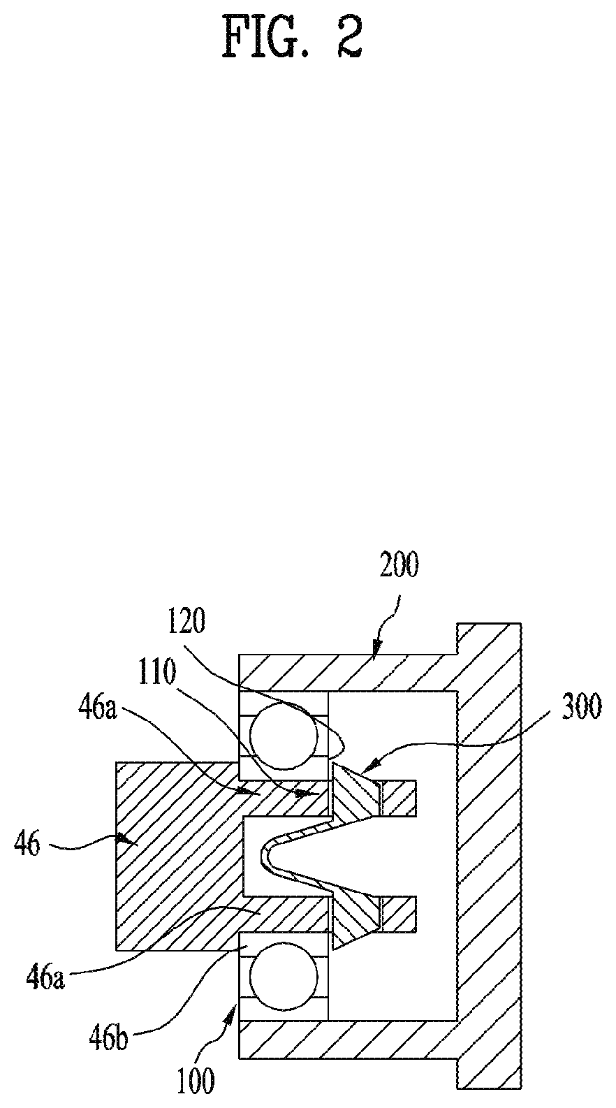
[0050] Referring to FIGS. 2 and 3, one embodiment for preventing the horizontal-direction movement of the shaft 46 to the left will be described.
[0051] A fixing latch 300 may be provided in one end of the shaft 46 and the horizontal movement of the shaft 46 to the left may be constrained by the fixing latch 300.
[0052] The fixing latch 300 will be described in detail as follows.
[0053] The fixing latch 300 may have a structure configured to be elastically folded or unfolded. As one example, the fixing latch 300 may include a latching portion 330 and a supporting portion 350 connected to the latching portion. The supporting portion 350 may elastically support the latching portion 330.
[0054] The shaft mounting portion 46a of the shaft 46 may have a hollow portion 462 to insert the fixing latch 300 therein; and an opening 464 that is in communication with the hollow portion 462. The latching portion 330 of the fixing latch 300 may be exposed to the outside of the shaft mounting portion 46a via the opening 463 of the shaft mounting portion 46a.
[0055] Each of the components will be described in detail.
[0056] First of all, the latching portion 330 of the fixing latch 300 will be described.
[0057] The shape of the latching portion 330 is not limited. The latching portion 330 may be formed in diverse shapes, only if some area of the latching portion is exposed outside via the opening 464.
[0058] As one example, the length Lh and the width Wh of the latching portion 330 may be equal to the length L and the width W of the opening 464 formed in the shaft mounting portion 46a. The latching portion 330 may be high enough to expose at least predetermined area to an outer surface of the shaft mounting portion 46a.
[0059] An upper area 334 of the latching portion 330 may be inclined downwardly from a front side towards a rear side. The tilted surface 334 may be linear or curved (the inclined surface is for convenient assembling and detailed description thereof will be made later). As one example, the height H1 of the front area 332 of the latching portion 330 may be larger than the height H of the opening 464 and the height H2 of the rear area 336 may be equal to the height H of the opening 464.
[0060] Next, the supporting portion 350 of the fixing latch 300 will be described.
[0061] The supporting portion 350 may elastically support the latching portion 330. In other words, the supporting portion 350 may be folded when it is inserted in the hollow 462 of the shaft mounting portion 46a and elastically unfolded after that. The shape of the supporting portion 350 may have a flexible structure (e.g., a plate spring structure) and the supporting portion 350 may be made of an elastic material.
[0062] The shapes of the supporting portion 350 are not limited and any shapes may be applicable, only if facilitating the above-noted function. As one example, the supporting portion 350 may include an extended area 352 that is forwardly extended from the latching portion 330. In addition, when a plurality of latching portions 330 are provided, the supporting portion 350 may include a connecting portion 354 for connecting each of the supporting portions 350 with each other (FIG. 2 illustrates two latching portions). In this instance, the supporting portion 350 may be configured as a kind of a plate spring that has elasticity.
[0063] Meanwhile, the fixing latch 300 may be made of diverse materials. Examples of the diverse materials may include an iron-based material, a non-iron-based material, a polymer material and the like.
[0064] Hereinafter, the hollow portion 462 and the opening 464 that are provided in the shaft shaft mounting portion 46a will be described.
[0065] The shapes of the hollow portion 462 formed in the shaft mounting portion 46a are not limited and any shapes are applicable, only if the hollow may accommodate the fixing latch 300, especially, the supporting portion 350. Also, the shapes of the opening 464 formed in the shaft mounting portion 46a may not be limited and the opening may have the length L or width W that are equal to shape of the latching portion 330, especially, the length Lh and the width Wh of the latching portion 330. The position of the opening 464 may not be limited but a front area of the opening 464 may be equal to the rear area of the sub-ball bearing 100.
[0066] Referring to FIG. 4, the assembling structure of the shaft 46, the sub-bearing 100 and the fixing latch 300 will be described.
[0067] As shown in FIG. 4(a), the fixing latch 300 may be pushed in the hollow portion 462 of the shaft mounting portion 46a. When the supporting portion 350 of the fixing latch having elasticity is narrowed, the fixing latch 300 may be pushed in the hollow portion 462.
[0068] As shown in FIG. 4(b), the latching portion 330 of the fixing latch inserted in the hollow portion 462 of the shaft mounting portion 46a may be located in the opening 464 of the shaft mounting portion 46a. Then, the latching portion 330 may be pushed in the opening 464 by the elasticity of the supporting portion 350 and projected outside via the opening. That is a state where the fixing latch 300 is assembled to the shaft mounting portion 46a. The shaft in that state may slide in the sub-ball bearing 100.
[0069] In this instance, the latching portion 330 may be downwardly inclined from the front side to the rear side as shown in FIG. 4(c). Hence, the latching portion 330 of the fixing latch may be naturally pressed and flexed radially inward enough to allow the shaft mounting portion 46a of the shaft 46 to penetrate the inner race of the sub-ball bearing 100.
[0070] As shown in FIG. 4(d), the shaft mounting portion 46a of the shaft may penetrate the inner race of the sub-ball bearing 100 and the latching portion 330 may be then unfolded or spread such that the latching portion 330 of the fixing latch may project towards the sub-ball bearing 100. In other words, the latching portion 330 of the fixing latch may face the rear area of the sub-ball bearing 100, in contact.
[0071] Once such the assembling is complete, the horizontal movement of the shaft 46 to the right may be constrained by the protrusion 46b of the shaft 46 and the horizontal movement of the shaft to the left may be constrained by the latching portion 330 of the fixing latch 330. According to the illustrated embodiment, the horizontal-direction movement of the shaft 46 to both the right and the left may be effectively constrained even if vibration occurs in the compressor.
[0072] Meanwhile, the above-noted embodiment illustrates and describes the two openings 464 of the shaft mounting portion 46a and the two corresponding latching portions 330. However, the present disclosure may not be limited to that embodiment. One or two or more openings and corresponding latching portions 330 may be provided. The plurality of the latching portions 330 may be arranged in bilateral or top-and-bottom symmetry. Even in case one latching portion 330 is provided, the supporting portion 350 may substantially have the same shape. As one example, the supporting portion 350 may be formed in a shape that is extended from the front area of the latching portion 330 to a predetermined length and towards the rear area to a predetermined length again. Also, the supporting portion 350 may be formed in a shape that is extended only to the front area of the latching portion 33. In this instance, the supporting portion 350 may be extended with a predetermined slope.
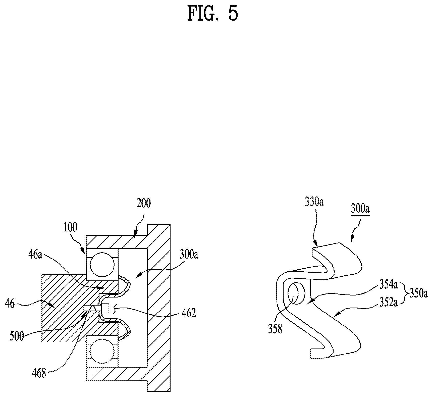
[0073] Referring to FIG. 5, another embodiment of the compressor according to the present disclosure will be described.
[0074] This embodiment has the same basic principle with the above-noted embodiment, except the structure configured to assemble the fixing latch to the shaft mounting portion.
[0075] To avoid complex explanation, different features of this embodiment from the above-noted embodiment will be described in detail.
[0076] The hollow portion 462 may be provided in the shaft mounting portion 46a and a coupling hole 468 may be provided in the hollow portion 462. Here, the opening for exposing the latching portion may not be formed in the shaft mounting portion 46a in this embodiment.
[0077] A fixing latch 300a may include a latching portion 330a and a supporting portion 350a. The supporting portion 350a may include the coupling hole 358. The shape of the latching portion 330a may not be limited but one side of the latching portion 330a may contact a rear area of the sub-ball bearing 100. The shape of the supporting portion 350a may not be limited but one side of the supporting portion 350a may be connected with the latching portion 330a and the other side may be extended towards the hollow portion 462 of the shaft mounting portion.
[0078] The process of coupling the fixing latch 300a to the shaft mounting portion 46a will be described.
[0079] The supporting portion 350a of the fixing latch 300a may be inserted in the hollow portion 462 of the shaft mounting portion 46a. Only the supporting portion 350a of the fixing latch 300a may be inserted in the hollow portion 462 in this embodiment, not the latching portion 300a. In this state, the fixing latch 300a may be coupled to the shaft mounting portion 46a. As one example, a screw 500 may be fastened to the coupling hole 468 of the shaft mounting portion 462 and the coupling hole 358 of the supporting portion 350a to couple them to each other. The process of assembling the shaft 46 having the fixing latch 300a to the sub-ball bearing is equal to the process of the above-noted embodiment.
[0080] In this embodiment, only the supporting portion 350a of the fixing latch 300a may be inserted in the hollow portion 462 and the latching portion 330a may not be inserted therein. Accordingly, it may be possible in this embodiment to lessen the length of the shaft mounting portion 46a, compared with the above-noted embodiment.
[0081] Referring to FIG. 6, a further embodiment of the compressor will be described.
[0082] This embodiment also has the basic principle that is substantially equal to the basic principles of the above embodiments, except a feature that the fixing latch is coupled to the shaft mounting portion.
[0083] To avoid complex explanation, different features of this embodiment from the above-noted embodiment will be described in detail.
[0084] In this embodiment, the shaft mounting portion 46a may include no hollow portion and no opening for exposing the latching portion. Here, the shaft mounting portion 46a may include the coupling hole 469.
[0085] The fixing latch 300b may include a latching portion 330b and a supporting potion 350b. The supporting portion 350b may include the coupling hole 468. The shape of the latching portion 330b may not be limited but one side of the supporting portion 350b may be connected with the latching portion 330b and the other side may be extended towards an outer surface of the shaft mounting portion 46a. In this embodiment, one end of the latching portion 330b and the supporting portion 350b may be position on the same plane.
[0086] The coupling process of the fixing latch 300b to the shaft mounting portion 46a will be described hereinafter.
[0087] The shaft mounting portion 46a according to this embodiment may include no hollow portion such that the supporting portion 350b of the fixing latch 300b may contact with one cross sectional surface of the shaft mounting portion 46a. In this state, the fixing latch 300b may be coupled to the shaft mounting portion 46a. As one example, a screw 500 may be fastened to the coupling hole 468 of the shaft mounting portion 462 and the coupling hole 458 of the supporting portion 350b to couple them to each other. The process of assembling the shaft 46 having the fixing latch 300b to the sub-ball bearing is equal to the process of the above-noted embodiment.
[0088] In this embodiment, it is unnecessary to manufacture a hollow portion in the shaft mounting portion 46a. In addition, the latching portion 330b and the supporting portion 350b that are provided in the fixing latch 300b may not be inserted in the shaft mounting portion 46a according to this embodiment. Accordingly, it may be possible in this embodiment to lessen the length of the shaft mounting portion 46a, compared with the above-noted embodiment.
[0089] The exemplary embodiment illustrated in FIG. 6 shows the fixing latch 300b including the plurality of the latching portions 330b that are radially arranged at preset intervals; and the supporting portion 350b that is approximately circular-shaped. However, the embodiment may not be limited thereto and one latching portion 330b or two or more latching portions 330b may be provided.
[0090] Meanwhile, the elements with no additional description in the embodiments may be substantially equal to the corresponding ones in the other embodiments. Even without special comments, the technical feature described in one embodiment may be equally applied to the other embodiments, unless opposed to each other.
[0091] As described above, the compressor according to the present disclosure may effectively prevent the shaft from being moved in the horizontal direction, even if vibration occurs. Accordingly, the damage to the other components caused by the collision with the horizontally moving shaft may be prevented and then the reliability of the compressor may be enhanced, even if vibration occurs in the compressor.
[0092] Furthermore, the horizontal-direction movement of the shaft may be prevented even when the shaft is inserted in the sub-ball bearing without a press fit. Accordingly, the manufacturing tolerances for the shaft that is inserted in the sub-ball bearing may be reduced and it may be possible to simplify the assembly process of the compressor.
[0093] As the present features may be embodied in several forms without departing from the characteristics thereof, it should also be understood that the above-described embodiments are not limited by any of the details of the foregoing description, unless otherwise specified, but rather should be considered broadly within its scope as defined in the appended claims, and therefore all changes and modifications that fall within the metes and bounds of the claims, or equivalents of such metes and bounds, are therefore intended to be embraced by the appended claims.
[0094] As one example, the embodiments disclose the main bearing and the ball bearing as the sub-bearing are described but the present disclosure may not be limited thereto. Other diverse types of bearings may be used.
[0095] It will be apparent to those skilled in the art that various modifications and variations can be made in the present disclosure without departing from the spirit or scope of the disclosures. Thus, it is intended that the present disclosure covers the modifications and variations of this disclosure provided they come within the scope of the appended claims and their equivalents.
* * * * *
D00000
D00001
D00002
D00003
D00004
D00005
D00006
XML
uspto.report is an independent third-party trademark research tool that is not affiliated, endorsed, or sponsored by the United States Patent and Trademark Office (USPTO) or any other governmental organization. The information provided by uspto.report is based on publicly available data at the time of writing and is intended for informational purposes only.
While we strive to provide accurate and up-to-date information, we do not guarantee the accuracy, completeness, reliability, or suitability of the information displayed on this site. The use of this site is at your own risk. Any reliance you place on such information is therefore strictly at your own risk.
All official trademark data, including owner information, should be verified by visiting the official USPTO website at www.uspto.gov. This site is not intended to replace professional legal advice and should not be used as a substitute for consulting with a legal professional who is knowledgeable about trademark law.