Jet Regulator
STEIN; Alexander ; et al.
U.S. patent application number 16/630980 was filed with the patent office on 2020-07-16 for jet regulator. This patent application is currently assigned to Neoperl GmbH. The applicant listed for this patent is Neoperl GmbH. Invention is credited to Gerhard BLUM, Alexander STEIN.
| Application Number | 20200224395 16/630980 |
| Document ID | / |
| Family ID | 62986071 |
| Filed Date | 2020-07-16 |
| United States Patent Application | 20200224395 |
| Kind Code | A1 |
| STEIN; Alexander ; et al. | July 16, 2020 |
JET REGULATOR
Abstract
A jet regulator (104) including a jet regulator housing (1) having an outer thread (2) on the outer circumference of the housing for screwing into an internal thread (3) in the water outlet (4) of a sanitary outlet fitting. The jet regulator housing (1) has a thread profile as an outer thread (2) on the housing outer circumference, deviating at least in sections from a thread groove that is continuously spiraling around a cylindrical wall, which outer thread cooperates in this region in a self-adapting manner with the internal thread (3) provided in the water outlet (4) and/or has at least one cross-sectional widening (6, 7) which is made of the same material as the housing section of the jet regulator housing (1) supporting the outer thread (2) and which is integrally formed thereon, and which can be sealingly placed on the water outlet (4) on the end side and/or on the inner circumference side.
| Inventors: | STEIN; Alexander; (Ihringen, DE) ; BLUM; Gerhard; (Gutach, DE) | ||||||||||
| Applicant: |
|
||||||||||
|---|---|---|---|---|---|---|---|---|---|---|---|
| Assignee: | Neoperl GmbH Mullheim DE |
||||||||||
| Family ID: | 62986071 | ||||||||||
| Appl. No.: | 16/630980 | ||||||||||
| Filed: | July 13, 2018 | ||||||||||
| PCT Filed: | July 13, 2018 | ||||||||||
| PCT NO: | PCT/EP2018/069074 | ||||||||||
| 371 Date: | January 14, 2020 |
| Current U.S. Class: | 1/1 |
| Current CPC Class: | E03C 1/084 20130101; E03C 2001/026 20130101; B05B 7/0425 20130101; E03C 1/086 20130101; E03C 1/08 20130101 |
| International Class: | E03C 1/086 20060101 E03C001/086; E03C 1/084 20060101 E03C001/084 |
Foreign Application Data
| Date | Code | Application Number |
|---|---|---|
| Sep 6, 2017 | DE | 202017105378.4 |
Claims
1. A jet regulator (101, 104, 111, 115) comprising: a jet regulator housing (1) having a housing outer circumference on which an outer thread (2) is located that is adapted for screwing into an inner thread (3) in a water outlet (4) of a sanitary outlet fitting, the outer thread includes a thread profile that deviates at least in regions from a thread groove extending continuously in a helical manner about a cylindrical wall, said outer thread (2) cooperates in said regions in a self-adapting manner with the inner thread (3) provided in the water outlet (4).
2. The jet regulator as claimed in claim 1, wherein a sub-region of the jet regulator housing (1), disposed on an outflow side of the outer thread (2), is angled in a direction that is adapted to be toward an inner circumference of the water outlet (4) such a way that a drainage annular space (8) is adapted to be formed between said housing sub-region and the inner circumference of the water outlet.
3. A jet regulator (127, 130) comprising: a jet regulator housing (1) having a housing outer circumference on which an outer thread (2) is located that is adapted for screwing into an inner thread (3) in a water outlet of a sanitary outlet fitting, and further including on the housing outer circumference, at least one cross-sectional widening (6, 7) which is materially identical with a housing portion of the jet regulator housing (1) that supports the outer thread (2) and which is formed integrally thereon, and which said cross-sectional widening is adapted to bear sealingly on at least one of an end face or an inner circumferential face of the water outlet (4), a housing sub-region of the jet regulator housing (1), disposed on an outflow side of the outer thread (2), is angled in a direction that is adapted to be toward an inner circumference of the water outlet (4) such that a drainage annular space (8) is adapted to be formed between said housing sub-region and the inner circumference of the water outlet.
4. The jet regulator as claimed in claim 3, wherein the jet regulator (101, 104, 111, 115, 127, 130) is configured as a jet aerator which mixes water flowing therethrough with ambient air and which for this purpose includes, in a housing portion of the jet regulator housing (1) disposed on the outflow side of the outer thread (2), at least one aeration opening (9) that is provided on the housing circumference or on an housing end face of the jet regulator housing (1).
5. The jet regulator as claimed in claim 3, wherein the jet regulator housing (1) has at least two housing parts (10, 11) that are connectable to each other.
6. The jet regulator as claimed in claim 5, wherein a first of the at least two housing parts (10) disposed on the outflow side supports the outer thread (2).
7. The jet regulator as claimed in claim 6, wherein an outflow-side first housing part (10) is connectable on an inflow side to a second one of the at least two housing parts (11) of the jet regulator housing (1), said second housing part (11) supports a jet splitter which is adapted to split the water flowing therethrough into a multiplicity of individual jets.
8. The jet regulator as claimed in claim 7, wherein the jet splitter comprises a diffuser which has a cup-shaped jet splitter insert (12) which, on a cup circumference of said cup shape, has a plurality of splitter openings (13), and said jet splitter insert (12) has a cup base (14) configured as an impact face that is adapted to deflect the inflowing water toward the splitter openings (13).
9. The jet regulator as claimed in claim 8, wherein the second housing part (11) engages around the jet splitter insert (12), and the second housing part (11) tapers, at least in a region of the cylinder openings (13), such a way that an annular gap (15) is formed between the jet splitter insert (12) and a housing inner circumference of the second housing part (11), said annular gap (15) tapers on an outflow side toward an annular opening (16) that opens into a housing interior.
10. The jet regulator as claimed in claim 3, further comprising a sleeve-shaped guide wall (17) is provided in the jet regulator housing (1), and least one aeration duct (18) between a housing inner circumference of the jet regulator housing (2) and the guide wall (17), said which aeration duct (18) leads to a housing interior from at least one aeration opening (9) disposed on the housing outflow side.
11. The jet regulator as claimed in claim 10, further comprising an outflow-side housing end edge of the jet regulator housing (1) being configured as a lip seal (21) which is adapted to bear on the inner circumference of the water outlet (4) or lies close to the inner circumference of the water outlet (4).
12. The jet regulator as claimed in claim 10 or 11, further comprising at least one drainage opening (22) is provided in a sub-region of the housing wall of the jet regulator housing (1) disposed between the outflow-side housing end face and the outer thread (2), said drainage opening (22) leads from the drainage annular space (8) to the aeration duct (18).
13. The jet regulator as claimed in claim 13, further comprising a mesh or net structure (23) comprising webs that intersect one another at intersection nodes formed integrally on the guide wall (17) on the outflow side.
14. The jet regulator as claimed in claim 13, wherein the guide wall (17) is connected in a rotationally fixed to the jet regulator housing (1), and at least one tool engagement face for a driving tool is provided on at least one of the guide wall (17) or on the mesh or net structure (23).
15. The jet regulator as claimed in claim 14, further comprising at least one slit-shaped recess (29) adapted for insertion of a coin used as the driving tool, or of another driving tool, is provided in the mesh or net structure, said recess (29) is delimited by opposite slit longitudinal walls that form tool engagement faces for the driving tool.
16. The jet regulator as claimed in claim 3, wherein an outer envelope body, formed by the outer thread (2) on the jet regulator housing (1) adapted to be screwed into the cylindrical inner thread, widens toward the outflow side.
17. The jet regulator as claimed in claim 3, further comprising at least one molding (26, 28) which serves as a liquids bulkhead and which projects into at least one thread groove of the outer thread (2) on the housing outer circumference of the jet regulator housing (1).
18. The jet regulator as claimed in claim 17, wherein the at least one molding (26, 28) reaches as far as the envelope body enveloping the outer thread (2) or at least in regions projects beyond this envelope body.
19. The jet regulator as claimed in claim 18, wherein the at least one molding is configured as a separation wall (26) that extends across at least two neighboring thread grooves of the outer thread.
20. The jet regulator as claimed in claim 19, wherein the at least one separation wall (26) runs approximately axially parallel to a housing longitudinal axis of the jet regulator housing (1).
21. The jet regulator as claimed in claim 19, wherein the at least one molding (28) is cam-shaped, and the cam-shaped molding (28) in the thread groove extends approximately in a groove longitudinal direction.
22. The jet regulator as claimed in claim 3, wherein the thread profile of the outer thread (2), projecting beyond the thread groove, widens at least in regions to form at least one cross-sectional widening (6; 7).
23. The jet regulator as claimed in claim 22, wherein the at least one cross-sectional widening (6; 7) projects like a flange on the housing outer circumference of the jet regulator housing (1).
24. The jet regulator as claimed in claim 23, wherein the at least one flange-shaped cross-sectional widening (6; 7) extends, in a housing circumferential direction of the jet regulator housing, across at least one drainage opening provided in a sub-region of the housing wall of the jet regulator housing (1) disposed between the outflow-side housing end face and the outer thread (2).
25. The jet regulator as claimed in claim 24, wherein the at least one flange-like cross-sectional widening (6; 7) on the housing outer circumference of the jet regulator housing is provided between the outer thread and the at least one drainage opening (22).
26. The jet regulator as claimed in claim 25, wherein the flange-like cross-sectional widening (7) is configured as an annular flange that encircles the jet regulator housing (1).
27. The jet regulator as claimed in claim 26, wherein the at least one flange-like cross-sectional widening (6; 7) is configured as a screw-in abutment which is adapted to limit a screwing of the outer thread (2) into the inner thread (3) in the water outlet (4) of the outlet fitting.
28. The jet regulator as claimed in claim 3, wherein the jet regulator (101, 104, 111, 115, 127, 130) is designed free of a sealing ring and is adapted to be installed makes do without a sealing ring of elastic material produced separately from the jet regulator housing (1).
29. The jet regulator as claimed in claim 9, wherein the jet splitter comprises a perforated plate (30) which has splitter openings (31).
30. The jet regulator as claimed in claim 29, wherein the splitter openings (31) taper, at least in regions, in the throughflow direction.
31. The jet regulator as claimed in claim 30, further comprising that at least one insert part (32, 33) arranged at a distance downstream from the jet splitter in the flow direction, said insert part (32, 33) has a mesh or net structure comprised of webs that intersect one another at intersection nodes.
32. The jet regulator as claimed in claim 31, wherein the mesh or net structure (23) provided in the at least one insert part (32, 33) has throughflow openings (24) which have at least one of a honeycomb-shaped or hexagonal clear opening cross section.
33. The jet regulator as claimed in claim 31, wherein the mesh or net structure provided in the at least one insert part (32, 33) is formed from at least two concentrically encircling webs which are connected to a group of radial webs.
34. The jet regulator as claimed in claim 31, wherein the mesh or net structure provided in the at least one insert part has a group of axially parallel first webs which intersect a group of axially parallel second webs which are disposed at an angle in relation to said group of axially parallel first webs.
35. The jet regulator as claimed in claim 31, wherein the mesh or net structure provided in the insert part is formed by mutually intersecting webs which are disposed at an angle to each other such that said mesh or net structure is formed from throughflow openings that are non-uniformly shaped in terms of clear open cross sections thereof.
Description
TECHNICAL FIELD
[0001] The invention relates to a jet regulator having a jet regulator housing which, on its housing outer circumference, has an outer thread for screwing into an inner thread in the water outlet of a sanitary outlet fitting.
BACKGROUND
[0002] Jet regulators in a wide variety of embodiments have already been provided for shaping the water flowing out of the water outlet of a sanitary outlet fitting so as to form a homogeneous and non-sputtering water jet. To this end, the previously known jet regulators are mounted in the region of the water outlet on a sanitary outlet fitting.
[0003] A jet regulator is already known from EP 3 153 633 A1, which jet regulator, on the housing outer circumference of its jet regulator housing, has an outer thread with which the jet regulator housing can be screwed into an inner thread in the water outlet of a sanitary outlet fitting. In order for the previously known jet regulator not to have to be sealed by at least one separate sealing ring made of elastic material in the region of the annular gap located between the jet regulator housing and the inner circumference of the water outlet, the outer thread in the case of the previously known jet regulator is provided directly below at least one aeration opening which penetrates the housing circumferential wall of the jet regulator housing, and by way of which aeration opening, besides the ambient air, the leakage water which was able to pass the annular gap via the screw connection between outer thread and inner thread can also be sucked into the housing interior. As soon as water flows through the previously known jet regulator and to this extent a negative pressure thereby arises at the at least one aeration opening of said jet regulator, the previously known jet regulator is capable of entraining a partial quantity of the leakage water passing the screw connection into the housing interior. However, since the aeration openings potentially extend only across part of the circumference of the jet regulator housing, there is the risk that the balance of the leakage water passes the annular gap remaining between the housing outer circumference of the jet regulator housing and the inner circumference in the water outlet of the sanitary outlet fitting and emerges disruptively at the outflow-side end face of the water outlet.
SUMMARY
[0004] Therefore, there is in particular the object of making available a jet regulator of the type mentioned at the outset which is distinguished by significantly improved sealing in the region between the housing outer circumference of the jet regulator housing and the inner circumference in the water outlet of the sanitary outlet fitting.
[0005] In the case of the jet regulator of the type mentioned at the outset, this object is achieved according to the invention by the fact that jet regulator housing has, on its housing outer circumference, a thread profile as outer thread that deviates at least in regions from a thread groove extending continuously in a helical manner about a cylindrical wall, which outer thread cooperates in this region in a self-adapting manner with the inner thread provided in the water outlet.
[0006] The jet regulator according to the invention has a jet regulator housing which has an outer thread on its housing outer circumference. With the outer thread provided on the housing outer circumference, the jet regulator according to the invention can be screwed into an inner thread in the water outlet of a sanitary outlet fitting so as to shape the water emerging there into a homogenous, non-sputtering and optionally also sparkling soft water jet. To ensure that the annular zone remaining between the housing outer circumference of the jet regulator housing and the inner circumference of the water outlet is sealed off in respect of uncontrolled emergence of leakage water, provision is made as per the aforementioned proposal according to the invention that the jet regulator housing has as the outer thread a thread profile which, at least in regions, deviates from a thread groove that extends continuously in a helical manner about a cylindrical wall. In this thread profile that at least in regions is designed in a deviating manner, the outer thread interacts in a self-adapting manner with the inner thread provided in the water outlet, in such a way that the screw connection provides particularly good sealing in this region.
[0007] In a refinement according to the aforementioned invention, provision is made that a housing end edge region of the jet regulator housing disposed on the outflow side of the outer thread is angled in the direction toward the inner circumference of the water outlet in such a way that a drainage annular space is formed between this housing end edge region and the inner circumference of the water outlet. Leakage water which, by way of the screw connection, passes through the annular zone between the housing outer circumference and the inner circumference of the water outlet as far as the outflow-side circumference end region of the jet regulator housing is collected there in a drainage annular space which is formed between the outflow-side housing end edge region and the inner circumference of the water outlet.
[0008] The invention also concerns a jet regulator of the aforementioned type whose jet regulator housing has, on its housing outer circumference, at least one cross-sectional widening which is materially identical with the housing portion of the jet regulator housing that supports the outer thread and which is formed integrally thereon, and which cross-sectional widening can bear sealingly on the end face and/or the inner circumferential face of the water outlet.
[0009] Such a jet regulator is already known from DE 10 2010 023 664 A1. The latter document in fact already describes a sanitary outlet fitting with a water outlet having an outlet opening defined by an inner circumferential wall of the outlet fitting, on which inner circumferential wall an inner thread is provided into which a sleeve-shaped outlet mouthpiece with an outer thread can be screwed. A jet regulator configured as an insert cartridge is insertable into the sleeve-shaped outlet mouthpiece. The outlet mouthpiece receiving the jet regulator has, below its outer thread in the screwing-in direction, an annular groove for receiving a sealing ring, which annular groove is adjoined by a cross-sectional widening projecting like a flange on the outer circumference. The outlet mouthpiece can thus be screwed into the inner thread in the water outlet of the outlet fitting until the flange-like cross-sectional widening defining the annular groove and serving as insertion abutment abuts the inner circumferential wall in the water outlet of the outlet fitting. Although this cross-sectional widening serving as insertion abutment on the outlet mouthpiece is able to seal an annular gap remaining between the outer circumference of the outlet mouthpiece on the one hand and the water outlet on the other hand, it is unable to eliminate a loss of leaktightness between the jet regulator housing and the inner circumference of the outlet mouthpiece.
[0010] In the case of this jet regulator too, there is therefore the object already mentioned above of achieving considerably improved sealing in the region between the housing outer circumference of the jet regulator housing and the inner circumference in the water outlet of the sanitary outlet fitting.
[0011] In this previously known jet regulator, this object is achieved according to the invention in particular by the fact that a housing sub-region of the jet regulator disposed on the outflow side of the outer thread is angled in the direction toward the inner circumference of the water outlet in such a way that a drainage annular space is formed between this housing sub-region and the inner circumference of the water outlet.
[0012] The jet regulator configured as per this proposal according to the invention has a jet regulator housing having at least one cross-sectional widening which is materially identical with the housing portion of the jet regulator housing that supports the outer thread and which is formed integrally thereon, and which cross-sectional widening can bear sealingly on the end face and/or the inner circumferential face of the water outlet. According to the invention, provision is now made that a housing end edge region of the jet regulator housing disposed on the outflow side of the outer thread is angled in the direction toward the inner circumference of the water outlet in such a way that a drainage annular space is formed between this housing end edge region and the inner circumference of the water outlet. Leakage water which, by way of the screw connection, passes through the annular zone between the housing outer circumference and the inner circumference of the water outlet as far as the outflow-side circumference end region of the jet regulator housing is collected there in a drainage annular space which is formed between the outflow-side housing end edge region and the inner circumference of the water outlet. By virtue of these particular design features of the jet regulator housing, uncontrolled emergence of leakage water through the annular zone provided between the outer circumference of the jet regulator housing and the inner circumference of the water outlet is effectively avoided under almost all operating conditions, even when the jet regulator according to the invention is designed without additional elastic sealing rings for axially or radially sealing the jet regulator housing. With the jet regulator according to the invention, the abovementioned annular zone is reliably leaktight even when the inner thread in the water outlet cannot be produced with high precision, and when the annular shoulder in the water outlet required for the axial sealing is to be dispensed with in favor of lower manufacturing complexity in the production of the outlet fitting.
[0013] By virtue of its particular design features, the jet regulator according to the invention is comparatively non-sensitive to furring, even in the region of its jet regulator housing. Therefore, in a preferred embodiment according to the invention, provision is made that the jet regulator is configured as a jet aerator which mixes the water flowing therethrough with ambient air and which for this purpose, in a housing portion of the jet regulator housing disposed on the outflow side of the outer thread, has at least one aeration opening that is provided on the housing circumference or on the housing end face of the jet regulator housing.
[0014] Jet-forming structures are required in the housing interior in order for the jet regulator to be able to positively shape the water flowing through its jet regulator housing. In order for such jet-forming structures to be able to be inserted into the jet regulator housing in a simple manner, it is advantageous if the jet regulator housing has at least two housing parts that are connectable to each other, and if a first housing part disposed on the outflow side supports the outer thread. At least two neighboring housing parts of the jet regulator housing can then be connectable to each other non-releasably, but preferably releasably.
[0015] The water flowing through the jet regulator housing can be shaped particularly effectively if the outflow-side first housing part is connectable on the inflow side to a second housing part of the jet regulator housing, preferably releasably connectable, which second housing part supports a jet splitter which splits the water flowing therethrough into a multiplicity of individual jets.
[0016] In a preferred embodiment according to the invention, provision is made that the jet splitter is designed as a diffuser which has a cup-shaped jet splitter insert which, on the cup circumference of its cup shape, has a plurality of splitter openings, and which has a cup base configured as an impact face that deflects the inflowing water toward the splitter openings.
[0017] In order for the water flowing into the jet regulator housing to first be divided into individual jets and in order then for the individual jets to be accelerated in such a way that a negative pressure arises at the outflow side of the diffuser, it is advantageous if the second housing part engages around the jet splitter insert, and if the second housing part conically tapers, at least in the region of the cylinder openings, in such a way that an annular gap is formed between the jet splitter insert and the housing inner circumference of the second housing part, which annular gap tapers on the outflow side toward an annular opening that opens into the housing interior.
[0018] In a preferred refinement according to the invention, provision is made that a sleeve-shaped guide wall is provided in the jet regulator housing, and that at least one aeration duct is provided between the housing inner circumference of the jet regulator housing and the guide wall, which aeration duct leads to the housing interior from at least one aeration opening disposed on the housing outflow side. In this refining design embodiment, the jet regulator according to the invention has an outer surface, formed by the housing outer circumference, and an inner surface, formed by the guide wall. Since the at least one aeration duct and the at least one aeration opening can thus be disposed on the inner surface of the jet regulator configured as a jet aerator, rapid furring in the annular zone between the housing outer circumference of the jet regulator housing and the inner circumference in the water outlet is effectively counteracted.
[0019] In a particularly advantageous, since particularly leaktight, embodiment of the invention, provision is made that the outflow-side housing end edge of the jet regulator housing is configured as a lip seal which bears on the inner circumference of the water outlet or lies close to the inner circumference of the water outlet. The outflow-side housing end edge, configured as a lip seal, can bear tightly on the inner circumference of the water outlet. However, it is also possible for this housing end edge to only lie close to the inner circumference of the water outlet in such a way that the leakage water collected in the drainage annular space is retained there by virtue of the capillary forces, or an annular gap remaining between the lip seal, on the one hand, and the inner circumference of the water outlet, on the other hand, is tightly closed on account of furring with limescale which is functionally inconsequential and thus potentially desirable in this region.
[0020] In order for the drainage annular space to be continuously emptied during the operation of the jet regulator according to the invention, it is advantageous if at least one drainage opening is provided in the sub-region of the housing wall of the jet regulator housing disposed between the outflow-side housing end edge and the outer thread, which drainage opening leads from the drainage annular space to the aeration duct or to at least one of the aeration ducts. The ambient air that is sucked through the aeration duct into the housing interior of the jet aerator can thus entrain leakage water from the drainage openings, which leakage water in the housing interior mixes with the stream of water flowing through the jet regulator housing.
[0021] The functionally correct operation of the jet regulator according to the invention is also safeguarded against unauthorized manipulation if a mesh or a net structure comprised of webs that intersect one another at intersection nodes is formed integrally on the guide wall on the outflow side. This outflow-side mesh or net structure, which can also serve as a flow straightener that combines the water that is in particular mixed with ambient air so as to form a homogenous outflowing water jet, and the structures lying behind said mesh or net structure in the housing interior, can thus not be forced upward counter to the flow direction of the water.
[0022] In order to be able to screw the jet regulator according to the invention in a simple manner into the water outlet of a sanitary outlet fitting, it is advantageous if the guide wall is connected in a rotationally fixed and in particular integral manner to the jet regulator housing and in particular to the first housing part on the outflow side, and if at least one tool engagement face for a driving tool is provided on the guide wall and/or on the mesh or net structure.
[0023] In an embodiment according to the invention that is particularly simple to produce and convenient to handle, provision is made that at least one slit-shaped recess for the insertion of a coin used as the driving tool, or of another driving tool, is provided in the mesh or net structure, which recess is delimited by opposite slit longitudinal walls that form tool engagement faces for the driving tool.
[0024] In an embodiment according to the invention which is of simple construction and provides good sealing, and in which the outer thread forms a thread profile that deviates at least in regions from a thread groove extending continuously in a helical manner about a cylindrical wall, provision is made that the outer envelope circle of the outer thread on the jet regulator housing, intended to be screwed into the inner thread formed in the cylindrical water outlet, widens preferably conically toward the outflow side. In this embodiment, the outer thread, with its conically widened thread portion, digs its way deep into the encircling thread groove of the inner thread provided in the water outlet, in such a way that this annular zone between the outer thread on the housing outer circumference, on the one hand, and the inner thread in the water outlet, on the other hand, is effectively sealed off with respect to seeping of leakage water.
[0025] Any seeping of leakage water, if any, is to be expected via the screw connection between the inner thread and the outer thread. In order to secure the thread turns of this screw connection against seeping of leakage water, it is expedient if at least one molding which serves as a liquids bulkhead and which projects into at least one thread groove of the outer thread is provided on the housing outer circumference of the jet regulator housing.
[0026] In order that the molding serving as a liquids bulkhead is able to dig deep into the thread groove of the inner thread provided on the water outlet, it is expedient if the at least one molding reaches as far as the envelope circle enveloping the outer thread or at least in regions projects beyond this envelope circle.
[0027] Particularly effective sealing is facilitated if the at least one molding is configured as a separation wall extending across at least two neighboring thread grooves of the outer thread.
[0028] In an embodiment according to the invention which is convenient to handle, easy to produce and provides effective sealing, and in which the separation wall represents a deviation from a thread groove that extends continuously in a helical manner about a cylindrical wall, provision is made that the at least one separation wall runs at least axially parallel to the housing longitudinal axis of the jet regulator housing.
[0029] Additionally or alternatively, however, the deviation provided according to the invention in the outer thread can also be designed as at least one cam-shaped molding, wherein the cam-shaped molding in the thread groove extends approximately in the groove longitudinal direction.
[0030] However, it is also possible that the thread profile of the outer thread, projecting beyond the thread groove, widens at least in regions and preferably in an outflow-side thread portion, such that the outer thread, with this widening thread portion on the outflow side, can cut in a sealing manner deep into the inner thread.
[0031] In order to provide a cross-sectional widening on the housing outer circumference of the jet regulator housing, provision is made, in an illustrative embodiment according to the invention, that the at least one cross-sectional widening projects like a flange on the housing outer circumference of the jet regulator housing.
[0032] The at least one flange-like cross-sectional widening can extend, in the housing circumferential direction of the jet regulator housing, across at least one drainage opening.
[0033] To ensure that only a small amount of leakage water, if any, can seep into the drainage annular space, it is expedient if the at least one flange-like cross-sectional widening on the housing outer circumference of the jet regulator housing is provided between the outer thread and the at least one drainage opening.
[0034] In a particularly leaktight embodiment according to the invention, provision is made that the flange-like cross-sectional widening is configured as an annular flange that encircles the jet regulator housing.
[0035] In a preferred embodiment according to the invention, provision is made that the at least one flange-like cross-sectional widening is configured as a screw-in abutment which limits the screwing of the outer thread into the inner thread in the water outlet of the outlet fitting.
[0036] Since the annular zone located between the housing outer circumference of the jet regulator housing and the inner circumference of the water outlet is positively sealed in the case of the jet regulator according to the invention, provision is made, in a preferred embodiment according to the invention, that the jet regulator is designed free of a sealing ring and makes do without a sealing ring of elastic material produced separately from the jet regulator housing.
[0037] In the illustrative embodiment already described above, the jet splitter is designed as a diffuser. In certain uses, a differently configured illustrative embodiment is proposed in which the jet splitter is designed as a perforated plate which has splitter openings. To ensure that a corresponding negative pressure arises on the outflow side of the jet splitter designed as a perforated plate, it is advantageous if the splitter openings taper, at least in regions, in the throughflow direction.
[0038] To ensure that the individual jets coming from the jet splitter and optionally mixed with ambient air are then shaped again into one homogenous jet that emerges from the jet splitter without sputtering, it is advantageous if at least one insert part is arranged at a distance downstream from the jet splitter in the flow direction, which insert part has a mesh or net structure composed of webs that intersect one another at intersection nodes.
[0039] In advantageous developments according to the invention, provision is made that the mesh or net structure(s) provided in the at least one insert part and/or formed integrally on the guide wall has/have throughflow openings which have a honeycomb-shaped and/or hexagonal clear opening cross section.
[0040] In a differently configured illustrative embodiment, provision is made that the mesh or net structure(s) provided in the at least one insert part and/or formed integrally on the guide wall is/are formed from at least two concentrically encircling webs which are connected to a group of radial webs.
[0041] If, in at least one of the insert parts and/or on the guide wall in the jet regulator housing, a mesh or net structure is intended to be formed which has diamond-shaped or rectangular throughflow openings, it is advantageous if the mesh or net structure(s) provided in the at least one insert part and/or formed integrally on the guide wall has/have a group of axially parallel first webs which intersect a group of axially parallel second webs which are disposed at an angle and preferably at a right angle in relation to said group of axially parallel first webs.
[0042] In a further proposal according to the invention, provision is made that the mesh or net structure(s) provided in the insert part and/or formed integrally on the guide wall is/are formed by mutually intersecting webs which are disposed at an angle to each other in such a way that said mesh or net structure(s) is/are formed ornamentally from throughflow openings that are non-uniformly shaped in terms of their clear open cross section.
BRIEF DESCRIPTION OF THE DRAWINGS
[0043] Refinements according to the invention will become clear from the claims in conjunction with the drawing and the description. The invention is described in more detail below on the basis of preferred illustrative embodiments.
[0044] In the drawings:
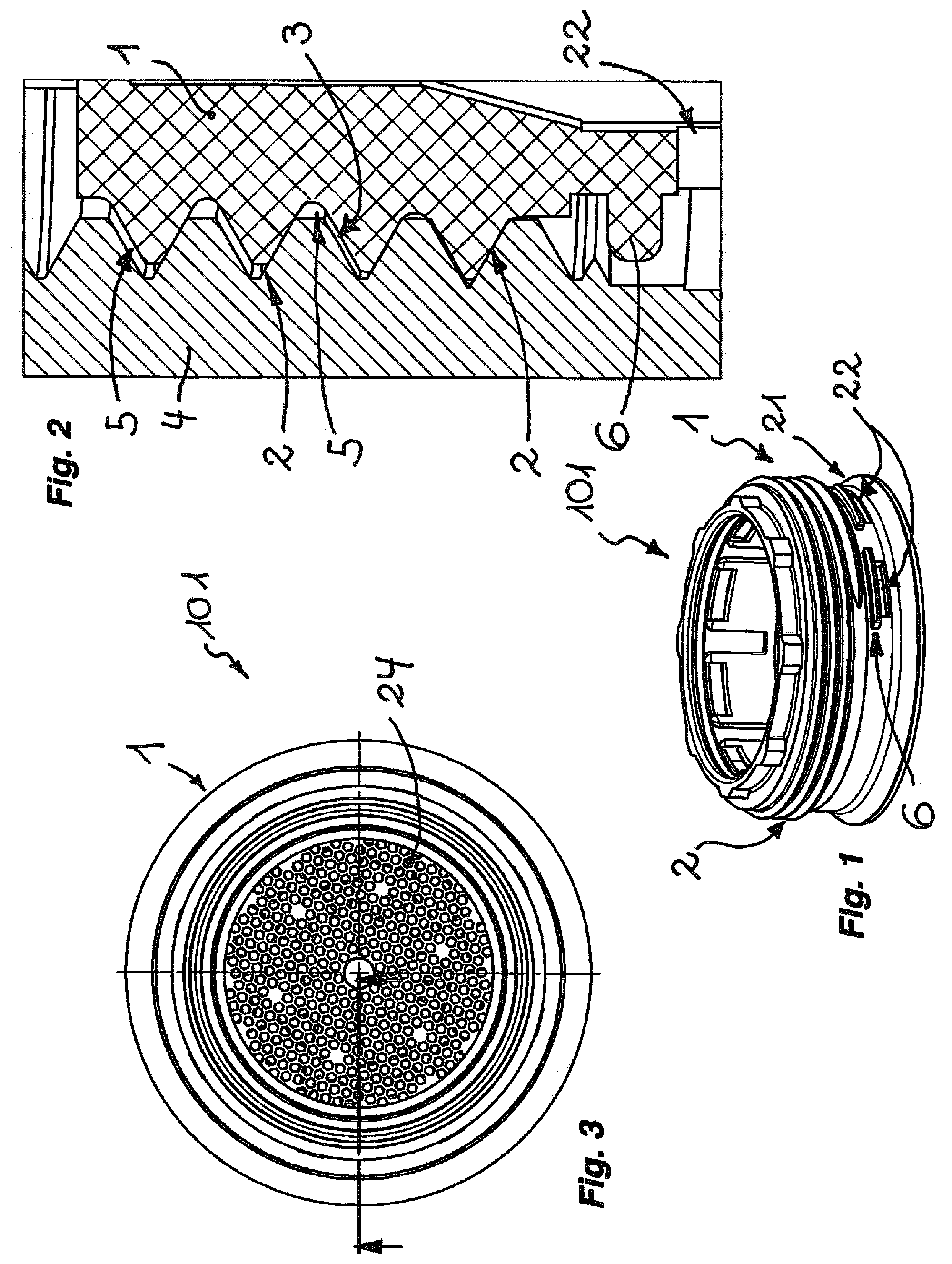
[0045] FIG. 1 shows a perspective view of the jet regulator housing of a jet regulator which, on its jet regulator housing, has an outer thread with which the jet regulator can be screwed into an inner thread on the water outlet of a sanitary outlet fitting, wherein the housing end edge region disposed on the outflow side of the outer thread is angled outward in such a way that a drainage annular space forms between this housing end edge region and the inner circumference of the water outlet (not shown in any detail here),
[0046] FIG. 2 shows the jet regulator housing from FIG. 1 screwed into an inner thread in the water outlet, in a longitudinal section detail in the region of the outer thread,
[0047] FIG. 3 shows the jet regulator housing from FIGS. 1 and 2 in a plan view of its outflow-side housing end face,
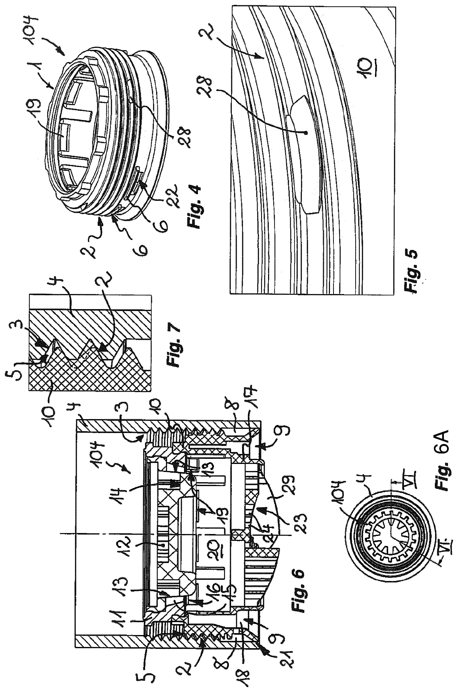
[0048] FIG. 4 shows the jet regulator housing of a further jet regulator in a perspective view, wherein an outer thread is provided on the housing outer circumference of the jet regulator housing, which outer thread has, in a thread groove, at least one molding that projects in the shape of a cam,
[0049] FIG. 5 shows the outer thread of the jet regulator housing shown in FIG. 4, in a perspective view of a detail in the region of the cam-shaped molding,
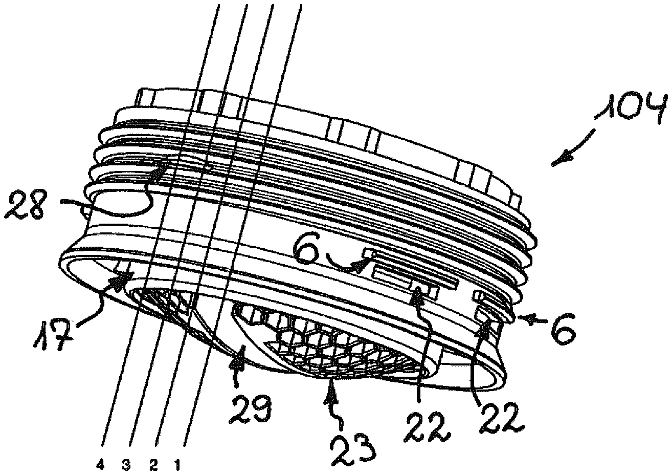
[0050] FIG. 6 shows the jet regulator equipped with the jet regulator housing from FIGS. 4 and 5, which jet regulator is screwed with its outer thread into an inner thread in the water outlet of a sanitary outlet fitting, wherein the jet regulator is shown in a longitudinal section through the section plane VI.-VI. in FIG. 6A, and wherein
[0051] FIG. 6A shows the jet regulator in a plan view of its inflow side,
[0052] FIG. 7 shows the screw connection provided between the jet regulator from FIG. 6 and the water outlet, in a longitudinal section detail in the region of the cam-shaped molding,
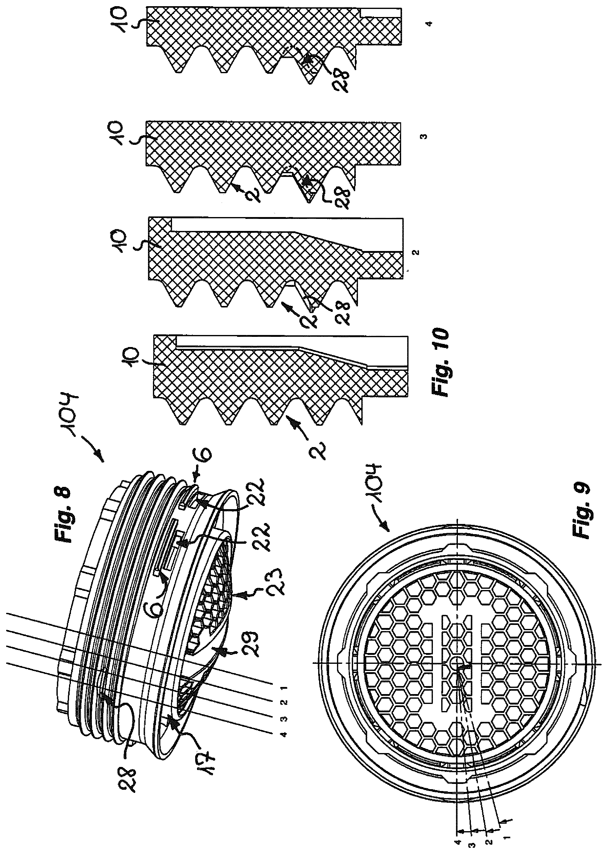
[0053] FIG. 8 shows the jet regulator from FIG. 6 with the jet regulator housing already shown in FIGS. 4 to 7,
[0054] FIG. 9 shows the jet regulator from FIGS. 6 and 8 in a plan view of the outflow-side housing end face,
[0055] FIG. 10 shows the outer thread on the jet regulator housing of the jet regulator shown in FIGS. 6, 8 and 9, said outer thread being sectioned longitudinally in four angular positions, wherein the angular positions used for the longitudinal section are shown and sequentially numbered in FIGS. 8 and 9,
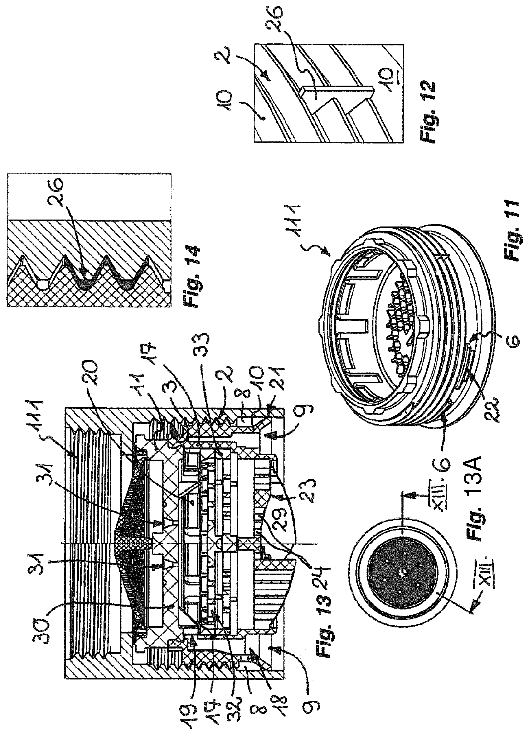
[0056] FIG. 11 shows the jet regulator housing of a further jet regulator, wherein at least one separation wall can be seen that projects beyond the outer thread provided on the housing outer circumference and that is configured as a liquids bulkhead,
[0057] FIG. 12 shows the outer thread provided on the housing outer circumference of the jet regulator housing shown in FIG. 11, in a perspective view of a detail in the region of the separation wall serving as a liquids bulkhead,
[0058] FIG. 13 shows the jet regulator designed using the jet regulator housing shown in FIG. 11, which jet regulator is also here screwed into the water outlet of a sanitary outlet fitting, in a longitudinal section through section plane XIII.-XIII. according to FIG. 13A, wherein
[0059] FIG. 13A shows the jet regulator in a plan view of the inflow side,
[0060] FIG. 14 shows the outer thread of the jet regulator shown in FIG. 13 in a longitudinal section of a detail in the region of the separation wall shown in FIGS. 11 and 12, said outer thread interacting with the inner thread in the water outlet,
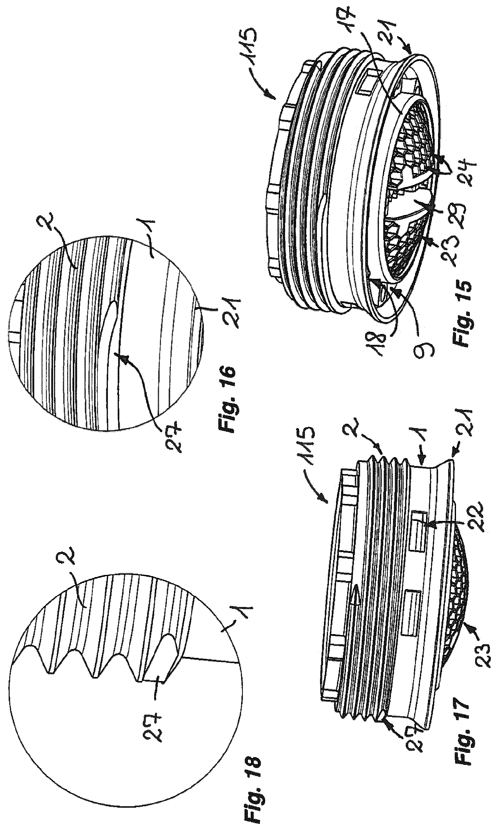
[0061] FIG. 15 shows a further jet regulator, of which the outer thread provided on the housing outer circumference in an outflow-side sub-region has in some regions a thread profile that deviates from a thread groove extending continuously in a helical manner about a cylindrical wall, wherein this deviation in the thread profile can be cut sealingly into the inner thread in the water outlet,
[0062] FIG. 16 shows the outer thread of the jet regulator shown in FIG. 15, in a perspective view of a detail in the region of the deviation in the outer thread,
[0063] FIG. 17 shows the jet regulator from FIGS. 15 and 16 in a perspective side view,
[0064] FIG. 18 shows the jet regulator already shown in FIGS. 15 to 17, in a perspective view of a detail in the region of the thread profile of the outer thread that is designed deviating on the outflow side,
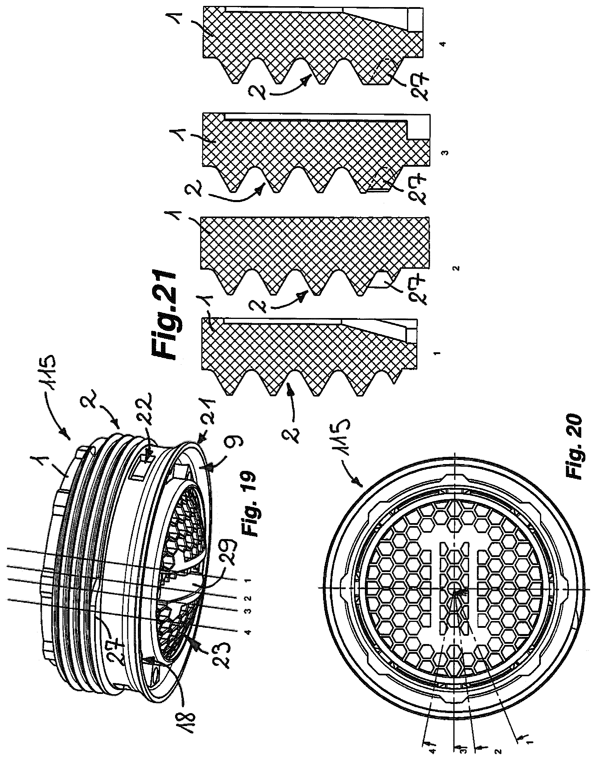
[0065] FIG. 19 shows the jet regulator from FIGS. 15 to 18 in a perspective view from below,
[0066] FIG. 20 shows the jet regulator from FIGS. 15 to 19 in a plan view of the outflow-side housing end face of the jet regulator housing,
[0067] FIG. 21 shows the outer thread longitudinally sectioned in four different angular positions, wherein the angular positions shown are sequentially numbered and illustrated in more detail in FIGS. 19 and 20,
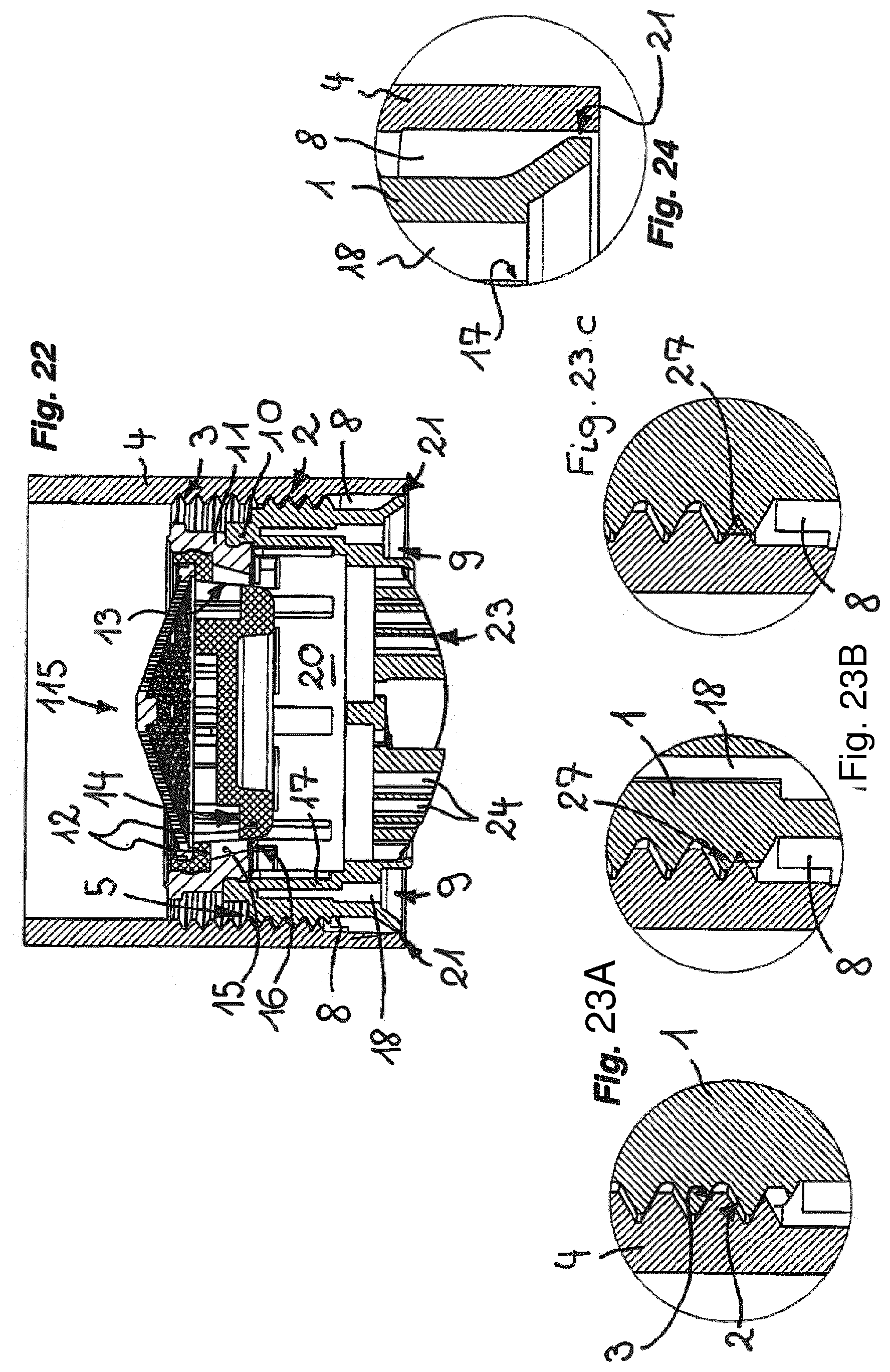
[0068] FIG. 22 shows the jet regulator shown in FIGS. 15 to 21, in a longitudinal section in the water outlet of a sanitary outlet fitting,
[0069] FIG. 23A to FIG. 23C show the jet regulator from FIG. 15 to FIG. 22 in views of details in the region of the screw connection thereof, wherein FIG. 23A shows the jet regulator, not yet completely screwed into the water outlet, in the region of its outer thread interacting with the inner thread in the water outlet, and FIG. 23B shows the screw connection interacting between the outer thread and the inner thread in the water outlet, wherein the thread deviation provided on the outflow-side end region of the outer thread begins to cut into the inner thread, and wherein the screw connection between the outer thread on the jet regulator housing and the inner thread in the water outlet is illustrated in the screwed-in end position in FIG. 23C,
[0070] FIG. 24 shows the jet regulator housing of the jet regulator shown in FIGS. 15 to 22, in a longitudinal section of a detail in the region of the drainage annular space,
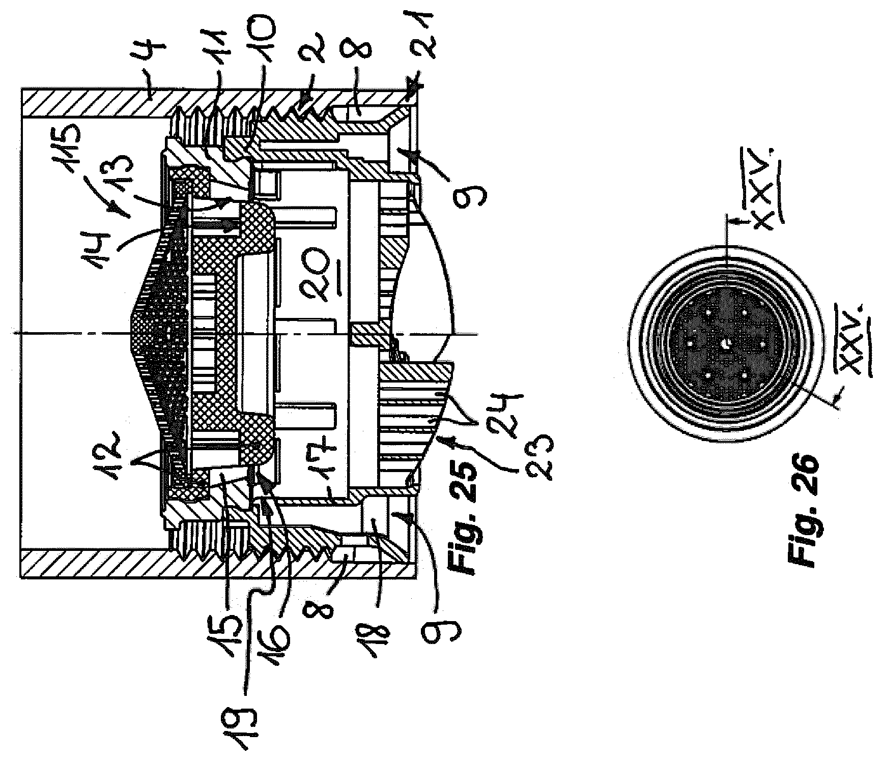
[0071] FIG. 25 shows the jet regulator from FIGS. 15 to 22 screwed into the water outlet of a sanitary outlet fitting, in a longitudinal section through section plane XXV.-XXV. according to FIG. 26,
[0072] FIG. 26 shows the jet regulator from FIGS. 15 to 22 and 25 in a plan view of the inflow side of this jet regulator and of the dome screen provided there at the inflow side,
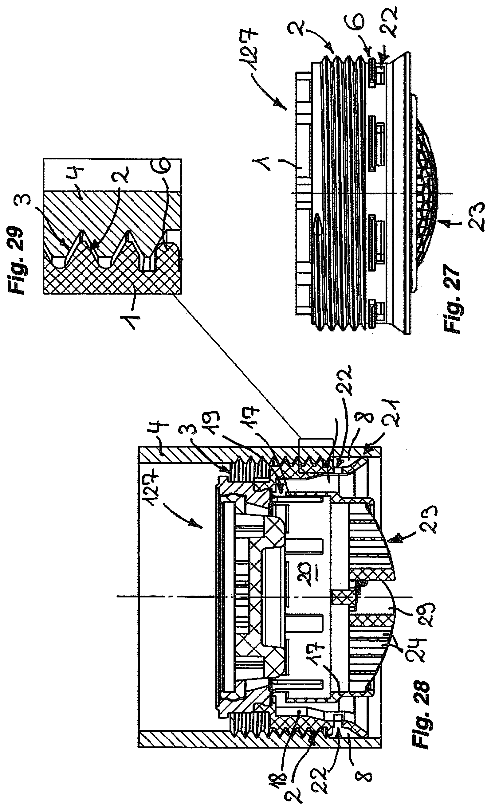
[0073] FIG. 27 shows a side view of a further jet regulator in which the drainage annular space is connected by way of drainage openings to an aeration duct that runs in an annular manner in the housing interior, wherein flange-like cross-sectional widenings, which limit seeping of leakage water into the drainage annular space, project above the drainage openings,
[0074] FIG. 28 shows a longitudinal section through the jet regulator produced using the jet regulator housing shown in FIG. 27,
[0075] FIG. 29 shows the jet regulator from FIG. 28 in a longitudinal section through a detail of the screw connection between the jet regulator housing, on the one hand, and the inner thread provided in the water outlet, on the other hand,
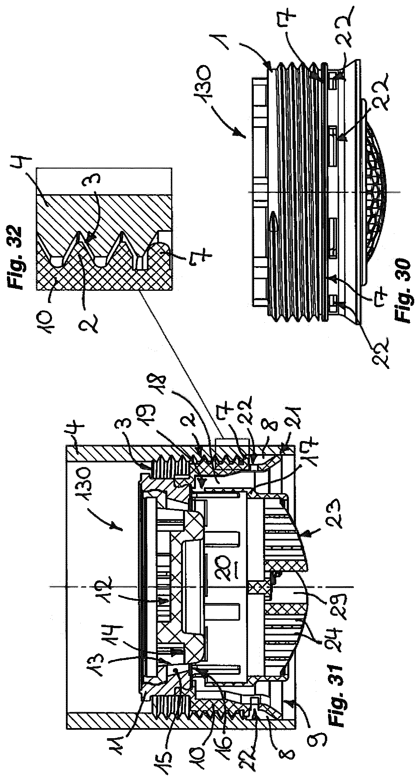
[0076] FIG. 30 shows a jet regulator in a side view, wherein the jet regulator shown here has a flange-like cross-sectional widening which is disposed above drainage openings and which extends around the outer circumference of the jet regulator housing,
[0077] FIG. 31 shows the jet regulator from FIG. 30 in a longitudinal section, and
[0078] FIG. 32 shows the screw connection provided between the outer thread on the jet regulator housing, on the one hand, and the inner thread in the water outlet, on the other hand, in a longitudinal section of a detail in the region of the cross-sectional widening disposed like a flange around the jet regulator housing.
DETAILED DESCRIPTION
[0079] FIGS. 1 to 32 show various embodiments 101, 104, 111, 115, 127 and 130 of a jet regulator. While only the jet regulator housing of the jet regulator 101 is illustrated, the jet regulators 104, 111, 115, 127 and 130 in FIGS. 6, 13, 22, 25, 28 and 31 are shown in longitudinal sections which in an exemplary manner show all essential component parts of such a jet regulator.
[0080] The jet regulators 101, 104, 111, 115, 127 and 130 shown here have a jet regulator housing 1 which, on its housing outer circumference, has an outer thread 2. With the outer thread 2 provided on the housing outer circumference, the jet regulators 101, 104, 111, 115, 127 and 130 can in each case be screwed into an inner thread 3 in the water outlet 4 of a sanitary outlet fitting so as to shape the water emerging there into a homogenous, non-sputtering and optionally also sparkling soft water jet. To ensure that the annular zone 5 remaining between the housing outer circumference of the jet regulator housing 1 and the inner circumference of the water outlet 4 is sealed off with respect to uncontrolled emergence of leakage water, the jet regulators 101, 104, 111 and 115 have as the outer thread 2 a thread profile which, at least in regions, deviates from a thread groove that extends continuously in a helical manner about a cylindrical wall. The outer thread 2, in this thread profile that at least in regions is designed in a deviating manner, interacts in a self-tapping or rather self-adapting manner with the inner thread 3 provided in the water outlet 4, in such a way that this screw connection provides particularly good sealing in this region. Additionally, or as here alternatively, at least one cross-sectional widening 6, 7 is provided respectively in the jet regulators 127 and 130, which cross-sectional widening 6, 7 is materially identical with the housing portion of the jet regulator housing that supports the outer thread 2 and is formed integrally thereon, and said cross-sectional widening 6, 7 can bear sealingly on the end face and/or inner circumferential face of the water outlet 4. By virtue of these particular design features of the jet regulators shown here, an uncontrolled emergence of leakage water through the annular zone 5 provided between the housing outer circumference of the jet regulator housing 1 and the inner circumference in the water outlet 4 is effectively avoided under almost all operating conditions, even when the jet regulators, as here, are designed without additional elastic sealing rings for axially or radially sealing the jet regulator housing 1. In the jet regulators 101, 104, 111, 115, 127 and 130, the abovementioned annular zone is reliably leaktight even when the inner thread 3 in the water outlet cannot be produced with high precision, and when the annular shoulder in the water outlet 4 required for the axial sealing is to be dispensed with in favor of lower manufacturing complexity in the production of the outlet fitting.
[0081] As is evident from the longitudinal sections in FIGS. 6, 13, 22, 25, 28 and 31, a housing end edge region of the jet regulator housing 1 disposed on the outflow side of the outer thread 2 is angled in the direction of the inner circumference of the water outlet 4 in such a way that a drainage annular space 8 is formed between this housing end edge region and the inner circumference of the water outlet 4.
[0082] The jet regulators 101, 104, 111, 115, 127 and 130 are here in each case configured as a jet aerator which mixes the water flowing therethrough with ambient air. The jet regulators 101, 104, 111, 115, 127 and 130 configured as jet aerators have at least one aeration opening 9 which is disposed on the outflow side of the outer thread 2 and is configured to be open toward the outflow-side housing end face.
[0083] The jet regulator housing 1 of the jet regulators 101, 104, 111, 115, 127 and 130 illustrated here has at least two housing parts 10, 11 which are releasably connectable to each other, of which a first housing part 10 disposed on the outflow side supports the outer thread 2. This outflow-side first housing part 10 is releasably connected at the inflow side to a second housing part 11 of the jet regulator housing 1, which second housing part 11 supports a jet splitter, which splits the water flowing therethrough into a multiplicity of individual jets.
[0084] The jet splitter of the jet regulator 111 shown in FIGS. 11 to 14 is configured here as a perforated plate 30 which has a multiplicity of splitter openings 31 and which is formed integrally in the second housing part 11. The splitter openings 31 situated in the perforated plate 30, which is oriented transversely to the flow direction, form cross-sectional constrictions which preferably taper in the flow direction and in which the inflowing water experiences an increase in velocity. Due to this increase in velocity, a negative pressure by which ambient air can be sucked into the housing interior of the jet regulator housing 1 is created on the outflow side of the perforated plate 30. In order for this ambient air to be intensively mixed with the water flowing through the housing interior, at least one insert part 32, 33 is provided on the outflow side of the perforated plate 30, at a distance from the latter, said insert parts having in each case a mesh or net structure composed of webs that intersect one another at intersection nodes. In the mesh or net structure of these insert parts 32, 33, the inflowing water is additionally divided in such a way that it can readily mix with the suctioned ambient air before said water, at the outlet end face of the jet regulator 111, is combined in a flow straightener so as to form a homogenous, non-sputtering and sparkling soft outlet jet.
[0085] By contrast, the jet splitter of the jet regulators 101, 104, 115, 127 and 130 is configured as a diffuser having a cup-shaped jet splitter insert 12 which, on the cup circumference of its cup shape, has a plurality of splitter openings 13, and which has a cup base 14 that is configured as an impact surface that deflects the inflowing water toward the splitter openings 13.
[0086] The second housing part 11 engages around the jet splitter insert 12 of the jet splitter. The second housing part 11, in terms of its clear housing cross section, conically tapers in such a way that an annular gap 15 is formed between the jet splitter insert 12 and the housing inner circumference of the second housing part 11, which annular gap 15 tapers on the outlet side toward an annular opening 16 that opens into the housing interior.
[0087] A sleeve-shaped guide wall 17 is provided in the jet regulator housing 1, at least one aeration duct 18 being provided between said guide wall 17 and the housing inner circumference of the jet regulator housing 1. This aeration duct 18 leads to the housing interior from the at least one aeration opening 9 disposed on the housing outflow face. Since the water divided into individual jets in the jet splitter experiences an increase in velocity in the annular gap 15, a negative pressure arises according to Bernoulli's principle on the outflow side of the annular gap 15 in the region of the annular opening 16, which negative pressure sucks ambient air from the outside through the aeration duct 18 into the sub-region of the housing interior that serves as a mixing zone 20. There, the water flowing through is mixed with the suctioned ambient air.
[0088] As can be readily seen from the longitudinal sections according to FIGS. 6, 13, 22, 25, 28 and 31, the housing sub-region or housing end edge region of the jet regulator housing 1 disposed on the outflow side of the outer thread 2 is angled in the direction of the inner circumference of the water outlet 4 in such a way that the drainage annular space 8 is formed between this housing end edge region and the inner circumference of the water outlet 4. To ensure that the leakage water seeping through the annular zone 5 between the housing outer circumference of the jet regulator housing 1 and the inner circumference of the water outlet 4 can be readily retained in the drainage annular space 8, the outflow-side housing end edge of the jet regulator housing 1 is configured as a lip seal 21 which could bear on the inner circumference of the water outlet 4, but which here only lies close to the inner circumference of the water outlet 4. Due to the capillary forces in this region, and on account of rapid furring in the annular gap between the housing end edge configured as the lip seal 21 and the inner circumference in the water outlet 4, said annular gap is additionally sealed off.
[0089] As can be seen in the longitudinal sections according to FIGS. 6, 13, 22, 25, 28 and 31, at least one drainage opening 22, which leads from the drainage annular space 8 to the aeration duct 18, is provided in the sub-region of the housing wall of the jet regulator housing 1 that is disposed between the outflow-side housing end edge and the outer thread 2. The air sucked through the aeration duct 18 can thus entrain the leakage water emerging from the drainage annular space 8 via the drainage openings 22 and can guide said leakage water into the housing interior, where said leakage water mixes with the water flowing therethrough.
[0090] A mesh or net structure 23 comprised of webs that intersect one another at intersection nodes is integrally formed on the guide wall 17 at the outflow side. The throughflow holes 24 of this mesh or net structure 23, which are formed between neighboring webs and which here have a honeycomb-shaped hexagonal clear hole cross section, preferably have a longitudinal extent that is larger in comparison to the hole cross section, but at least have a longitudinal extent that suffices for bringing the water mixed in the housing interior together into a homogenous water jet. The guide wall 17 is connected in a rotationally fixed and preferably integral manner to the jet regulator housing 1 and in particular to the outflow-side first housing part 10. At least one tool engagement face for a driving tool is provided here on the guide wall 17. For this purpose, at least one slit-shaped recess 29 for the insertion of a coin used as the driving tool, or of another driving tool, is provided in the mesh or net structure 23. This recess 29 is delimited by opposite slit longitudinal walls. These slit longitudinal walls of the recess 29 form tool engagement faces for the driving tool.
[0091] In order to configure the outer thread 2 with a thread profile that deviates from a thread groove extending continuously in a helical manner about a cylindrical wall, the outer envelope circle of the outer thread on the jet regulator housing that is intended for screwing into the inner thread 3 molded in the cylindrical water outlet 4 in the case of the jet regulator shown in FIGS. 1 to 3 widens conically toward the outflow side. In FIG. 2, the outer thread 2 configured conically toward the outflow side is shown in a position in which the jet regulator 101 is screwed into the inner thread. By virtue of the conicity of the outer thread 2, the uppermost thread turn on the inflow side still sits with some clearance in the inner thread 3, while the next-but-one thread turn in relation to the uppermost thread turn, on account of the conicity of the outer thread that begins there, protrudes deeper into the thread groove of the inner thread 3. The last thread turn at the outflow side of the outer thread 2 almost completely closes the assigned thread groove of the inner thread 3, such that leakage water can no longer seep through by way of this screw connection.
[0092] A further deviation of the thread profile forming the outer thread 2 is shown in the case of the jet regulator 104 according to FIGS. 4 to 10. In the case of this jet regulator, a cam-shaped molding 28 is configured on the outer thread 2 provided on the housing outer circumference and, in one of the thread grooves of the outer thread, extends approximately in the groove longitudinal direction. This cam-shaped molding 28 projects beyond the envelope circle enveloping the outer thread 2. When the outer thread 2 is screwed in the inner thread 3, the cam-shaped molding 28 seals in the groove base of the neighboring inner thread 3, on the flanks of this inner thread 3, and at the tip of the thread profile, once the cam-shaped molding 28 has cut deep into the inner thread 3.
[0093] A further deviation in the thread profile forming the outer thread 2 is implemented in the jet regulator 111 illustrated in FIGS. 11 to 14. In the jet regulator 111 too, at least one molding that serves as a liquids bulkhead and projects into at least one thread groove of the outer thread 2 is provided on the housing outer circumference of the jet regulator housing 1. However, this at least one molding is here configured as a separation wall 26 which extends across at least two thread grooves of the outer thread 2 and which runs approximately axially parallel to the housing longitudinal axis of the jet regulator housing 1. Since this molding configured as separation wall 26 projects far beyond the envelope circle enveloping the outer thread 2, this molding at the same time also represents a cross-sectional widening which projects beyond the adjacent regions of the jet regulator housing 1 and which is materially identical with the housing portion of the jet regulator housing 1 that supports the outer thread 2, and which is formed integrally thereon, and which bears sealingly on the inner circumferential face of the water outlet 4 and prevents seeping of leakage water via the screw connection.
[0094] Also in the case of the jet regulator 115 shown in FIGS. 15 to 26, the outer thread 2 is configured as a thread profile which at least in regions deviates from a thread groove extending continuously in a helical manner about a cylindrical wall. For this purpose, the thread profile of the outer thread, projecting beyond the thread groove, preferably widens in an outflow-side thread portion at least in regions and in this way forms a sealing wedge 27, which is illustrated in more detail in FIGS. 15 to 18. FIGS. 23A to 23C show how the molding of the thread profile forming the outer thread 2, configured as sealing wedge 27, cuts increasingly into the inner thread 3 of the outlet fitting as the outer thread 2 is screwed in. While the outer thread 2 in FIG. 23A is not yet completely screwed into the inner thread 3, and the molding configured as sealing wedge 27 has not yet been cut, FIG. 23B shows how this molding starts to increasingly cut into the inner thread 3 as the outer thread 2 is driven further into the latter. The jet regulator in FIG. 23C is completely assembled, and the molding configured as sealing wedge 27 is fully engaged with the inner thread 3. The overlapping hatched area in FIG. 23C indicates that the material of the molding provided in the outer thread 2 and/or of the inner thread 3 is displaced here.
[0095] On the basis of the jet regulators 127 and 130, it is shown that the jet regulator housing 1 can also have, on its housing outer circumference, at least one cross-sectional widening 6; 7 which is materially identical to the housing portion of the jet regulator housing 1 that supports the outer thread 2 and which is integrally formed thereon, and which can bear sealingly on the end face and/or inner circumferential face of the water outlet 4. These cross-sectional widenings 6; 7 in the case of the jet regulators 127 and 130 are configured like flanges and, in the housing circumferential direction of the jet regulator housing 1, extend across at least one of the drainage openings 22. The flange-like cross-sectional widenings 6; 7 on the housing outer circumference of the jet regulator housing 1 of the jet regulators 127, 130 are provided between the outer thread 2 and the at least one drainage opening 22. While the flange-like cross-sectional widenings 6 in the case of the jet regulator 127 shown in FIGS. 27 to 29 are in each case disposed on the inflow side directly above one of the drainage openings 22, the jet regulator 130 shown in FIGS. 30 to 32 by contrast has a flange-like cross-sectional widening 7 which is configured as an annular flange that encircles the jet regulator housing 1. The flange-like cross-sectional widenings 6; 7 on the jet regulators 127, 130 are here also configured as a screw-in abutment which limits the screwing of the outer thread 2 into the inner thread 3 in the water outlet 4 of the outlet fitting. The cross-sectional widenings can bear sealingly on the outlet end face or, as here, on the inner circumference of the water outlet.
[0096] The jet regulators shown here are distinguished by a high degree of sealing in the region of the annular zone 5 situated between the housing outer circumference of the jet regulator housing 1 and the inner circumference in the water outlet 4 of the outlet fitting, without separate and in particular materially dissimilar sealing rings seals being required for the sealing. The jet regulators 101, 104, 111, 115, 127 and 130 illustrated here are therefore configured free of a sealing ring and make do without a sealing ring of elastic material produced separately from the jet regulator housing 1.
LIST OF REFERENCE SIGNS
[0097] 1 Jet regulator housing [0098] 2 Outer thread [0099] 3 Inner thread [0100] 4 Water outlet [0101] 5 Annular zone [0102] 6 Flange-like cross-sectional widening (on the jet regulator 127 according to FIGS. 27 to 29) [0103] 7 Encircling flange-like cross-sectional widening (on the jet regulator 130 according to FIGS. 30 to 32) [0104] 8 Drainage annular space [0105] 9 Aeration opening [0106] 10 First outflow-side housing part [0107] 11 Second housing part [0108] 12 Jet splitter insert [0109] 13 Splitter openings [0110] 14 Cup base [0111] 15 Annular gap (in the jet splitter) [0112] 16 Annular opening (of the annular gap 15) [0113] 17 Guide wall [0114] 18 Aeration duct [0115] 19 Duct opening [0116] 20 Mixing zone [0117] 21 Lip seal [0118] 22 Drainage opening [0119] 23 Mesh or net structure [0120] 24 Throughflow openings [0121] 26 Separation wall [0122] 27 Sealing wedge [0123] 28 Cam-shaped molding [0124] 29 Recess [0125] 30 Perforated plate [0126] 31 Splitter openings [0127] 32 Insert part [0128] 33 Insert part [0129] 101 Jet regulator according to FIGS. 1 to 3 [0130] 104 Jet regulator according to FIGS. 4 to 10 [0131] 111 Jet regulator according to FIGS. 11 to 14 [0132] 115 Jet regulator according to FIGS. 15 to 26 [0133] 127 Jet regulator according to FIGS. 27 to 30 [0134] 130 Jet regulator according to FIGS. 30 to 32
* * * * *
D00000
D00001
D00002
D00003
D00004
D00005
D00006
D00007
D00008
D00009
D00010
XML
uspto.report is an independent third-party trademark research tool that is not affiliated, endorsed, or sponsored by the United States Patent and Trademark Office (USPTO) or any other governmental organization. The information provided by uspto.report is based on publicly available data at the time of writing and is intended for informational purposes only.
While we strive to provide accurate and up-to-date information, we do not guarantee the accuracy, completeness, reliability, or suitability of the information displayed on this site. The use of this site is at your own risk. Any reliance you place on such information is therefore strictly at your own risk.
All official trademark data, including owner information, should be verified by visiting the official USPTO website at www.uspto.gov. This site is not intended to replace professional legal advice and should not be used as a substitute for consulting with a legal professional who is knowledgeable about trademark law.