Method For Predicting Martensitic Transformation Rate And Method For Setting Processing Condition
YANAGIMOTO; Jun ; et al.
U.S. patent application number 16/731141 was filed with the patent office on 2020-07-16 for method for predicting martensitic transformation rate and method for setting processing condition. This patent application is currently assigned to The University of Tokyo. The applicant listed for this patent is The University of Tokyo TOYOTA JIDOSHA KABUSHIKI KAISHA. Invention is credited to Hiroyuki IKUTA, Takahiro ISHIGURO, Dai KOBUCHI, Kenshiro MIMURA, Jun YANAGIMOTO.
| Application Number | 20200224289 16/731141 |
| Document ID | / |
| Family ID | 71517453 |
| Filed Date | 2020-07-16 |


View All Diagrams
| United States Patent Application | 20200224289 |
| Kind Code | A1 |
| YANAGIMOTO; Jun ; et al. | July 16, 2020 |
METHOD FOR PREDICTING MARTENSITIC TRANSFORMATION RATE AND METHOD FOR SETTING PROCESSING CONDITION
Abstract
A method for predicting a martensitic transformation rate and a method for setting processing conditions capable of improving the accuracy of a prediction of a martensitic transformation rate when a steel material is subjected to deformation processing as well as to heat treatment are provided. A method for predicting a martensitic transformation rate according to an embodiment includes predicting a rate of a transformation to a martensitic phase that appears when a steel material is subjected to deformation processing as well as to heat treatment in which a temperature of the steel material is changed, in which a martensitic transformation rate Vm is calculated by using a prediction formula, the method further including identifying parameters m and n of the prediction formula, and calculating the martensitic transformation rate at a predetermined temperature and a predetermined strain rate by using the prediction formula into which the identified parameters are substituted.
| Inventors: | YANAGIMOTO; Jun; (Bunkyo-ku, JP) ; MIMURA; Kenshiro; (Toyota-shi, JP) ; KOBUCHI; Dai; (Nagoya-shi, JP) ; IKUTA; Hiroyuki; (Nisshin-shi, JP) ; ISHIGURO; Takahiro; (Chiryu-shi, JP) | ||||||||||
| Applicant: |
|
||||||||||
|---|---|---|---|---|---|---|---|---|---|---|---|
| Assignee: | The University of Tokyo Bunkyo-ku JP TOYOTA JIDOSHA KABUSHIKI KAISHA Toyota-shi JP |
||||||||||
| Family ID: | 71517453 | ||||||||||
| Appl. No.: | 16/731141 | ||||||||||
| Filed: | December 31, 2019 |
| Current U.S. Class: | 1/1 |
| Current CPC Class: | C21D 2211/008 20130101; C21D 11/00 20130101; C21D 9/32 20130101 |
| International Class: | C21D 11/00 20060101 C21D011/00; C21D 9/32 20060101 C21D009/32 |
Foreign Application Data
| Date | Code | Application Number |
|---|---|---|
| Jan 10, 2019 | JP | 2019-002574 |
Claims
1. A method for predicting a martensitic transformation rate comprising predicting a rate of a transformation to a martensitic phase that appears when a steel material is subjected to deformation processing as well as to heat treatment in which a temperature of the steel material is changed, wherein a martensitic transformation rate V.sub.m in calculated by using a below-shown Expression (1): V n = ( 1 - V .alpha. - V p - V .beta. ) [ { 1 - exp [ - 0 . 0 1 1 ( M S - T ) ] } + .alpha. i = t o t n ( . i * ) n ] ( .rho. .rho. 0 ) m ( 1 ) ##EQU00007## where: V.sub..alpha. is a ferrite rate; V.sub.p is a pearlite rate; V.sub..beta. is a bainite rate; and M.sub.S satisfies a below-shown Expression (2): M.sub.S=550-350.times.[C]%-40.times.[Mn]%-35.times.[V]%-20.times.[Cr]% (2) where: T is a temperature in the heat treatment; .epsilon..sub.i with a dot (i.e., .epsilon..sub.i with " " added thereon) is a strain rate of the steel material; .epsilon.* is a normalization constant; t.sub.0 is a start time of the deformation processing; t.sub.n is an end time of the deformation processing; .rho. is an average dislocation density of the steel material; .rho..sub.0 is an initial dislocation density of the steel material; and .alpha., m and n are parameters.
2. The method for predicting a martensitic transformation rate according to claim 1, comprising: identifying the parameters .alpha., m and n of the Expression (1); and calculating the martensitic transformation rate at a predetermined temperature and a predetermined strain rate by using the Expression (1) into which the identified parameters .alpha., m and n are substituted.
3. The method for predicting a martensitic transformation rate according to claim 2, wherein the identifying the parameters .alpha., m and n of the Expression (1) comprises: obtaining a measured value of the martensitic transformation rate by performing a compression test of the steel material; calculating the martensitic transformation rate from the Expression (1) in which the parameters are changed; and comparing the measured value with the calculated value, and identifying, as the parameters .alpha., m and n of the Expression (1), parameters with which an error between the measured value and the calculated value falls within a predetermined range.
4. A method for setting a processing condition, comprising setting a temperature and a strain rate at the time when the steel material is subjected to the deformation processing by using the method for predicting a martensitic transformation rate according to claim 2 so that the resultant steel material has a predetermined martensitic transformation rate.
5. The method for setting a processing condition according to claim 4, wherein the steel material is a material for a gear, the deformation processing is performed by a rotating die, and when the strain rate is set, a rotation condition of the die for forming a predetermined part of the gear is set.
Description
CROSS REFERENCE TO RELATED APPLICATIONS
[0001] This application is based upon and claims the benefit of priority from Japanese patent application No. 2019-002574, filed on Jan. 10, 2019, the disclosure of which is incorporated herein in its entirety by reference.
BACKGROUND
[0002] The present disclosure relates to a method for predicting a martensitic transformation rate and a method for setting processing conditions in a steel material processing process.
[0003] As a calculation formula for calculating a martensitic transformation rate in heat treatment of a steel material, there is a calculation formula disclosed in Magee, C. L. (for example, The Nucleation of Martensite, Ch. 3. ASM, New York, 1968., Materials Science Research International, Vol. 3, No. 4 pp. 193-203, 1997., ISIJ International, Vol. 32 No. 3, pp. 306-315, 1992. etc).
SUMMARY
[0004] It has been demonstrated that when the calculation formula disclosed in Magee, C. L. is used, predicted transformation rates of a steel material in the so-called static heat treatment roughly agree with actual behavior of the steel material. This is because the temperature dependence of the transformation becomes dominant in the static heat treatment. In contrast, predicted transformation rates in a process in which deformation processing of a steel material is combined with heat treatment thereof (e.g., a component rolling process of a gear material) widely differ from actual behavior of the steel material. It is considered that this is because the calculation formula disclosed in Magee, C. L. does not take account of the so-called dynamic factors, such as changes in energy caused by the deformation processing, in the occurrence of the transformation.
[0005] The present disclosure has been made in order to solve the above-described problem and provides a method for predicting a martensitic transformation rate and a method for setting processing conditions capable of improving the accuracy of a prediction of a martensitic transformation rate when a steel material is subjected to deformation processing as well as to heat treatment as compared with the prior-art calculation method.
[0006] In a first exemplary aspect, a method for predicting a martensitic transformation rate is a method for predicting a rate of a transformation to a martensitic phase that appears when a steel material is subjected to deformation processing as well as to heat treatment in which a temperature of the steel material is changed, in which a martensitic transformation rate is calculated by using a prediction formula. By adopting the above-described feature, it is possible to improve the accuracy of a prediction of a martensitic transformation rate when a steel material is subjected to deformation processing as well as to heat treatment as compared with the prior-art calculation method.
[0007] Further, another exemplary aspect is a method for setting a processing condition, in which a temperature and a strain rate at the time when a steel material is subjected to deformation processing are set by using a method for predicting a martensitic transformation rate so that the resultant steel material has a predetermined martensitic transformation rate. By adopting the above-described feature, it is possible to process a steel material into one having a desired martensitic transformation rate and thereby to make each part of the steel material have a different strength.
[0008] According to the present disclosure, it is possible to provide a method for predicting a martensitic transformation rate and a method for setting processing conditions capable of improving the accuracy of a prediction of a martensitic transformation rate when a steel material is subjected to deformation processing as well as to heat treatment as compared with the prior-art calculation method.
[0009] The above and other objects, features and advantages of the present disclosure will become more fully understood from the detailed description given hereinbelow and the accompanying drawings which are given by way of illustration only, and thus are not to be considered as limiting the present disclosure.
BRIEF DESCRIPTION OF DRAWINGS
[0010] FIG. 1 is a graph showing an example of a shift of a transformation nose caused by deformation processing in a martensitic transformation rate prediction formula according to a first embodiment, in which a horizontal axis indicates time and a vertical axis indicates temperatures;
[0011] FIG. 2 is a flowchart showing an example of a method for predicting a martensitic transformation rate according to an embodiment;
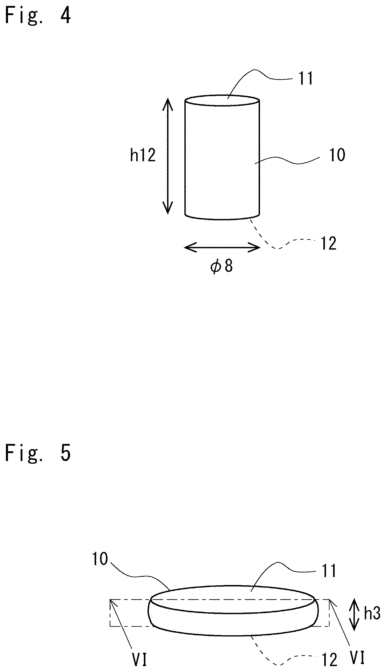
[0012] FIG. 3 is a flowchart showing an example of a method for identifying parameters of a prediction formula in a method for predicting a martensitic transformation rate according to an embodiment;
[0013] FIG. 4 shows an example of an unprocessed workpiece in a compression test in a method for predicting a martensitic transformation rate according to an embodiment;
[0014] FIG. 5 shows an example of a processed workpiece in a compression test in a method for predicting a martensitic transformation rate according to an embodiment;
[0015] FIG. 6 shows an example of a cross section of a processed workpiece in a compression test in a method for predicting a martensitic transformation rate according to an embodiment;
[0016] FIG. 7 shows an example of an actually-measured structure on a cross section of a workpiece compressed at a high temperature in a method for predicting a martensitic transformation rate according to an embodiment;
[0017] FIG. 8 is a calculation result showing an example of martensitic transformation rates on a cross section of a workpiece compressed at a high temperature, predicted by using a prediction formula in a method for predicting a martensitic transformation rate according to an embodiment;
[0018] FIG. 9 is a graph showing an example of calculated values of martensitic transformation rates on a cross section of a workpiece compressed at a high temperature, predicted by using a prediction formula in a method for predicting a martensitic transformation rate according to an embodiment, calculated values of martensitic transformation rates predicted by using an existing formula, and actually-measured values of martensitic transformation rates, in which a horizontal axis indicates distances from the upper surface of the workpiece and a vertical axis indicates martensitic transformation rates;
[0019] FIG. 10 shows an example of an actually-measured structure on a cross section of a workpiece compressed at a low temperature in a method for predicting a martensitic transformation rate according to an embodiment;
[0020] FIG. 11 is a calculation result showing an example of martensitic transformation rates on a cross section of a workpiece compressed at a low temperature, predicted by using a prediction formula in a method for predicting a martensitic transformation rate according to an embodiment;
[0021] FIG. 12 is a graph showing an example of calculated values of martensitic transformation rates on a cross section of a workpiece compressed at a low temperature, predicted by using a prediction formula in a method for predicting a martensitic transformation rate according to an embodiment, calculated values of martensitic transformation rates predicted by using an existing formula, and actually-measured values of martensitic transformation rates, in which a horizontal axis indicates distances from the upper surface of the workpiece and a vertical axis indicates martensitic transformation rates;
[0022] FIG. 13 shows an example of needs for gears of EVs (Electric Vehicles); and
[0023] FIG. 14 shows an example as to how to make each part of a gear have a different strength in a method for predicting a martensitic transformation prediction rate according to an embodiment.
DESCRIPTION OF EMBODIMENTS
[0024] Specific embodiments for implementing the present disclosure will be described hereinafter with reference to the drawings. However, the present disclosure is not limited to the below-shown embodiments. Further, the following descriptions and drawings are simplified as appropriate for clarifying the explanation.
Embodiment
[0025] A method for predicting a martensitic transformation rate according to an embodiment will be described. The method for predicting a martensitic transformation rate will be described hereinafter by dividing it into a <Prediction Formula> section, a <Method for Predicting Martensitic Transformation Rate> section, and a <Method for Setting Processing Conditions> section. In the <Prediction Formula> section, a prediction formula used for predicting a martensitic transformation rate will be described. Further, a comparison of this prediction formula with an existing formula will also be described. In the <Method for Predicting Martensitic Transformation Rate> section, a method for predicting a martensitic transformation rate by using the prediction formula will be described. In the <Method for Setting Processing Conditions> section, a method for setting processing conditions by using the method for predicting a martensitic transformation rate will be described.
[0026] <Prediction Formula>
[0027] A method for predicting a martensitic transformation rate according to this embodiment is a method for predicting a rate of a transformation to a martensitic phase that appears when a steel material is subjected to deformation processing as well as to heat treatment in which the temperature of the steel material is changed, and in which a martensitic transformation rate V.sub.m is calculated by using a prediction formula expressed by the below-shown Expression (1).
[ Expression 1 ] y m = ( 1 - V .alpha. - V p - V .beta. ) [ { 1 - exp [ - 0 . 0 1 1 ( M S - T ) ] } + .alpha. i = t o t n ( . i * ) n ] ( .rho. .rho. 0 ) m ( 1 ) ##EQU00001##
[0028] In the expression, V.sub..alpha. is a ferrite rate and V.sub.p is a pearlite rate. Further, V.sub..beta. is a bainite rate. For example, each of the martensitic transformation rate V.sub.m, the ferrite rate V.sub.u, the pearlite rate V.sub.p, and the bainite rate V.sub..beta. is a volume fraction. M.sub.S satisfies the below-shown Expression (2).
[Expression 2]
M.sub.S=.sub.550-350.times.[C]%-40.times.[Mn]%-35.times.[V]%-20.times.[C- r]% (2)
[0029] T is a temperature in the heat treatment; .epsilon..sub.i with a dot (i.e., .epsilon..sub.i with "-" added thereon, hereinafter expressed as .epsilon. .sub.i) is a strain rate of the steel material; .epsilon.* is a normalization constant [/s]; to is a start time of the deformation processing; t.sub.n is an end time of the deformation processing; .rho. is an average dislocation density of the steel material; .rho..sub.0 is an initial dislocation density of the steel material; .alpha. is a material constant; m is a dislocation dependence index; n is a strain-rate dependence index; and .alpha., m and n are parameters dependent on the temperature and the strain rate.
[0030] The ferrite rate V.alpha. is calculated by the below-shown Expressions (3) to (5) as shown in, for example, M. Suehiro et al. (M. Suehiro, K. Sato, H. Yada, T. Senuma and Y. Matsumura: Transactions ISIJ, 27 (1987), 439.), T. Senuma et al. (T. Senuma, M. Suehiro and H. Yada, ISIJ, Int., 32-3 (1992), 423.), J. Liu et al. (J. Liu, A. Yanagida, S. Sugiyama and J. Yanagimoto; ISIJ, Int., 41-12 (2001), 1510.)
[ Expression 3 ] V .alpha. = .intg. 0 .DELTA. X f dt ( 3 ) [ Expression 4 ] .DELTA. X F ( n ) = k 1 S v 2 G F n ( 1 - X F n - 1 ) .DELTA. t n ( 4 ) [ Expression 5 ] G F n = 1 2 r n D n C .gamma..alpha. n - C .gamma. n - 1 C .gamma. n - 1 C .alpha..gamma. n ( 5 ) ##EQU00002##
[0031] The pearlite rate V.sub.p is calculated by, for example, the below-shown Expressions (6) to (8) as shown in M. Suehiro et al.
[Expression 6]
V.sub.p=.intg..sub.0.sup.t.DELTA.X.sub.pdt (6)
[Expression 7]
.DELTA.X.sub.p.sup.<n>=k.sub.4S.sub.v2G.sub.p.sup.<n>(1-X.su- b.P.sup.<n-1>-X.sub.F.sup.total).DELTA.t.sup.<n> (7)
[Expression 8]
G.sub.P.sup.<n>=.DELTA.T.sup.<n>D.sup.<n>(C.sub..gamma- ..alpha..sup.<n>-C.sub..gamma..beta..sup.<n>) (8)
[0032] The bainite rate V.sub..beta. is calculated by, for example, the below-shown Expressions (9) to (11) as shown in M. Suehiro et al.
[Expression 9]
V.sub..beta.=.intg..sub.0.sup.t.DELTA.X.sub.Bdt. (9)
[Expression 10]
.DELTA.X.sub.B.sup.<n>=k.sub.5S.sub.v2G.sub.B.sup.<n>(1-X.su- b.B.sup.<n-1>-X.sub.F.sup.total-X.sub.P.sup.total).DELTA.t.sup.<n- > (10)
[Expression 11]
B.sub.S(.degree. C.)=717.5-425[C](wt %)-42.5[Mn](wt %) (11)
[0033] The coefficients have, for example, values shown in the below-shown Expression (12) as shown in J. Liu et al. The unit for these coefficients is (Cal.sup.3/mol.sup.3).
[ Expression 12 ] k 1 = 8.933 .times. 10 - 12 exp ( 21100 T ) k 2 = 17476.0 k 3 = 1.305 .times. 10 7 k 4 = 3.0 .times. 10 3 k 5 = 6.816 .times. 10 - 4 exp ( 3431.5 T ) } ( 12 ) ##EQU00003##
[0034] The below-shown Expression (13) shows nucleation caused by deformation energy.
[ Expression 13 ] .alpha. i = t 0 t n ( . i * ) n ( 13 ) ##EQU00004##
[0035] The above-shown Expression (13) is a Zener-Hollomon parameter. Therefore, it corresponds to the below-shown Expression (14) describing dynamic recrystallization behavior.
[ Expression 14 ] Z = . exp ( Q RT ) ( 14 ) ##EQU00005##
[0036] The above-shown Expression (14) indicates that nucleation occurs accidentally depending on the strain rate. The "exp" term can be expressed, for example, as "a", i.e., as a temperature dependence constant.
[0037] The below-shown Expression (15) indicates a shift of a transformation nose. Note that the initial dislocation density .rho..sub.0 is about 10.sup.8/cm.sup.2 (.rho..sub.0.apprxeq.10.sup.8/cm.sup.2).
[ Expression 14 ] ( .rho. .rho. 0 ) m ( 14 ) ##EQU00006##
[0038] FIG. 1 is a graph showing an example of a shift of a transformation nose caused by deformation processing in a martensitic transformation rate prediction formula according to a first embodiment, in which a horizontal axis indicates time and a vertical axis indicates temperatures. As shown in FIG. 1, when the temperature of the steel material is changed during the deformation processing thereof, the phase state of the steel material changes according to the temperature. For example, the phase of the steel material is a single phase of y-iron at 980.degree. C. or higher. Further, the phase becomes a two-phase state including 7-iron between 780.degree. C. and 980.degree. C. The above-shown Expression (15) indicates that the dislocation has a function of shifting the transformation nose in the non-martensitic region.
[0039] Next, an existing formula is described. The existing formula is the below-shown Expression (16) as shown in Magee, C. L.
[Expression 16]
V.sub.m=(1-V.sub..alpha.-V.sub.p-V.sub..beta.){1-exp[-0.011(M.sub.S-T)]} (16)
[0040] As compared with the prediction formula, the existing formula does not include the terms shown in the above-shown Expressions (13) and (15). In the case of static heat treatment, i.e., heat treatment that does not include deformation processing, i.e., includes only raising the temperature and cooling, it is possible to accurately predict a martensitic transformation rate by using the existing formula. This is because in the static heat treatment, the appearance of the martensitic phase is significantly dependent on the temperature.
[0041] In contrast, in the case of dynamic heat treatment, i.e., heat treatment that includes deformation processing, the appearance of the martensitic phase is dependent on nucleation caused by deformation energy and the shift of the transformation nose as well as dependent on the temperature. Therefore, in the dynamic heat treatment, it is impossible to accurately predict a martensitic transformation rate by using the existing formula. This is because neither the above-described nucleation caused by deformation energy nor the shift of the transformation nose is taken into account in the existing formula.
[0042] The terms shown in the above-shown Expressions (13) and (15) are added (i.e., included) in the prediction formula according to this embodiment. Therefore, the nucleation caused by deformation energy and the shift of the transformation nose are also taken into account in the prediction formula according to this embodiment. Therefore, it is possible to accurately predict a martensitic transformation rate in dynamic heat treatment.
[0043] <Method for Predicting Martensitic Transformation Rate>
[0044] Next, a method for predicting a martensitic transformation rate according to this embodiment is described. FIG. 2 is a flowchart showing an example of a method for predicting a martensitic transformation rate according to the embodiment. FIG. 3 is a flowchart showing an example of a method for identifying parameters of a prediction formula in the method for predicting a martensitic transformation rate according to the embodiment. FIG. 4 shows an example of an unprocessed workpiece (i.e., a workpiece that has not yet been processed) in a compression test in the method for predicting a martensitic transformation rate according to the embodiment. FIG. 5 shows an example of a processed workpiece (i.e., a workpiece that has already been processed) in a compression test in the method for predicting a martensitic transformation rate according to the embodiment. FIG. 6 shows an example of a cross section of the processed workpiece in the compression test in the method for predicting a martensitic transformation rate according to the embodiment, and shows a cross section taken along a line VI-VI in FIG. 5.
[0045] In order to predict a martensitic transformation rate, first of all, parameters .alpha., m and n of the prediction formula are identified (i.e., determined) as shown in a step S11 in FIG. 2. In order to identify the parameters .alpha., m and n of the prediction formula, firstly, a cylindrical compression test of a workpiece is performed as shown in a step S21 in FIG. 3.
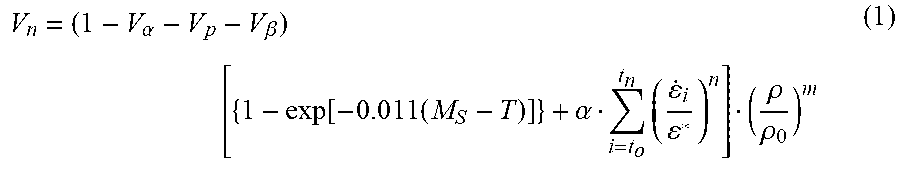
[0046] As shown in FIG. 4, a workpiece 10 used in the cylindrical compression test is a cylindrical steel material of which a diameter of a bottom surface (i.e., a diameter of the upper surface 11 and the lower surface 12) is 8 (mm) and a height is 12 (mm). The above-described workpiece 10 is deformed by applying a stress to each of the bottom surfaces (i.e., the upper and lower surfaces) so as to compress the workpiece 10. As a result, the workpiece 10 is deformed into a cylinder having a height of 3 (mm) as shown in FIG. 5. Then, as shown in FIG. 6, the deformed workpiece 10 is vertically severed at the center, so that a cross section of the workpiece 10 perpendicular to the bottom surface thereof is exposed.
[0047] Next, as shown in a step S22 in FIG. 3, hardness in the central part on the cross section of the workpiece 10 is measured. When the hardness is measured, the cross section is divided into minute parts in a mesh pattern and hardness of each minute part is measured. Next, as shown in a step S23, the measured hardness of each minute part on the cross section is converted into a martensitic transformation rate. For example, the measured hardness is converted into a martensitic transformation rate by using a degree of a strain obtained based on the measured hardness and the crystalline structure. By doing so, a distribution of martensitic transformation rates on the cross section is obtained. In this way, measured values of martensitic transformation rates are obtained by performing the compression test of the steel material in the steps S21 to S23.
[0048] Meanwhile, a cylindrical compression analysis is performed as shown in a step S24. In the cylindrical compression analysis, martensitic transformation rates are calculated by using the prediction formula. In this process, martensitic transformation rates are calculated for a plurality of parameters .alpha., m and n as shown in a step S26 while changing the parameters .alpha., m and n as shown in a step S25. When the martensitic transformation rates are calculated, the workpiece 10 is divided into minute parts in a mesh pattern and a martensitic transformation rate is calculated for each minute part by using a strain rate of that minute part. For example, the strain rate is derived from the processing speed of the cylindrical compression. Specifically, the strain rate is calculated by summing up strain rates in respective minute time periods from a time to at which the processing is stared to a time t, at which the processing is finished. In this way, through the steps S24 to S26, calculated values of martensitic transformation rates are obtained by the prediction formula in which the parameters .alpha., m and n are changed.
[0049] Note that the steps S24 to S26 may be performed after the steps S21 to S23, or the steps S21 to S23 may be performed after the steps S24 to S26. Alternatively, the steps S24 to S26 may be performed in parallel with the steps S21 to S23.
[0050] Next, as shown in a step S27, the measured value of the martensitic transformation rate is compared with the calculated value. Then, for example, when an error (i.e., a difference) between these values exceeds a predetermined range, the process returns to the step S25, in which the parameters .alpha., m and n are changed. Further, the steps S26 and S27 are repeated. On the other hand, when the error between these values is within the predetermined range in the step S27, the parameters at that time are identified (i.e., determined) as the parameters .alpha., m and n of the prediction formula. Note that the predetermined range for the error between these values is, for example, 10%. However, the predetermined range is not limited to this example.
[0051] Next, as shown in a step S12 in FIG. 2, a martensitic transformation rate at a predetermined temperature and a predetermined strain rate is calculated by using the prediction formula into which the identified parameters .alpha., m, and n have been substituted. In this way, it is possible to predict a rate of a transformation of the steel material to the martensitic phase, which appears when the steel material is subjected to deformation processing as well as to heat treatment in which the temperature of the steel material is changed.
[0052] Martensitic transformation rates that are obtained after subjecting the steel material to deformation processing at high and low temperatures are compared by using the prediction formula according to this embodiment and the existing formula. The deformation processing at the high temperature is, for example, deformation processing performed at a temperature of 1,050 [.degree. C.] and a strain rate of 50 [/s]. The deformation processing at the high temperature is significantly dependent on the temperature. Therefore, such deformation processing corresponds to a static heat treatment state. When the deformation processing corresponds to the static heat treatment, it is possible to predict martensitic transformation rates by using the existing formula.
[0053] FIG. 7 shows an example of an actually-measured structure on a cross section of a workpiece compressed at a high temperature in the method for predicting a martensitic transformation rate according to the embodiment. FIG. 8 is a calculation result showing an example of martensitic transformation rates on a cross section of a workpiece compressed at a high temperature, predicted by using the prediction formula in the method for predicting a martensitic transformation rate according to the embodiment. FIG. 9 is a graph showing an example of calculated values of martensitic transformation rates on a cross section of a workpiece compressed at a high temperature, predicted by using the prediction formula in the method for predicting a martensitic transformation rate according to the embodiment, calculated values of martensitic transformation rates predicted by using the existing formula, and actually-measured values of martensitic transformation rates, in which a horizontal axis indicates distances from the upper surface of the workpiece and a vertical axis indicates martensitic transformation rates.
[0054] As shown in FIG. 7, the measured values are derived by measuring hardness on the cross section of the workpiece 10. Specifically, the measured values are obtained in the steps S22 and S23. As shown in FIG. 8, the calculated values of the prediction formula are obtained in the steps S24 to S26. A distribution of martensitic transformation rates on the cross section of the workpiece 10 are shown in a gray scale. As shown in FIG. 9, the measured value of the martensitic transformation rate near the upper surface is 0.8. In a range of distances from 0 (mm) to 2 (mm) as measured from the upper surface, the martensitic transformation rate slightly increases while oscillating between 0.7 and 0.85. In a range of distances from 2 (mm) to 3 (mm), the martensitic transformation rate slightly increases from 0.85 to 0.94.
[0055] Regarding the calculated value by the prediction formula according to this embodiment, the martensitic transformation rate near the upper surface is 0.75. In a range of distances from 0 (mm) to 0.5 (mm) as measured from the upper surface, the martensitic transformation rate slightly increases. In a range of distances from 0.5 (mm) to 3 (mm), the martensitic transformation rate is roughly constant (i.e., unchanged) at 0.85.
[0056] Regarding the calculated value by the existing formula, the martensitic transformation rate near the upper surface is 0.8. In a range of distances from 0 (mm) to 0.5 (mm) as measured from the upper surface, the martensitic transformation rate slightly decreases. In a range of distances from 0.5 (mm) to 3 (mm), the martensitic transformation rate is roughly constant (i.e., unchanged) at 0.75.
[0057] As described above, in the deformation processing at a high temperature, the prediction formula according to this embodiment satisfactorily agrees with measured values of martensitic transformation rates. Therefore, the prediction formula according to this embodiment can predict the martensitic transformation rate in the deformation processing at a high temperature. Further, since the deformation processing at a high temperature corresponds to static heat treatment, which is significantly dependent on the temperature, the martensitic transformation rate can also be predicted by the existing formula as well as by the prediction formula according to this embodiment.
[0058] Meanwhile, the deformation processing at the low temperature is, for example, deformation processing performed at a temperature of 750 (.degree. C.) and a strain rate of 50 (/s). The deformation processing at the low temperature is not significantly dependent on the temperature. Therefore, such deformation processing corresponds to a dynamic heat treatment. In the case of the dynamic heat treatment, it is impossible to predict the martensitic transformation rate by using the existing formula.
[0059] FIG. 10 shows an example of an actually-measured structure on a cross section of a workpiece compressed at a low temperature in the method for predicting a martensitic transformation rate according to the embodiment. FIG. 11 is a calculation result showing an example of martensitic transformation rates on a cross section of a workpiece compressed at a low temperature, predicted by using the prediction formula in the method for predicting a martensitic transformation rate according to the embodiment. FIG. 12 is a graph showing an example of calculated values of martensitic transformation rates on a cross section of a workpiece compressed at a low temperature, predicted by using the prediction formula in the method for predicting a martensitic transformation rate according to the embodiment, calculated values of martensitic transformation rates predicted by using the existing formula, and actually-measured values of martensitic transformation rates, in which a horizontal axis indicates distances from the upper surface of the workpiece and a vertical axis indicates martensitic transformation rates.
[0060] As shown in FIG. 10, the measured values are derived by measuring hardness on the cross section of the workpiece 10. Changes in the structure are observed in the central part on the cross section shown in FIG. 10. As shown in FIG. 11, calculated values of the prediction formula is shown in a gray scale. Changes in the martensitic transformation rate are observed in the central part on the cross section of the workpiece 10.
[0061] As shown in FIG. 12, the measured value of the martensitic transformation rate near the upper surface is 0.05. In a range of distances from 0 (mm) to 1.6 (mm) as measured from the upper surface, the martensitic transformation rate fluctuates around or below 0.1. The martensitic transformation rate sharply increases at the distance of 1.6 (mm) and has a peak value of 0.9 at a distance of 1.75 (mm). The martensitic transformation rate sharply decreases at a distance of 2 (mm) and fluctuates around 0.1 in a range of distances from 2 (mm) to 3 (mm).
[0062] Regarding the calculated value by the prediction formula according to this embodiment, the martensitic transformation rate near the upper surface is 0. In a range of distances from 0 (mm) to 1.5 (mm) as measured from the upper surface, the martensitic transformation rate slightly increases to 0.2. The martensitic transformation rate sharply increases at the distance of 1.6 (mm) and has a peak value of 0.85 at a distance of 1.75 (mm). The martensitic transformation rate sharply decreases at a distance of 2 (mm) and decreases to 0.1 in a range of distances from 2 (mm) to 3 (mm).
[0063] Regarding the calculated value by the existing formula, the martensitic transformation rate near the upper surface is 0.87. In a range of distances from 0 (mm) to 1.0 (mm) as measured from the upper surface, the martensitic transformation rate decreases to 0.5. In a range of distances from 1.0 (mm) to 2.5 (mm), the martensitic transformation rate fluctuates around 0.45. In a range of distances from 2.5 (mm) to 3.0 (mm), the martensitic transformation rate increases to 0.65.
[0064] As described above, in the case of the deformation processing at a low temperature, the prediction formula according to this embodiment satisfactorily agrees with measured values of martensitic transformation rates. For example, the prediction formula can reproduce behavior in which the martensitic transformation rate increases in the central part between the upper surface 11 of the workpiece 10 and the lower surface 12 thereof. Therefore, the prediction formula can accurately predict martensitic transformation rates in the deformation processing at a low temperature. In contrast, in the deformation processing at a low temperature, since the transformation is not significantly dependent on the temperature, it is impossible to predict the martensitic transformation rate by using the existing formula. For example, the existing formula cannot reproduce the behavior in which the martensitic transformation rate increases in the central part of the workpiece.
[0065] In principle, no martensitic phase appears when only heat treatment at 750.degree. C. is performed. In order to form a martensitic phase, heat treatment at 900.degree. C. or higher has to be performed to form austenite in which carbon or the like is contained in the form of solid solution in y-iron having an fcc structure. By cooling the austenite, a martensitic phase having a bct structure in which carbon is contained in the form of solid solution in a bcc structure appears.
[0066] In contrast, in heat treatment at 750.degree. C. in which deformation processing is also performed, a crystal lattice is distorted due to energy of the deformation processing. Further, carbon enters the distorted crystal lattice. Part of the carbon that has entered the distorted crystal lattice and has not escaped therefrom is trapped therein after the deformation processing. Further, it is considered that it consequently transforms into martensite. Since such a martensitic transformation is not taken into account in the existing formula, it cannot predict a martensitic transformation rate.
[0067] The deformation processing at a low temperature has the following advantages. That is, the oxidation of the steel material can be quantitatively reduced. Further, the thermal expansion of the steel material can be quantitatively reduced. Further, the residual T-iron can be reduced. Therefore, the deformation processing at a low temperature is becoming more important as a method for processing a component made of a steel material. The prediction formula according to this embodiment can be applied to such important processing methods.
[0068] According to the method for predicting a martensitic transformation rate in accordance with this embodiment, it is possible to improve the accuracy of a prediction of a martensitic transformation rate when a steel material is subjected to deformation processing as well as to heat treatment as compared with the prior-art calculation method. In particular, in the case of the deformation processing at a low temperature, which corresponds to the dynamic heat treatment, while the existing formula cannot predict the martensitic transformation rate, the prediction formula according to this embodiment can predict the martensitic transformation rate.
[0069] <Method for Setting Processing Condition>
[0070] Next, a method for setting processing conditions to which the method for predicting a martensitic transformation rate according to this embodiment is applied is described. In the method for setting processing conditions according to this embodiment, a temperature and a strain rate at the time when a steel material is subjected to deformation processing are set by using the above-described method for predicting a martensitic transformation rate so that the resultant steel material has a predetermined martensitic transformation rate. The method for setting processing conditions according to this embodiment is applied to, for example, the setting of processing conditions for strengthening a gear. Due to the needs from EVs (Electric Vehicles) and their systems, a gear strengthening technique is essential for gears in order to achieve a reduction in size and an improvement in efficiency.
[0071] FIG. 13 shows an example of needs for gears of EVs (Electric Vehicles). As shown in FIG. 13, as needs for vehicles and their systems, for example, it has been desired to reduce the amount (or the number) of batteries mounted in the vehicle and increase the power efficiency (i.e., the electric mileage). To that end, there is a need to reduce rolling losses of tires and it has been desired to lower the position of the center of gravity, reduce the size, and reduce the difference between the weight on the left wheel and that on the right wheel. Further, there is a need to reduce a T/A loss and it has been desired to improve the efficiency. Further, there is a need for easiness for mounting and it has been desired to reduce the size.
[0072] In order to achieve the above-described low position of the center of gravity, the reduction in the difference between weights on the left and right wheels, the high efficiency, and the reduction in size, as needs for the T/A, it has been desired to reduce the height, reduce the width, reduce the weight, lower the viscosity of oil, reduce the volume of lubricating oil, facilitate the conversion into ball bearings, and reduce the length. Further, all of these needs for the T/A are directly related to the strengthening of gears.
[0073] As a method for strengthening a gear, there is a method for forming a gear out of a high-strength material. However, if this method is implemented as the extension of the prior art, there is a limit to the achieved strength. Further, if the whole part of a gear is strong, its torsional rigidity (dynamic rigidity) becomes so high that it adversely affects its vibration. Therefore, it is necessary to strengthen only a part(s) of a gear where strength is required and make the other parts have tenacity. That is, it is necessary to change the strength of each part of the gear according to the place of that part in the gear.
[0074] FIG. 14 shows an example as to how to make each part of a gear have a different strength in a method for predicting a martensitic transformation prediction rate according to an embodiment. As shown in FIG. 14, a tooth surface 21 of a gear 20 in which the tooth of the gear 20 comes into contact with that of another gear needs to be strong. Further, a tooth base 22 of the gear 20 at which the tooth is bent also needs to be strong. Meanwhile, a central part 23 of the tooth needs to have tenacity rather than strength.
[0075] Since it is necessary to change the strength of each part of the gear 20 according to the place of that part as described above, it is necessary to perform thermo-mechanical heat treatment in which the strengthening of the material by deformation processing is combined with the strengthening thereof by heat treatment. As a result, it is possible to aim to develop strengths that cannot be achieved by the prior-art. In this embodiment, a temperature and a strain rate at the time when a steel material is subjected to deformation processing are set by using a method for predicting a martensitic transformation rate so that the resultant steel material has a predetermined martensitic transformation rate. For example, the deformation processing for the steel material, i.e., the material for the gear 20 is performed by a rotating die. Further, when the strain rate of the steel material is set, the rotation condition of the die for forming a predetermined part of the gear is set.
[0076] Specifically, the tooth surface 21, the tooth base 22, the central part 23, and the like of the gear 20 are processed under different processing conditions so that the martensitic transformation rates of the tooth surface 21 and the tooth base 22 become larger than that of the central part 23. In this process, the rotation speed and the like of the die are set so that each part of the gear 20 will have its desired martensitic transformation rate. Therefore, it is possible to change the martensitic transformation rate of each part of the gear 20 according to the place of that part and thereby to make each part of the gear 20 have a different strength.
[0077] One of examples of the processing methods is component rolling. The component rolling is also one of the processing methods in which a material is deformed by applying a strong force in order to improve its strength. However, in the component rolling, the strength of a material is improved by using work hardening by a plastic strain. Therefore, the component rolling differs from the method in which the strength of a material is improved by causing a martensitic transformation in the material which is carried out by performing deformation processing according to this embodiment.
[0078] Although the thermo-mechanical heat treatment in which deformation processing is performed as well as heat treatment is a technical field that has been studied for many years, its mechanism is complicated and there are a myriad of forming patterns. Therefore, it is difficult to find conditions for good products. In the method for setting processing conditions using a method for predicting a martensitic transformation rate according to this embodiment, it is possible to elucidate the mechanism of a phase transformation in dynamic heat treatment and thereby to accurately control the strain and the structure. Therefore, it is important for the control of the strength in the deformation processing, such as control for making each part of the gear 20 have a different strength.
[0079] Embodiments of the present disclosure have been explained above. However, the present disclosure is not limited to the above-described configurations, and they can be modified without departing from the technical idea of the present disclosure. For example, the following manufacturing method is also included in the scope of technical idea of the predetermined: i.e., a method for manufacturing a component such as a gear by subjecting a steel material to deformation processing by using a method for predicting a martensitic transformation rate according to an embodiment so that the resultant steel material has a predetermined martensitic transformation rate, in which the deformation processing is performed at a temperature and a strain rate set by the above-described method for setting a processing condition.
[0080] From the disclosure thus described, it will be obvious that the embodiments of the disclosure may be varied in many ways. Such variations are not to be regarded as a departure from the spirit and scope of the disclosure, and all such modifications as would be obvious to one skilled in the art are intended for inclusion within the scope of the following claims.
* * * * *
D00000
D00001
D00002
D00003
D00004
D00005
D00006
D00007
D00008
D00009
D00010


XML
uspto.report is an independent third-party trademark research tool that is not affiliated, endorsed, or sponsored by the United States Patent and Trademark Office (USPTO) or any other governmental organization. The information provided by uspto.report is based on publicly available data at the time of writing and is intended for informational purposes only.
While we strive to provide accurate and up-to-date information, we do not guarantee the accuracy, completeness, reliability, or suitability of the information displayed on this site. The use of this site is at your own risk. Any reliance you place on such information is therefore strictly at your own risk.
All official trademark data, including owner information, should be verified by visiting the official USPTO website at www.uspto.gov. This site is not intended to replace professional legal advice and should not be used as a substitute for consulting with a legal professional who is knowledgeable about trademark law.