Device for Vaporization of Concentrated Phyto Material Extracts
Trzecieski; Michael Alexander
U.S. patent application number 16/711569 was filed with the patent office on 2020-07-16 for device for vaporization of concentrated phyto material extracts. The applicant listed for this patent is Vapium Inc.. Invention is credited to Michael Alexander Trzecieski.
| Application Number | 20200222642 16/711569 |
| Document ID | / |
| Family ID | 58189924 |
| Filed Date | 2020-07-16 |

View All Diagrams
| United States Patent Application | 20200222642 |
| Kind Code | A1 |
| Trzecieski; Michael Alexander | July 16, 2020 |
Device for Vaporization of Concentrated Phyto Material Extracts
Abstract
A novel device for vaporization of concentrated phyto material extracts is disclosed having a vaporization element for being fluidly coupled with an input port of a waterpipe. The vaporization element having a resistive heater for heating of phyto material extract for vaporization thereof and for inhalation of vapor from an inhalation aperture of the waterpipe. The device for vaporization of concentrated phyto material extracts having an adjustable clamping mechanism and a plurality of batteries for powering of the resistive heater.
| Inventors: | Trzecieski; Michael Alexander; (Toronto, CA) | ||||||||||
| Applicant: |
|
||||||||||
|---|---|---|---|---|---|---|---|---|---|---|---|
| Family ID: | 58189924 | ||||||||||
| Appl. No.: | 16/711569 | ||||||||||
| Filed: | December 12, 2019 |
Related U.S. Patent Documents
| Application Number | Filing Date | Patent Number | ||
|---|---|---|---|---|
| 15240203 | Aug 18, 2016 | 10537690 | ||
| 16711569 | ||||
| 62215168 | Sep 8, 2015 | |||
| Current U.S. Class: | 1/1 |
| Current CPC Class: | H05B 2203/021 20130101; A61M 15/0021 20140204; A61M 2205/584 20130101; A61M 2205/8206 20130101; A61M 11/042 20140204; A61M 2205/3368 20130101; A61M 2205/502 20130101; H05B 3/46 20130101; A24F 1/30 20130101; A24F 1/32 20130101; A61M 2205/3653 20130101; A61M 2205/0211 20130101 |
| International Class: | A61M 11/04 20060101 A61M011/04; H05B 3/46 20060101 H05B003/46; A24F 1/30 20060101 A24F001/30; A24F 1/32 20060101 A24F001/32; A61M 15/00 20060101 A61M015/00 |
Claims
1.-23. (canceled)
24. A device for vaporization of phyto material extract, the device attachable to a waterpipe having an input port, an inhalation aperture and a waterpipe fluid pathway formed between the input port and the inhalation aperture, the device comprising: a vaporization element comprising: an elongated hollow member having a first end and a second end opposite the first end, a fluid pathway extending through the elongated hollow member from the first end to the second end, wherein the second end is engageable with the waterpipe input port; a heating unit fluidly coupled to the first end of the elongated hollow member, wherein the heating unit comprises a heating element having a first side and a second side opposite the first side, wherein the first side comprises a phyto material receiving surface; wherein the heating unit includes a pair of electrical contacts proximate the second side of the heating element; and wherein the heating unit includes a heater proximate the second side of the heating element, wherein the heater is coupled to the pair of electrical contacts between the pair of electrical contacts; and an electrical power source electrically coupled to the heater by the pair of electrical contacts; wherein the electrical power source is operable to provide electrical power to the heater to heat the heater and thereby heat the heating element; wherein the heater is operable to heat the heating element and thereby heat the phyto material receiving surface to a predetermined temperature, wherein when the second end of the hollow member is engaged with the waterpipe input port and the phyto material extract is positioned on the phyto material receiving surface and the phyto material receiving surface is heated to the predetermined temperature the phyto material extract is vaporized thereby generating a phyto material vapor and upon inhalation from the inhalation aperture this phyto material vapor is mixed with ambient air generating a mixture of vapor and air and this mixture of vapor and air flows through the fluid pathway from the first end to the second end and propagates through the input port of the waterpipe and through the waterpipe fluid pathway through to the inhalation aperture.
25. The device of claim 24, wherein the electrical powersource is detachably attachable to the heater.
26. The device of claim 24, wherein the electrical power source comprises at least one rechargeable battery,
27. The device of claim 26, comprising a power supply unit that includes the electrical power source, and the power supply unit comprises a charging port coupled to rechargeable battery, wherein the charging port is configured to operate using a universal serial bus standard.
28. The device of claim 24, comprising a power supply unit that includes the electrical power source, wherein the power supply unit is supported by the vaporization element when the vaporization element is mounted to the waterpipe.
29. The device of claim 24, comprising a power supply unit that includes the electrical power source, wherein the power supply unit comprises a power supply housing that encloses the electrical power source, and the power supply housing is separate from the vaporization element.
30. The device of claim 29, further comprising an activation button operable to activate heating of the heater, wherein the activation button is provided on the power supply housing.
31. The device of claim 24, further comprising an activation button operable to activate heating of the heater, wherein the activation button is provided on the power supply housing.
32. The device of claim 24, wherein the heating element is formed using a ceramic material.
33. The device of claim 24, wherein the second end of the elongated hollow member comprises a glass tube.
34. The device of claim 24 wherein the heater is a resistive heater.
35. The device of claim 24, wherein the elongated hollow member extends between the first end and the second end along a longitudinal axis, and the elongated hollow member and the heating element are concentric about the longitudinal axis.
36. The device of claim 24, wherein the elongated hollow member extends between the first end and the second end along a longitudinal axis, and the fluid pathway extends linearly along the longitudinal axis from the first end to the second end of the elongated hollow member.
37. The device of claim 24, wherein the heater is embedded in the heating element.
38. The device of claim 24, wherein the phyto material receiving surface has a circular outer profile.
39. The device of claim 24, wherein the vaporization element comprises a magnetic coupling port usable to connect the vaporization element to the electrical power source.
40. A device for vaporization of phyto material extract, the device attachable to a waterpipe having an input port, an inhalation aperture and a waterpipe fluid pathway formed between the input port and the inhalation aperture, the device comprising:: a vaporization element comprising: an elongated hollow member having a first end and a second end opposite the first end, a fluid pathway extending through the elongated hollow member from the first end to the second end, wherein the second end is engageable with the waterpipe input port, and wherein the elongated hollow member comprises a low thermal conductivity material; a heating unit fluidly coupled to the first end of the elongated hollow member, wherein the heating unit comprises a heating element having a first side and a second side opposite the first side, wherein the first side comprises a phyto material receiving surface; wherein the heating unit includes a pair of electrical contacts proximate the second side of the heating element; and wherein the heating unit includes a heater proximate the second side of the heating element, wherein the heater is coupled to the pair of electrical contacts between the pair of electrical contacts, and the heater comprises a resistive heater embedded within the heating element; and an electrical power source electrically engageable with the heater via the pair of electrical contacts; wherein the electrical power source is operable to provide electrical power to the heater to heat the heater and thereby heat the heating element; wherein the heater is operable to heat the heating element and thereby heat the phyto material receiving surface to a predetermined temperature, wherein the predetermined temperature is selected to vaporize phyto material extract positioned on the phyto material receiving surface thereby generating a phyto material vapor,
41. The device of claim 40, wherein the heating element is formed using a ceramic material.
42. The device of claim 40, wherein the second end of the elongated hollow member comprises a glass tube.
43. The device of claim 40, wherein the elongated hollow member extends between the first end and the second end along a longitudinal axis, and the elongated hollow member and the heating element are concentric about the longitudinal axis.
Description
CROSS REFERENCE TO RELATED APPLICATION
[0001] This application is a Continuation of U.S. application Ser. No. 15/240,203 filed on Aug. 18, 2016, which claims the benefit of the filing date of U.S. Provisional Application 62/215,168 filed on Sep. 8, 2015, the disclosures of which are incorporated herein by reference.
TECHNICAL FIELD OF THE INVENTION
[0002] The technical field relates to a device for vaporization of phyto materials and more specifically to a device for vaporization of phyto material extracts.
BACKGROUND OF THE INVENTION
[0003] Aromatherapy generally uses essential oils, which are extracted from phyto materials, such as leaves of plants, for therapeutic benefits. These essential oils are either massaged into the skin or can be inhaled. In some cases the phyto materials are heated in order to released the essential oils therefrom. By heating these phyto materials at predetermined temperatures, essential oils and extracts are boiled off, depending upon the temperature at which these phyto materials are heated, an aroma or vapor is given off, which is then inhaled by a user for its therapeutic benefits. Devices that provide such operation are generally known as vaporizers. There are also extracts available that are derived from the phyto material or loose- leaf aromatherapy materials and these have a consistency of honey and are typically highly purified forms. Normally these extracts are vaporized at temperatures between 500 to 700 degrees Fahrenheit.
[0004] Devices that process these concentrated phyto material extracts typically include a waterpipe, or bong, that has an input port and an inhalation aperture with a fluid pathway formed therebetween. Normally a metal or ceramic vaporization element is inserted into the input port and it is heated with a torch to get it to reach a temperature of about 500 to 700 degrees Fahrenheit. Measurement of the temperature of the vaporization element is not measured and usually the process is a visual or time based one. Phyto material extract is applied to the vaporization element and a user inhales from the inhalation aperture of the waterpipe, which results in vaporized phyto material and ambient air to flow into the inhalation aperture and into the fluid pathway for being cooled by the water which is typically disposed within this fluid pathway to cool the vapor air mixture.
[0005] Because the heating is performed by a torch, such devices do not typically vaporize the concentrated phyto material extracts and instead combust them. Heating to combustion temperatures usually results in smoke and other combustion by products to be inhaled therefrom. This combustion of course isn't a safe process as there are many harmful byproducts released in the combustion process. Glass or ceramic vaporization elements are preferable as these materials offer an experience that affects a taste of the vapor the least.
[0006] There are other solutions on the market that utilize a metal nail with a heater coil wrapped around it that are normally plugged into a wall, however these devices are cumbersome and not power efficient because of an amount of thermal mass that needs to be heated in order to attain a required vaporization temperature of the heated member. They are also not appealing in product design and can lead to end users tripper over the power supply cables. Not to mention that these devices are also not portable.
[0007] It is therefore an object of the invention to provide an aromatherapy vaporization device that overcomes the aforementioned deficiencies.
SUMMARY
[0008] In accordance with the embodiments of the invention there is provided a device for vaporization of concentrated phyto material extracts for attaching to a waterpipe having an input port and an inhalation aperture with a waterpipe fluid pathway formed therebetween comprising: a vaporization element comprising: an elongated hollow member formed from a low thermal conductivity material having a first end and a second end opposite the first end, a fluid pathway propagating through the elongated hollow member from the first end to the second end thereof, the second end for coupling with the waterpipe input port; an annular heating element having a first side and a second side opposite the first side, the annular heating element thermally coupled with the elongated hollow member proximate the first end and having the first side facing the first end with the fluid pathway propagating through a center thereof, the annular heating element comprising a first electrical contact and a second electrical contact proximate the second side, the annular heating element secured to the elongated hollow member for allowing thermal expansion thereof along a radial axis perpendicular to the fluid pathway, the annular heating element comprising a resistive heater disposed between the first and second electrical contacts and proximate the second side; and an electrical power source electrically coupled with the first and second electrical contacts for providing of electrical power to the resistive heater for heating of the resistive heater for imparting thermal energy to the annular heating element, wherein during heating of the resistive heater, a portion of the thermal energy is transferred to the annular heating element first side and another portion, other than the first portion, is transferred to the elongated hollow member proximate the first end, upon the annular heating element second side reaching a predetermined temperature the concentrated phyto material extract is applied to the annular heating element first side and becomes vaporized and upon inhalation from the inhalation aperture this vapor is mixed with ambient air and flows through the fluid pathway from the first end where it loses thermal energy to the elongated hollow member proximate the second end as it propagates through the input port of the waterpipe and through the waterpipe fluid pathway and to the inhalation aperture.
[0009] In accordance with the embodiments of the invention there is provided a device for vaporization of concentrated phyto material extracts for attaching to a waterpipe having an input port and an inhalation aperture with a waterpipe fluid pathway formed therebetween comprising: a vaporization element comprising: an elongated hollow member formed from a low thermal conductivity material having a first end and a second end opposite the first end, a fluid pathway propagating through the elongated hollow member from the first end to the second end thereof, the second end for coupling with the waterpipe input port; an annular heating element having a first side and a second side opposite the first side, the annular heating element thermally coupled with the elongated hollow member proximate the first end and having the first side facing the first end with the fluid pathway propagating through a center thereof, the annular heating element comprising a first electrical contact and a second electrical contact proximate the second side, the annular heating element secured to the elongated hollow member using silica and for allowing thermal expansion of the annular heating element along a radial axis perpendicular to the fluid pathway, the annular heating element comprising a metallic planar heater disposed on the second side between the first and second electrical contacts; an electrical power source comprising a plurality of batteries electrically coupled with a first control circuit, which is electrically coupled with the first and second electrical contacts for controllably providing of electrical power to the metallic planar heater for heating of the metallic planar heater for imparting thermal energy to the annular heating element, wherein during heating of the metallic planar heater, a portion of the thermal energy is transferred to the annular heating element first side and another portion, other than the first portion, is transferred to the elongated hollow member proximate the first end, upon the annular heating element second side reaching a predetermined temperature the concentrated phyto material extract is applied to the annular heating element first side and becomes vaporized and upon inhalation from the inhalation aperture this vapor is mixed with ambient air and flows through the fluid pathway from the first end where loses thermal energy to the elongated hollow member proximate the second end as it propagates through the input port of the waterpipe and through to the waterpipe fluid pathway and through the inhalation aperture; and a first housing for having the electrical power source contained there and the plurality of batteries, the first housing comprising an adjustable clamping mechanism for frictionally engaging of the waterpipe.
[0010] In accordance with the embodiments of the invention there is provided a device for vaporization of concentrated phyto material extracts for attaching to a waterpipe having an input port and an inhalation aperture with a waterpipe fluid pathway formed therebetween comprising: a vaporization element comprising: an elongated hollow member formed from a low thermal conductivity material having a first end and a second end opposite the first end, a fluid pathway propagating through the elongated hollow member from the first end to the second end thereof, the second end for coupling with the waterpipe input port; a partial annular heating element radially disposed about the elongated hollow member, the partial annular heating element having a first side and a second side opposite the first side, the partial annular heating element thermally coupled with the elongated hollow member proximate the first end and having the first side facing the first end with the fluid pathway propagating through a center thereof, the partial annular heating element comprising a first electrical contact and a second electrical contact proximate the second side, the partial annular heating element secured to the elongated hollow member for allowing thermal expansion thereof along a radial axis perpendicular to the fluid pathway, the partial annular heating element comprising a resistive heater disposed between the first and second electrical contacts and proximate the second side; an electrical power source electrically coupled with the first and second electrical contacts for providing of electrical power to the resistive heater for heating of the resistive heater for imparting thermal energy to the partial annular heating element, wherein during heating of the resistive heater, a portion of the thermal energy is transferred to the partial annular heating element first side and another portion, other than the first portion, is transferred to the elongated hollow member proximate the first end, upon the partial annular heating element second side reaching a predetermined temperature the concentrated phyto material extract is applied to the partial annular heating element first side and becomes vaporized and upon inhalation from the inhalation aperture this vapor is mixed with ambient air and flows through the fluid pathway from the first end where loses thermal energy to the elongated hollow member proximate the second end as it propagates through the input port of the waterpipe and through the waterpipe fluid pathway and through to the inhalation aperture.
BRIEF DESCRIPTION OF THE DRAWINGS
[0011] FIG. 1A illustrates a vaporization element in the form of a first vaporization element;
[0012] FIG. 1B illustrates a fluid pathway formed in the first vaporization element;
[0013] FIG. 1C illustrates a top view of the first vaporization element;
[0014] FIG. 1D illustrates a bottom view of an annular heating element as part of the first vaporization element;
[0015] FIG. 1E illustrates a perspective view of a vaporization element in the form of a second vaporization element;
[0016] FIG. 1F illustrates a cutaway view of a vaporization element in the form of a second vaporization element;
[0017] FIG. 1G illustrates a perspective view of a vaporization element in the form of a third vaporization element having a partial annular heating element;
[0018] FIG. 1H illustrates a bottom view of a vaporization element in the form of a third vaporization element having a partial annular heating element;
[0019] FIG. 1I illustrates a perspective view of a variation of the third vaporization element having a partial annular heating element and a curved fluid pathway;
[0020] FIG. 2A illustrates a perspective view of device for vaporization of concentrated phyto material extracts coupled with a waterpipe and in accordance with a first embodiment of the invention;
[0021] FIG. 2B illustrates a device for vaporization of concentrated phyto material extracts in accordance with the first embodiment of the invention from a top view;
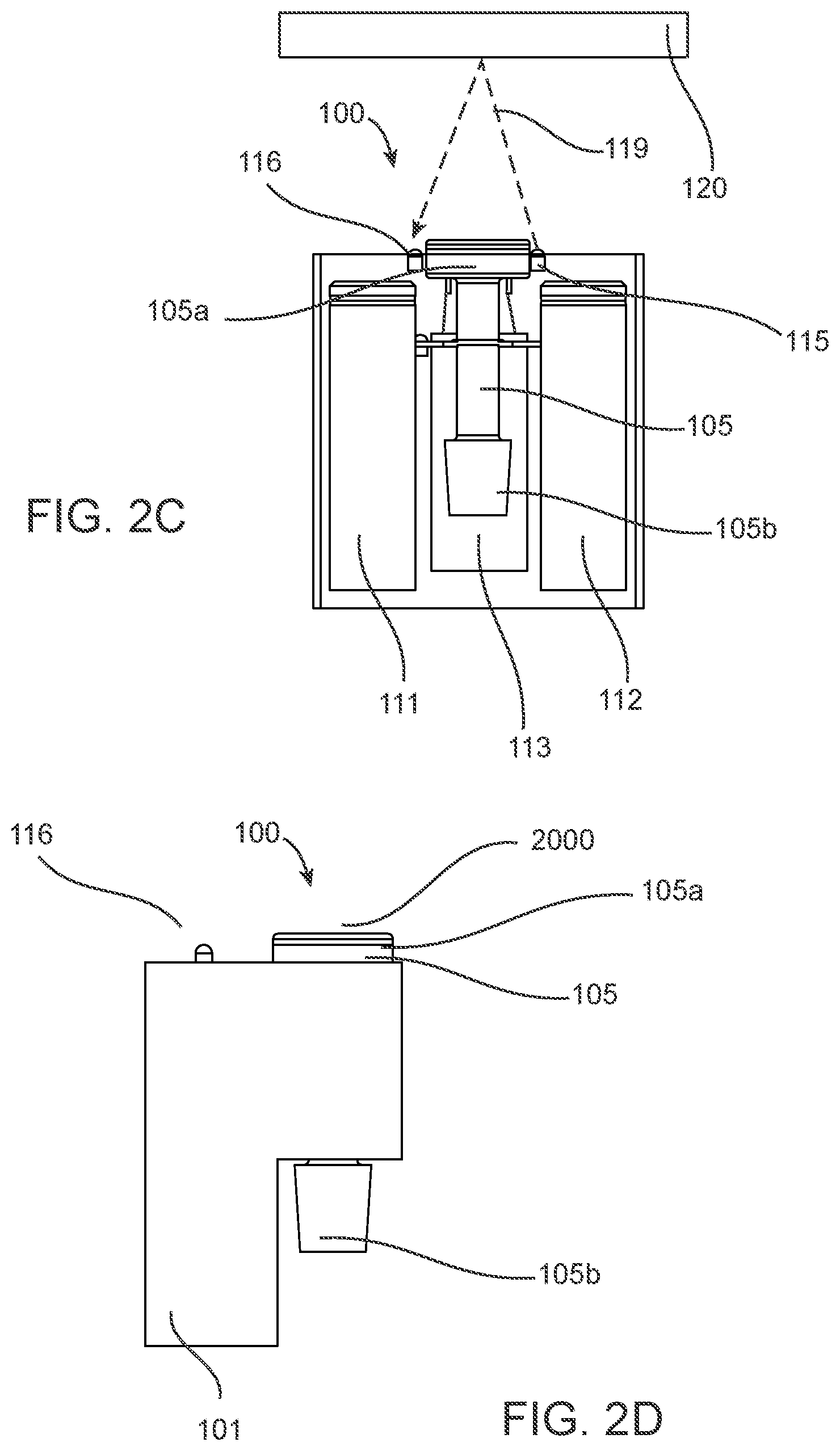
[0022] FIG. 2C illustrates a device for vaporization of concentrated phyto material extracts in accordance with the first embodiment of the invention from an opened front view;
[0023] FIG. 2D illustrates a device for vaporization of concentrated phyto material extracts in accordance with the first embodiment of the invention from a side view;
[0024] FIG. 3A illustrates a device for vaporization of concentrated phyto material extracts in accordance with a second embodiment of the invention and attached to a waterpipe;
[0025] FIG. 3B illustrates a device for vaporization of concentrated phyto material extracts in accordance with the second embodiment of the invention and showing an adjustable clamping mechanism;
[0026] FIG. 3C illustrates a device for vaporization of concentrated phyto material extracts in accordance with the second embodiment of the invention and showing a lead screw for adjusting of the adjustable clamping mechanism;
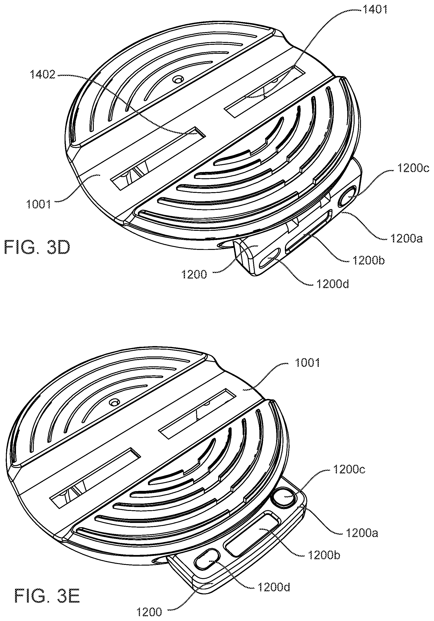
[0027] FIG. 3D illustrates a device for vaporization of concentrated phyto material extracts in accordance with the second embodiment of the invention and showing a control panel in a first position;
[0028] FIG. 3E illustrates a device for vaporization of concentrated phyto material extracts in accordance with the second embodiment of the invention and showing a control panel in a second position;
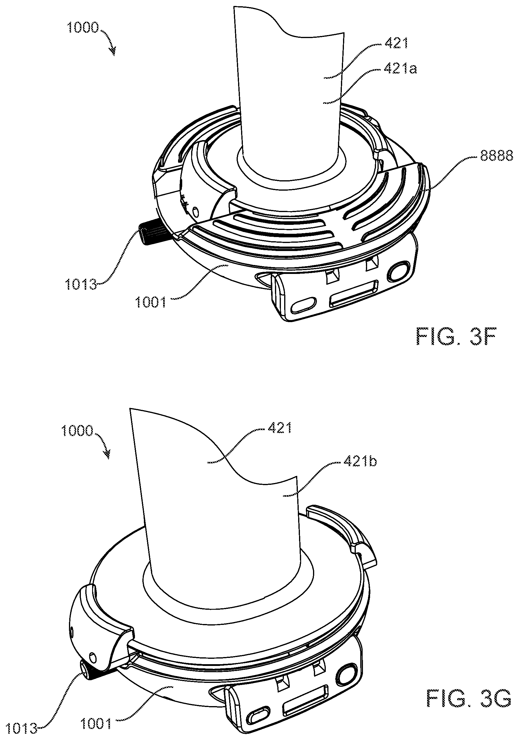
[0029] FIG. 3F illustrates a device for vaporization of concentrated phyto material extracts in accordance with the second embodiment of the invention and showing the adjustable clamping mechanism being frictionally engaged to a first diameter base waterpipe;
[0030] FIG. 3G illustrates a device for vaporization of concentrated phyto material extracts in accordance with the second embodiment of the invention and showing the adjustable clamping mechanism being frictionally engaged to a second diameter base waterpipe;
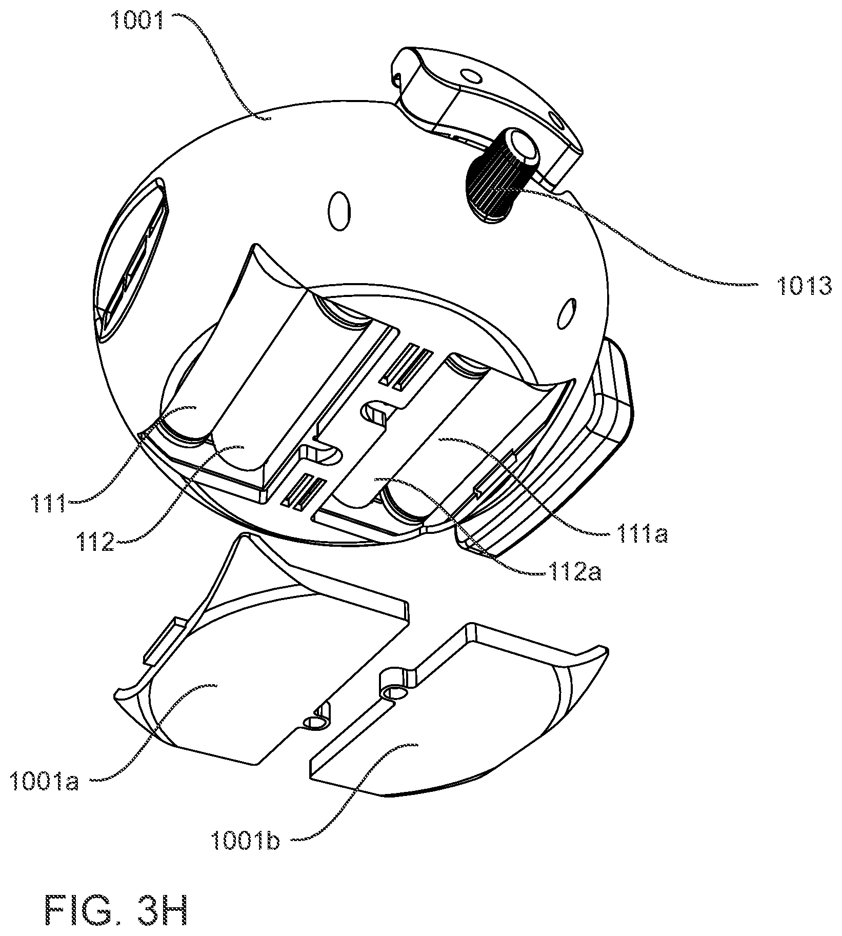
[0031] FIG. 3H illustrates a device for vaporization of concentrated phyto material extracts in accordance with the second embodiment of the invention and showing a plurality of batteries contained therein;
[0032] FIG. 3I illustrates a device for vaporization of concentrated phyto material extracts in accordance with the second embodiment of the invention and showing various input and output ports; and,
[0033] FIG. 3J a device for vaporization of concentrated phyto material extracts in accordance with the second embodiment of the invention having a first magnet and a second magnet as part of the a second coupling port.
DETAILED DESCRIPTION OF EMBODIMENTS OF THE INVENTION
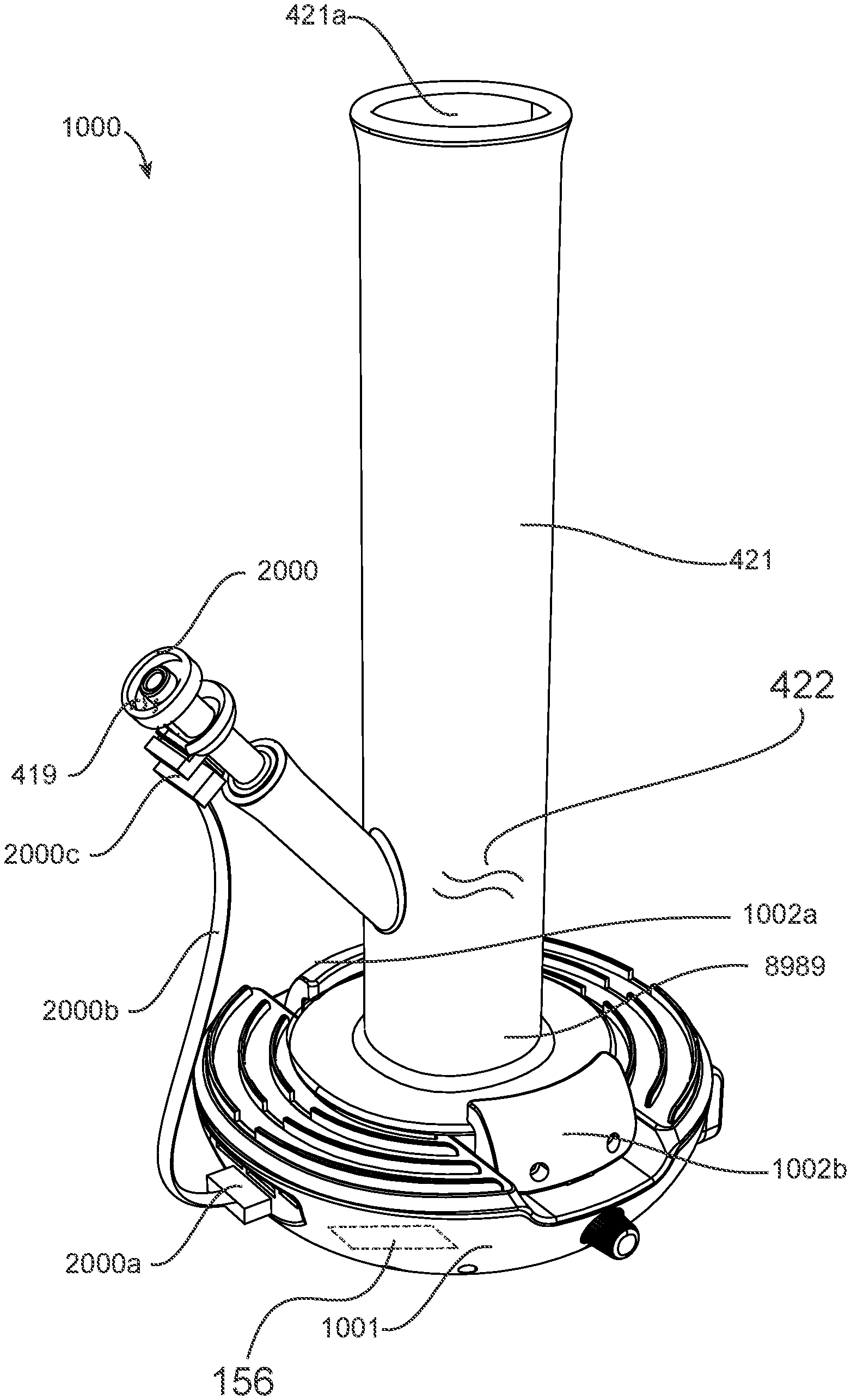
[0034] FIG. 2A illustrates a device for vaporization of concentrated phyto material extracts 100 (DVCPM) in accordance with a first embodiment of the invention. The DVCPM 100 is for attaching to a waterpipe 421 having an input port 421b and an inhalation aperture 421a with a waterpipe fluid pathway 8989 formed therebetween. FIG. 3A illustrates a device for vaporization of concentrated phyto material extracts 1000 (DVCPM) in accordance with a second embodiment of the invention. The DVCPM 1000 is for attaching to a waterpipe 421 having an input port 421b and an inhalation aperture 421a with the waterpipe fluid pathway 8989 formed therebetween.
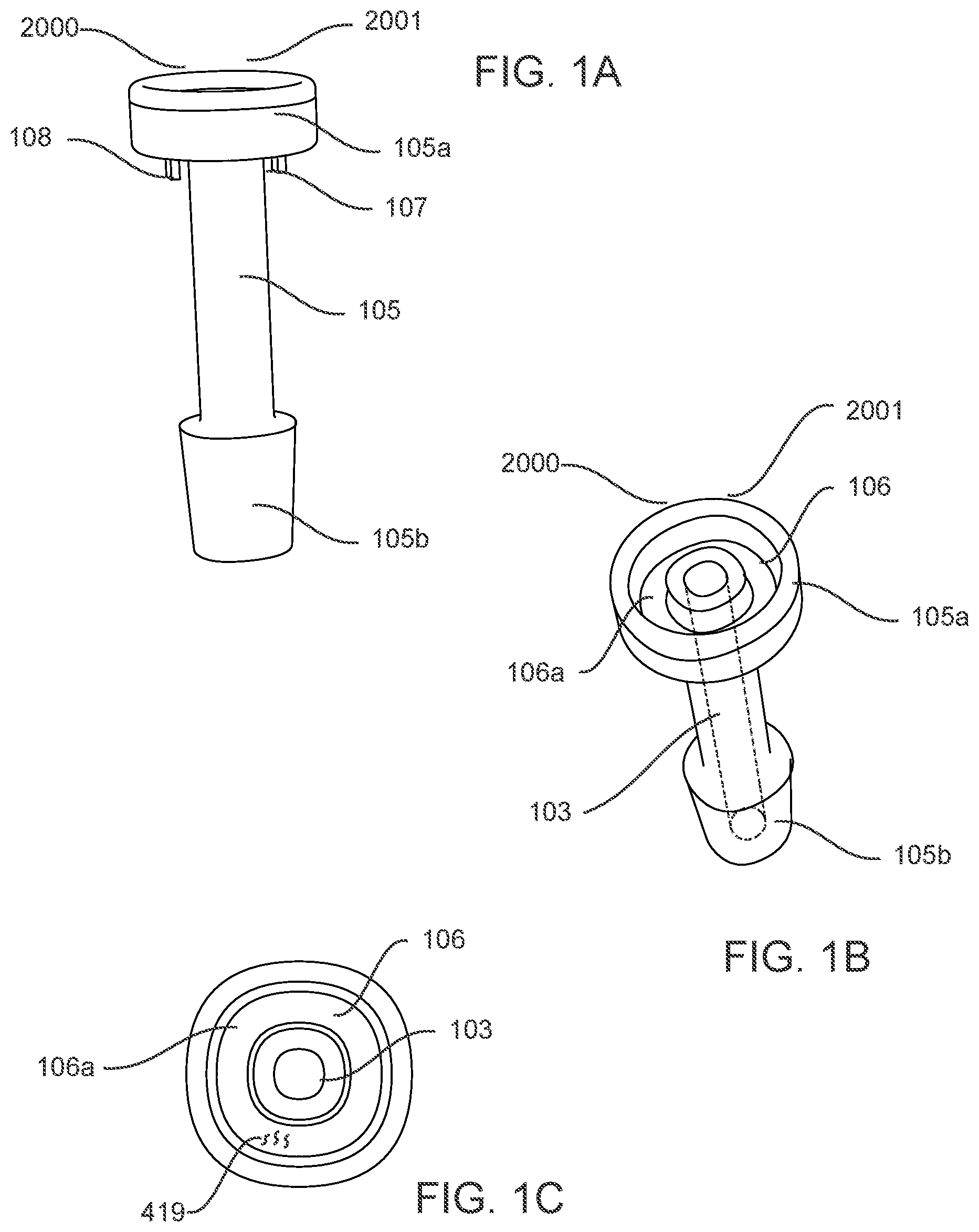
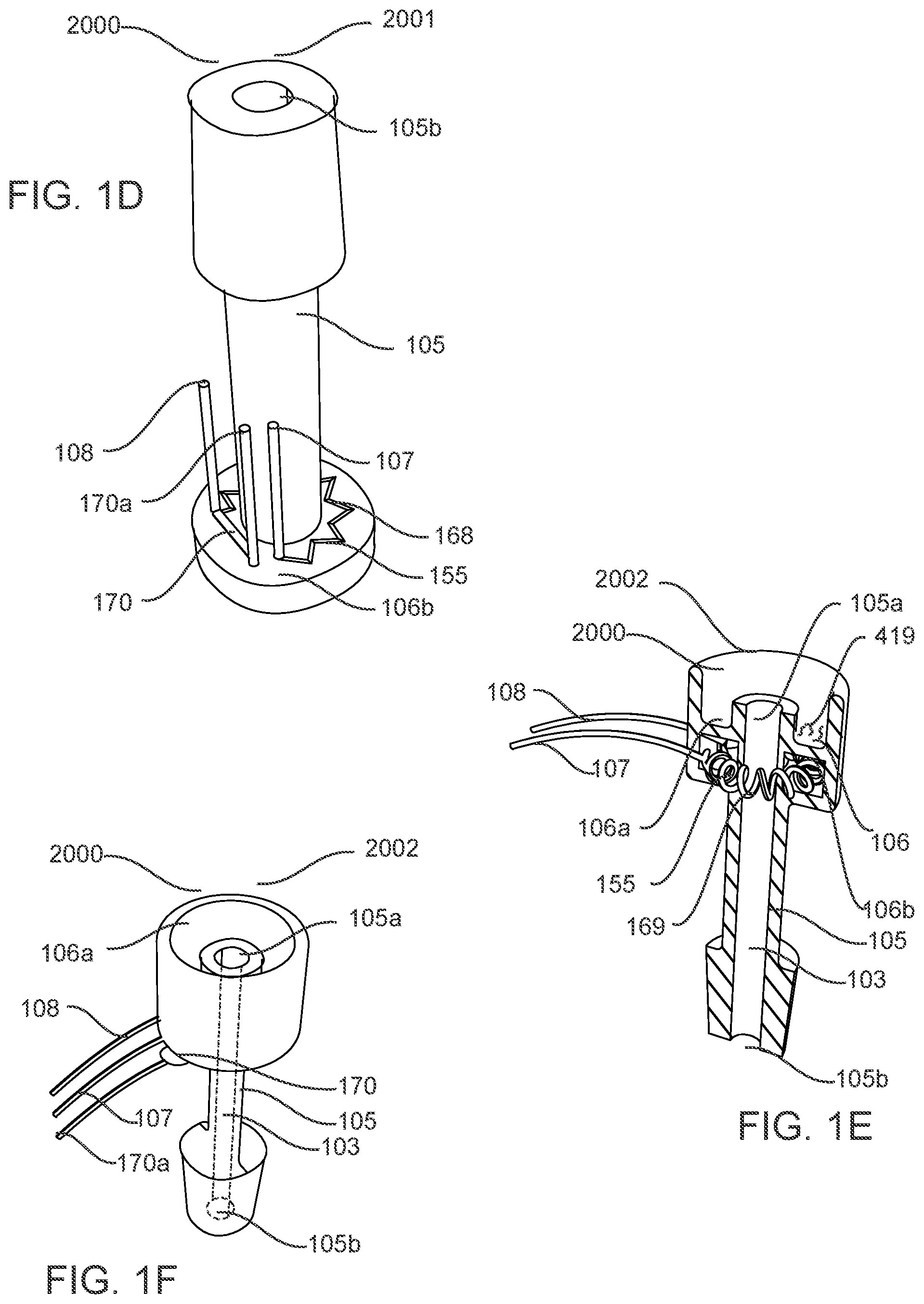
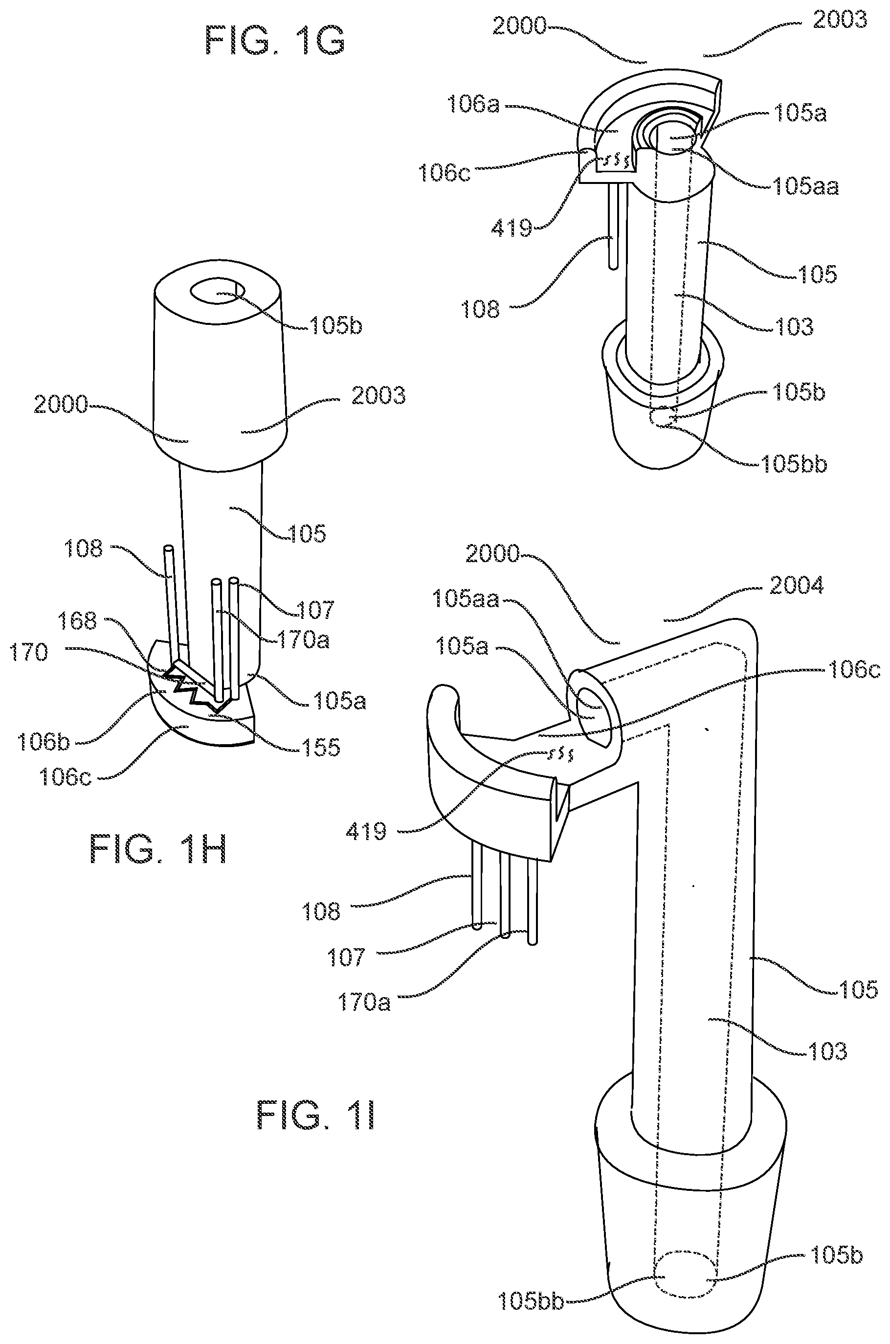
[0035] Referring to FIGS. 1A, 1B, 1C, 1D a vaporization element 2000 is shown in the form of a first vaporization element 2001. FIGS. 1E and 1F illustrate a vaporization element 2000 in the form of a second vaporization element 2002 and FIGS. 1G and 1H illustrates a vaporization element 2000 in the form of a third vaporization element 2003. FIG. 1I illustrates a vaporization element 2000 in the form of a fourth vaporization element 2004 that is a variation of the third vaporization element 2003. Throughout the detailed description, the vaporization element 2000 is for use in both of the first and second embodiments of the invention, DVCPM 100 and DVCPM 1000, respectively.
[0036] Referring to FIG. 1A, the vaporization element 2000, in the form of a first vaporization element 2001,is shown in perspective view and is formed from an elongated hollow member 105 that is made from a low thermal conductivity material, such as ceramic, and having a first end 105a and a second end 105b opposite the first end 105a, a fluid pathway 103 (as seen in FIG. 1B) propagates through the elongated hollow member 105 from the first end 105a to the second end 105b thereof. The second end 105b is for coupling with the waterpipe input port 421b, as shown in FIGS. 2A and 3A.
[0037] The vaporization element 2000 has an annular heating element 106 having a first side 106a and a second side 106b (FIG. 1D) opposite the first side 106a, the annular heating element 106 is thermally coupled with the elongated hollow member 105 proximate the first end 105a having the first side 106a facing the first end 105a with the fluid pathway 103 propagating through a center thereof (as seen in FIG. 1B), the annular heating element 106 comprises a first electrical contact 107 and a second electrical contact 108 proximate the second side 106b. The annular heating element 106 secured to the elongated hollow member 105 for allowing thermal expansion thereof along a radial axis perpendicular to the fluid pathway 103. Without properly securing the annular heating element 106 to the elongated hollow member 105 it is easy to crack the annular heating element 106 due to expansion forces of the elongated hollow member 105 and as such a unitary construction of the annular heating element 106 is preferable.
[0038] Referring to FIG. 1D, the annular heating element 106 comprising a resistive heater 155 disposed between the first and second electrical contacts, 107 and 108, and proximate the second side 106b. The annular heating element 106 comprises ceramic material where the resistive heater 155 comprises a metallic planar heater 168 disposed on the second side 106b between the first and second electrical contacts 107 108 for receiving of electrical energy from the electrical power source 156, wherein the thermal coupling between the annular heating element and the elongated hollow member 105 comprises silica material. Silica is also known in the art as ceramic glaze, so the coupling between the annular heating element 106 and the elongated hollow member 105 is by means of a ceramic glaze.
[0039] The electrical power source 156 is electrically coupled with the first and second electrical contacts 107 108 for providing of electrical power to the resistive heater 155 for heating of the resistive heater 155 for imparting thermal energy to the annular heating element 106.
[0040] As is evident from FIG. 1D, the vaporization element 2000 comprises a temperature sensor 170 thermally coupled with at least one of the elongated hollow member 105 and the annular heating element 106 proximate the second side 106b of the annular heating element 106, the temperature sensor 170 has a temperature signal output port 170a for providing a temperature signal in dependence upon the imparting of thermal energy to the annular heating element 106. Typically the temperature signal is based on a resistance of the temperature sensor 170 and the resistance varies inversely with respect to the temperature being sensed by the the temperature sensor 170.
[0041] Referring to FIG. 2A, the DVCPM 100 in accordance with the first embodiment of the invention is shown attached to a waterpipe 421 having an inhalation aperture 421a and an input port 421b. The vaporization element 2000, for example the first vaporization element 2001, but it is not limited to the first vaporization element 2001, the second vaporization element 2002 or the third vaporization element 2003 or the fourth vaporization element 2004, any of the vaporization elements 2000 are useable with the DVCPM 100.
[0042] In this embodiment the vaporization element 2000 is disposed within the first housing 101 and the first housing 101 frictionally engages the elongated hollow member 105 where the second end 105b of the elongated hollow member 105 couples with the waterpipe input port 421b. An electrical power source 156 (disposed within the first housing 101 and not visible from an outside thereof, but visible in FIG. 2C as the first and second batteries 111, 112) is provided and coupled with a first control circuit 113 electrically coupled with the electrical power source 156 (FIG. 2C) and the first and second electrical contacts 107 108 and the temperature signal output port 170a. The first control circuit 113 for processing of the temperature signal and for controllably providing of the electrical power to the resistive heater 155 for reaching the predetermined temperature of the annular heating element 106 second side 106b.
[0043] During heating of the resistive heater 155, a portion of the thermal energy is transferred to the annular heating element 106 first side 106a and another portion, other than the first portion, is transferred to the elongated hollow member 105 proximate the first end 105a, upon the annular heating element 106 second side 106b reaching a predetermined temperature the concentrated phyto material extract 419 is applied to the annular heating element 106 first side 106a (FIG. 1C) and becomes vaporized and upon inhalation from the inhalation aperture 421a this vapor 422 is mixed with ambient air 555 (FIG. 2A) and flows through the fluid pathway 103 from the first end 105a where it receives thermal energy proximate the coupling between the annular heating element 106 and the elongated hollow member 105 and loses thermal energy to the elongated hollow member 105 proximate the second end 105b as it propagates through the input port 421b of the waterpipe 421 and through to the inhalation aperture 421a.
[0044] Referring to FIGS. 1E and 1F, the vaporization element 2000, in the form of the second vaporization element 2002, is shown in perspective view and cutaway view, respectively, and is formed from an elongated hollow member 105 that is made from a low thermal conductivity material, such as glass or quartz, and having a first end 105a and a second end 105b opposite the first end 105a, a fluid pathway 103 (as seen in FIG. 1F) propagates through the elongated hollow member 105 from the first end 105a to the second end 105b thereof. The second end 105b is for coupling with the waterpipe input port 421b, as shown in FIGS. 2A and 3A.
[0045] The vaporization element 2000 has an annular heating element 106 having a first side 106a and a second side 106b opposite the first side 106a, the annular heating element 106 is thermally coupled with the elongated hollow member 105 proximate the first end 105a having the first side 106a facing the first end 105a with the fluid pathway 103 propagating through a center thereof (as seen in FIG. 1F), the annular heating element 106 comprising a first electrical contact 107 and a second electrical contact 108 proximate the second side 106b, the annular heating element 106 secured to the elongated hollow member 105 for allowing thermal expansion thereof along a radial axis perpendicular to the fluid pathway 103.
[0046] Referring to FIG. 1E, a cutaway view of the vaporization element 2000, in the form of the second vaporization element 2002, is shown. The annular heating element 106 comprising a resistive heater 155 disposed between the first and second electrical contacts, 107 and 108, and proximate the second side 106b. The resistive heater 155 comprises a resistance wire 169 disposed proximate the second side 106b between the first and second electrical contacts 107 108 for receiving of electrical energy from the electrical power source 156, wherein the thermal coupling between the annular heating element and the elongated hollow member 105 comprises glass or quartz.
[0047] The electrical power source 156 is electrically coupled with the first and second electrical contacts 107, 108 for providing of electrical power to the resistive heater 155 for heating of the resistive heater 155 for imparting thermal energy to the annular heating element 106.
[0048] Referring to FIG. 2A for example, when the second vaporization element 2002 is utilized and during heating of the resistive heater 155, a portion of the thermal energy is transferred to the annular heating element 106 first side 106a and another portion, other than the first portion, is transferred to the elongated hollow member 105 proximate the first end 105a, upon the annular heating element 106 second side 106b reaching the predetermined temperature the concentrated phyto material extract 419 is applied to the annular heating element 106 first side 106a (FIG. 1E) and becomes vaporized and upon inhalation from the inhalation aperture 421a this vapor 422 is mixed with ambient air 555 and flows through the fluid pathway 103 from the first end 105a where it receives thermal energy proximate the coupling between the annular heating element 106 and the elongated hollow member 105 and loses thermal energy to the elongated hollow member 105 proximate the second end 105b as it propagates through the input port 421b of the waterpipe 421 and through to the inhalation aperture 421a.
[0049] Referring to FIG. 1F, the vaporization element 2000 comprises a temperature sensor 170 thermally coupled with at least one of the elongated hollow member 105 and the annular heating element 106 proximate the second side 106b of the annular heating element 106, the temperature sensor 170 has a temperature signal output port 170a for providing a temperature signal in dependence upon the imparting of thermal energy to the annular heating element 106. In some cases uses a glass or quartz vaporization element 2000 is preferable because a user can see the resistance wire 169 heating up and it provides a glow as the predetermined temperature is reached.
[0050] Referring to FIGS. 1G and 1H, the vaporization element 2000 is shown in the form of the third vaporization element 2003. The vaporization element 2000 in the form of the third vaporization element 2003 is formed from an elongated hollow member 105 that is made from a low thermal conductivity material, such as ceramic, but can also be made from glass or quartz, and having a first end 105a and a second end 105b opposite the first end 105a, the fluid pathway 103 (as seen in FIG. 1G) propagates through the elongated hollow member 105 from the first end 105a to the second end 105b thereof. The second end 105b is for coupling with the waterpipe input port 421b, as shown in FIGS. 2A and 3A.
[0051] The vaporization element 2000 has a annular heating element 106 that is a partial annular heating element 106c that does not comprise a full three hundred and sixty degrees arc about the fluid pathway 103 when thermally coupled about the elongated hollow member 105 and has a portion thereof removed, wherein it comprise about a ninety degrees arc about the fluid pathway when disposed about the elongated hollow member 105.
[0052] The partial annular heating element 106c is radially disposed with respect to the elongated hollow member 105. As shown in FIG. 1G, the elongated hollow member 105 comprises a first aperture 105aa proximate the first end thereof 105a and a second aperture 105bb proximate the second end thereof 105b and the fluid pathway 103 formed between the first and second apertures, 105aa and 105bb, wherein the first and second apertures are axially disposed and comprises the resistive heater 155. Preferably the partial annular heating element 106c is disposed proximate the first end 105a of the elongated hollow member 105.
[0053] The partial annular heating element 106c has a first side 106a and a second side 106b opposite the first side 106a, partial annular heating element 106c is thermally coupled with the elongated hollow member 105 proximate the first end 105a having the first side 106a facing the first end 105a with the fluid pathway 103 propagating through a center thereof (as seen in FIG. 1G), the partial annular heating element 106c comprising a first electrical contact 107 and a second electrical contact 108 proximate the second side 106b, the partial annular heating element 106c secured to the elongated hollow member 105 for allowing thermal expansion thereof along a radial axis that is perpendicular to the fluid pathway 103.
[0054] Referring to FIG. 1H, the partial annular heating element 106c comprising a resistive heater 155 disposed between the first and second electrical contacts, 107 and 108, and proximate the second side 106b. The partial annular heating element 106c comprises ceramic material where the resistive heater 155 comprises a metallic planar heater 168 disposed on the second side 106b between the first and second electrical contacts 107 108 for receiving of electrical energy from the electrical power source 156, wherein the thermal coupling between the partial annular heating element 106c and the elongated hollow member 105 comprises silica material.
[0055] The electrical power source 156 is electrically coupled with the first and second electrical contacts 107 108 for providing of electrical power to the resistive heater 155 for heating of the resistive heater 155 for imparting thermal energy to the partial annular heating element 106c.
[0056] Referring to FIG. 2A, when the vaporization element 2000 in the form of the third vaporization element 2003 is coupled with the waterpipe 421, during heating of the resistive heater 155, a portion of the thermal energy is transferred to the partial annular heating element 106c first side 106a and another portion, other than the first portion, is transferred to the elongated hollow member 105 proximate the first end 105a, upon the partial annular heating element 106c second side 106b reaching the predetermined temperature the concentrated phyto material extract 419 is applied to the partial annular heating element 106c first side 106a (FIG. 1G) and becomes vaporized and upon inhalation from the inhalation aperture 421a this vapor 422 is mixed with ambient air 555 and flows through the fluid pathway 103 from the first end 105a where it receives thermal energy proximate the coupling between the partial annular heating element 106c and the elongated hollow member 105 and loses thermal energy to the elongated hollow member 105 proximate the second end 105b as it propagates through the input port 421b of the waterpipe 421 and through to the inhalation aperture 421a.
[0057] Referring to FIG. 1H, the vaporization element 2000 comprises a temperature sensor 170 thermally coupled with at least one of the elongated hollow member 105 and the partial annular heating element 106c proximate the second side 106b of the partial annular heating element 106c, the temperature sensor 170 has a temperature signal output port 170a for providing a temperature signal in dependence upon the imparting of thermal energy to the partial annular heating element 106c.
[0058] FIG. 1I illustrates a variation of the third vaporization element 2003 having the partial annular heating element 2003 in the form of a fourth vaporization element 2004, whereby the resistive heater 155 (not visible in this FIG. 1I) is disposed between the first and second electrical contacts, 107 and 108, is at a distance, for example 20 mm, from an axial center of the first end 105a of the elongated hollow member 105. Whereby in comparison, for the third vaporization element 2003 the resistive heater 155 is approximately 6mm away from the axial center of the first end 105a of the elongated hollow member 105.
[0059] Furthermore, the fluid pathway 103 is curved between the first end 105a and the second end 105b. Such a variation may be preferable so that thermal transfer from the fourth vaporization element 2004 to the elongated hollow member 105 (e.g. a hollow ceramic member) is reduced as well the fourth vaporization element 2004 provides for a lower thermal inertia than the first vaporization element 2001.
[0060] The elongated hollow member 105 comprises a first aperture 105aa proximate the first end thereof 105a and a second aperture 105bb proximate the second end thereof 105b and the fluid pathway 103 formed between the first and second apertures, wherein the first and second apertures 105aa and 105bb are other than axially disposed and preferably central axes of the first and second apertures 105aa and 105bb are perpendicular to each other.
[0061] In this fourth vaporization element 2004 the resistive heater 155 is radially disposed away from the elongated hollow member 105, which therefore results in a bend in the fluid pathway 103. Using the fourth vaporization element 2004 is sometimes preferable as it allows for an elongated path length for the fluid pathway 103 and as such improved cooling for the vapor 422 as it propagates through the fluid pathway 103. If the fourth vaporization element 2004 uses quartz material then the resistive heater 155 is envisaged comprising a pancake ceramic heater or a resistance wire 169. If the fourth vaporization element 2004 uses a ceramic material then the resistive heater 155 is envisaged comprising a metallic planar heater 168 that is sintered onto the ceramic.
[0062] Referring to FIG. 2A and in conjunction with FIGS. 2A, 2B and 2D a first infrared transmitter 115 is envisaged for protruding past the first housing 101 proximate the first end 105a of the vaporization element 2000. FIG. 2B illustrates a top view and FIG. 2C illustrates an internal front view and FIG. 2D illustrates a closed side view.
[0063] A first infrared receiver 116 is provided for protruding past the first housing 101 proximate the first end 105a of the vaporization element 2000, the first infrared transmitter 115 and the first infrared receiver 116 are electrically coupled with the first control circuit 113, the first infrared transmitter 115 for sending out a first infrared signal 119 for being reflected from an infrared signal reflective member 120 for being received by the first infrared receiver 116 for enabling the heating of the annular heating element 106 (e.g. an annular ceramic heating element) and for other than being received by the first infrared receiver 116 when the infrared signal reflective member 120 is other than present, upon heating of the annular heating element 106, the concentrated phyto material extract 419 is heated to the predetermined temperature and becomes vaporized and this vapor 422 and is mixed with ambient air 555 and flows through the fluid pathway 103, as illustrated in FIG. 2A.
[0064] Preferably the infrared signal reflective member 120 is in the form of a hand, whereby when the hand of a user is waived over the top of the DVCPM 100, this activates the first control circuit 113 for heating of the vaporization element 2000. Referring to FIG. 2C, a first battery 111 and a second battery 112 are shown as part of the electrical power source 156. Any of the vaporization elements 2000 in the form of the first through fourth, 2001 through 2004, are envisaged to work with the first infrared transmitter 115 and the first infrared receiver 116.
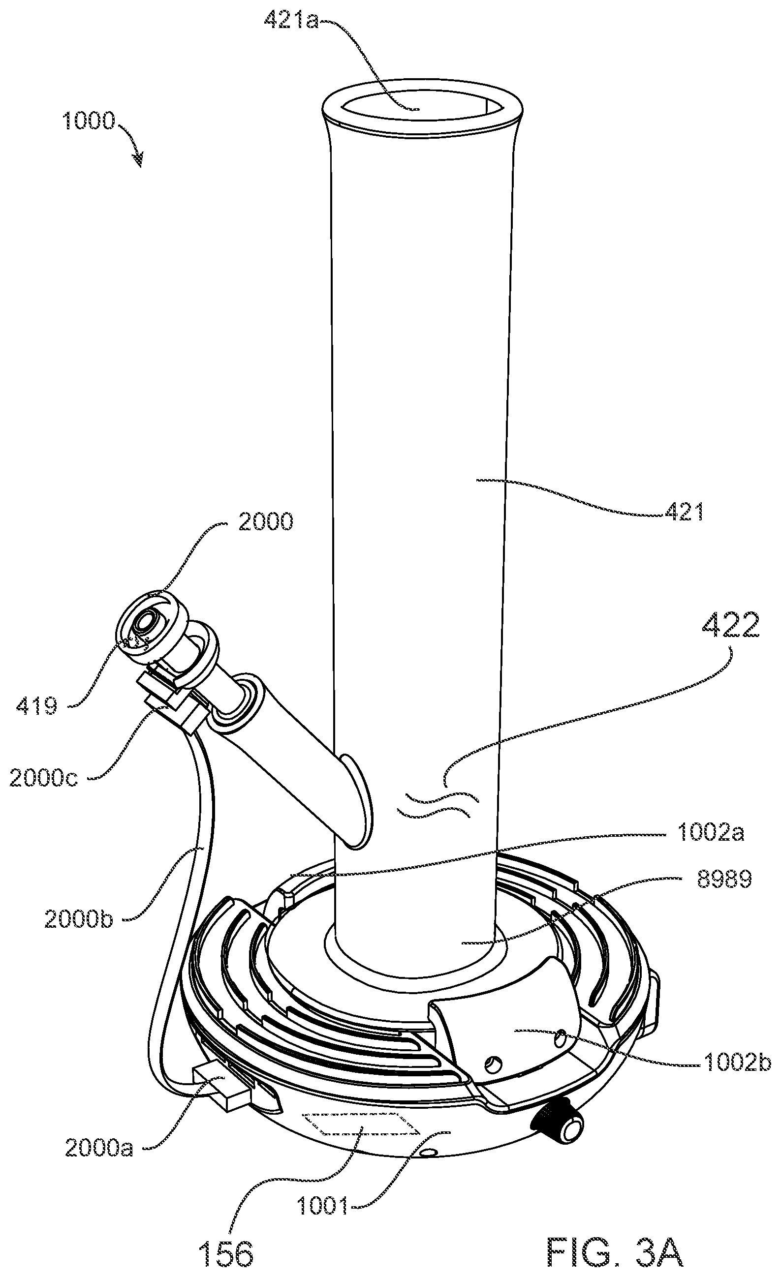
[0065] FIG. 3A illustrates a device for vaporization of concentrated phyto material extracts 1000 (DVCPM) in accordance with a second embodiment of the invention. The DVCPM 1000 is for attaching to a waterpipe 421 having an input port 421b and an inhalation aperture 421a with a waterpipe fluid pathway 8989 formed therebetween. The DVCPM 1000 includes the vaporization element 2000 having the second end 105b coupled with the input port 421b. The waterpipe 421 has a first housing 1001 for preferably having the an electrical power source 156 contained therein, the first housing 1001 comprising an adjustable clamping mechanism 1002, as is shown in FIG. 3B, for frictionally engaging of the waterpipe 421.
[0066] FIG. 3A furthermore illustrates a vaporization element first coupling port 2000a electrically coupled with the first control circuit 113 (FIG. 3C) and vaporization element second coupling port 2000c electrically coupled with the vaporization element 2000 first and second electrical contacts 107 108 and the temperature signal output port 170a.
[0067] A vaporization element connector cable 2000b is electrically coupled between the vaporization element first coupling port 2000a and the vaporization element second coupling port 2000c, the vaporization element connector cable 2000b is for electrically coupling of the vaporization element 2000 with the first control circuit 113 (FIG. 3C).
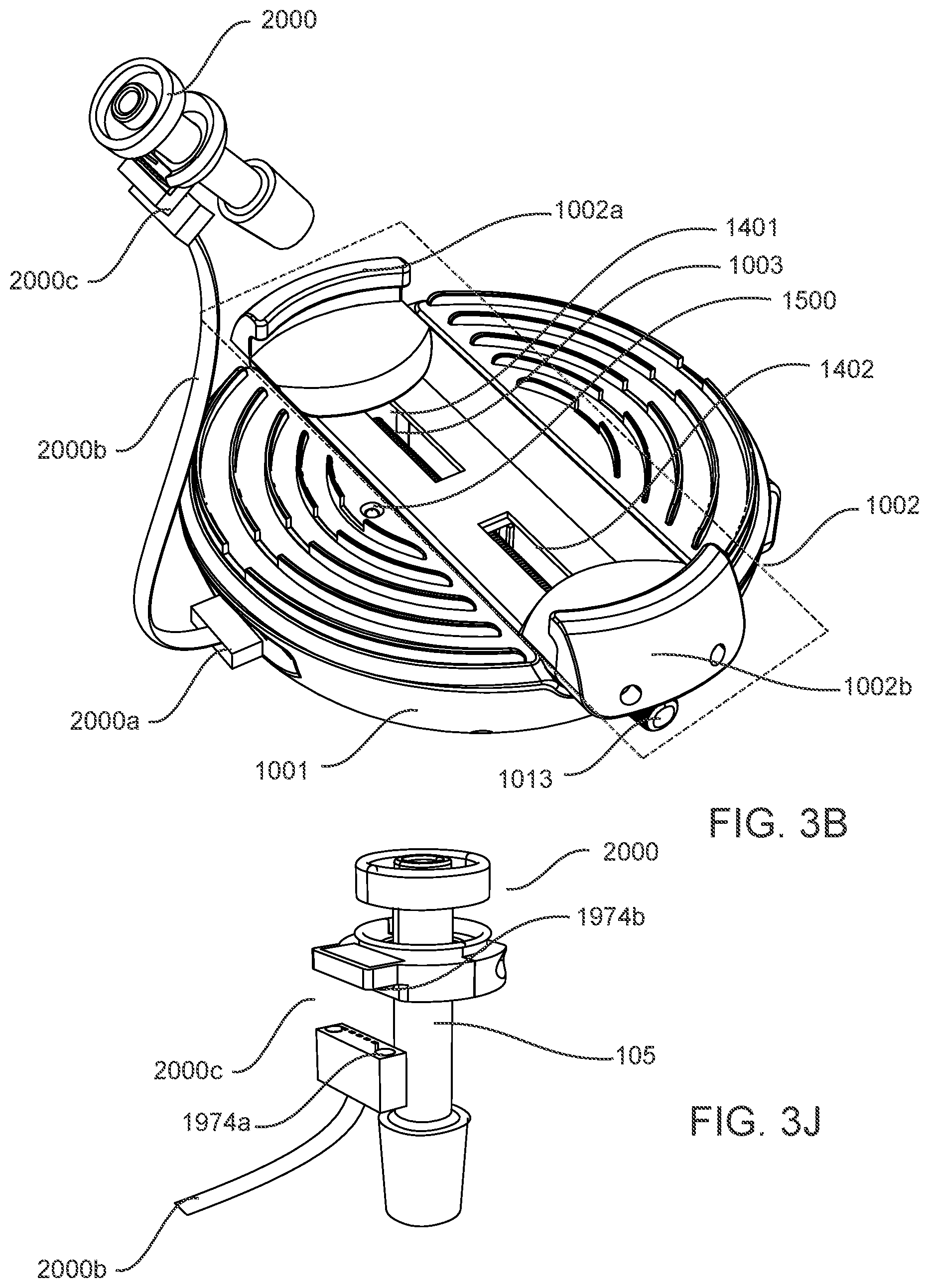
[0068] Preferably the vaporization element connector cable 2000b is magnetically and electrically coupled with the vaporization element whereby the second coupling port 2000c comprises a magnetic coupling. FIG. 3j illustrates a first magnet 1974a and a second magnet 1974b whereby the second coupling port 2000c is electrically and mechanically held together using the first and second magnets 1974a and 1974b. However a standard pin connector is also envisaged as would be obvious to one skilled in the art.
[0069] Referring to FIG. 3B, the adjustable clamping mechanism 1002 comprises a first jaw 1002a and a second jaw 1002b disposed opposite the first jaw 1002a, the first and second jaws are mechanically coupled to a lead screw 1003, for upon rotating of the lead screw 1003 in a clockwise direction for increasing a frictional engagement of the waterpipe 421 and for upon rotating of the lead screw in a counter clockwise direction for decreasing a frictional engagement of the waterpipe 421, wherein a spacing between the first jaw 1002a and the second jaw 1002b varies between 6 cm and 15 cm, the first and second jaws 1002a and 1002b for respectively sliding within a first track 1401 and a second track 1402. A thumb screw 1013 is provided and frictionally coupled with the lead screw 1003 and at least partially protruding past the first housing 1001 for being turned to adjust the lead screw 1003.
[0070] This allows the end user the possibility to adjust the adjustable clamping mechanism 1002 to accommodate various water pipe bases. FIG. 3F illustrates the waterpipe 421 as a first diameter base waterpipe 421a being frictionally engaged by the adjustable clamping mechanism 1002 when the first and second jaws 1002a and 1002b are in a first position and FIG. 3G illustrates the waterpipe 421 as a second diameter base waterpipe 421b being frictionally engaged by the adjustable clamping mechanism 1002 when the first and second jaws 1002a and 1002b are in a second position. Because the second diameter base waterpipe 421b is of a larger diameter than the first diameter base waterpipe 421a, a spacing between the first and second jaws is larger in the second position than the first position.
[0071] Additionally shown in FIG. 3F is a plurality of deformable ribs 8888 used for assisting in frictionally contacting the waterpipe 421 when its frictionally engaged by the adjustable clamping mechanism 1002.
[0072] A three colored LED 1500 is also provided and protrudes past the first housing 1001 and is optically aimed at the waterpipe 421. The LED 1500 electrically coupled with the first control circuit 113, the LED 1500 for directing light towards the waterpipe 421 and for changing color in dependence upon the temperature signal. For example the LED 1500 has a blue color when a temperature of the resistive heater 155 is around 200 degrees Fahrenheit and has a red color when the temperature of the resistive heater 155 is around 600 degrees Fahrenheit.
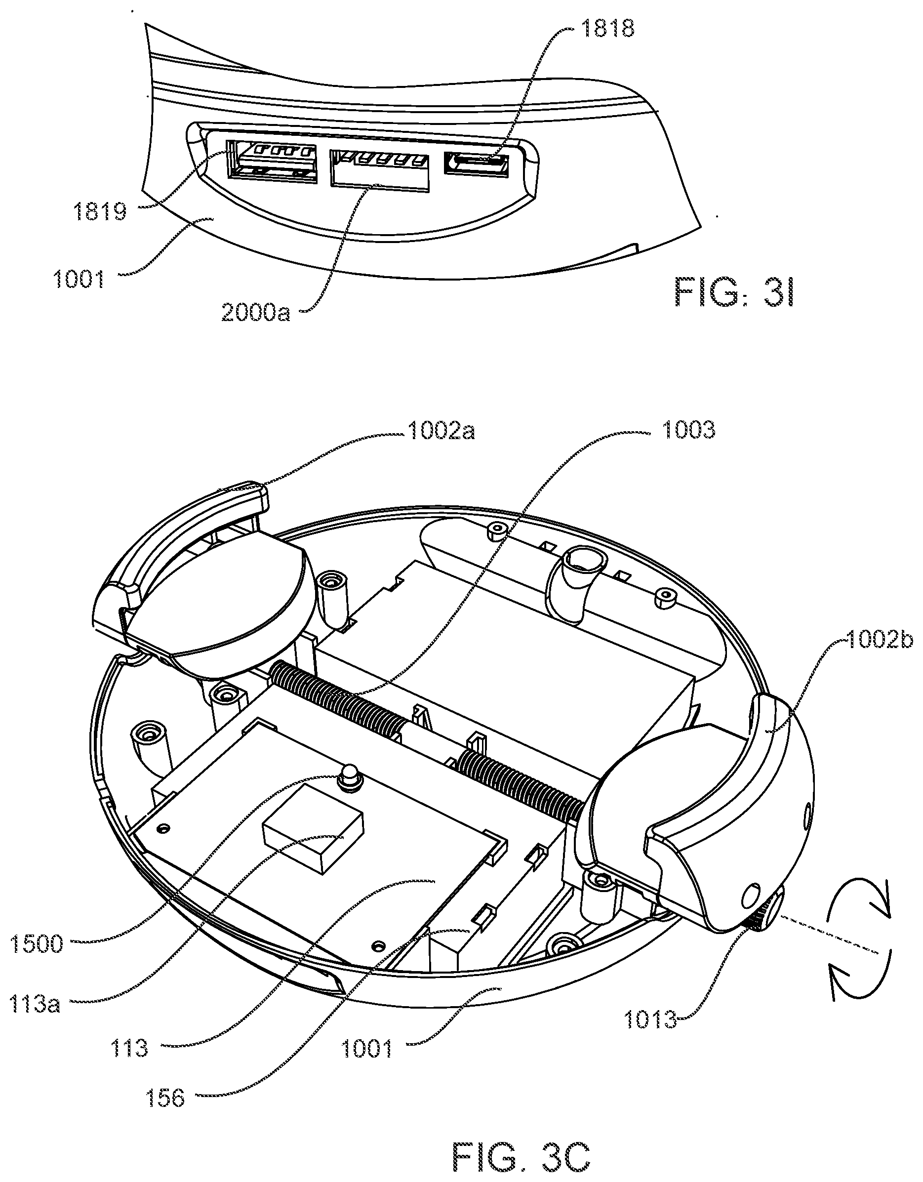
[0073] Referring to FIG. 3C, the first control circuit 113 electrically coupled with the electrical power source 156 and the first and second electrical contacts 107 108 of the vaporization element and the temperature signal output port 170a, the first control circuit 131 includes a first processor 113a for processing of the temperature signal and for controllably providing of the electrical power to the resistive heater 155 for reaching the predetermined temperature.
[0074] Referring to FIGS. 3D and 3E, a control panel 1200 is provided having a control surface 1200a, the control panel 1200 is rotationally coupled with the first housing 1001, the control panel being hinged with the first housing 1001 for operating between a first position (FIG. 3D) and a second position (FIG. 3E), wherein in the first position the control surface 1200a is approximately perpendicular to the first track 1401 and the second track 1402 and where in the second position the control surface 1200a is approximately parallel to the first track 1401 and the second track 1402.
[0075] Furthermore, the control panel 1200 comprises an OLED display screen 1200b electrically coupled with the first control circuit 113 for displaying a temperature in dependence upon the temperature control signal and an activation button 1200c electrically coupled with the first control circuit 113 for enabling operation of the first control circuit 113 and a temperature adjustment rocker button 1200d electrically coupled with the first control circuit 113 for adjusting the predetermined temperature from, for example 100 degrees Celsius to 400 degrees Celsius.
[0076] FIG. 3H illustrates the DVCPM 1000 from a bottom view of the first housing 1001 and showing a plurality of batteries 111, 112, 111a, 112a as the electrical power source 156, the plurality of batteries 111, 112, 111a, 112a electrically coupled in series and electrically coupled with the first control circuit 113, wherein the first housing 1001 comprises a first battery door 1001a and a second battery door 1001b, wherein the batteries 111 and 112 are removable through the first battery door 1001a and the batteries 111a and 112a are removable through the second battery door 1001b.
[0077] FIG. 3I illustrates the DVCPM 1000 with various input and output ports, such as a USB-C port 1818 for receiving of electrical energy from a recharger (not shown) and a USB port 1819 for providing of electricity from the electrical power source 156 to connected external devices for being recharged, such as a cellular phone. The vaporization element first coupling port 2000a is also oriented proximate the USB-C and the USB port and these ports are electrically coupled with the first control circuit 113. The DVCPM 1000 thus can also act as a portable battery bank for recharging other electrical devices and for storing electrical energy therein for portable heating of the vaporization element 2000.
[0078] Having a device for vaporization of concentrated phyto material extracts in accordance with the first and second embodiments of the invention 100 and 1000, respectively, allows for a reduction in potential harm from combustion of the phyto material extracts 419. Furthermore it allows for a portable device that overcomes the deficiencies in the prior art. Having the vaporization element 2000 manufactured from ceramic or glass or quartz allows for easy cleaning. Also because this vaporization element 2000 is manufactured from a low thermal conductivity material allows for the second end 105b thereof to be substantially cooler than the first end 105a, thus allowing the elongated hollow member 105 to provide additional cooling to the vapors 421 and ambient air 555 when propagating therethrough. Ceramic and glass materials are also easy to clean and do not typically stain when used for vaporization of phyto material extracts 419. The LED 1500 advantageously provides for an indication to the end user of the approximate temperature of the vaporization element 2000. Preferably the electrical power source 156is from internal battery power, however a wall adapter is also envisaged.
[0079] Numerous other embodiments are envisaged without departing from the spirit or scope of the invention.
* * * * *
D00000
D00001
D00002
D00003
D00004
D00005
D00006
D00007
D00008
D00009
D00010
D00011
XML
uspto.report is an independent third-party trademark research tool that is not affiliated, endorsed, or sponsored by the United States Patent and Trademark Office (USPTO) or any other governmental organization. The information provided by uspto.report is based on publicly available data at the time of writing and is intended for informational purposes only.
While we strive to provide accurate and up-to-date information, we do not guarantee the accuracy, completeness, reliability, or suitability of the information displayed on this site. The use of this site is at your own risk. Any reliance you place on such information is therefore strictly at your own risk.
All official trademark data, including owner information, should be verified by visiting the official USPTO website at www.uspto.gov. This site is not intended to replace professional legal advice and should not be used as a substitute for consulting with a legal professional who is knowledgeable about trademark law.