Adjustable Three-dimensional Image-capturing Device
CHEN; YE-QUANG ; et al.
U.S. patent application number 16/280232 was filed with the patent office on 2020-07-09 for adjustable three-dimensional image-capturing device. The applicant listed for this patent is TRIPLE WIN TECHNOLOGY(SHENZHEN) CO.LTD.. Invention is credited to CHIA-WEI CHEN, SHIN-WEN CHEN, YE-QUANG CHEN, SHENG-JIE DING, JING-WEI LI.
| Application Number | 20200221065 16/280232 |
| Document ID | / |
| Family ID | 69942653 |
| Filed Date | 2020-07-09 |


| United States Patent Application | 20200221065 |
| Kind Code | A1 |
| CHEN; YE-QUANG ; et al. | July 9, 2020 |
ADJUSTABLE THREE-DIMENSIONAL IMAGE-CAPTURING DEVICE
Abstract
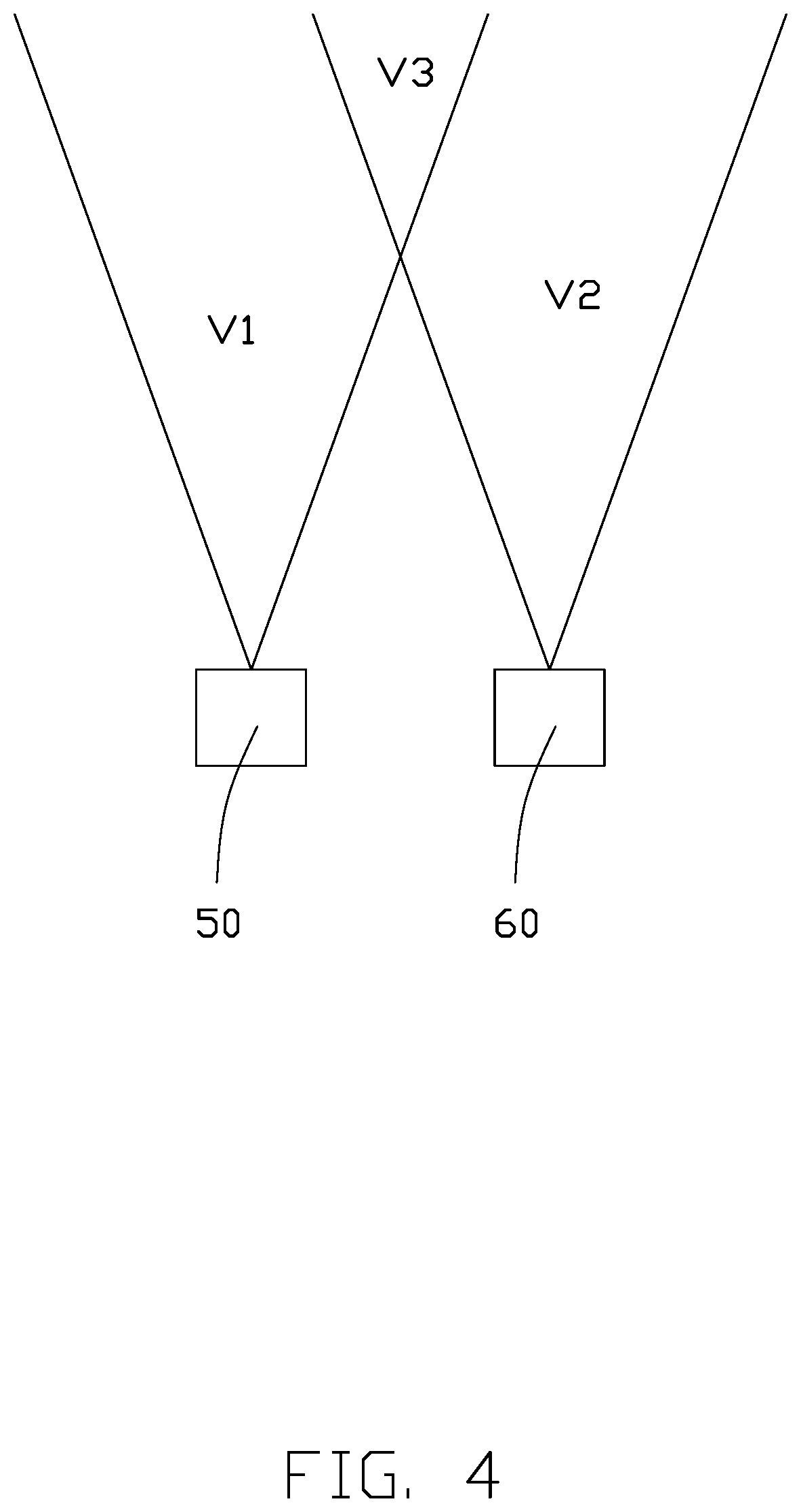
A three-dimensional image-capturing device includes a first camera, a second camera, a driving member and a sensing member. The second camera is at one side of the first camera and is capable of being moved laterally by the driving member. After depth-sensing and establishing orientations in an image, the driving member is able to drive the second camera to move relative to the first camera, to change a distance between the first camera and the second camera. Such relative movement allows a greater range of three dimensionality for face recognition and other purposes.
| Inventors: | CHEN; YE-QUANG; (New Taipei, TW) ; CHEN; SHIN-WEN; (New Taipei, TW) ; LI; JING-WEI; (Shenzhen, CN) ; CHEN; CHIA-WEI; (New Taipei, TW) ; DING; SHENG-JIE; (Shenzhen, CN) | ||||||||||
| Applicant: |
|
||||||||||
|---|---|---|---|---|---|---|---|---|---|---|---|
| Family ID: | 69942653 | ||||||||||
| Appl. No.: | 16/280232 | ||||||||||
| Filed: | February 20, 2019 |
| Current U.S. Class: | 1/1 |
| Current CPC Class: | H04N 2013/0081 20130101; H04N 13/239 20180501; H04N 2213/001 20130101; G03B 35/08 20130101; H04N 13/296 20180501 |
| International Class: | H04N 13/239 20060101 H04N013/239; G03B 35/08 20060101 G03B035/08; H04N 13/296 20060101 H04N013/296 |
Foreign Application Data
| Date | Code | Application Number |
|---|---|---|
| Jan 8, 2019 | CN | 201910017287.1 |
Claims
1. A three-dimensional image-capturing device comprising: a first camera having a first field of view; a driving member; a second camera having a second field of view, the second camera being placed at one side of the first camera and connected to the driving member; and an image processor being electrically connected to the first camera, wherein the second camera and the driving member, the driving member is adapted for driving the second camera moving at a certain distance relative to the first camera; each of the first camera and the second camera captures images of an object to be identify in an overlapping field of view of the first field of view and the second first field of view, the image processor receives and processes images taken by the first camera and the second camera to obtain 3D images of the object to be identified.
2. The three-dimensional image-capturing device of claim 1, wherein further comprises a distance sensing unit electrically connecting to the driving member, the distance sensing unit senses a distance between the object to be identify and the three dimensional image-capturing device and transfer the distance to the driving member, the driving member drive the second camera moving according to the distance.
3. The three-dimensional image-capturing device of claim 2, further comprises a pedestal and a first printed circuit board placed on the pedestal, the first printed circuit board comprising a first connector, the image processor being placed on the first printed circuit board, and the first camera being fixed and electrically connected to the first printed circuit board via the first connector.
4. The three-dimensional image-capturing device of claim 3 further comprises a second printed circuit board, wherein the second printed circuit board is a rigid-flexible circuit board and comprises a first rigid board, a flexible board portion extending from one end of the first rigid board and a second rigid board connected to the flexible board portion, the second rigid board is electrically connected to the first printed circuit board through a second connector fixed on the first printed circuit board, the second camera is electrically connected to the first rigid board.
5. The three-dimensional image-capturing device of claim 4, wherein: the driving member is mounted on the pedestal and comprises a driving body, a driving shaft connected with the driving body and a moving block connected with the driving shaft, the driving body is adapted for driving the moving block moving along the driving shaft, and the second camera is fixed on the moving block.
6. The three-dimensional image-capturing device of claim 5, wherein: the pedestal is substantially rectangular and comprises a first supporting portion and a guide rail portion at one side of the first supporting portion, the first supporting portion comprises a flat surface, the first camera is fixed on the first supporting portion.
7. The three-dimensional image-capturing device of claim 6, wherein: the moving block is placed on the guide rail portion and clamed on the guide rail portion.
8. The three-dimensional image-capturing device of claim 7, wherein: the guide rail portion comprises a substrate protruding from the pedestal and a first plate perpendicularly connected to the substrate, two ends of a width direction of the first plate are outside two ends of a width direction of the substrate, and top surface of the pedestal, the substrate and the first plate form two parallel sliding channels at opposite ends of a length direction of the substrate.
9. The three-dimensional image-capturing device of claim 8, wherein: the moving block comprises a second plate placed on the first plate and two connecting arms, the connecting arm is L-shaped, the two connecting arms vertically connected to bottom of the second plate and are clawed toward each other.
10. The three-dimensional image-capturing device of claim 9, wherein: each of the connecting arms and the second plate form a receiving channel, the receiving channel receives the first plate, and the connecting arms is configured to slide along the slide groove.
11. The three-dimensional image-capturing device of claim 10, wherein: the moving block comprises a connecting block on an outer surface of one connecting arm, the connecting block defines a through hole, an extending direction of the through hole is same as an extending direction of the slide groove.
12. The three-dimensional image-capturing device of claim 11 further comprises a housing fixed on the pedestal, the transparent cover covering the housing to seal the first camera and the second camera.
13. A three-dimensional image-capturing device comprising: a first camera; a driving member; and a second camera being placed at one side of the first camera; the second camera being connected to the driving member; wherein the driving member is adapted for driving the second camera moving relative to the first camera to change a distance between the first camera and the second camera.
14. The three-dimensional image-capturing device of claim 13, further comprises a pedestal and a first printed circuit board placed on the pedestal, the first printed circuit board comprising a first connector and the first camera is fixed and electrically connected to the first printed circuit board via the first connector.
15. The three-dimensional image-capturing device of claim 14, wherein: the pedestal is substantially rectangular and includes a first supporting portion and a guide rail portion located at one side of the first supporting portion, the first supporting portion comprises a flat surface, the first camera is fixed on the flat surface of the first supporting portion.
16. The three-dimensional image-capturing device of claim 15, wherein: the driving member is mounted on the pedestal and comprises a driving body, a driving shaft connected with the driving body and a moving block connected with the driving shaft, the driving body is able to drive the moving block moving along the driving shaft, and the second camera is fixed on the moving block.
17. The three-dimensional image-capturing device of claim 16, further comprises a second printed circuit board, wherein the second printed circuit board is a rigid-flexible circuit board and comprises a first rigid board, a flexible board portio
D00000
D00001
D00002
D00003
D00004
D00005
D00006
XML
uspto.report is an independent third-party trademark research tool that is not affiliated, endorsed, or sponsored by the United States Patent and Trademark Office (USPTO) or any other governmental organization. The information provided by uspto.report is based on publicly available data at the time of writing and is intended for informational purposes only.
While we strive to provide accurate and up-to-date information, we do not guarantee the accuracy, completeness, reliability, or suitability of the information displayed on this site. The use of this site is at your own risk. Any reliance you place on such information is therefore strictly at your own risk.
All official trademark data, including owner information, should be verified by visiting the official USPTO website at www.uspto.gov. This site is not intended to replace professional legal advice and should not be used as a substitute for consulting with a legal professional who is knowledgeable about trademark law.