Systems And Methods For A Dual Axis Resonant Scanning Mirror
HALL; David ; et al.
U.S. patent application number 16/241849 was filed with the patent office on 2020-07-09 for systems and methods for a dual axis resonant scanning mirror. This patent application is currently assigned to Velodyne LiDAR, Inc.. The applicant listed for this patent is Velodyne LiDAR, Inc.. Invention is credited to Anand GOPALAN, David HALL, Matthew REKOW, Garrett ROGREN.
| Application Number | 20200218062 16/241849 |
| Document ID | / |
| Family ID | 71403745 |
| Filed Date | 2020-07-09 |


View All Diagrams
| United States Patent Application | 20200218062 |
| Kind Code | A1 |
| HALL; David ; et al. | July 9, 2020 |
SYSTEMS AND METHODS FOR A DUAL AXIS RESONANT SCANNING MIRROR
Abstract
Described herein are systems and methods that implement a dual axis resonant scanning mirror to support a sensor system such as a LIDAR system. The scanning mirror may comprise: 1) a small dual axis mirror, in which each axis is moving by similar electromagnetic mechanisms can generate crosstalk between each of these electromagnetic mechanisms causing perturbations in the motion; 2) a primary axis that may need to be driven independently of the motion of a secondary axis and vice versa; 3) an optical position sensor; 4) a scanning mirror assembly that may be mounted to a scanner base via the secondary axis. The scanning mirror assembly may comprise resonant spring, resonant spring assembly, the rocking chair (with electromagnetic drive coils), the scanner base with a set of two secondary axis propulsion magnets, the mirror with a spacer and primary axis propulsion magnets, and the optical sense board.
| Inventors: | HALL; David; (San Jose, CA) ; GOPALAN; Anand; (Foster City, CA) ; REKOW; Matthew; (Santa Cruz, CA) ; ROGREN; Garrett; (Mountain View, CA) | ||||||||||
| Applicant: |
|
||||||||||
|---|---|---|---|---|---|---|---|---|---|---|---|
| Assignee: | Velodyne LiDAR, Inc. San Jose CA |
||||||||||
| Family ID: | 71403745 | ||||||||||
| Appl. No.: | 16/241849 | ||||||||||
| Filed: | January 7, 2019 |
| Current U.S. Class: | 1/1 |
| Current CPC Class: | G02B 26/101 20130101; G01S 7/4818 20130101; G01S 7/4817 20130101; G02B 26/0833 20130101; G01S 17/06 20130101 |
| International Class: | G02B 26/10 20060101 G02B026/10; G01S 7/481 20060101 G01S007/481; G01S 17/06 20060101 G01S017/06; G02B 26/08 20060101 G02B026/08 |
Claims
1. A system comprising: a resonant spring assembly; a rocking chair with electromagnetic drive coils; a scanner base with secondary axis propulsion magnets; a mirror with a spacer and two primary axis propulsion magnets; and an optical position sense assembly.
2. The system of claim 1, wherein the optical position sense assembly comprises a dye impregnated optical fiber, a positive sensitive detector, a UV/IR filter, two UV LEDs with two corresponding prisms.
3. The system of claim 2, wherein when dye in the dye impregnated optical fiber fluoresces due to its illumination from the two UV LEDs, visible fluoresced light is guided down the dye impregnated optical fiber to the positive sensitive detector, which determines mirror positioning.
4. The system of claim 3, wherein the positioning of the mirror is indicated by a light spot on an active surface of the positive sensitive detector.
5. The system of claim 1, further comprising i) a primary axis that resonates at a frequency in an horizontal axis with an primary optical deflection, and ii) a secondary axis that is selectively controlled via a servomechanism to operate in a vertical axis with a secondary optical deflection.
6. The system of claim 5,wherein the primary axis is driven independent of motion of the secondary axis, and vice-versa, and wherein primary axis motion involves movement of components that are positioned on the secondary axis.
7. The system of claim 5, wherein i) the primary axis has a maximum primary optical deflection of +/-30 degrees, and ii) the secondary axis has a maximum secondary optical deflection of +/-5 degrees.
8. The system of claim 1, wherein the resonant spring assembly comprises a resonant spring sandwiched between two frames that create tension across a primary axis upon brazing the resonant spring assembly.
9. The system of claim 8, wherein the two frames comprise a coefficient of thermal expansion delta tensioners.
10. The system of claim 1, wherein the resonant spring assembly, mirror, and rocking chair are suspended by a secondary axis of the resonant spring.
11. The system of claim 1, wherein the resonant spring assembly is adhered to the rocking chair, which comprises primary and secondary axis electromagnetic drive coils.
12. The system of claim 1, wherein the mirror sits on the spacer, which sits directly on a primary axis of the resonant springs, and wherein the two primary axis propulsion magnets sit underneath the mirror with one primary axis propulsion magnet on each side of the primary axis.
13. The system of claim 1, wherein the electromagnetic drive coils comprise a primary axis electromagnetic drive coil and a set of two secondary axis electromagnetic drive coils, and wherein magnetic fields of i) the primary axis electromagnetic drive coil, and ii) the set of two secondary axis electromagnetic drive coils, are orthogonal to each other, regardless of motion of the system.
14. The system of claim 13, wherein the primary axis electromagnetic drive coil is wrapped around the rocking chair under a plane that a resonant spring sits on, and wherein the magnetic field of the primary axis electromagnetic drive coil interacts with the two primary axis propulsion magnets that are placed on either side of the primary axis under the mirror, causing optical deflection.
15. The system of claim 13, wherein the set of two secondary axis electromagnetic drive coils synchronize with a set of two secondary axis propulsion magnets, causing the rocking chair to rotate around a second axis of a resonant spring.
16. An optical position sensor comprises a dye impregnated optical fiber, a positive sensitive detector, a UV/IR filter, two or more UV LEDs with two or more corresponding prisms.
17. The optical position sensor of claim 16, wherein when dye in the dye impregnated optical fiber fluoresces due to its illumination from the two or more UV LEDs, visible fluoresced light is guided down the dye impregnated optical fiber to the positive sensitive detector, which measures a position of a light spot on an active surface of the positive sensitive detector.
18. The optical position sensor of claim 17, wherein the light spot on the active surface of the positive sensitive detector determines a position of a mirror.
19. The optical position sensor of claim 16, wherein the dye impregnated optical fiber is illuminated via two UV LEDs, and UV light is guided to the dye impregnated optical fiber via prism.
20. A method comprising: receiving a scanning command from a microcontroller; activing scanning by a scanning mirror; receiving a light signal; coupling the light signal to a dye impregnated optical fiber; coupling visible fluoresced light from the dye impregnated optical fiber to a position sensitive detector; and determining real time mirror positioning.
Description
BACKGROUND
A. Technical Field
[0001] The present disclosure relates generally to systems and methods for a scanning mirror for sensor systems and more particularly to the application of a dual axis resonant scanning mirror in a light detection and ranging (LIDAR) system.
B. Background
[0002] A scanning mirror can provide a horizontal field of view, a vertical field of view, a robust refresh rate that supports a cloud point. The performance of existing solutions for dual-axis scanning mirrors may be limited by a number of factors.
[0003] One of the concerns with a small dual axis scanning mirror, in which each axis is moving by similar electromagnetic mechanisms, is crosstalk between each of these electromagnetic mechanisms causing perturbations in the motion. Also, a primary axis may need to be driven independently of the motion of a secondary axis. This can be a challenge because the primary axis motion involves movement of components that are positioned on the secondary axis. Additionally, a light detector, such as a LIDAR system, may require a feedback mechanism based on where it is scanning at any given moment for assurance of positional accuracy.
[0004] In some embodiments, a scanning mirror assembly, comprising several components, can be mounted to a scanner base via a secondary axis. This structure makes it relatively easy to mechanically induce tension across the secondary axis of resonant spring. However it may impose challenges by inducing similar tension in the perpendicular (and suspended) primary axis. The tension in each axis is important for isolating and decoupling the motion from the other axis and other external perturbations, such that each axis can be driven with no influence other than its driving mechanism.
[0005] Accordingly, what is needed are systems and methods that facilitate a cost effective and small size of a dual axis resonant scanner. In some embodiments, a dual axis resonant scanning mirror can be an efficient solution for acquiring light signals for these sensor systems.
BRIEF DESCRIPTION OF THE DRAWINGS
[0006] References will be made to embodiments of the invention, examples of which may be illustrated in the accompanying figures. These figures are intended to be illustrative, not limiting. Although the invention is generally described in the context of these embodiments, it should be understood that it is not intended to limit the scope of the invention to these particular embodiments. Items in the figures are not to scale.
[0007] Figure ("FIG.") 1 depicts the operation of a light detection and ranging system according to embodiments of the present document.
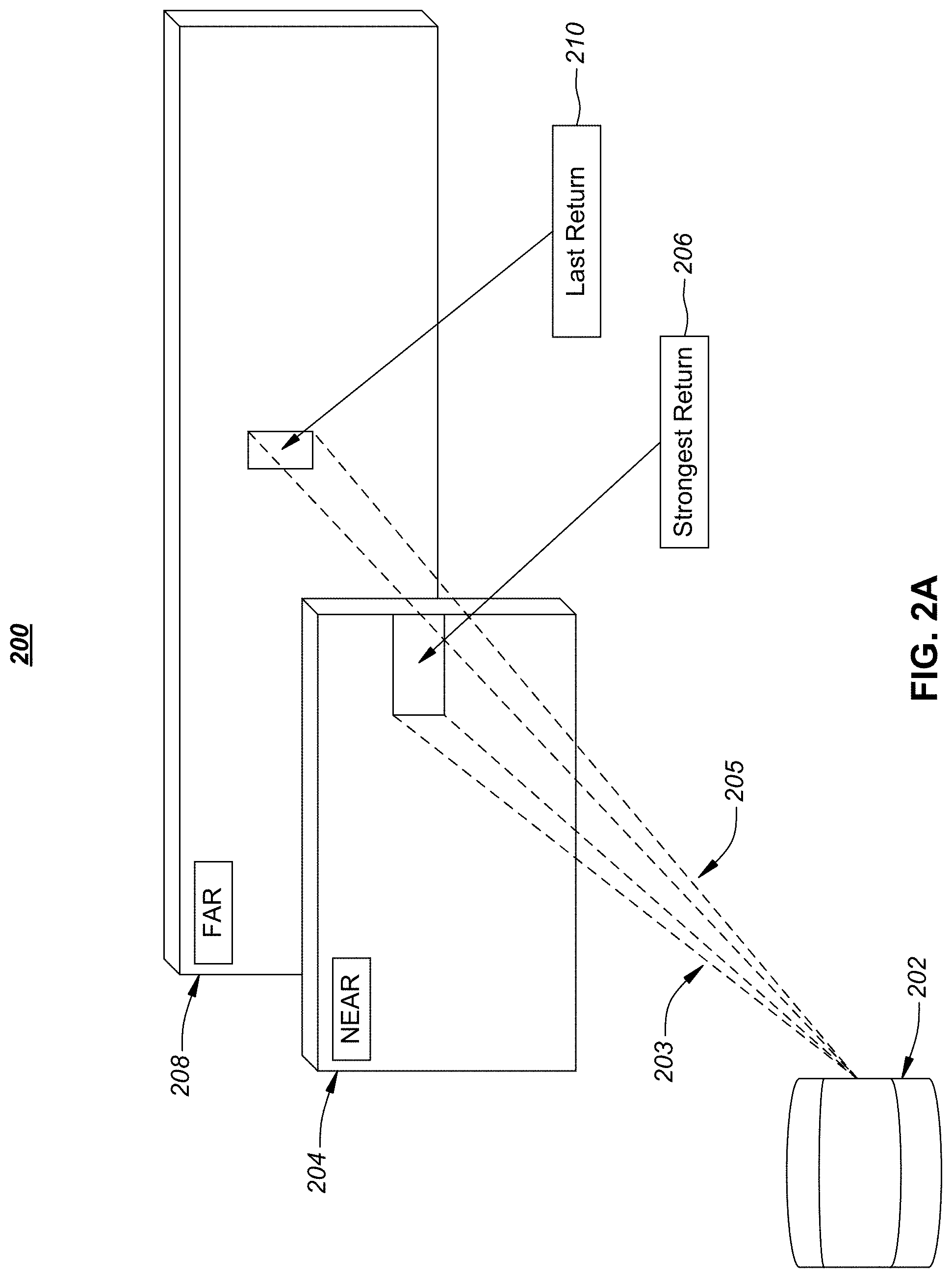
[0008] FIG. 2A illustrates the operation of a light detection and ranging system and multiple return light signals according to embodiments of the present document.
[0009] FIG. 2B depicts a LIDAR system with a oscillating mirror according to embodiments of the present document.
[0010] FIG. 3A depicts a distributed sensor system installed in an automobile utilizing a suite of sensors coupled to a microcontroller (MCU) according to embodiments of the present document.
[0011] FIG. 3B depicts the framework for a sensor system according to embodiments of the current disclosure.
[0012] FIG. 3C depicts the operation of an MCU in an autonomous driving system utilizing sensor modules and a sensor bus according to embodiments of the current disclosure.
[0013] FIGS. 3D and 3E illustrate methods for dynamically configuring different sensors and sensor types within an autonomous navigation system according to embodiments of the current disclosure.
[0014] FIG. 3F illustrates a method for updating calibration parameters in a calibration engine according to embodiments of the current disclosure.
[0015] FIG. 4A and FIG. 4B depict configurable sensor architectures according to embodiments of the current disclosure.
[0016] FIG. 4C illustrates a lissajous scan pattern and resolution according to embodiments of the present disclosure. FIGS. 4D, FIG. 4E, and FIG. 4F illustrate scan resolutions for a field of view (FOV) according to embodiments of the present disclosure.
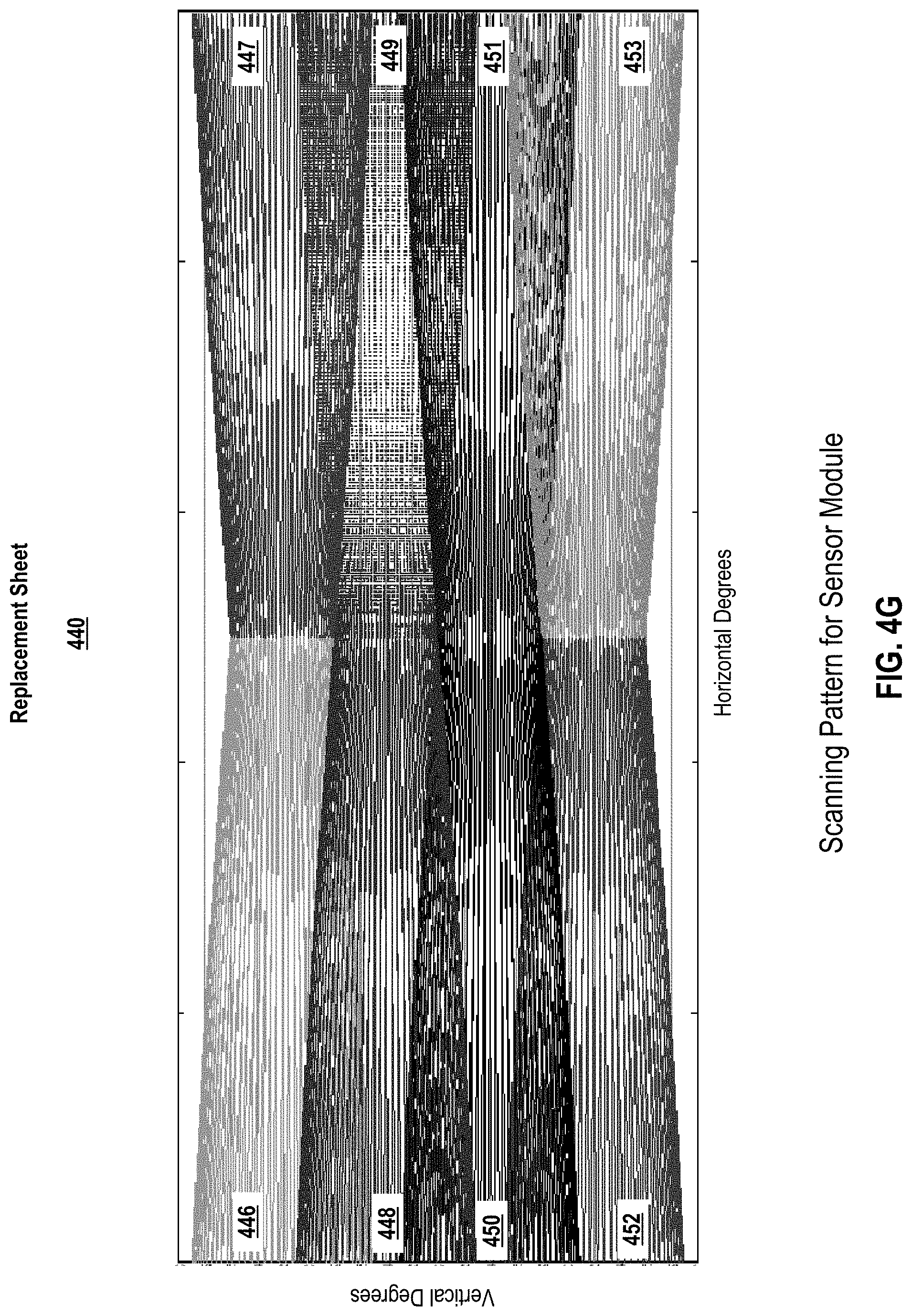
[0017] FIG. 4G illustrates a specific scanning pattern for a sensor module comprising eight sensors according to embodiments of the present disclosure.
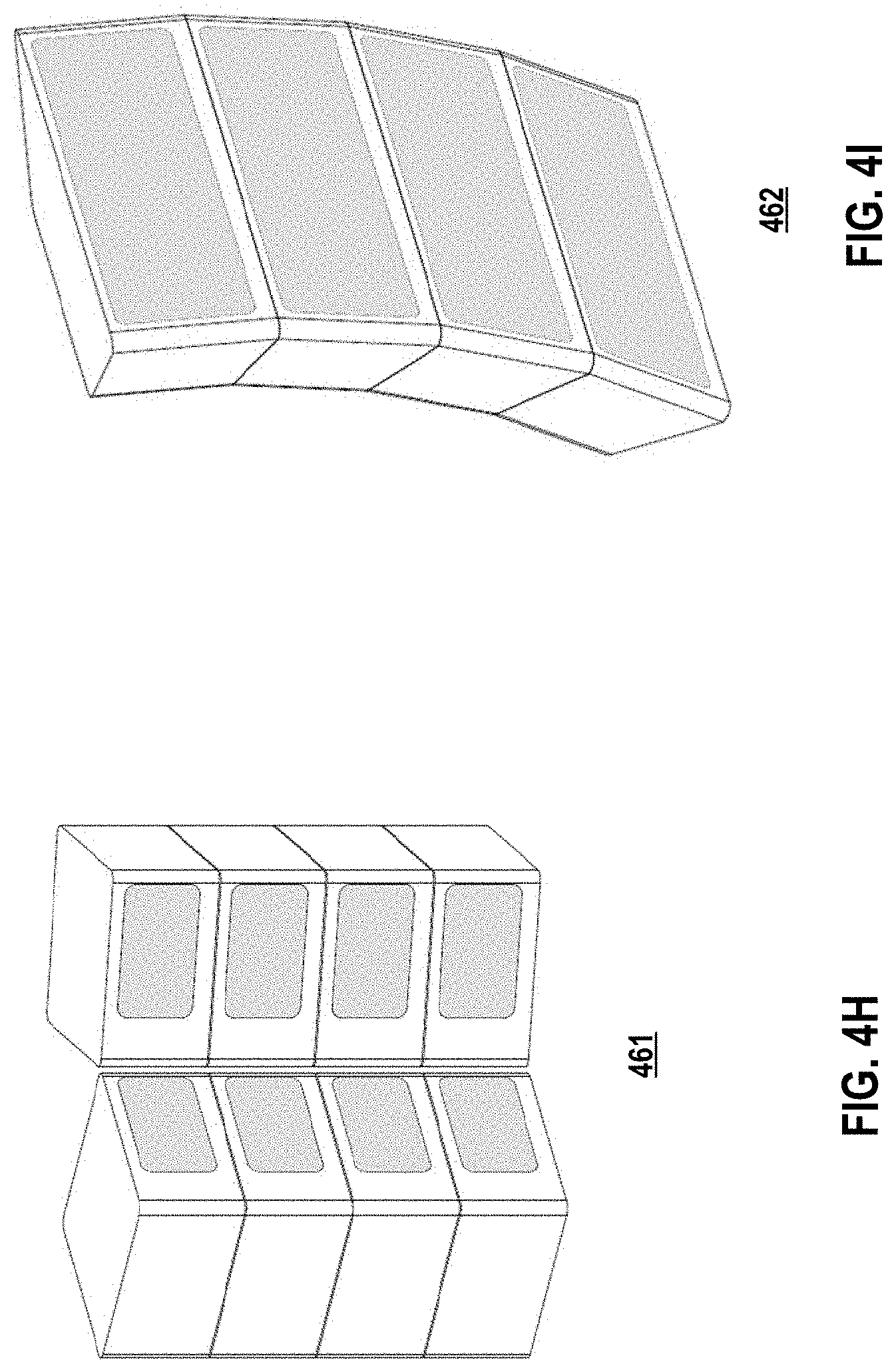
[0018] FIG. 4H and FIG. 4I illustrates exemplary sensor square and pie wedge configurations according to embodiments of the present disclosure.
[0019] FIG. 4J illustrates a sensor system that supports detection of objects with various sensor types including LIDAR, infrared radiation (IR), ambient light modalities to detect range, reflectivity, temperature and color respectively according to embodiments of the present disclosure.
[0020] FIG. 5A depicts a scanning mirror assembly according to embodiments of the present disclosure.
[0021] FIG. 5B depicts a scanning mirror assembly with additional secondary axis coil magnets positioned on a scanner base 512 according to embodiments of the present document.
[0022] FIG. 6 depicts a primary access tensioning mechanism for a scanning mirror according to embodiments of the present disclosure.
[0023] FIG. 7 depicts optical position sensor for a scanning mirror according to embodiments of the present document.
[0024] FIG. 8 depicts ever-orthogonal electromagnetic drive coils according to embodiments of the present document.
[0025] FIG. 9 depicts coaxial drive coils and propulsion magnets according to embodiments of the present document.
[0026] FIG. 10 graphically illustrates a method of determining the real time mirror position for a scanning mirror according to embodiments of the present document.
[0027] FIG. 11 depicts a simplified block diagram of a computing device/information handling system for an automotive application, in accordance with embodiments of the present document.
DETAILED DESCRIPTION OF EMBODIMENTS
[0028] In the following description, for purposes of explanation, specific details are set forth in order to provide an understanding of the invention. It will be apparent, however, to one skilled in the art that the invention can be practiced without these details. Furthermore, one skilled in the art will recognize that embodiments of the present invention, described below, may be implemented in a variety of ways, such as a process, an apparatus, a system, a device, or a method on a tangible computer-readable medium.
[0029] Components, or modules, shown in diagrams are illustrative of exemplary embodiments of the invention and are meant to avoid obscuring the invention. It shall also be understood that throughout this discussion that components may be described as separate functional units, which may comprise sub-units, but those skilled in the art will recognize that various components, or portions thereof, may be divided into separate components or may be integrated together, including integrated within a single system or component. It should be noted that functions or operations discussed herein may be implemented as components. Components may be implemented in software, hardware, or a combination thereof.
[0030] Furthermore, connections between components or systems within the figures are not intended to be limited to direct connections. Rather, data between these components may be modified, re-formatted, or otherwise changed by intermediary components. Also, additional or fewer connections may be used. It shall also be noted that the terms "coupled," "connected," or "communicatively coupled" shall be understood to include direct connections, indirect connections through one or more intermediary devices, and wireless connections.
[0031] Reference in the specification to "one embodiment," "preferred embodiment," "an embodiment," or "embodiments" means that a particular feature, structure, characteristic, or function described in connection with the embodiment is included in at least one embodiment of the invention and may be in more than one embodiment. Also, the appearances of the above-noted phrases in various places in the specification are not necessarily all referring to the same embodiment or embodiments.
[0032] The use of certain terms in various places in the specification is for illustration and should not be construed as limiting. A service, function, or resource is not limited to a single service, function, or resource; usage of these terms may refer to a grouping of related services, functions, or resources, which may be distributed or aggregated.
[0033] The terms "include," "including," "comprise," and "comprising" shall be understood to be open terms and any lists the follow are examples and not meant to be limited to the listed items. Any headings used herein are for organizational purposes only and shall not be used to limit the scope of the description or the claims. Each reference mentioned in this patent document is incorporate by reference herein in its entirety.
[0034] Furthermore, one skilled in the art shall recognize that: (1) certain steps may optionally be performed; (2) steps may not be limited to the specific order set forth herein; (3) certain steps may be performed in different orders; and (4) certain steps may be done concurrently.
[0035] A light detection and ranging system, such as a LIDAR system, may be a tool to measure the shape and contour of the environment surrounding the system. LIDAR systems may be applied to numerous applications including both autonomous navigation and aerial mapping of a surface. LIDAR systems emit a light pulse that is subsequently reflected off an object within the environment in which a system operates. The time each pulse travels from being emitted to being received may be measured (i.e., time-of-flight "TOF") to determine the distance between the object and the LIDAR system. The science is based on the physics of light and optics.
[0036] In a LIDAR system, light may be emitted from a rapidly firing laser. Laser light travels through a medium and reflects off points of things in the environment like buildings, tree branches and vehicles. The reflected light energy returns to a LIDAR receiver (detector) where it is recorded and used to map the environment.
[0037] FIG. 1 depicts operation 100 of a light detection and ranging components 102 and data analysis & interpretation 109 according to embodiments of the present document. Light detection and ranging components 102 may comprise a transmitter 104 that transmits emitted light signal 110, receiver 106 comprising a detector, and system control and data acquisition 108. Emitted light signal 110 propagates through a medium and reflects off object 112. Return light signal 114 propagates through the medium and is received by receiver 106. System control and data acquisition 108 may control the light emission by transmitter 104 and the data acquisition may record the return light signal 114 detected by receiver 106. Data analysis & interpretation 109 may receive an output via connection 116 from system control and data acquisition 108 and perform data analysis functions. Connection 116 may be implemented with a wireless or non-contact communication method. Transmitter 104 and receiver 106 may include optical lens and mirrors (not shown). Transmitter 104 may emit a laser beam having a plurality of pulses in a particular sequence. In some embodiments, light detection and ranging components 102 and data analysis & interpretation 109 comprise a LIDAR system. A design element of receiver 106 is a horizontal field of view (FOV) and a vertical field of view (FOV). In some embodiments, the horizontal FOV is 60 degrees and vertical FOV is 10 degrees. In other embodiments, the horizontal FOV is 120 degrees and vertical FOV is 40 degrees. The FOV may be considered a scanning area for a LIDAR system.
[0038] FIG. 2A illustrates the operation 200 of light detection and ranging system 202 including multiple return light signals: (1) return signal 203 and (2) return signal 205 according to embodiments of the present document. Light detection and ranging system 202 may be a LIDAR system. Due to the laser's beam divergence, a single laser firing often hits multiple objects producing multiple returns. The light detection and ranging system 202 may analyze multiple returns and may report either the strongest return, the last return, or both returns. Per FIG. 2A, light detection and ranging system 202 emits a laser in the direction of near wall 204 and far wall 208. As illustrated, the majority of the beam hits the near wall 204 at area 206 resulting in return signal 203, and another portion of the beam hits the far wall 208 at area 210 resulting in return signal 205. Return signal 203 may have a shorter TOF and a stronger received signal strength compared with return signal 205. Light detection and ranging system 202 may record both returns only if the distance between the two objects is greater than minimum distance. In both single and multiple return LIDAR systems, it is important that the return signal is accurately associated with the transmitted light signal so that an accurate TOF is calculated.
[0039] Some embodiments of a LIDAR system may capture distance data in a 2-D (i.e. single plane) point cloud manner. These LIDAR systems may be often used in industrial applications and may be often repurposed for surveying, mapping, autonomous navigation, and other uses. Some embodiments of these devices rely on the use of a single laser emitter/detector pair combined with some type of moving mirror to effect scanning across at least one plane. This mirror not only reflects the emitted light from the diode, but may also reflect the return light to the detector. Use of a oscillating mirror in this application may be a means to achieving 90-180-360 degrees of azimuth (horizontal) view while simplifying both the system design and manufacturability. Many applications require more data than just a single 2-D plane. The 2-D point cloud may be expanded to form a 3-D point cloud, where multiple 2-D clouds are used, each pointing at a different elevation (vertical) angle. Design elements of the receiver of light detection and ranging system 202 include the horizontal FOV and the vertical FOV.
[0040] FIG. 2B depicts a LIDAR system 250 with a oscillating mirror according to embodiments of the present document. LIDAR system 250 employs a single laser emitter/detector combined with a oscillating mirror to effectively scan across a plane. Distance measurements performed by such a system are effectively two-dimensional (i.e., planar), and the captured distance points are rendered as a 2-D (i.e., single plane) point cloud. In some embodiments, but without limitations, oscillating mirrors are oscillated at very fast speeds e.g., thousands of revolutions per minute. A oscillating mirror may also be referred to as a spinning mirror.
[0041] LIDAR system 250 comprises laser electronics 252, which comprises a single light emitter and light detector. The emitted laser signal 251 may be directed to a fixed mirror 254, which reflects the emitted laser signal 251 to oscillating mirror 256. As oscillating mirror 256 "rotates", the emitted laser signal 251 may reflect off object 258 in its propagation path. The reflected signal 253 may be coupled to the detector in laser electronics 252 via the oscillating mirror 256 and fixed mirror 254. Design elements of the receiver of LIDAR system 250 include the horizontal FOV and the vertical FOV, which defines a scanning area.
[0042] FIG. 3A depicts a distributed sensor system 300 installed in an automobile utilizing a suite of sensors coupled to an MCU 302 according to embodiments of the present disclosure. The suite of sensors includes sensor module 304, sensor module 306, sensor module 308, sensor module 310 and sensor module 312. The term "sensor module" is intended to be broadly defined and includes implementations of single sensor modules and multi-sensor modules. In addition, the types of sensor(s) within a sensor module may vary depending on the configuration of the system. In certain instances, a sensor module may comprise a single sensor (hereinafter, "single sensor module") such as a LiDAR sensor or multiple sensors (hereinafter, "multi-sensor module"). A multi-sensor module may comprise a plurality of integrated sensors, a plurality of discrete sensors or a combination thereof. The multi-sensor module may also comprise a plurality of LiDAR sensors or a plurality of different types of sensors that are correlated within the module. As shown in FIG. 3A, the suite of sensor modules may be distributed in a variety of location on the vehicle. Correlated sensor data from the various sensor modules are provided to the MCU 302 for analysis and decision processing. The connectivity between the sensor modules and the MCU 302 is provided by a sensor bus that may transmit the different sensor data in a serial manner (there may be other embodiments in which sensor data is transmitted on a parallel bus).
[0043] As previously described, a sensor module may comprise a single sensor or multiple sensors and support various types of sensors such as a LIDAR transceiver, thermal/far IR sensor, visible/near IR sensor or other types of sensor known to one of skill in the art. The sensor structure may have various shapes including a modular design that is rectangular or a wedge shaped that may be tiled together and/or stacked and may allow for a design that can go around corners. These different sensor shapes allow configurability of the sensor module including configurability of FOV, sensor range, etc. Based on the particular configuration of the sensor module and corresponding FOV, different scan patterns and resolutions may be implemented.
[0044] MCU 302 may be coupled to an Autonomous Driving System Control Unit (hereinafter, "ADSCU") 301. In certain embodiments, the ADSCU 301 may provide sensor instructions and information to MCU 302.
[0045] FIG. 3B depicts the framework for a sensor system 320 according to embodiments of the current disclosure. Sensor system 322 may be supported by MCU 324 and its associated software. Sensor system 322 may include scan mirror 326, ASICs 328, firmware 330 and sensors 332. In some embodiments, scan mirror 326 may be a dual axis resonant scanning mirror. In some embodiments, sensors 332 may support a combination of sensor modules as described above and may include various sensor types including LIDAR, Color (RGB), thermal (Far-IR) or other sensor types known to one of skill in the art. The sensor system 320 is able to receive data signals from a combination of sensor modules, correlate the sensor data and timely process the correlated sensor data in order to make timely decisions based thereon.
[0046] In order for autonomous vehicles to perceive their surrounding environment and react accordingly, a plurality of techniques may be applied to the sensor system to collate data from the multiple sensor modules. In particular, it may be necessary to collate the data from the sensor modules for dynamic and spatial analysis/inference, which means their differences are decoupled, and digital information can be transmitted, stored and computed in a way that the vehicles and its operating system efficiently process and act on the different sensor data. In this regard, data from the distributed sensors can be multiplexed to provide a unified data packet and coupled via a sensor bus to a microcontroller.
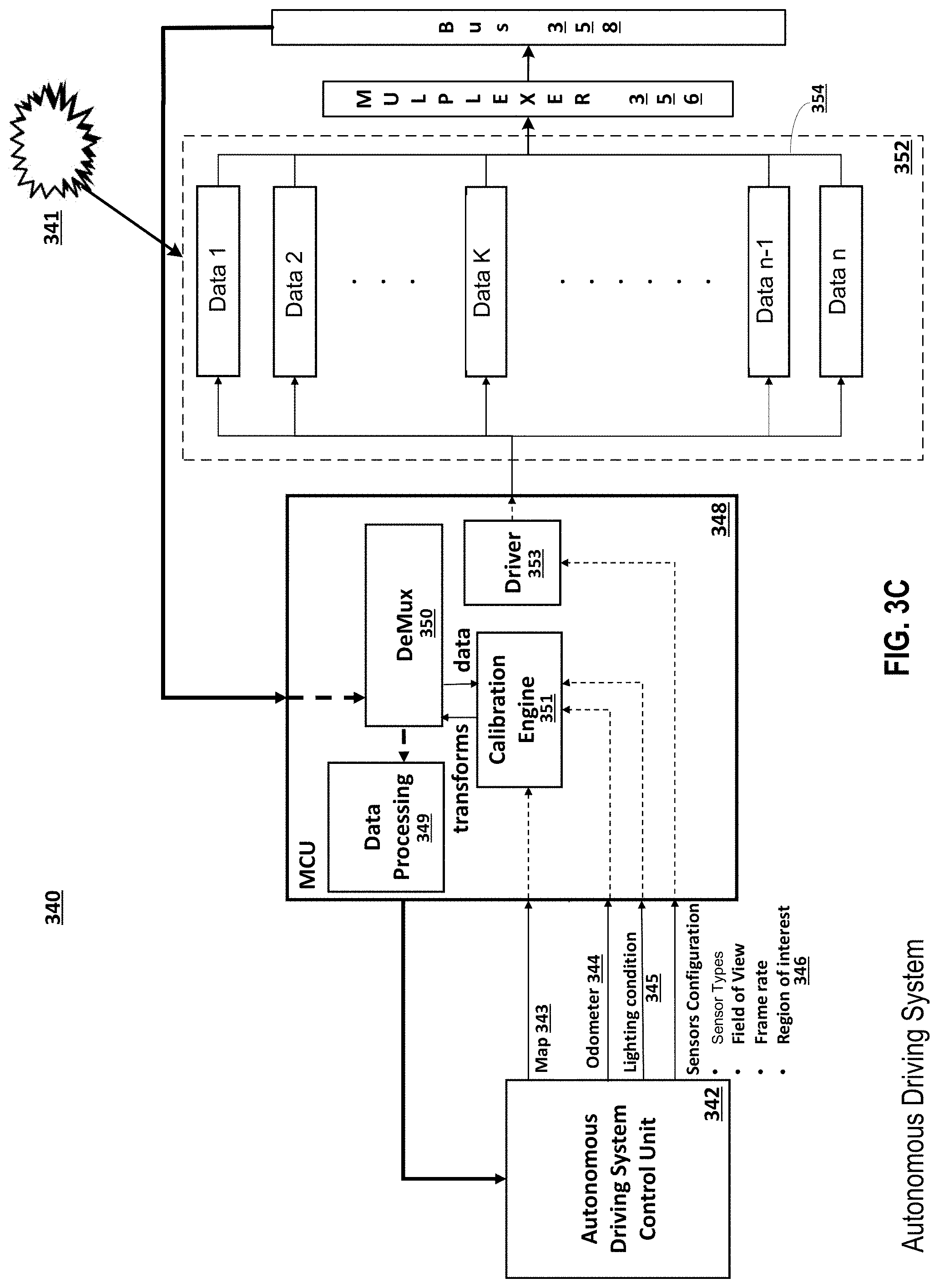
[0047] FIG. 3C depicts the operation of an MCU 348 in an autonomous driving system 340 utilizing sensor module 352 and bus 358 according to embodiments of the disclosure. As illustrated, an object 341 within the autonomous navigation environment is detected by one or more sensor modules 352. As previously described, the structure and type of sensor(s) within the sensor module 352 may vary based on design and/or preference.
[0048] The autonomous driving system 340 may support multiple configurations and redundancies based on the number, types and locations of sensor modules 352 installed around the vehicle. Sensor modules 352 may be activated based on the application and external conditions. For example, when an automobile is being driven on an open highway a fewer number of sensors and/or sensor modules may be activated relative to when an automobile is being driven within heavy traffic. Additionally, sensors and/or sensor modules may be activated based on a particular mode in which an automobile is operating. For example, particular sensors may be activated if a vehicle is operating is a pilot mode as compared to an autonomous mode. This dynamic activation of sensors is another aspect of the configurability of the sensor network, which allows the system to be dynamically adapted to its environment both at installation as well as during operation.
[0049] Sensor module(s) 352 may detect an object 341 across a plurality of sensors and separately couple their detected data signals (shown as data streams 1 thru n) 354 to multiplexer 356. Multiplexer 356 combines the channels of different sensed data and generates a unified data packet correlating the data from each of the sensors. In some embodiments, the unified data packet comprises range and reflectivity data from LIDAR transceiver, color/RGB data from a camera, temperature data from a far infrared detector. In other embodiments, other sensor types from other region of electromagnetic spectrum such as acoustics, radar or sonar may be included. One skilled in the art will recognize that the sensor module 352 may include various combinations of sensor module(s), sensor types and sensor configurations. The unified data packet is coupled to a bus 358, which is typically serial but may also be parallel in nature.
[0050] The data from the multiple sensors and/or sensor modules may be multiplexed and coupled via bus 358 to a microcontroller MCU 348. MCU 348 interacts with an autonomous driving system control unit (hereinafter, "ADSCU") 342 to receive the configuration and parameters for data acquisition from sensors.
[0051] In certain embodiments, the MCU 348 may receive external conditions and information about the motion of the car. MCU 348 comprises data processing element 349, demultiplexer 350, calibration engine 351 and driver 353. In certain embodiments where the bus is serial, the de-multiplexer 350 receives the data serially from multiple sensor modules and uses the calibration parameter from the calibration engine to transform the data as if it is coming from a sensor (i.e., on a sensor channel basis). Calibration engine 351 provides the transforms between different sensors and/or sensor modules. In certain examples, these transforms are initialized to factory settings and constantly updated over time. The data processing element 349 comprises single or multiple embedded algorithms for computing information such as object detection, velocity estimation, localization to roads and external maps. Driver 353 is responsible for activating the sensors and/or sensor modules of interest, and also providing the clock triggers.
[0052] The demultiplexer 350 de-multiplexes the unified serial data packet of sensor data and associates the data with a corresponding sensor and/or sensor module. Thereafter, this data is provided to the calibration engine 351, which generates transform information based on calibration parameters received from ADSCU 342. The demultiplexer 350 also receives the spatial transform information and integrates it with the de-multiplexed unified serial data packet of sensor data into a particular format such as a point cloud format.
[0053] As previously noted in FIG. 3A, the ADSCU 342 may provide sensor instructions to MCU 302. In certain embodiments, ADSCU 342 is the computer in the automobile and is an element manufactured into the vehicle. As shown in FIG. 3C, ADSCU 342 receives an input in the form of a point cloud from data processing 349, a component of MCU 348. In certain embodiments, the ADSCU 342 may generate calibration parameters maps 343, odometer 344, and lighting conditions 345. Other embodiments may have other calibration parameters and utilize a different mix of calibration parameters. In yet other embodiments, the odometer, lighting conditions and external map may be provided to the MCU 348 from another device within the vehicle. ADSCU 342 may also generate sensor configurations 346 including sensor type configurations, field of view, frame rate and region of interest. The region of interest may be, for example, a pedestrian crosswalk or a driving lane. Via a region of interest identification method, the autonomous driving system 340 can filter out amounts of unwanted raw data for the actual tracking. Effectively, MCU 348 homogenizes and decouples the different types of sensor data. With dynamic feedback from the ADSCU 342 in the form of calibration parameters and sensor configuration, MCU 348 can dynamically configure sensors and /or sensor modules across different configurations and space in an autonomous automobile environment.
[0054] FIGS. 3D and 3E illustrate methods 360 and 361 for dynamically configuring multi-sensor modules across different types of sensors and space according to embodiments of the current disclosure comprises the following steps:
[0055] Receive at MCU (Driver) sensor configuration parameters and receive at MCU (calibration engine) calibration parameters from ADSCU (step 362)
[0056] Send from MCU (Driver) configuration parameters to activate selective single sensor module or multi-sensor modules (step 364)
[0057] Acquire data from an object within the environment by the selected sensor module(s) (step 366)
[0058] Multiplex the sensor data to generate a unified data packet (step 368)
[0059] Send the unified data packet via a bus to MCU (step 370)
[0060] In the MCU, de-multiplex unified data packet into homogeneous sensor data (step 372)
[0061] In the MCU, send the homogeneous sensor data to a calibration engine (step 374)
[0062] In the MCU, generate transform information in the calibration engine and send transform information to de-multiplexer (step 376)
[0063] In the MCU, integrate, by the de-multiplexer, the homogeneous sensor data and the transform data, and send to data processing (step 378)
[0064] Generate by data processing of the MCU, a point cloud comprising the homogeneous sensor data and the transform data and send to ADSCU (step 380)
[0065] In the ADSCU, determine/adjust control of the vehicle based on the point cloud and generate updated sensor configurations and calibration parameters (step 382)
[0066] Repeat step 362
[0067] FIG. 3F illustrates a method 390 for updating calibration parameters in a calibration engine according to embodiments of the current disclosure comprises the following steps:
[0068] Receive the homogeneous sensor data from de-multiplexer (step 392)
[0069] Receive calibration parameter data from ADSCU (step 394)
[0070] Update calibration parameters in calibration engine and generate transform information (step 396)
[0071] The above description illustrates the configurability of autonomous navigation at a system level including the activation of certain sensors and/or sensor modules as well as the correlation of data across these sensors and sensor modules. In another aspect of the invention, each sensor module may be configured to operate in accordance with a preferred set of parameters.
[0072] FIG. 4A depicts sensor module 400 and FIG. 4B depicts sensor module 402 from which configurable operational parameters may be defined. This configurability not only allows for FOV definition but also sensor type configuration within a sensor module. Additionally, this configurability may be implemented at installation or in real-time during operation of the system. According to various embodiments, the sensor modules may be configured by defining directionality of one or more sensors within the sensor module using the physical structure of the sensor or by the inclusion of directionality elements (e.g., wedges) that define a direction of a corresponding sensor. As shown in FIG. 4B, sensor module 402 may comprise a plurality of sensors 406-413 that are coupled together in particular architecture such that a combination of individual sensor FOVs is stitched together to create a broader FOV of the sensor module. This configurability of sensor modules allows a user to effectively build unique sensor modules by combining the different sensors into diverse architectures. The configurability is further enhanced by the ability to include different sensor types within the sensor module to enhance performance relative to environmental characteristics in which the module operates.
[0073] A sensor module 402 has a horizontal FOV and vertical FOV that corresponds to the combination of sensors 406-413. The operational characteristics of each sensor 406-413 within the module 402 are combined to provide an enhanced modular FOV. These operational characteristics include the directionality of a sensor, the range of a sensor, the FOV of a sensor, the type of a sensor and other characteristics known to one of skill in the art. In certain embodiments, particular sensors within a module may be activated or deactivated depending on the environment in which the system is operating. In addition, particular sensors may function as redundant elements in case one or more of the sensors fails or becomes temporarily inoperable. The FOV of the sensor module not only depends on the specific operational characteristics of each sensor but also on the manner in which data from these sensors is correlated and combined.
[0074] FIG. 4C illustrates a specific example Lissajous scan pattern and resolution 432 based on different vertical FOVs of a sensor according to embodiments of the present disclosure. Scan 432 illustrates a vertical scan and a horizontal scan resulting from different vertical FOV configurations of a sensor.
[0075] The diagrams on the right side of FIG. 4C illustrate the scan resolutions for different FOVs. FIG. 4D, vFOV 434 illustrates the scan resolution with a 2.5 degree FOV. FIG. 4E, vFOV 436 illustrates the scan resolution with a 5 degree FOV. FIG. 4F, vFOV 438 illustrates the scan resolution with a 10 degree FOV. The resolution achieved with a 2.5 degree FOV is twice as dense as the resolution achieved with a 5 degree FOV. Similarly, the resolution achieved with a 5 degree FOV is twice as dense as the resolution achieved with a 10 degree FOV. This example illustrates the configurability of a sensor and its resultant affect on scan pattern and resolution. One skilled in the art will recognize that numerous patterns and resolutions may be achieved by configuring a sensor in accordance with aspects of the present disclosure.
[0076] The configurability of a sensor module is further enhanced not only by the specific operational parameters of one or more sensors therein, but the manner in which the one or more sensors is combined within the module. FIG. 4G illustrates an exemplary scanning pattern 440 for a sensor system comprising eight sensors within a sensor module according to embodiments of the present disclosure. Scanning pattern 440 may be obtained using sensor module architecture 402 in which data sensed across the eight sensors is combined to provide enhanced resolution and field of view. Scanning pattern 440 comprises scan 446, scan 447, scan 448, scan 449, scan 450, scan 451, scan 452, and scan 453 that are correlated and processed to generate the pattern. In this example, the total field of view for sensor module architecture 402 is approximately 40 degrees by 120 degrees. One skilled in the art will recognize that a diverse of modular FOVs and other module performance characteristics may be achieved by modifying the way in which sensors are coupled together, the specific parameters of the sensors and the methods in which the sensor data is correlated and analyzed.
[0077] FIG. 4H and FIG. 4I illustrates sensor module configurations 461 and 462, respectively, according to various embodiments of the invention. These configurations are intended to be exemplary and not limiting to the scope of the invention. In one embodiment, a sensor module configuration may be a square or rectangle shape, as illustrated in configuration 461, in which individual sensor shapes are configured to provide particular operational characteristics within the module. Configuration 461 comprises two stacked sets of sensors in which physical structures define a FOV for each sensor. For example, physical size and directionality of a sensor may provide different angular and spatial scanning characteristics that are used within the sensor module. As a result, sensor shape and relative locations of the sensors provide a particular scan resolution and FOV. In another configuration, a sensor module configuration may be a wedge shape, as illustrated in configuration 462, in which physical wedge elements define the directionality of sensors within the module. These two examples illustrate to one of skill in the art the vast number of configurable combinations of sensors within a sensor module. In one example, the sensors are LiDAR sensors with corresponding operational characteristics that allow an MCU to build an enhanced scan pattern with preferred resolution. The performance of the sensor system may be further enhanced in some embodiments by the inclusion of different sensor types within a sensor module.
[0078] LIDAR sensors provide unique capabilities for autonomous driving based primarily on the rate and accuracy at which these sensors operate. These LiDAR sensors create an accurate map that can be quickly and unambiguously processed to make rapid navigation decisions with minimal error. However, certain embodiments of the present invention support non-LiDAR sensors that may be included within a sensor module to supplement the LiDAR sensor data. This multi-sensor module employing different types of sensors present unique challenges in the correlation of sensed data across these sensors. Different types of sensors may have different rates of data collection resulting in a more difficult correlation across time. Additionally, different sensors that are closely collocated within the module may be subject to parallax error because data are taken from different vantage points. Accordingly, the use of different types of sensors within a single sensor module further complicates the correlation problem previously described as well as introduces additional complexities within the data analysis and response processing of the system.
[0079] Various embodiments of the invention provide a more efficient manner for sensor data correlation across diverse types of sensors by physically combining the different sensors within a single module package. This multi-sensor module employing different sensors insures that there is a 1:1 correspondence between data points from the various sensors. The sensor data stream can be presented to the autonomous systems with the various sensor-type data, already combined into a correlated data packet. The autonomous system bandwidth can then be focused on the task of navigation rather than preprocessing and correlation of the mixed data sets.
[0080] In one embodiment, consider a LIDAR system that returns a single point from the environment. This single data point is already both a distance measurement (range) as well as an object reflectivity measurement with active illumination. As a further enhancement, the LIDAR detector can also passively measure ambient light from the scene to effectively render a passive grayscale value associated with each LIDAR channel. In a real-world navigation scenario, the color of an object carries important information about its relevance. For example, stop signs and stoplights are red, yellow means caution, green may mean "information" or safe to go and so forth. Providing a unified data packet in which a data point has distance, reflectivity and color provides the autonomous system additional immediate information on the relevance of an object in the field of view
[0081] Another key aspect of the real world is that it is full of living creatures. There are generalized algorithms that attempt to classify detected objects based on size, shape and velocity. However, faults in such algorithms have been demonstrated and may result in errors within the sensor system. One key feature of most living animal creatures that an autonomous system may encounter is that they are warm blooded and generally have a different temperature than their surrounding environment. This characteristic can make it possible to monitor the temperature of objects with various thermal detection technologies. With a thermal sensor incorporated into the LIDAR sensor, yet another data type can be incorporated into the single data packet for each data point reported by the sensor, namely the temperature of the associate object. The ability to instantly classifies the object as a living creature has obvious benefits to rapid autonomous system decision making. The fact that the data are naturally correlated to a real physical object greatly improves both reaction time and certainty of object identification. In certain embodiments, correlation of diverse sensor data may be used to derive a confidence factor of an identified object so that a processed response may take into account the likelihood of an object being one type of object versus another type.
[0082] Thermal sensors provide real-time 3D thermo-spatial information, allowing for more intelligent machine vision. For example, but without limitation, an array of photodetectors sensitive to long IR electromagnetic radiation serving alongside a scanning LIDAR system can simultaneously localize objects in a 3D environment and discriminate warm objects (such as living beings) from other objects in a conventional automotive environment. Active-tracking system can deliver real-time digital information (as opposed to a passive tracking system that delivers a trigger signal) regarding the location and temperature of warm objects to a vehicle control system. A single detector can provide data over a large area by implementing a fast scanning mechanism. A large and dense array of channels can provide thermo-spatial data of in all directions and with high resolution. Furthermore, detectors can be arranged so that the data is both temporally and spatially correlated with the LiDAR channels.
[0083] One skilled in the art will recognize that numerous combinations of sensor types may be included within a sensor module and used to improve the performance of the sensor system. In certain examples, these different sensor types may be used to enhance the performance of a LiDAR system and provide greater accuracy based on certain correlated aspects of sensed data relative to LiDAR data.
[0084] FIG. 4J illustrates a sensor system 480 that supports detection of an object 482 using different types of sensors within a sensor module 484 according to various embodiments of the invention. In this example, a sensor module 484 may comprise various combinations of a LiDAR sensor, thermal/far infrared radiation (IR) sensor, visible/near IR sensor as well as other sensor types known to one of skill in the art. The sensor module 484 receives signals from different sensor types relative to a sensed object 482. The sensor data from each different type of sensor is captured and provided to a multiplexer 488 along corresponding channels 490-494. This data may subsequently be represented on a single cloud point for further processing.
[0085] In a specific example, sensor 484a (Thermal/FarIR Channel) may comprise an array of photodetectors sensitive to long IR electromagnetic radiation. Sensor 484a can simultaneously localize objects in a 3D environment and discriminate warm objects (such as living beings) from other objects in a conventional automotive environment. Sensor 484b (Visible/NearIR Channel) detects RGB color characteristics of ambient light and may also include sensors to detect other light sources such as near infrared light. Sensor 484d may also include a sensor for another region of electromagnetic spectrum such as acoustics, radar or sonar. These sensors 484a, 484b and 484d are used to supplement the LiDAR sensor 484c to provide an enhanced sensor system performance.
[0086] Data multiplexer 488 generates a unified data packet 495 representing the correlated data from the different sensors 484a-d in a unified data packet. The data is correlated in that they are acquired from the same point in space (or nearly the same point and unified in that they are bundled into a single data packet).
[0087] A. Scanning Mirror
[0088] Many sensors, such as LIDAR systems, are implemented with a scanning mirror, as noted in FIG. 2B, LIDAR system 250. While providing a solution for scanning, scanning mirror embodiments may be challenged to achieve performance and cost objectives. Some of the challenges can include: 1) a small dual axis mirror, in which each axis is moving by similar electromagnetic mechanisms can generate crosstalk between each of these electromagnetic mechanisms causing perturbations in the motion; 2) a primary axis may need to be driven independently of the motion of a secondary axis and vice versa. This action may be a challenge because the primary axis motion involves movement of components that are positioned on the secondary axis; 3) a light detector, such as a LIDAR system, may require a feedback mechanism based on where it is scanning at any given moment for assurance of positional accuracy; 4) a scanning mirror assembly, comprising several components, may be mounted to a scanner base via a secondary axis. This structure may make it relatively easy to mechanically induce tension across the secondary axis of resonant spring. However, it may impose challenges in inducing similar tension in the perpendicular (and suspended) primary axis. The tension in each axis is important for isolating and decoupling the motion from the other axis and other external perturbations, such that each axis can be driven with no influence other than its driving mechanism.
[0089] In some embodiments, a dual axis resonant scanning mirror can be an efficient solution for acquiring light signals for these sensor systems and can overcome the aforementioned issues.
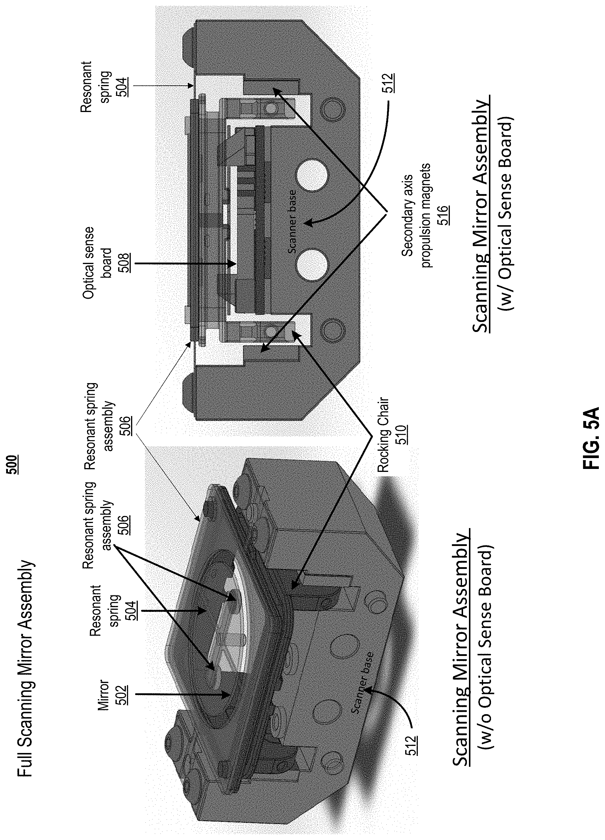
[0090] FIG. 5 depicts a scanning mirror assembly 500 according to embodiments of the present disclosure. Scanning mirror assembly 500 comprises a dual axis resonant scanning mirror. A Sensor module may incorporate an embodiment of scanning mirror assembly 500.
[0091] The scanning mirror assembly 500 may be composed of the resonant spring 504, resonant spring assembly 506, the rocking chair 510 (with electromagnetic drive coils), the scanner base 512 with a set of two secondary axis propulsion magnets 516, the mirror 502 with a spacer and primary axis propulsion magnets 514, and the optical sense board 508. Resonant spring 504 is a component of resonant spring assembly 506. In some embodiments, primary axis 606 (not shown in FIG. 5. See FIG. 6) may be driven to resonate with a frequency around 200 Hz in the horizontal axis based on movement by the primary axis propulsion magnets 514. In other embodiments, primary axis 606 (not shown in FIG. 5. See FIG. 6) may be driven to resonate with a frequency around 125 Hz in the horizontal axis based on movement by the primary axis propulsion magnets 514. The total optical deflection can be +/-30 degrees (60 degrees total). The secondary axis 602 can be selectively controlled via a servomechanism with a maximum optical deflection of +/-5 degrees (10 degrees total) (not shown in FIG. 5. See FIG. 6). The rotation around the secondary axis may be based on the movement of the rocking chair 510 relative to the scanner base 512.
[0092] The resonant spring assembly 506 may be composed of the resonant spring 504 sandwiched in between two frames (coefficient of thermal expansion (CTE) Delta Tensioners), which can create tension across the primary axis upon brazing the assembly, as will be further discussed relative to FIG. 6. The resonant spring assembly 506, mirror 502 (w/ spacer and primary axis propulsion magnets 514), and rocking chair 510 are all suspended by the secondary axis 602 of the resonant spring 504. The resonant spring assembly 506 can be adhered directly to the rocking chair 510, which contains both the primary axis EM drive coil 802 and secondary axis electromagnetic drive coils 806. Hereinafter, "electromagnetic" may be referred to as "EM". These coils will be further discussed relative to FIG. 8.
[0093] Mirror 502 may sit on top of a mechanical spacer which may sit directly on the primary axis of the resonant spring 504. There are two primary axis propulsion magnets 514 that sit underneath mirror 502 with one primary axis propulsion magnet on each side of the primary axis 606. These magnets can drive the motion of the mirror 502 when under the influence of the primary axis EM drive coil's 802 induced EM field. This subject will be further discussed relative to FIG. 8.
[0094] There are two secondary axis EM drive coils 806 which are embedded into the legs of the rocking chair 510 that extend into the `trenches` of the scanner base 512 (shown in FIG. 5. and FIG. 8). This structure places each secondary axis EM drive coils 806 adjacent to a set of two secondary axis propulsion magnets 516 which are stationary and adhered to the scanner base 512. This set of two secondary axis propulsion magnets 516 are oriented with opposite polarity such that as current is passed through the coil, one magnet will attract the coil and the other will repel it. With the attraction and repulsion of each secondary axis coil synced, rocking chair 510 can rotate about the secondary axis of the resonant spring 504.
[0095] FIG. 5B depicts a scanning mirror assembly 550 with additional secondary axis coil magnets 556 positioned on a scanner base 512 according to embodiments of the present document. The secondary axis propulsion magnets 556 are adhered to the scanner base 512 and are positioned on the inside of the legs of the rocking chair 510 to increase the EM interaction and the amount the secondary axis that can be deflected (not shown). Secondary axis propulsion magnets 556 are positioned on scanner base 512 such that their polarity is the same as those as secondary axis propulsion magnets 516 that are positioned on the outside, as illustrated in FIG. 5A. These positioning increases the interaction of the secondary axis coils 806 of FIG. 8, which when embedded into the legs of the rocking chair 510 and placed in the assembly, will sit in between both sets of magnets. When the current flows in one direction, the produced magnetic field will align with the magnets of one polarity and thus attract it, while simultaneously being repelled by the magnets of opposite polarity. These structures are further discussed relative to FIG. 8.
[0096] Inserted through a hole in both the resonant spring 504 and a mirror spacer, there is an optical fiber 706 that may be butted up against mirror 502 (optical fiber 706 not shown in FIG. 5. See FIG. 7). Optical fiber 706 may be impregnated with a dye that fluoresces in a visible wavelength when exposed to UV light. The fluoresced light is then guided down optical fiber 706 and illuminates a region of a PSD 710 (position sensitive detector), that may sit on scanner base 512, which can provide real time mirror position sensing. This structure is further discussed relative to FIG. 7.
[0097] A sensor system that incorporates scanning mirror assembly 500 can provide a single channel subsystem. In some embodiments, this subsystem is facilitated via Sensor 400 and Sensor 401 of FIG. 4A. Sensor 400 and Sensor 401 can support a scan field maximum of approximately 60.times.10 degrees, and a scan field minimum of approximately 60.times.2.5 degrees.
[0098] An 8 channel composite system can incorporate 8 Sensor modules. Each Sensor module incorporates a scanning mirror assembly 500. In some embodiments, this composite system is facilitated via sensor architecture 402 of FIG. 4A. Sensor architecture 402 can support a scan field maximum of approximately 120.times.40 degrees, and a scan field minimum of approximately 120.times.10 degrees.
[0099] In some embodiments, the Sensor module may have a firing rate of 160 kHz, a range of approximately 100 meters, a mean resolution of 0.1 degrees minimum, and a spot divergence of 0.5 mRad. All values are approximate. In other embodiments, the firing rate may be 400 kHz.
[0100] B. Primary Access Tensioning Mechanism for Resonant Spring Assembly
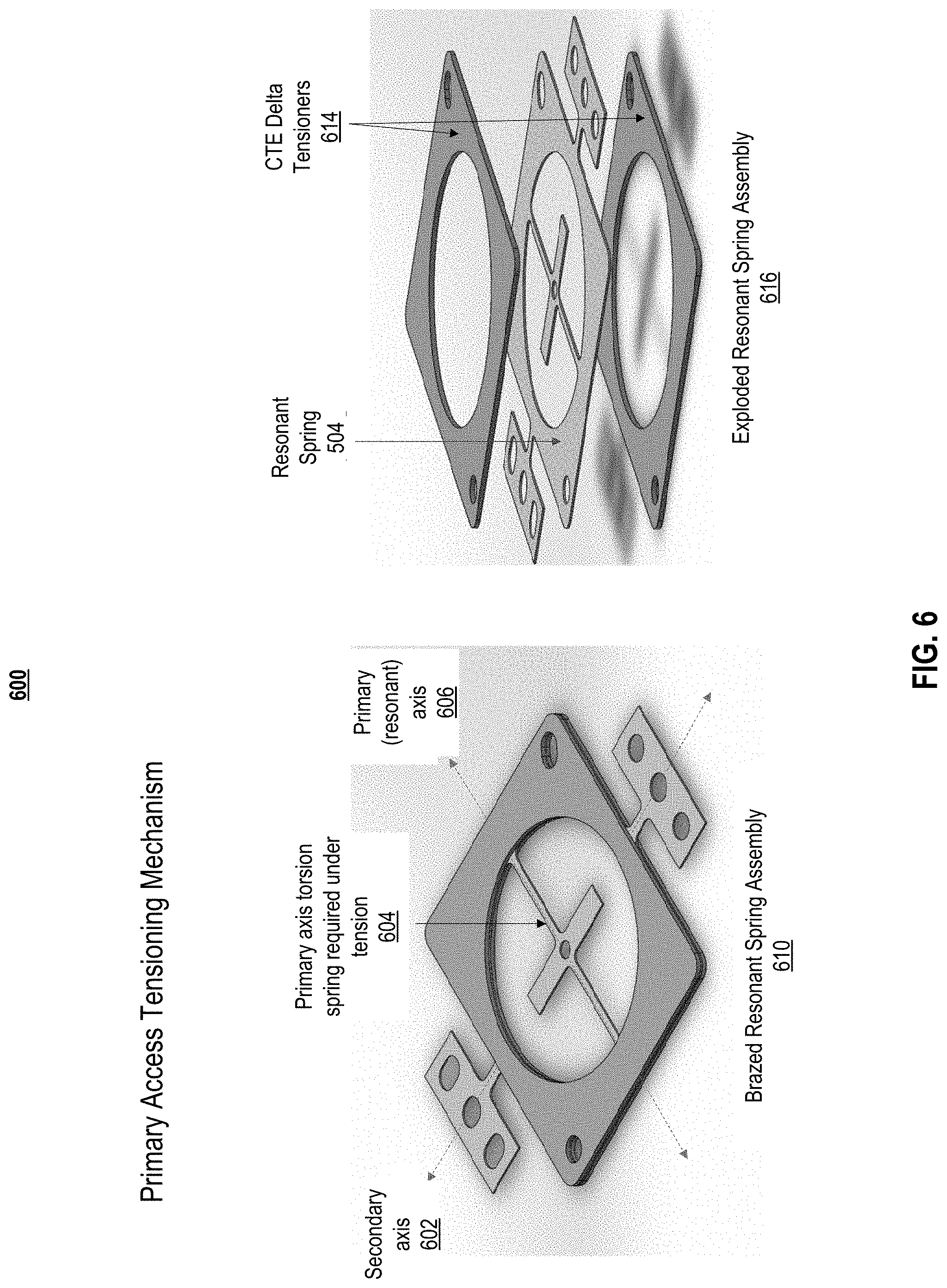
[0101] FIG. 6 depicts a primary access tensioning mechanism 600 for a scanning mirror according to embodiments of the present disclosure. The scanning mirror assembly 500 of FIG. 5, the resonant spring assembly 506, along with the components adhered to it (rocking chair 510, mirror 502 with spacer, magnets, and coils), is mounted to scanner base 512 via the secondary axis 602. This structure makes it relatively easy to mechanically induce tension across the secondary axis of resonant spring 504. However, the structure may impose challenges with inducing similar tension in the perpendicular (and suspended) primary axis 606. The tension in each axis can be important for isolating and decoupling the motion from the other axis and other external perturbations, such that each axis can be driven with no influence other than its driving mechanism. The primary axis torsion spring required under tensions 604 is illustrated in FIG. 6.
[0102] A solution to this problem may comprise a brazed resonant spring assembly 610 that is devised such that upon soldering/brazing the components together and cooling, tension is induced across the primary axis 606 due to a slight mismatch in CTE (coefficient of thermal expansion). FIG. 6 also illustrates an exploded resonant spring assembly 616, with resonant spring 504 and CTE Delta tensioners 614.
[0103] The brazed resonant spring assembly 610 is composed of the resonant spring 504, which is sandwiched in between two CTE Delta tensioners 614. The CTE Delta tensioners 614 are composed of a material that has a slightly lower CTE than that of resonant spring 504. When the assembly is brazed together at high temperatures, both the tensioners and spring will expand via thermal expansion, and as they start to cool again, they will retract. Once the solidus temperature of the solder/braze material is reached upon cooling, the assembly will be fully adhered, and the two materials will continue to contract. The spring material, since it has a higher CTE, will contract more than the tensioners. Because of the geometry of the tensioner fully surrounding exposed primary axis 606 of the resonant spring 504, and because the ends of the primary axis 606 are anchored once the assembly is cooled below the solidus temperature of the solder/braze material, the relatively greater contraction of the spring material will result in tension across the primary of axis of the resonant spring 504.
[0104] Note that the CTE Delta tensioners 614 need to sandwich the resonant spring 504, otherwise the whole assembly will begin to bow due to the dissimilar CTEs.
[0105] C. Optical Position Sensor
[0106] FIG. 7 depicts optical position sensor 700 for a scanning mirror according to embodiments of the present document. A light detector, such as a LIDAR system, may require a feedback mechanism based on where it is scanning at any given moment for assurance of positional accuracy. This assurance may be achieved in a LIDAR system by sensing the position of mirror 502. Necessary criteria for the sensing mechanism include high accuracy, small form factor, limited or no additional mass to the moving components, and limited or no interaction with the moving components.
[0107] A solution that may meet the aforementioned criteria may comprise an optical position sensor 700 that is composed of components: a dye impregnated into an optical fiber 706, PSD 710, a UV/IR filter 712, UV LED 708, UV LED 709, prism 702, prism 703, and the optical sense PCB. Optical fiber 706 is specifically impregnated with a dye that fluoresces in the visible spectrum when illuminated with UV light. Optical fiber 706 may be inserted though the resonant spring 504 and a mirror spacer, and butted up against the backside of mirror 502 such that its axis is normal to the plane of mirror 502 at all times. Optical fiber 706 may be illuminated with two UV LEDs sitting on the PCB. The UV light can be guided towards optical fiber 706, which is dye impregnated, via prism 702 or prism 703, which sit directly on top of UV LED 708 or UV LED 709, respectively. The number of UV LEDs and prisms may vary in optical fiber embodiments. For example, but without limitation, in one embodiment, there may be only one UV LED and one corresponding prism. In other embodiments, there may be more than two UV LEDs and more than two corresponding prisms.
[0108] When optical fiber 706 fluoresces due to its illumination from the UV LED 708 and UV LED 709, the visible fluoresced light can be guided down optical fiber 706 to PSD 710, which may measure the position of the light spot on its active surface. The position of the light spot on its active surface has a direct relation to the position of mirror 502, and thus a specific position in the point cloud generated by the mirror's scan. A UV/IR filter 712 may be required on top of the PSD 710 in order to filter out the UV light from the UV LEDs as well as the IR light from a laser. The laser may be a component of a LIDAR system. Every component of the optical position sensor 700, except the optical fiber 706, will sit stationary on the scanner base 512. A sensor module may include an embodiment of optical position sensor 700.
[0109] D. Ever-Orthogonal Electromagnetic Drive Coils
[0110] FIG. 8 depicts ever-orthogonal EM drive coils 800 according to embodiments of the present document. A concern with a small dual axis mirror, in which each axis is driving by similar electromagnetic mechanisms, is crosstalk between each of those electromagnetic mechanisms causing perturbations in the motion. As angles and distances change between the drive coils in each axis, their interactions will change, which can affect the forces on each other and the propulsion magnets, and thus the overall motion.
[0111] The manner which rocking chair 510 has been implemented in some embodiments allows for each axes' drive coil(s), and thus their magnetic fields, to always be orthogonal to each other, regardless of the motion of the whole assembly. The primary axis EM drive coil 802 is wrapped around the rocking chair 510 in a groove that is just under the plane which the resonant spring assembly sits on. This coil's magnetic field interacts with two magnets placed on either side of the primary axis 606 under mirror 502.
[0112] The secondary axis EM drive coils 806 are embedded into the legs of rocking chair 510, which extend down into the `trenches` of scanner base 512. This places each secondary axis EM drive coils 806 adjacent to a set of two secondary axis propulsion magnets 516, which are stationary and adhered to scanner base 512. Each set of two secondary axis propulsion magnets 516 are oriented with opposite polarity such that as current is passed through the coil, one magnet will attract the coil and the other will repel it. With the attraction and repulsion of each secondary axis coil synced, rocking chair 510 can rotate about the secondary axis 602 of the resonant spring 504. As previously noted, FIG. 5B depicts a scanning mirror assembly 550 with additional secondary axis coil magnets 556 positioned on a scanner base 512.
[0113] E. Coaxial Drive Coil and Propulsion Magnets
[0114] FIG. 9 depicts coaxial drive coils and propulsion magnets 900 according to embodiments of the present document. FIG. 9 may address the following problem statement: The primary axis needs to be driven independently of the motion of secondary axis 602. This situation is a challenge because secondary axis 602 motion involves "rocking" the rocking chair 510 on which all of the components of the primary axis 606 sit.
[0115] The primary axis EM drive coil 802 may be wound around rocking chair 510 into a groove that is just directly under the plane on which resonant spring assembly 610 is adhered. See drive coil 904. The primary axis propulsion magnets 514 are adhered to the bottom of resonant spring (under each end of the mirror spacer), such that they are both coaxial relative primary axis EM drive coil 802.
[0116] The primary axis propulsion magnets 514 are placed such that they have opposite polarity relative to each other, and sit across primary axis 606 from each other under the mirror 502. When current is passed through primary axis EM drive coil 802, the induced magnetic field forces one magnet up and the other down, which causes the mirror to rotate about the primary axis 606.
[0117] F. Method of Determining Real-Time Mirror Positioning
[0118] FIG. 10 graphically illustrates a method 1000 of determining the real time mirror positioning for a scanning mirror according to embodiments of the present document. The method comprises the steps of:
[0119] Receiving scanning command from MCU. (step 1002)
[0120] Activating scanning in the scanning mirror. (step 1004)
[0121] Receiving a light signal and coupling the light signal to a dye impregnated optical fiber. (step 1006)
[0122] Coupling visible fluoresced light to a position sensitive detector (PSD). (step 1008)
[0123] Determining real time mirror positioning. (step 1010)
[0124] G. Dual Axis Resonant Scanning Mirror System
[0125] In summary, a system for a dual axis resonant scanning mirror may comprise a resonant spring assembly; a rocking chair with electromagnetic drive coils; a scanner base with secondary axis propulsion magnets; a mirror with a spacer and two primary axis propulsion magnets; and an optical position sense assembly. The optical position sense assembly may comprise a dye impregnated optical fiber, a positive sensitive detector, a UV/IR filter, two UV LEDs with two corresponding prisms. When dye in the dye impregnated optical fiber fluoresces due to its illumination from the two UV LEDs, visible fluoresced light may be guided down the dye impregnated optical fiber to the positive sensitive detector, which determines mirror positioning. The positioning of the mirror is indicated by a light spot on an active surface of the positive sensitive detector. In other embodiments, an optical position sensor comprises two or more uv leds with two or more corresponding prisms.
[0126] The system further may comprise: i) a primary axis that resonates at a frequency in an horizontal axis with an primary optical deflection, and ii) a secondary axis that is selectively controlled via a servomechanism to operate in a vertical axis with a secondary optical deflection. The primary axis may be driven independent of motion of the secondary axis, and vice-versa, and the primary axis motion involves movement of components that are positioned on the secondary axis. Moreover, the primary axis may have a maximum primary optical deflection of +/-30 degrees, and the secondary axis may have a maximum secondary optical deflection of +/-5 degrees.
[0127] The resonant spring assembly may comprise a resonant spring sandwiched between two frames that create tension across a primary axis upon brazing the resonant spring assembly. The two frames comprise a coefficient of thermal expansion delta tensioners. The resonant spring assembly, mirror, and rocking chair may be suspended by a secondary axis of the resonant spring. The resonant spring assembly is adhered to the rocking chair, which comprises primary and secondary axis electromagnetic drive coils. The mirror sits on the spacer, which sits directly on the primary axis of resonant springs, and wherein the two primary axis propulsion magnets sit underneath the mirror with one primary axis propulsion magnet on each side of the primary axis.
[0128] The electromagnetic drive coils may comprise a primary axis electromagnetic drive coil and a set of two secondary axis electromagnetic drive coils, and wherein magnetic fields of i) the primary axis electromagnetic drive coil, and ii) the set of two secondary axis electromagnetic drive coils, are orthogonal to each other, regardless of motion of the system. The primary axis electromagnetic drive coil is wrapped around the rocking chair under a plane that a resonant spring sits on, and the magnetic field of the primary axis electromagnetic drive coil interacts with the two primary axis propulsion magnets that are placed on either side of the primary axis under the mirror, causing optical deflection. The set of two secondary axis electromagnetic drive coils synchronize with a set of two secondary axis propulsion magnets, causing the rocking chair to rotate around a second axis of a resonant spring.
[0129] H. System Embodiments
[0130] In embodiments, aspects of the present patent document may be directed to or implemented on information handling systems/computing systems. For purposes of this disclosure, a computing system may include any instrumentality or aggregate of instrumentalities operable to compute, calculate, determine, classify, process, transmit, receive, retrieve, originate, route, switch, store, display, communicate, manifest, detect, record, reproduce, handle, or utilize any form of information, intelligence, or data for business, scientific, control, or other purposes. For example, a computing system may be a personal computer (e.g., laptop), tablet computer, phablet, personal digital assistant (PDA), smart phone, smart watch, smart package, server (e.g., blade server or rack server), a network storage device, or any other suitable device and may vary in size, shape, performance, functionality, and price. The computing system may include random access memory (RAM), one or more processing resources such as a central processing unit (CPU) or hardware or software control logic, ROM, and/or other types of memory. Additional components of the computing system may include one or more disk drives, one or more network ports for communicating with external devices as well as various input and output (I/O) devices, such as a keyboard, a mouse, touchscreen and/or a video display. The computing system may also include one or more buses operable to transmit communications between the various hardware components.
[0131] FIG. 11 depicts a simplified block diagram of a computing device/information handling system (or computing system) according to embodiments of the present disclosure. It will be understood that the functionalities shown for system 1100 may operate to support various embodiments of an information handling system--although it shall be understood that an information handling system may be differently configured and include different components.
[0132] As illustrated in FIG. 11, system 1100 includes one or more central processing units (CPU) 1101 that provides computing resources and controls the computer. CPU 1101 may be implemented with a microprocessor or the like, and may also include one or more graphics processing units (GPU) 1117 and/or a floating point coprocessor for mathematical computations. System 1100 may also include a system memory 1102, which may be in the form of random-access memory (RAM), read-only memory (ROM), or both.
[0133] A number of controllers and peripheral devices may also be provided, as shown in FIG. 11. An input controller 1103 represents an interface to various input device(s) 1104, such as a keyboard, mouse, or stylus. There may also be a wireless controller 1105, which communicates with a wireless device 1106. System 1100 may also include a storage controller 1107 for interfacing with one or more storage devices 1108 each of which includes a storage medium such as magnetic tape or disk, or an optical medium that might be used to record programs of instructions for operating systems, utilities, and applications, which may include embodiments of programs that implement various aspects of the present invention. Storage device(s) 1108 may also be used to store processed data or data to be processed in accordance with the invention. System 1100 may also include a display controller 1109 for providing an interface to a display device 1111, which may be a cathode ray tube (CRT), a thin film transistor (TFT) display, or other type of display. The computing system 1100 may also include an automotive signal controller 1112 for communicating with an automotive system 1113. A communications controller 1114 may interface with one or more communication devices 1115, which enables system 1100 to connect to remote devices through any of a variety of networks including the Internet, a cloud resource (e.g., an Ethernet cloud, an Fiber Channel over Ethernet (FCoE)/Data Center Bridging (DCB) cloud, etc.), a local area network (LAN), a wide area network (WAN), a storage area network (SAN) or through any suitable electromagnetic carrier signals including infrared signals.
[0134] In the illustrated system, all major system components may connect to a bus 1116, which may represent more than one physical bus. However, various system components may or may not be in physical proximity to one another. For example, input data and/or output data may be remotely transmitted from one physical location to another. In addition, programs that implement various aspects of this invention may be accessed from a remote location (e.g., a server) over a network. Such data and/or programs may be conveyed through any of a variety of machine-readable medium including, but are not limited to: magnetic media such as hard disks, floppy disks, and magnetic tape; optical media such as CD-ROMs and holographic devices; magneto-optical media; and hardware devices that are specially configured to store or to store and execute program code, such as application specific integrated circuits (ASICs), programmable logic devices (PLDs), flash memory devices, and ROM and RAM devices.
[0135] Embodiments of the present invention may be encoded upon one or more non-transitory computer-readable media with instructions for one or more processors or processing units to cause steps to be performed. It shall be noted that the one or more non-transitory computer-readable media shall include volatile and non-volatile memory. It shall be noted that alternative implementations are possible, including a hardware implementation or a software/hardware implementation. Hardware-implemented functions may be realized using ASIC(s), programmable arrays, digital signal processing circuitry, or the like. Accordingly, the "means" terms in any claims are intended to cover both software and hardware implementations. Similarly, the term "computer-readable medium or media" as used herein includes software and/or hardware having a program of instructions embodied thereon, or a combination thereof. With these implementation alternatives in mind, it is to be understood that the figures and accompanying description provide the functional information one skilled in the art would require to write program code (i.e., software) and/or to fabricate circuits (i.e., hardware) to perform the processing required.
[0136] It shall be noted that embodiments of the present invention may further relate to computer products with a non-transitory, tangible computer-readable medium that have computer code thereon for performing various computer-implemented operations. The media and computer code may be those specially designed and constructed for the purposes of the present invention, or they may be of the kind known or available to those having skill in the relevant arts. Examples of tangible computer-readable media include, but are not limited to: magnetic media such as hard disks, floppy disks, and magnetic tape; optical media such as CD-ROMs and holographic devices; magneto-optical media; and hardware devices that are specially configured to store or to store and execute program code, such as application specific integrated circuits (ASICs), programmable logic devices (PLDs), flash memory devices, and ROM and RAM devices. Examples of computer code include machine code, such as produced by a compiler, and files containing higher level code that are executed by a computer using an interpreter. Embodiments of the present invention may be implemented in whole or in part as machine-executable instructions that may be in program modules that are executed by a processing device. Examples of program modules include libraries, programs, routines, objects, components, and data structures. In distributed computing environments, program modules may be physically located in settings that are local, remote, or both.
[0137] One skilled in the art will recognize no computing system or programming language is critical to the practice of the present invention. One skilled in the art will also recognize that a number of the elements described above may be physically and/or functionally separated into sub-modules or combined together.
[0138] It will be appreciated to those skilled in the art that the preceding examples and embodiments are exemplary and not limiting to the scope of the present disclosure. It is intended that all permutations, enhancements, equivalents, combinations, and improvements thereto that are apparent to those skilled in the art upon a reading of the specification and a study of the drawings are included within the true spirit and scope of the present disclosure. It shall also be noted that elements of any claims may be arranged differently including having multiple dependencies, configurations, and combinations.
* * * * *
D00000
D00001
D00002
D00003
D00004
D00005
D00006
D00007
D00008
D00009
D00010
D00011
D00012
D00013
D00014

D00015
D00016

D00017
D00018

D00019

D00020

D00021

D00022

XML
uspto.report is an independent third-party trademark research tool that is not affiliated, endorsed, or sponsored by the United States Patent and Trademark Office (USPTO) or any other governmental organization. The information provided by uspto.report is based on publicly available data at the time of writing and is intended for informational purposes only.
While we strive to provide accurate and up-to-date information, we do not guarantee the accuracy, completeness, reliability, or suitability of the information displayed on this site. The use of this site is at your own risk. Any reliance you place on such information is therefore strictly at your own risk.
All official trademark data, including owner information, should be verified by visiting the official USPTO website at www.uspto.gov. This site is not intended to replace professional legal advice and should not be used as a substitute for consulting with a legal professional who is knowledgeable about trademark law.