Sensor Head For Insertion Electromagnetic Flow Meter
Moss; Robert Austin ; et al.
U.S. patent application number 16/239029 was filed with the patent office on 2020-07-09 for sensor head for insertion electromagnetic flow meter. The applicant listed for this patent is DWYER INSTRUMENTS, INC.. Invention is credited to Alejandro Ignacio Baez Guada, Shilei Ma, Jeff Meuili, Robert Austin Moss.
| Application Number | 20200217697 16/239029 |
| Document ID | / |
| Family ID | 71404338 |
| Filed Date | 2020-07-09 |


View All Diagrams
| United States Patent Application | 20200217697 |
| Kind Code | A1 |
| Moss; Robert Austin ; et al. | July 9, 2020 |
SENSOR HEAD FOR INSERTION ELECTROMAGNETIC FLOW METER
Abstract
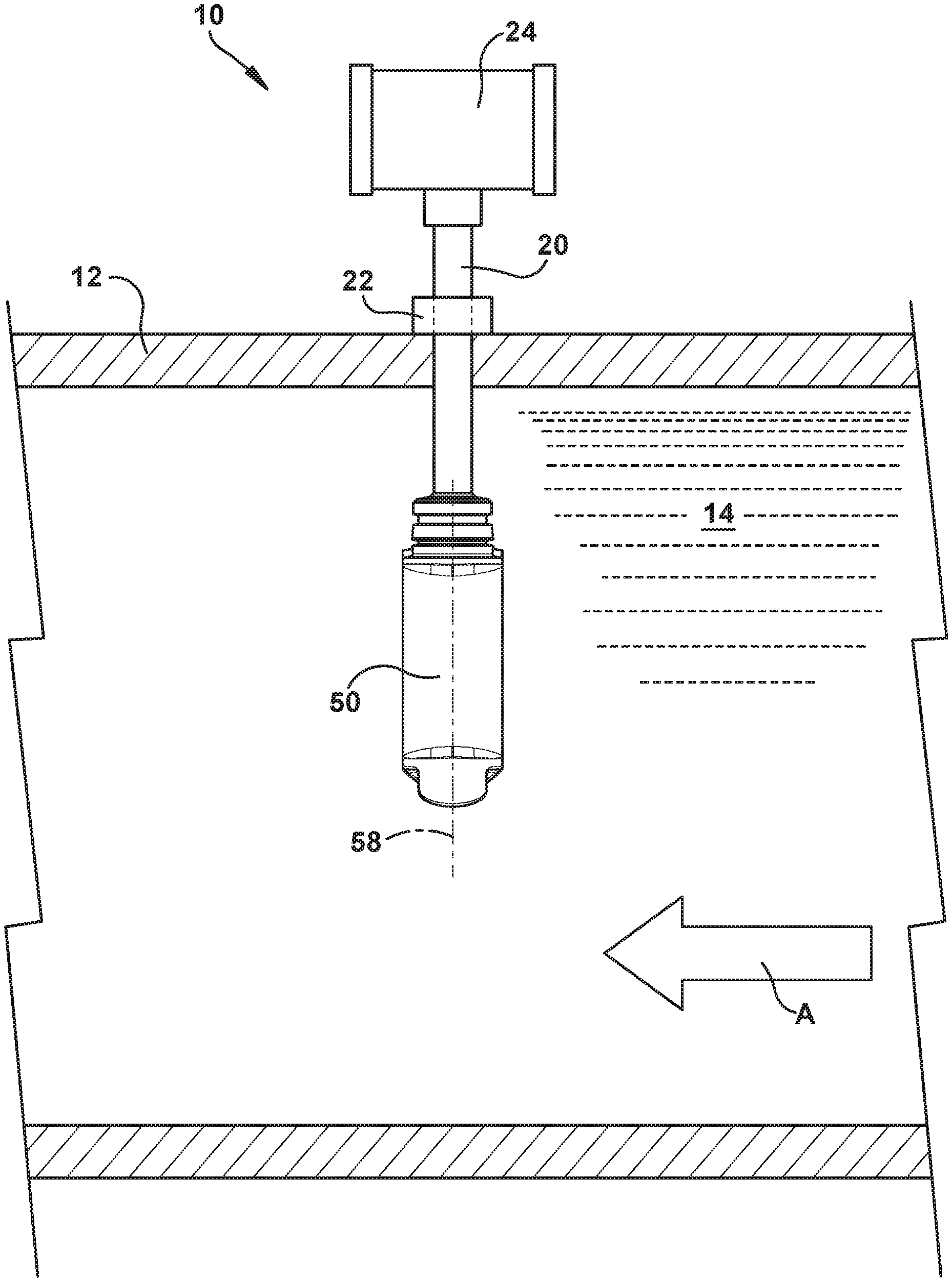
An apparatus for measuring flow in a conduit includes a sensor head configured for insertion transversely through a conduit sidewall to position the sensor head in an electrically conductive fluid flowing through the conduit. The sensor head includes a core and a coil that at least partially surrounds the core, the coil being excitable to generate an electromagnetic field. The sensor head also includes first and second electrodes spaced apart from each other, and a body that supports the coil, core, and electrodes. The body includes at least one channel through which the electrically conductive fluid flows. The electrodes are positioned in the at least one channel. Each channel is defined by opposing sidewalls that have a converging configuration.
| Inventors: | Moss; Robert Austin; (Saint Joseph, MI) ; Guada; Alejandro Ignacio Baez; (Chicago, IL) ; Ma; Shilei; (Wilmette, IL) ; Meuili; Jeff; (LaPort, IN) | ||||||||||
| Applicant: |
|
||||||||||
|---|---|---|---|---|---|---|---|---|---|---|---|
| Family ID: | 71404338 | ||||||||||
| Appl. No.: | 16/239029 | ||||||||||
| Filed: | January 3, 2019 |
| Current U.S. Class: | 1/1 |
| Current CPC Class: | G01F 1/584 20130101; G01F 1/60 20130101; G01F 1/588 20130101; G01F 1/586 20130101 |
| International Class: | G01F 1/58 20060101 G01F001/58; G01F 1/60 20060101 G01F001/60 |
Claims
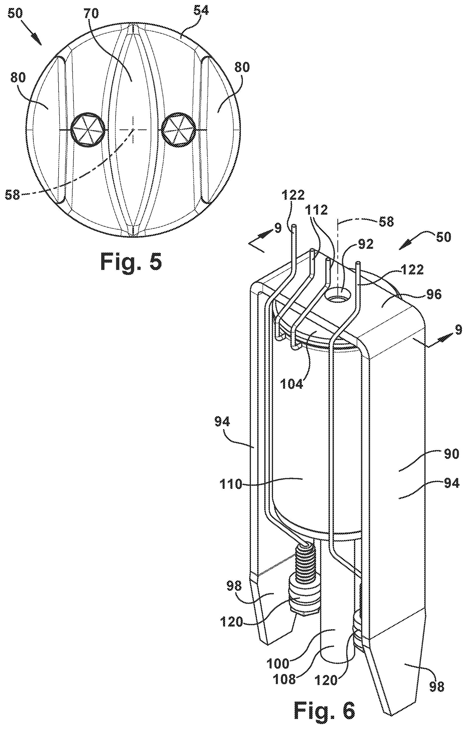
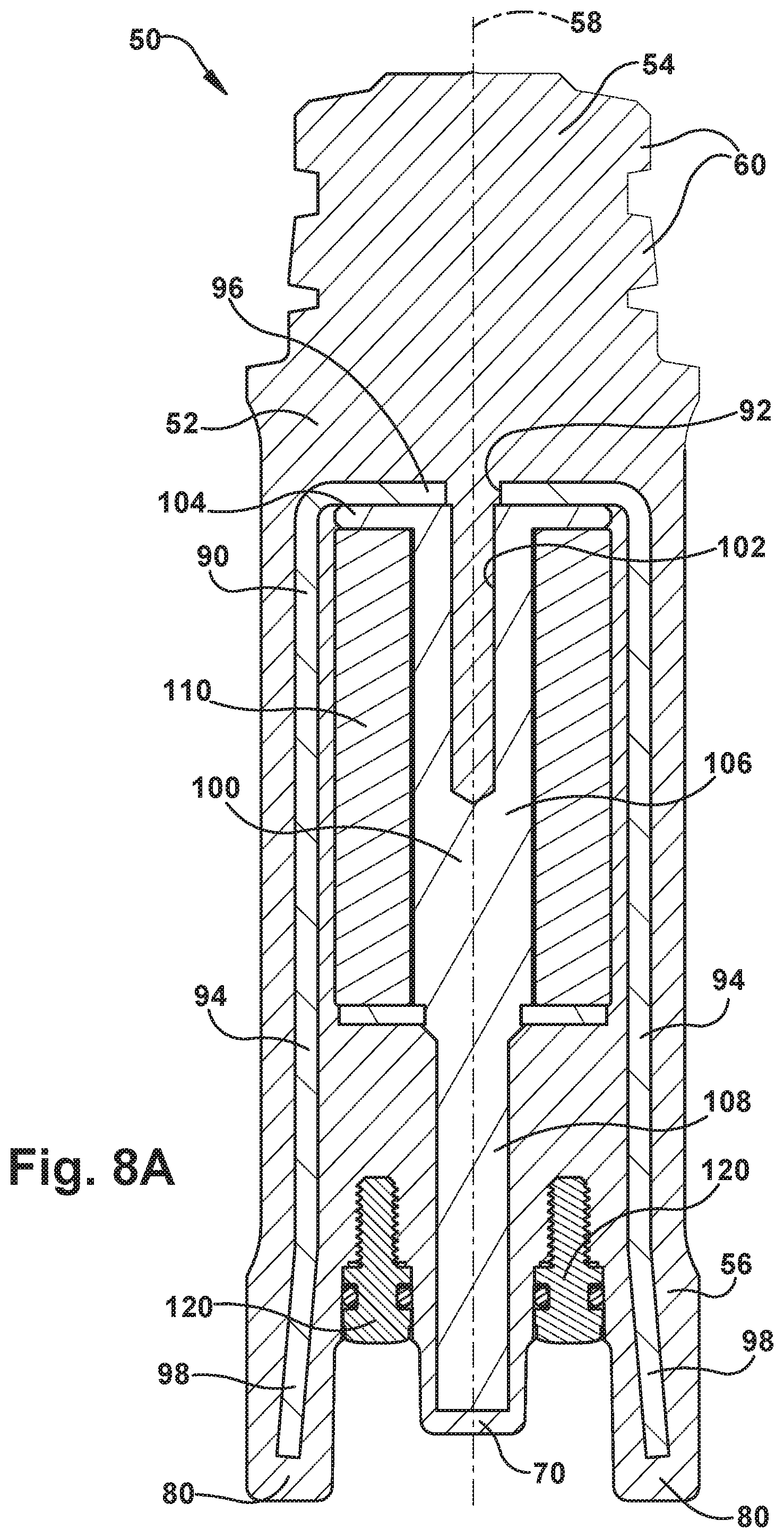
1. An apparatus for measuring flow in a conduit, comprising: a sensor head configured for insertion transversely through a conduit sidewall to position the sensor head in an electrically conductive fluid flowing through the conduit, the sensor head comprising: a core; a coil that at least partially surrounds the core, the coil being excitable to generate an electromagnetic field; first and second electrodes spaced apart from each other; and a body that supports the coil, core, and electrodes; wherein the body comprises at least one channel through which the electrically conductive fluid flows, wherein the electrodes are positioned in the at least one channel, and wherein each channel is defined by opposing sidewalls that have a converging configuration.
2. The apparatus recited in claim 1, wherein the electrodes are positioned on a bottom wall of the at least one channel between the sidewalls.
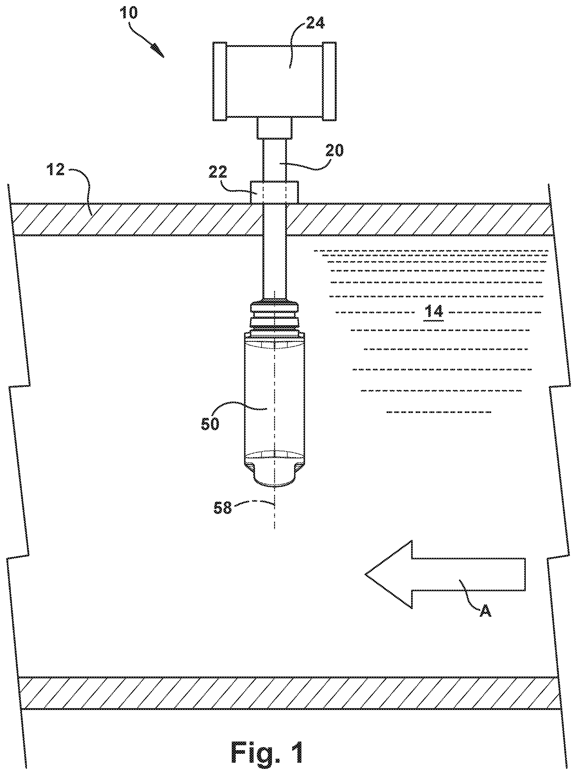
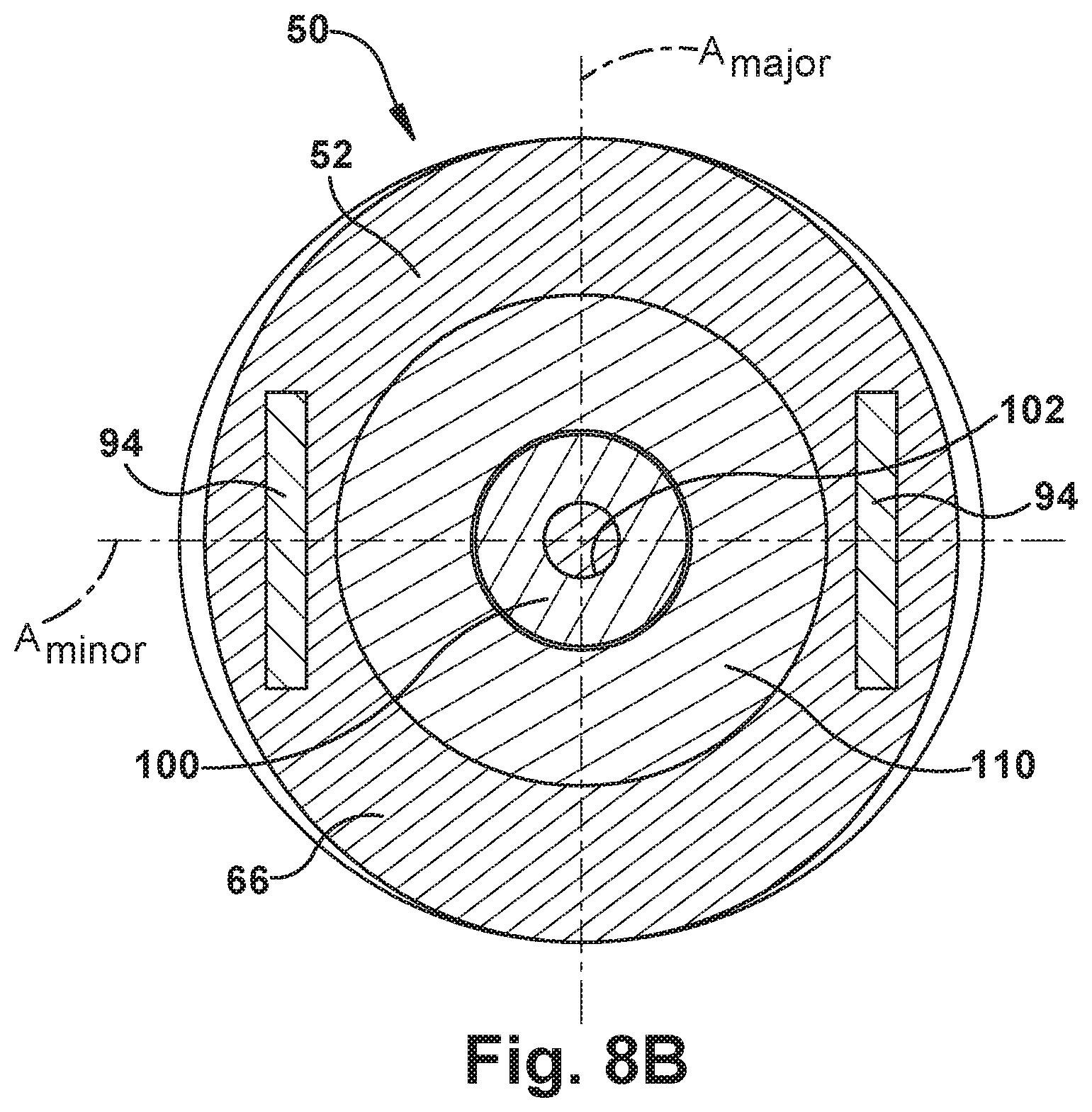
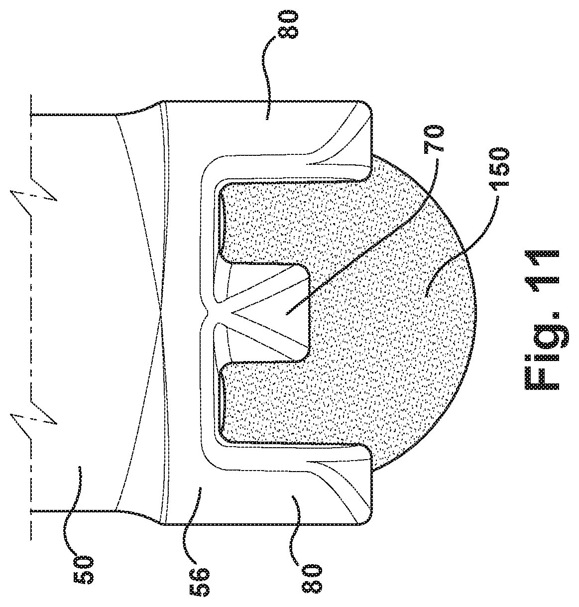
3. The apparatus recited in claim 1, wherein the body comprises a central fin positioned between laterally spaced first and second wings on a distal end of the body, wherein a first channel is defined between the first wing and a first side of the fin, wherein a second channel is defined between the second wing and a second side of the fin, wherein the first electrode is positioned in the first channel, and wherein the second electrode is positioned in the second channel.
4. The apparatus recited in claim 3, wherein the first wing comprises a convex surface presented inward toward the first channel, and the second wing comprises a convex surface presented inward toward the second channel.
5. The apparatus recited in claim 4, wherein the first and second sides of the fin comprise convex surfaces presented inward toward the first and second channels, respectively.
6. The apparatus recited in claim 3, wherein the core is ferromagnetic, extends between and axially beyond the electrodes, and has a terminal end portion positioned in the fin.
7. The apparatus recited in claim 3, further comprising a ferromagnetic frame comprising first and second legs that extend axially along the body on opposite sides of the coil, wherein the first and second legs extend axially beyond the electrodes, wherein the first leg has an end portion positioned in the first wing portion, and wherein the second leg has an end portion positioned in the second wing portion.
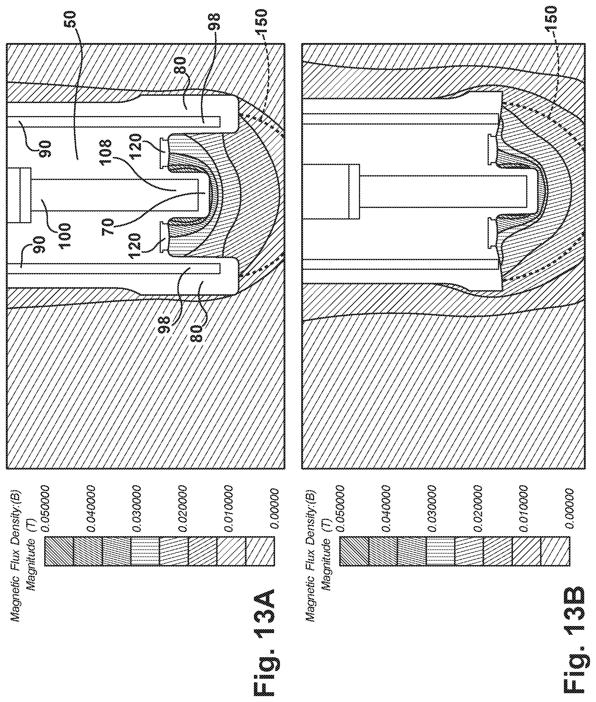
8. The apparatus recited in claim 7, wherein the end portions of the legs are configured to increase the flux density of the magnetic field in the channels.
9. The apparatus recited in claim 7, wherein the end portions of the legs are configured to increase the flux density of the magnetic field in an effective area of the sensor head.
10. The apparatus recited in claim 1, wherein the body is elongated and is configured to be inserted lengthwise into the conduit perpendicular to a fluid flow direction in the conduit, and wherein the at least one channel and the electrodes are disposed at a distal end of the body.
11. The apparatus recited in claim 10, wherein the body is configured to position the electrodes at equal insertion depths in the conduit, wherein the body is configured to align the electrodes with each other along an axis that is perpendicular to the fluid flow direction in the conduit, and wherein the body is configured to align the at least one channel parallel to the fluid flow direction in the conduit.
12. The apparatus recited in claim 1, wherein the converging sidewalls of the at least one channel are configured to reduce the cross-sectional area of the at least one channel in order to increase the flow velocity of the electrically conductive fluid flowing through the at least one channel.
13. The apparatus recited in claim 1, wherein the first electrode is positioned in a first channel and the second electrode is positioned in a second channel.
14. The apparatus recited in claim 13, wherein the body is elongated, cyl
D00000
D00001
D00002
D00003
D00004
D00005
D00006
D00007
D00008
D00009
D00010
D00011
D00012
D00013

XML
uspto.report is an independent third-party trademark research tool that is not affiliated, endorsed, or sponsored by the United States Patent and Trademark Office (USPTO) or any other governmental organization. The information provided by uspto.report is based on publicly available data at the time of writing and is intended for informational purposes only.
While we strive to provide accurate and up-to-date information, we do not guarantee the accuracy, completeness, reliability, or suitability of the information displayed on this site. The use of this site is at your own risk. Any reliance you place on such information is therefore strictly at your own risk.
All official trademark data, including owner information, should be verified by visiting the official USPTO website at www.uspto.gov. This site is not intended to replace professional legal advice and should not be used as a substitute for consulting with a legal professional who is knowledgeable about trademark law.