Device For Article Storage
Coats; James
U.S. patent application number 16/732526 was filed with the patent office on 2020-07-09 for device for article storage. This patent application is currently assigned to Tactical Medical Solutions, LLC. The applicant listed for this patent is Tactical Medical Solutions, LLC. Invention is credited to James Coats.
| Application Number | 20200217620 16/732526 |
| Document ID | / |
| Family ID | 71405055 |
| Filed Date | 2020-07-09 |


| United States Patent Application | 20200217620 |
| Kind Code | A1 |
| Coats; James | July 9, 2020 |
DEVICE FOR ARTICLE STORAGE
Abstract
A device for storing emergency-use articles on a safety vest or similar garment in a manner that presents the articles for easy access and use. A harness including multiple flexible strap arms is securable, using hook-and-loop material, to both front and back surfaces of a chest panel of a conventional safety vest. Storage tubes of flexible material are captured by threading one respective strap arm through each tube. The tubes are sized to retain within them an emergency-use article such as a tourniquet.
| Inventors: | Coats; James; (Gainesville, FL) | ||||||||||
| Applicant: |
|
||||||||||
|---|---|---|---|---|---|---|---|---|---|---|---|
| Assignee: | Tactical Medical Solutions,
LLC Anderson SC |
||||||||||
| Family ID: | 71405055 | ||||||||||
| Appl. No.: | 16/732526 | ||||||||||
| Filed: | January 2, 2020 |
Related U.S. Patent Documents
| Application Number | Filing Date | Patent Number | ||
|---|---|---|---|---|
| 62788192 | Jan 4, 2019 | |||
| Current U.S. Class: | 1/1 |
| Current CPC Class: | F41H 1/02 20130101; A41D 13/0007 20130101 |
| International Class: | F41H 1/02 20060101 F41H001/02; A41D 13/00 20060101 A41D013/00 |
Claims
1. A harness comprising: a stabilizing segment; a full harness arm segment; a first and second partitioned arm segment of the full harness arm segment formed by the bisection of the full harness arm segment with the stabilizing segment; and a first and second tube respectively connected to the first and second petitioned arm segment, each of the first and second tube having a diameter respectively corresponding to a width of the first and second petitioned arm segment, wherein the first partitioned arm segment is threaded through the first tube and the second partitioned arm segment is threaded through the second tube.
2. The harness of claim 1, wherein each tube includes a dispensing device secured at one end of the respective tube and having a length which is longer than the length of the respective tube such that a portion of each dispensing device extends from the respective tube.
3. The harness of claim 2, wherein the harness further includes an article maintained within the first or second tube by the dispensing device.
4. The harness of claim 3, wherein the article is a tourniquet.
5. The harness of claim 3, wherein the dispensing device of the tube having the article is configured to displace the article via the portion of the dispensing device extending from the tube.
6. The harness of claim 1, wherein the full arm segment has a width of 1.5 inches and a length of 18-20 inches, and the stabilizing segment has a length of 12-18 inches.
7. The harness of claim 1, wherein each tube is configured to slide to different positions along a length of a respective petitioned arm segment.
8. A vest comprising: a front panel; and a harness including a stabilizing segment; a full harness arm segment; a first and second partitioned arm segment of the full harness arm segment formed by the bisection of the full harness arm segment with the stabilizing segment; and a first and second tube respectively connected to the first and second petitioned arm segment, each of the first and second tube having a diameter respectively corresponding to a width of the first and second petitioned arm segment, wherein the first partitioned arm segment is threaded through the first tube and the second partitioned arm segment is threaded through the second tube, wherein the harness is affixed to an upper portion of the front panel via horizontally connected first and second portioned arm segments folded around the front panel and vertically connected stabilizing segment folded around the front panel and over the first and second portioned arm segments.
9. The vest of claim 8, wherein each tube includes a dispensing device secured at one end of the respective tube and having a length which is longer than the length of the respective tube such that a portion of each dispensing device extends from the respective tube.
10. The vest of claim 8, wherein the harness further includes an article maintained within the first or second tube by the dispensing device.
11. The vest of claim 10, wherein the article is a tourniquet.
12. The vest of claim 10, wherein the dispensing device of the tube having the article is configured to displace the article via the portion of the dispensing device extending from the tube.
13. The vest of claim 8, wherein the full arm segment has a width of 1.5 inches and a length of 18-20 inches, and the stabilizing segment has a length of 12-18 inches.
14. The vest of claim 8, wherein each tube is configured to slide to different positions along a length of a respective petitioned arm segment.
15. The vest of claim 8, wherein the vest is a ballistic weapon safety vest.
16. A harness comprising: a stabilizing segment; a full harness arm segment; a first and second partitioned arm segment of the full harness arm segment formed by the bisection of the full harness arm segment with the stabilizing segment; and a first and second tube respectively connected to the first and second petitioned arm segment, each of the first and second tube having a diameter respectively corresponding to a width of the first and second petitioned arm segment, wherein the first partitioned arm segment is threaded through the first tube and the second partitioned arm segment is threaded through the second tube, each tube includes a dispensing device secured at one end of the respective tube and having a length which is longer than the length of the respective tube, the harness further includes an article maintained within the first or second tube by the dispensing device, the article is a tourniquet, the dispensing device of the tube having the article is configured to displace the article via the portion of the dispensing device extending from the tube, each tube is configured to slide to different positions along a length of a respective petitioned arm segment.
17. The harness of claim 16, wherein the full arm segment has a width of 1.5 inches and a length of 18-20 inches, and the stabilizing segment has a length of 12-18 inches.
Description
FIELD OF THE INVENTION
[0001] The present invention relates to a buckle assembly having a strap and a slide buckle adapted to facilitate strap take-up and prevent strap slippage. The invention relates to devices for storing articles commonly used in emergency circumstances, where quick and nearby access to the articles is required.
BACKGROUND
[0002] An example article is a conventional tourniquet used by emergency services personnel who may respond to auto accidents or similar events where traumatic injuries to other persons may require immediate action. In such circumstances, for example, a tourniquet is most effectively used if available immediately to the responding personnel, without the need to leave the location of the injury. Most effectively, the tourniquet is on the body or garment of the emergency personnel.
SUMMARY OF THE INVENTION
[0003] The invention pertains to devices and methods for transporting such articles on the clothing or service garments of the personnel.
[0004] It is an object of the invention to provide such transportation in a non-cumbersome fashion on a garment of a user.
[0005] It is an object of the invention to provide for easy access to such articles to quickly provide life-saving activities and responding to injuries.
[0006] The foregoing and other objects of the present invention can be achieved by providing a harness having a stabilizing segment, a full harness arm segment, a first and second partitioned arm segment of the full harness arm segment formed by the bisection of the full harness arm segment with the stabilizing segment, and a first and second tube respectively connected to the first and second petitioned arm segment, each of the first and second tube having a diameter respectively corresponding to a width of the first and second petitioned arm segment. The first partitioned arm segment is threaded through the first tube and the second partitioned arm segment is threaded through the second tube.
[0007] The foregoing and other objects of the present invention can further be achieved by a vest having a front panel; and a harness including a stabilizing segment, a full harness arm segment, a first and second partitioned arm segment of the full harness arm segment formed by the bisection of the full harness arm segment with the stabilizing segment, and a first and second tube respectively connected to the first and second petitioned arm segment, each of the first and second tube having a diameter respectively corresponding to a width of the first and second petitioned arm segment. The first partitioned arm segment is threaded through the first tube and the second partitioned arm segment is threaded through the second tube. The harness is affixed to an upper portion of the front panel via horizontally connected first and second portioned arm segments folded around the front panel and vertically connected stabilizing segment folded around the front panel and over the first and second portioned arm segment.
[0008] The foregoing and other objects of the present invention can be further achieved by a harness having a stabilizing segment, a full harness arm segment, a first and second partitioned arm segment of the full harness arm segment formed by the bisection of the full harness arm segment with the stabilizing segment, and a first and second tube respectively connected to the first and second petitioned arm segment, each of the first and second tube having a diameter respectively corresponding to a width of the first and second petitioned arm segment. The first partitioned arm segment is threaded through the first tube and the second partitioned arm segment is threaded through the second tube. Each tube includes a dispensing device secured at one end of the respective tube and having a length which is longer than the length of the respective tube. The harness further includes an article maintained within the first or second tube by the dispensing device, the article is a tourniquet, the dispensing device of the tube having the article is configured to displace the article via the portion of the dispensing device extending from the tube, each tube is configured to slide to different positions along a length of a respective petitioned arm segment.
DESCRIPTION OF THE DRAWINGS
[0009] FIG. 1 illustrates one configuration of the invention, shown separated into its component elements.
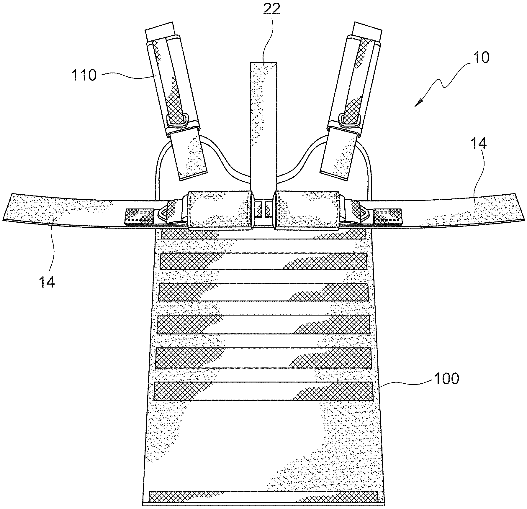
[0010] FIG. 2 illustrates the invention during assembling with a conventional safety vest.
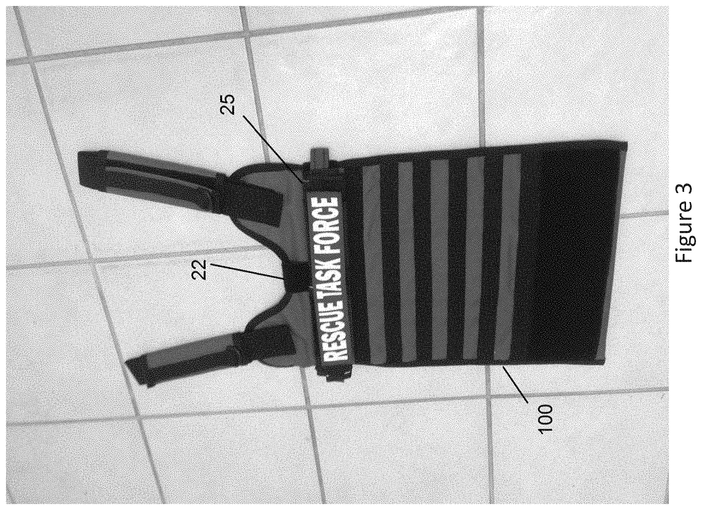
[0011] FIG. 3 illustrates the invention in condition for use combined with the front panel of a conventional safety vest.
DETAILED DESCRIPTION
[0012] FIG. 1 illustrates one configuration of the article storage invention, separated into component parts. The invention includes a harness 10 that is formed of flexible strapping such as woven nylon or polyester strap, preferably having a width of about 1.5 inches.
[0013] The harness 10 includes areas of hook-and-loop (HAL) attachment material secured in conventional manner in appropriate locations to the harness 10 to allow connection with the other elements of the invention as discussed in the following.
[0014] The harness 10 includes two harness arm portions 20, and a stabilizer portion 22 extending from the middle of the harness 10, between the two arm portions 20.
[0015] The length of the arm portions 20 and stabilizer 22 depends in part on the associated conventional garment to which the invention is intended to be secured in use. For many applications, the arm portions 20 may each have a length in the range of 18 to 20 inches, measured from the stabilizer to the distal end of the respective arm portion (total length of the contiguous arm portions is 36 to 40 inches). The stabilizer 22 may have a length of about 12 to 18 inches.
[0016] For discussion purposes, each arm portion 20 is divided into a front portion 12 and a more distal rear portion 14--the application of which is discussed below.
[0017] The purpose of the harness 10 is to provide a removeable base to which the needed article 99 may be removeable secured. The article 99 may be a folded conventional fabric tourniquet or other device as might be similarly needed by personnel in an emergency situation. The length and cross-section size of individual types of articles may differ--the dimensions of the invention here may be adjusted to accommodate the article as discussed.
[0018] The harness 10 must be adjustable in size and form to allow it to be adapted and secured to a variety of garments, such as for example different safety vests. As well, the harness 10 must be capable of storing and presenting the article 99 in a manner that is quickly and readily accessed by the emergency personnel wearing the associated garment.
[0019] The invention includes two storage tubes 25 formed of strong flexible fabric or similar material. The diameter of the tubes 25 is determined in part by the width of the arm portions 20 and the size of the article 99 to be stored. To secure the tubes 25 to the harness 10, one of each of the arm portions 20 is threaded through the opening of a respective tube 25.
[0020] Each tube 25 includes a dispensing device 27 to facilitate removal of the article 99 stored in a tube 25 at the time of use. In the present configuration, the dispensing device 27 comprises a length of narrow flexible fabric secured to one end of the tube 25. In use, when the article 99 is inserted into a tube 25, the dispensing device 27 is positioned against the entering end of the article 99 such that the dispensing device 27 enters with the article 99 and remains against the end of the article 99. The distal end of the dispensing device remains protruding from the tube 25 so as to be easily grasped by a user. By drawing on the distal end of the dispensing device 27, the article 99 may be removed (dispensed) from the tube 25 for use.
[0021] FIG. 1 includes two tubes 25. The left-most tube 25 is shown with a respective article 99 located within the tube 25 with only the distal end of the dispensing device 27 protruding. This is the normal stored condition of the device.
[0022] The size of the tube 25 is such that the length of the tube 25 is sufficient to securely capture and maintain the desired article 99 and the diameter of the tube 25 is such that the article 99 and the dispensing device may be inserted and maintained with sufficient tension to maintain the article 99 in place.
[0023] FIGS. 2 to 3 illustrate the invention as combined with a conventional ballistic weapon safety vest 100 as may be worn by emergency services personnel or police or military personnel.
[0024] In FIG. 2, the front panel of a conventional safety vest 100 is shown with the invention positioned in the normal relative location for use. The harness 10 is placed near the top of the vest 100 and centered between the vest shoulder straps 110. This location is not critical but is believed to be most convenient for use by most personnel. The stabilizer 22 and harness back portion 14 are shown extended from the vest and ready to be secured to the vest 100. The respective overlapping sides of the various portions of the harness preferably include HAL material to secure the harness 10 to the vest 100 and secure the harness portions to each other wherever they overlap.
[0025] To complete securing the invention to the vest 100, the stabilizer 22 is folded over the top edge of the vest 100 and then down to reside against the backside (not shown) of the vest 100. The two back portions 14 are then similarly folded to reside over the stabilizer 22 and against the vest backside. In the configuration shown, the tubes 25 and the stored articles 99 are positioned relatively high on the vest front surface (away from the user's active hands) yet within easy reach of the user.
[0026] FIG. 3 depicts a completed vest 100 front panel with the invention secured in place. An informational banner ("RESCUE TASK FORCE") has been attached, using HAL material, to the two tube 25.
[0027] In alternative configurations, the tubes 25 are positioned on the back portions 14 so that when assembled to a vest, the tubes 25 and respective stored article 99 are located on the back (inside) surface of the front vest panel--between the front vest panel and the user's body when worn.
[0028] The above description is that of current embodiments of the invention. Various alterations and changes can be made without departing from the spirit and broader aspects of the invention as defined in the appended claims, which are to be interpreted in accordance with the principles of patent law including the doctrine of equivalents. This disclosure is presented for illustrative purposes and should not be interpreted as an exhaustive description of all embodiments of the invention or to limit the scope of the claims to the specific elements illustrated or described in connection with these embodiments. For example, and without limitation, any individual element(s) of the described invention may be replaced by alternative elements that provide substantially similar functionality or otherwise provide adequate operation. This includes, for example, presently known alternative elements, such as those that might be currently known to one skilled in the art, and alternative elements that may be developed in the future, such as those that one skilled in the art might, upon development, recognize as an alternative. Further, the disclosed embodiments include a plurality of features that are described in concert and that might cooperatively provide a collection of benefits. The present invention is not limited to only those embodiments that include all of these features or that provide all of the stated benefits, except to the extent otherwise expressly set forth in the issued claims. Any reference to elements in the singular, for example, using the articles "a," "an," "the" or "said," is not to be construed as limiting the element to the singular.
* * * * *
D00000
D00001
D00002
D00003
XML
uspto.report is an independent third-party trademark research tool that is not affiliated, endorsed, or sponsored by the United States Patent and Trademark Office (USPTO) or any other governmental organization. The information provided by uspto.report is based on publicly available data at the time of writing and is intended for informational purposes only.
While we strive to provide accurate and up-to-date information, we do not guarantee the accuracy, completeness, reliability, or suitability of the information displayed on this site. The use of this site is at your own risk. Any reliance you place on such information is therefore strictly at your own risk.
All official trademark data, including owner information, should be verified by visiting the official USPTO website at www.uspto.gov. This site is not intended to replace professional legal advice and should not be used as a substitute for consulting with a legal professional who is knowledgeable about trademark law.