Electric Oil Pump Device
KATAOKA; Shigehiro ; et al.
U.S. patent application number 16/711475 was filed with the patent office on 2020-07-09 for electric oil pump device. The applicant listed for this patent is Nidec Tosok Corporation. Invention is credited to Shigehiro KATAOKA, Yoshiyuki KOBAYASHI.
| Application Number | 20200217309 16/711475 |
| Document ID | / |
| Family ID | 71405007 |
| Filed Date | 2020-07-09 |


| United States Patent Application | 20200217309 |
| Kind Code | A1 |
| KATAOKA; Shigehiro ; et al. | July 9, 2020 |
ELECTRIC OIL PUMP DEVICE
Abstract
A filter module includes an attachment attached to an attachment catch. The attachment of the filter module on the attachment catch of the electric oil pump main body to the attachment catch is fixed in a posture where an outlet port of the filter module is caused to communicate with the suction port of the electric oil pump main body.
| Inventors: | KATAOKA; Shigehiro; (Zama-shi, JP) ; KOBAYASHI; Yoshiyuki; (Zama-shi, JP) | ||||||||||
| Applicant: |
|
||||||||||
|---|---|---|---|---|---|---|---|---|---|---|---|
| Family ID: | 71405007 | ||||||||||
| Appl. No.: | 16/711475 | ||||||||||
| Filed: | December 12, 2019 |
| Current U.S. Class: | 1/1 |
| Current CPC Class: | F04B 17/03 20130101; F04B 53/20 20130101; F04B 15/02 20130101 |
| International Class: | F04B 17/03 20060101 F04B017/03; F04B 15/02 20060101 F04B015/02; F04B 53/20 20060101 F04B053/20 |
Foreign Application Data
| Date | Code | Application Number |
|---|---|---|
| Jan 7, 2019 | JP | 2019-000745 |
Claims
1. An electric oil pump device, comprising: an electric oil pump main body including a pump, a motor that drives the pump, a suction port that suctions oil, and an ejection port that ejects the oil; a filter module that includes an inlet port that receives the oil, an outlet port that discharges the oil passing through the inlet port, and an attachment that is attached to the electric oil pump main body; an attachment catch, which is provided on the electric oil pump main body, to which the attachment of the filter module is attached; and a fastener that secures, to the attachment catch, the attachment of the filter module placed on the attachment catch of the electric oil pump main body in a posture in which the outlet port is caused to communicate with the suction port of the electric oil pump main body.
2. The electric oil pump device according to claim 1, wherein the filter module includes a filter that filters the oil and an accommodation case that accommodates the filter; and the inlet port, the outlet port, and the attachment are provided on the accommodation case.
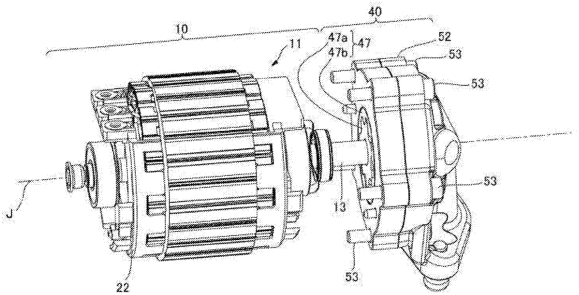
3. The electric oil pump device according to claim 2, wherein the suction port is directed in a direction around a central axial line of a motor shaft of the motor; the attachment includes a first attachment surface that is attached to a side of the pump and a second attachment surface that is attached to a side of the motor; and the filter module is secured to the electric oil pump main body such that the filter module opposes both the pump and the motor in an axial direction.
4. The electric oil pump device according to claim 3, wherein the suction port is closer to the motor than the ejection port in the axial direction; and the suction port and the ejection port are aligned along an axial line extending in the axial direction.
5. The electric oil pump device according to claim 3, wherein an inverter that controls driving of the motor is secured to an end surface of the motor on a side opposite to a side of the pump in the axial direction; a posture of the inverter secured to the end surface is a posture in which a longitudinal direction of the inverter follows the radial direction and an end portion of the inverter in the longitudinal direction projects beyond an end of the electric oil pump main body in a direction along the longitudinal direction of the inverter secured to the pump; and the filter module is in a region between the end of the electric oil pump main body and an end of the end portion of the inverter in the longitudinal direction.
6. The electric oil pump device according to claim 4, wherein an inverter that controls driving of the motor is secured to an end surface of the motor on a side opposite to a side of the pump in the axial direction; a posture of the inverter secured to the end surface is a posture in which a longitudinal direction of the inverter follows the radial direction and an end portion of the inverter in the longitudinal direction projects beyond an end of the electric oil pump main body in a direction along the longitudinal direction of the inverter secured to the pump; and the filter module is in a region between the end of the electric oil pump main body and an end of the end portion of the inverter in the longitudinal direction.
Description
CROSS REFERENCE TO RELATED APPLICATION
[0001] The present invention claims priority under 35 U.S.C. .sctn. 119 to Japanese Application No. 2019-000745 filed on Jan. 7, 2019, the entire contents of which are hereby incorporated by reference.
FIELD OF THE INVENTION
[0002] The present disclosure relates to an electric oil pump device.
BACKGROUND
[0003] In the related art, an electric oil pump that includes a pump portion, a motor portion that drives the pump portion, a suctioning port that suctions oil, and an ejection port that ejects the oil is known.
[0004] An electric oil pump disclosed in Japanese Patent Laid-Open No. 2017-002841, for example, includes a pump portion, a motor portion, and a suctioning port and an ejection port provided at the pump portion. The electric oil pump is mounted in an oil pan of a vehicle in the form in which the electric oil pump is dipped in the oil in the oil pan and suctions the oil directly with the suctioning port at on the pump portion into the pump portion. The oil in the pump portion is ejected from the ejection port and is then fed to a transmission or the like of the vehicle.
[0005] Meanwhile, a strainer is known as a filter module for removing impurities from the oil before being suctioned into an oil pump in the related art.
[0006] A strainer disclosed in Japanese Patent Laid-Open No. 2017-160955, for example, includes a case portion that accommodates a filtration material and a long and thin tubular portion that communicates with the case portion aid and is mounted in an oil pan in the a form in which the case portion is dipped in the oil in the oil pan. An end of the tubular portion is connected to an oil pump outside the oil pan. The oil suctioned from a suctioning hole at in the case portion into the case portion passes through the filtration material in the case portion and the tubular portion, then flows out of a flowing-out hole at in the tubular portion, and is suctioned into the oil pump.
[0007] According to the strainer disclosed in Japanese Patent Laid-Open No. 2017-160955, since it is necessary to align the strainer attached to the oil pan and with the suctioning port of the oil pump disposed outside the oil pan, and mountability of the oil pump and the strainer to the vehicle may be degraded. In a case in which the strainer is attached to the oil pan earlier than the strainer, for example, mountability of the oil pump may be degraded. In a case in which the alignment is not successfully performed when the oil pump is attached, a situation in which it is necessary to attach the strainer again is also conceivable. In a case in which the oil pump is attached to the outside of the oil pan earlier than the strainer, mountability of the strainer may be degraded. In a case in which the alignment is not successfully performed when the strainer is attached, a situation in which it is necessary to attach the oil pump again is also conceivable.
[0008] Also, the strainer disclosed in Japanese Patent Laid-Open No. 2017-160955 requires a space for disposing the long and thin tubular portion (pipe) to be provided inside the oil pan, and it is thus difficult to save a space for the oil pan and to reduce the weight of the oil pan. Further, the long and thin tubular portion applies a resistance to the oil flowing in the tubular portion in the strainer disclosed in Japanese Patent Laid-Open No. 2017-160955, and pump efficiency may thus be degraded.
[0009] As described above, the strainer disclosed in Japanese Patent Laid-Open No. 2017-160955 has problems that mountability of the oil pump and the strainer may be degraded, it may be difficult to save space and to reduce the weight of oil reservoir equipment, such as an oil pan, and pump efficiency may be degraded. Note that similar problems may occur even in a case in which the strainer disclosed in Japanese Patent Laid-Open No. 2017-160955 is connected to an electric oil pump that is not disposed outside the oil pan but is attached to the inside of the oil pan as in the case of the electric oil pump disclosed in Japanese Patent Laid-Open No. 2017-002841.
SUMMARY
[0010] Example embodiments of the present disclosure each provide an electric oil pump device capable of improving mountability of a filter module and an electric oil pump main body, saving a space and reducing the weight of oil reservoir equipment, and improving pump efficiency of the electric oil pump main body.
[0011] According to a first example embodiment of the present disclosure, an electric oil pump device includes an electric oil pump main body including a pump, a motor that drives the pump, a suction port that suctions oil, and an ejection port that ejects the oil. The electric oil pump device includes a filter module that includes an inlet port that receives the oil, an outlet port that discharges the oil passing through the inlet port, and an attachment that is attached to the electric oil pump main body, an attachment catch, which is provided at on the electric oil pump main body, to which the attachment of the filter module is attached, and a fastener that secures, to the attachment catch, the attachment of the filter module on the attachment catch of the electric oil pump main body in a posture in which the outlet port is caused to communicate with the suction port of the electric oil pump main body.
[0012] According to the exemplary first disclosure of the present disclosure, excellent effects of improving mountability of the filter module and the electric oil pump main body, to save space and reduce the weight of the oil reservoir equipment, and to improve pump efficiency of the electric oil pump main body are achieved.
[0013] The above and other elements, features, steps, characteristics and advantages of the present disclosure will become more apparent from the following detailed description of the example embodiments with reference to the attached drawings.
BRIEF DESCRIPTION OF THE DRAWINGS
[0014] FIG. 1 is a perspective view illustrating an electric oil pump device according to an example embodiment of the present disclosure.
[0015] FIG. 2 is an exploded perspective view illustrating a motor accommodated inside a housing of the electric oil pump device, a pump cover of a pump, and the respective members in the pump cover according to an example embodiment of the present disclosure.
[0016] FIG. 3 is an exploded perspective view illustrating the electric oil pump device from the -Z side.
[0017] FIG. 4 is a cut away perspective view illustrating a strainer according to an example embodiment of the present disclosure in a partially cut away state.
[0018] FIG. 5 is a plan view illustrating an electric oil pump device according to a first example embodiment of the present disclosure from the -Z side in the Z-axis direction in a state in which an external pipe and a filter module have been removed therefrom.
[0019] FIG. 6 is a plan view illustrating the electric oil pump device according to the first example embodiment from the -Z side in the Z-axis direction in a state in which the external pipe and the filter module have been attached thereto.
[0020] FIG. 7 is an exploded side view illustrating an electric oil pump device according to a second example embodiment of the present disclosure from the +Y side.
[0021] FIG. 8 is a perspective view illustrating a filter module of an electric oil pump device according to a third example embodiment of the present disclosure.
DETAILED DESCRIPTION
[0022] Hereinafter, electric oil pump devices according to example embodiments of the present disclosure will be described with reference to drawings. In the example embodiments, an electric oil pump device that supplies oil to a transmission mounted in a vehicle, such as a car, will be described. Also, sizes, numbers, and the like of the respective structures in the following drawings may be different from those of actual structures for ease of understanding of the respective constituents.
[0023] Also, an XYZ coordinate system will appropriately be illustrated as a three-dimensional orthogonal coordinate system in the drawings. In the XYZ coordinate system, the X-axis direction is defined as a direction that is parallel to an axial direction of a central axis J illustrated in FIG. 1. The central axis J is a central axial line of a shaft (motor shaft) 13 of a motor portion 10, which will be described later. The Z-axis direction is defined as a direction that is parallel to a central axial line of a suctioning portion (which will be described later) of the motor portion 10. The Y-axis direction is defined as a direction that perpendicularly intersects both the X-axis direction and the Z-axis direction. In each of the X-axis direction, the Y-axis direction, and the Z-axis direction, the side to which the arrow is directed in the drawing is defined as a +side while the opposite side is defined as a -side.
[0024] Also, the positive side (+X side) in the X-axis direction will be referred to as a "rear side" while the negative side (-X side) in the X-axis direction will be referred to as a "front side" in the following description. Note that the rear side and the front side are names used only for explanation and do not limit actual positional relationships and directions. Also, the direction (X-axis direction) that is parallel to the central axis J will simply be referred to as an "axial direction, the radial direction around the central axis J will simply be referred to as a "radial direction", and the circumferential direction around the central axis J, that is, the circumferential direction (.theta. direction) around the central axis J will simply be referred to as a "circumferential direction".
[0025] Note that in the specification, extending in the axial direction also includes a case of extending in a direction inclined within a range of less than 45.degree. with respect to the axial direction in addition to a case of extending strictly in the axial direction (X-axis direction). Also, extending in the radial direction in the specification also includes a case of extending in a direction inclined within a range of less than 45.degree. with respect to the radial direction in addition to a case of extending strictly in the radial direction, that is, in the direction that is perpendicular to the axial direction (X-axis direction).
EXAMPLE EMBODIMENTS
<Overall Configuration>
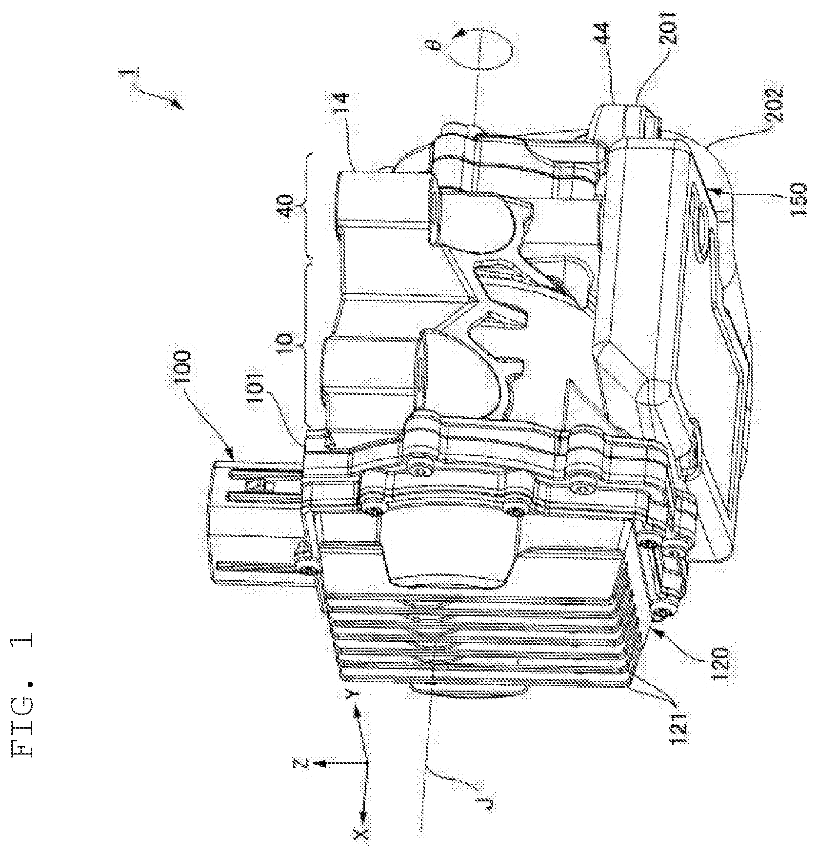
[0026] FIG. 1 is a perspective view illustrating an electric oil pump device 1 according to an example embodiment. The electric oil pump device 1 according to the example embodiment includes an electric oil pump main body that has a motor portion 10, a housing 14, a pump portion 40, an inverter 100, and a heatsink 120 as illustrated in FIG. 1. Also, the electric oil pump device 1 includes a filter module 150. The motor portion 10 includes a shaft (which will be described later) disposed along the central axis J extending in the axial direction.
[0027] The pump portion 40 is located on one side (front side) of the motor portion 10 in the axial direction and is driven by the motor portion 10 via a shaft 13 to eject oil. The inverter 100 is disposed on the rear side of the motor portion 10 and controls driving of the motor portion 10.
[0028] The heatsink 120 is secured to an end surface of a case 101 of the inverter 100 on the rear side in the axial direction and cools the inverter 100 by discharging heat generated by an operation thereof and delivered from the inverter 100. The heatsink 120 includes a plurality of fins 121 extending in the Z-axis direction in order to efficiently perform the aforementioned heat discharge.
[0029] The housing 14 serves both as a housing of the motor portion 10 and a housing of the pump portion 40 and includes a partition wall that partitions the motor portion 10 from the pump portion 40. The housing 14 is made of a cast article made of metal (aluminum, for example).
[0030] In the electric oil pump device 1 according to the example embodiment, the housing of the motor portion 10 and the housing of the pump portion 40 that are formed by the housing 14 are parts of a single member. With such a configuration, a boundary between the housing of the motor portion 10 and the housing of the pump portion 40 in the axial direction is defined as follows. That is, the center of the partition wall that partitions the motor portion 10 and the pump portion 40 in the axial direction is a boundary between the motor portion 10 and the pump portion 40 in the axial direction.
<Motor Portion 10>
[0031] FIG. 2 is an exploded perspective view illustrating the motor 11 accommodated inside the housing (14 in FIG. 1), a pump cover 52 of the pump portion 40, and the respective members in the pump cover 52. The motor portion 10 includes the motor 11 as illustrated in FIG. 2. The motor 11 is an inner rotor-type motor, for example, and includes the shaft 13 as a motor shaft and a cylindrical stator 22.
[0032] Inside the stator 22 in the radial direction, a rotor which is not illustrated in FIG. 2 is secured to an outer circumferential surface of the shaft 13, and an outer circumferential surface of the rotor faces an inner circumferential surface of the stator 22 with a predetermined gap therebetween. The rotor is secured to the shaft 13 on the rear side in the axial direction.
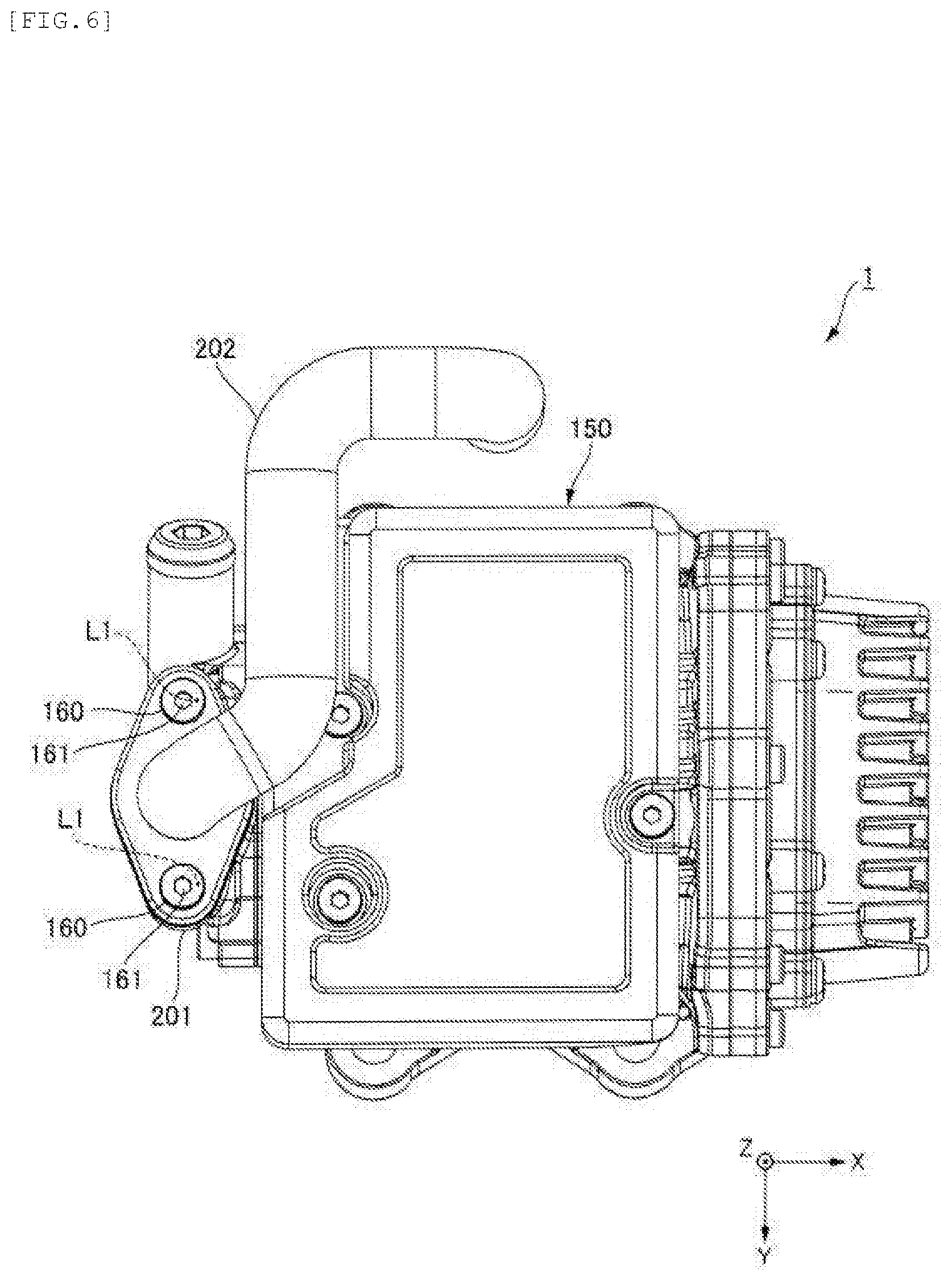
[0033] The shaft 13 penetrates through a through-hole provided in the partition wall of the housing (14 in FIG. 1) that partitions the motor portion 10 and the pump portion 40 and enters the pump portion 40 from the motor portion 10.
<Pump Portion 40>
[0034] The pump portion 40 includes a pump rotor 47 and a pump cover 52.
(Pump Rotor 47)
[0035] The pump rotor 47 is attached to an end portion of the shaft 13 on the front side. The pump rotor 47 includes an inner rotor 47a and an outer rotor 47b. The inner rotor 47a is secured to the shaft 13. The outer rotor 47b surrounds the outside of the inner rotor 47a in the radial direction.
[0036] The inner rotor 47a has an annular shape. The inner rotor 47a is a gear that has teeth on an outer surface thereof in the radial direction. The inner rotor 47a rotates about the axis (the .theta. direction in FIG. 1) along with the shaft 13. The outer rotor 47b has an annular shape surrounding the outside of the inner rotor 47a in the radial direction. The outer rotor 47b is a gear that has teeth on an inner surface thereof in the radial direction. An outer surface of the outer rotor 47b in the radial direction has a circular shape.
[0037] The gear on the outer surface of the inner rotor 47a in the radial direction and the gear of the inner surface of the outer rotor 47b in the radial direction engage with each other, and the outer rotor 47b rotates by the inner rotor 47a rotating with rotation of the shaft 13. That is, the pump rotor 47 rotates due to rotation of the shaft 13.
[0038] Due to the inner rotor 47a and the outer rotor 47b rotating, a volume in the engagement portion between the inner rotor 47a and the outer rotor 47b changes. A region in which the volume decreases is a pressurization region, and a region in which the volume increases is a negative pressure region.
(Pump Cover 52)
[0039] The housing 14 illustrated in FIG. 1 includes an opening at an end on the front side in the axial direction. The opening is closed with the pump cover 52 illustrated in FIG. 2. The pump cover 52 is secured to the housing 14 with a bolt 53.
[0040] The pump cover 52 accommodates the pump rotor 47 that includes the inner rotor 47a secured to the shaft 13 and the outer rotor 47b that is engaged with the inner rotor 47a.
[0041] The rotor accommodation portion that accommodates the pump rotor 47 of the pump portion 40 and the motor accommodation portion of the motor portion 10 may be parts of a single member or may be separate elements. Also, the housing of the motor portion 10 and the housing of the pump portion 40 may be separate elements.
<Inverter 100>
[0042] The inverter 100 illustrated in FIG. 1 includes an electronic substrate in the case 101. The electronic substrate includes a plurality of electronic components and a substrate with the plurality of electronic components mounted thereon. On the substrate, a plurality of bipolar transistors (MOS-FET) as switching elements are mounted. Since the plurality of bipolar transistors generate a large amount of heat with driving, the temperature of the entire inverter 100 is raised. One of roles of the heatsink 120 is to discharge heat delivered from the inverter 100, the temperature of which has been raised due to the heat generated by the bipolar transistors.
<Filter Module 150>
[0043] In FIG. 1, the filter module 150 is secured to an end surface of the housing 14 on the -Z side in the Z-axis direction. The filter module 150 plays a role of filtering oil before being suctioned by the suctioning port, which will be described later, of the pump portion 40.
[0044] FIG. 3 is an exploded perspective view illustrating the electric oil pump device 1 from the -Z side. The housing 14 is a part of the electric oil pump main body provided with the motor portion 10, the pump portion 40, and the like. The suctioning port 41 through which the oil is suctioned into the pump portion 40 is provided in a region that serves as the housing of the pump portion 40 in the entire region of the housing 14 in the axial direction. The suctioning-side flange 43 is provided at an end portion of the region on the -Z side in the Z-axis direction, and the suctioning port 41 is provided in the suctioning-side flange 43.
[0045] Note that FIGS. 1 and 3 illustrate a state in which an external flange 201 has been attached to an ejection-side flange 44 of the electric oil pump device 1 and an external pipe 202 has been connected to the external flange 201.
[0046] The respective components of the electric oil pump device 1 are designed on the assumption that the electric oil pump device 1 is placed in an oil pan of a transmission or the like in a posture in which the suctioning port 41 is directed downward in the direction of gravity. In the electric oil pump device 1 in the aforementioned posture, the filter module 150 is located lower down in the gravity direction.
[0047] The ejection-side flange 44 is provided on an end portion of the pump cover 52 on the -Z side in the Z-axis direction. The ejection port 42 that ejects the oil in the pump portion 40 is provided in the ejection-side flange 44. The external flange 201 is connected to the ejection-side flange 44, and the external pipe 202 is connected to the external flange 201. The oil discharged from the ejection port 42 of the pump portion 40 is fed to the transmission and the like of the vehicle via the external flange 201 and the external pipe 202. The suctioning port 41 is provided so as to be closer to the side of the motor portion 10 than the ejection port 42 is in the axial direction.
[0048] The base 14a projecting from the circumferential surface of the housing 14 on the -Z side is provided on an end portion of the housing 14 on the rear side in the axial direction that is an end on the -Z side in the Z-axial direction. The base 14a is a part of the motor portion 10.
[0049] The filter module 150 is attached to the suctioning-side flange 43 and the base 14a. That is, the suctioning-side flange 43 and the base 14a function as an attachment catching portion.
[0050] An end surface (43a) of the suctioning-side flange 43 on the -Z side in the Z-axis direction and an end surface (14a1) of the base 14a on the -Z axis side in the Z-axis direction are attachment catching surfaces to which the filter module 150 is attached. Hereinafter, the former end surface and the latter end surface will be referred to as an attachment catching surface 43a and an attachment catching surface 14a1, respectively.
[0051] The filter module 150 includes an accommodation case 151 that has a plane extending in the axial direction and the Y-axis direction as an outer surface and has a flattened shape with a dimension thinned in the Z-axis direction. An inlet port opening 151a is provided in an end surface of the accommodation case 151 on the -Z side in the Z-axis direction. The inlet port opening 151a functions as an inlet port of the filter module 150.
[0052] The electric oil pump device 1 is placed in the oil pan of the transmission in a posture in which the suctioning port 41 is directed downward in the gravity direction, and then in the oil pan, the filter module 150 of the electric oil pump device 1 is dipped in the oil stored in the oil pan. The inlet port opening 151a of the filter module 150 is directed outward in the radial direction and faces a bottom surface of the oil pan in the oil pan. Therefore, impurities that have sunk to the bottom of the oil pan are efficiently suctioned into the filter module 150 through the inlet port opening 151a.
[0053] FIG. 4 is a cut away perspective view illustrating the filter module 150 in a partially cut away state. The cut surface of the filter module 150 illustrated in the drawing extends in the X-Z-axis direction at an end portion of the filter module 150 on the +Y side in the Y-axis direction.
[0054] A flange portion 151b projecting on the +Z side from an end surface of the filter module 150 on the +Z side in the Z-axis direction is provided on the end surface. A surface of the flange portion 151b on the +Z side is an attachment surface 151b1 that is attached to the attachment catching surface 43a of the suctioning-side flange 43 on the pump portion 40 illustrated in FIG. 3. The attachment surface 151b1 of the filter module 150 illustrated in FIG. 4 is provided with an outlet port 151, two through-holes 151d, an O ring 165, and an O ring groove 166. The O ring 165 is inserted into the O ring groove 166 surrounding the circumference of the outlet port 151c and projects on the +Z side beyond the attachment surface 151b1. The O ring 165 seals a gap between the attachment surface 151b and the attachment catching surface 43a of the suctioning-side flange 43 and prevents entry of oil, which has not been filtered, to the gap therebetween.
[0055] A base insertion portion 151f is provided on an end portion of the accommodation case 151 on the +X side in the axial direction. The base insertion portion 151f functions as an attachment portion that is attached to the base (14a in FIG. 3) of the housing and includes a through-hole 151f1 and an attachment surface 151f2. The attachment surface 151f2 extends in the X-Y-axis direction. Although the through-hole 151f1 is provided in the attachment surface 151f2 and penetrates through the accommodation case 151 in the Z-axis direction, the through-hole 151f1 does not communicate with the inside of the accommodation case 151 since the through-hole 151f1 includes a tubular circumferential wall. The attachment surface 151f2 of the base insertion portion 151f is attached to the attachment catching surface 14a1 of the base 14a on the motor portion 10 illustrated in FIG. 3 in a close contact state.
[0056] In FIG. 3, two bolts 45 projecting toward the -Z side are provided on the attachment catching surface 43a of the suctioning-side flange 43 on the pump portion 40. The two bolts are caused to pass through the through-holes 151d in the accommodation case 151 of the filter module 150.
[0057] A bolt 15 projecting toward the -Z side is provided in the attachment catching surface 14a1 of the base 14a. The bolt 15 is caused to pass through the through-hole 151f1 of the base insertion portion 151f at the filter module 150.
[0058] The bolts 45 caused to pass through the two through-holes 151d in the accommodation case of the filter module 150 and the bolt 15 caused to pass through the through-hole 151f1 of the base insertion portion 151f are fastened with nuts 160. The filter module 150 is secured to the motor portion 10 and the pump portion 40 through the fastening. The thus secured filter module 150 causes the outlet port 151c provided in the attachment surface 151b to communicate with the suctioning port 41 provided at the suctioning-side flange 43 illustrated in FIG. 3. The bolts 45, the bolt 15, and the nuts 160 function as secure members as follows. That is, the bolts 45, the bolt 15, and the nuts 160 are securing fasteners that secure the base insertion portion 151f and the flange portion 151b of the filter module 150 to the base 14a and the suctioning-side flange 43 in a posture in which the outlet port 151c of the filter module 150 is caused to communicate with the suctioning port 41 of the electric oil pump main body.
[0059] The securing fasteners are not limited to the bolts and the nuts. For example, a combination of female screw holes and male screws may also be employed. Alternatively, rivets, caulking members, welded members, or the like may also be employed.
[0060] The filter module 150 secured to the electric oil pump main body causes an internal space of the accommodation case 151 and the suctioning port 41 provided at the suctioning-side flange 43 illustrated in FIG. 3 to communicate with each other. The two through-holes 151d of the filter module 150 illustrated in FIG. 4 penetrate from the end surface of the accommodation case 151 on the +Z side to the end surface thereof on the -Z side in the Z-axis direction. The two through-holes 151d include tubular circumferential walls and thus do not communicate with the inside of the accommodation case 151.
[0061] The filter module 150 secured to the motor portion 10 and the pump portion 40 of the electric oil pump main body covers the suctioning port 41 provided at the pump portion 40. If a suctioning force is generated at the suctioning port 41, then the pressure in the internal space of the accommodation case 151 that communicates with the suctioning port 41 via the outlet port (151c in FIG. 4) of the accommodation case 151 of the filter module 150 becomes a negative pressure. Due to the negative pressure, a suctioning force is generated in the inlet port opening 151a of the accommodation case 151. Due to the suctioning force, the oil flows into the internal space of the accommodation case 151 through the inlet port opening 151a.
[0062] As illustrated in FIG. 4, the oil filter 153 with a volume with which the internal space of the accommodation case 151 is substantially filled is accommodated in the accommodation case 151 of the filter module 150. The oil filter 153 filters the oil with a finer mesh than a metal mesh that is typically used to remove impurities. The oil filter 153 is made of a filter material such as a filter paper folded in a accordion shape, a non-woven cloth, or synthetic fiber solidified in a sponge form, or the like.
[0063] Unlike the electric oil pump device 1 according to the example embodiment, it is necessary to use a member made of metal with high rigidity, such as a metal mesh, as a filter material in the configuration in which the suctioning port 41 is covered with the filter material attached directly to the suctioning-side flange 43 illustrated in FIG. 3. Since the fineness of the mesh of the filter material made of metal is limited due to a difficulty in metal working, it is difficult to remove fine impurities such as metal powder. Meanwhile, in the module provided with the accommodation case 151 for accommodating the oil filter 153 as a filter material as in the electric oil pump device 1 according to the example embodiment, it is possible to use a filter material with a fine mesh made of a filter paper, a non-woven cloth, a synthetic fiber, or the like. Accordingly, it is possible to satisfactorily remove fine impurities such as metal powder from the oil according to the electric oil pump device 1.
[0064] The oil that has flow into the internal space of the accommodation case 151 moves from the -Z side to the +Z side in the Z-axis direction due to the suctioning force generated by the suctioning port 41 of the pump portion 40 illustrated in FIG. 3. By the oil passing through the oil filter 153 illustrated in FIG. 4 in the process of the movement, particles that are finer than the mesh of a screen 152 are removed from the oil. The oil, from which the fine impurities have been removed, is suctioned into the pump portion 40 via the outlet port 151c of the accommodation case 151 and the suctioning port 41 of the pump portion 40 illustrated in FIG. 3.
[0065] A surface of the accommodation case 151, in which the inlet port opening 151a is provided, extends in the X-Y plane direction. In the plane, an opening area of the inlet port opening 151a is larger than an area of a portion except for the inlet port opening 151a. With such a configuration, the oil moves to the +Z side along the Z-axis direction while satisfactorily spreading in the X-Y plane direction in the oil filter 153. Therefore, it is possible to curb a decrease in lifetime of the oil filter 153 due to acceleration of clogging of a specific region as compared with clogging of the other regions caused because of the passing oil concentrating on the specific region in the X-Y plane direction of the oil filter 153.
<Effects and Advantages of Electric Oil Pump Device 1>
[0066] (1) The electric oil pump device 1 includes the filter module 150 including the inlet port opening 151a that serves as an inlet port for receiving oil, an outlet port 151c that discharges the oil passing through the inlet port opening 151a, and a flange portion 151b and the base insertion portion 151f that serve as an attachment portion. Also, the electric oil pump device 1 includes the suctioning-side flange 43 and the base 14a that serve as an attachment catching portion, which is provided at the electric oil pump main body (including the motor portion 10, the pump portion 40, and the like), to which the flange portion 151b and the base insertion portion 151f of the filter module 150 are attached. Further, the electric oil pump device 1 includes the bolt 15, the bolts 45, and the nuts 160 as securing fasteners. The securing fasteners secure the flange portion 151b and the base insertion portion 151f of the filter module 150 placed on the electric oil pump main body to the suctioning-side flange 43 and the base 14a in a posture in which the outlet port 151c is caused to communicate with the suctioning port 41.
[0067] In the electric oil pump device 1 with such a configuration, it is not necessary to secure a long and thin tubular installation space inside the oil pan since the filter module 150 is attached directly to the electric oil pump main body without the long and thin tubular portion (pipe) being interposed therebetween. Accordingly, it is possible to save space and to reduce the weight of the oil pan. Further, it is also possible to reduce the number of components and to reduce costs corresponding to the unnecessary long and thin tubular portion.
[0068] Also, since it is possible to attach the electric oil pump device 1 in a state in which the filter module 150 is attached to the electric oil pump main body to the oil pan according to the electric oil pump device 1, it is not necessary to align the suctioning port 41 of the electric oil pump main body and the outlet port 151c of the filter module 150 in the oil pan. Therefore, it is possible to improve mountability of the filter module 150 and the electric oil pump main body to the oil pan according to the electric oil pump device 1.
[0069] Also, the oil, from which the impurities have been removed with the filter module 150, is caused to flow into the suctioning port 41 of the electric oil pump main body without passing through the long and thin tubular portion according to the electric oil pump device 1. Therefore, it is possible to improve pump efficiency of the electric oil pump main body according to the electric oil pump device 1.
[0070] (2) In the electric oil pump device 1, the filter module 150 includes the oil filter 153 that filters the oil and the accommodation case 151 that accommodates the oil filter 153. The inlet port opening 151a as the inlet, the outlet port 151c, and the flange portion 151b and the base insertion portion 151f that serve as attachment portions are provided at the accommodation case 151.
[0071] In the electric oil pump device 1 with such a configuration, it is possible to use a material that has a finer mesh than a filter material made of metal such as a metal mesh and is made of a filter paper, a non-woven cloth, a synthetic fiber, or the like with rigidity that is lower than that of metal can be used as the oil filter 153. Therefore, it is possible to satisfactorily remove fine impurities such as metal powder with the filter module 150 according to the electric oil pump device 1.
[0072] (3) In the electric oil pump device 1, the suctioning port 41 is directed in the radial direction (Z-axis direction) around the central axial line of the motor shaft (shaft 13) of the motor portion 10. The flange portion 151b and the base insertion portion 151f that serve as attachment portions include an attachment surface 151b that is attached to the side of the pump portion 40 and the attachment surface 151f2 that is attached to the side of the motor portion 10. The filter module 150 is secured to the electric oil pump main body in a form in which the filter module 150 faces both the pump portion 40 and the motor portion 10 in the axial direction as illustrated in FIG. 1.
[0073] In the electric oil pump device 1 with such a configuration, the filter module 150 faces both the pump portion 40 and the motor portion 10 and has an enlarged size due to a shape extending in the axial direction. According to the electric oil pump device 1, it is possible to extend the lifetime of the oil filter 153 by enlarging the size of the oil filter 153 as described above.
[0074] Next, the respective example embodiments achieved by adding further configurations to the electric oil pump device 1 according to the example embodiment will be described. Note that the configuration of the electric oil pump device 1 in the respective example embodiments is similar to that in the aforementioned example embodiment unless particularly indicated otherwise.
[First Example Embodiment]
[0075] FIG. 5 is a plan view illustrating the electric oil pump device 1 from the -Z side in the Z-axis direction according to a first example embodiment in a state in which the external pipe (202 in FIG. 3) and the filter module (150 in FIG. 3) have been removed therefrom. As illustrated in the drawing, the suctioning port 41 is provided so as to be closer to the motor portion 10 than the ejection port 42 is in the axial direction along the X axis in the electric oil pump device according to the first example embodiment. The suctioning port 41 and the ejection port 42 are aligned on the axial line extending in the axial direction represented by the one-dotted dashed line in FIG. 5.
[0076] Two bolts 161 are provided in an end surface of the ejection-side flange 44 on the -Z side in the Z-axis direction. The two bolts 161 project toward the -Z side from the aforementioned end surface.
[0077] FIG. 6 is a plan view illustrating the electric oil pump device 1 from the -Z side in the Z-axis direction according to the first example embodiment in a state in which the external pipe 202 and the filter module 150 have been attached thereto. In the drawing, the bolts 161 provided at the ejection-side flange (44 in FIG. 5) penetrate through the through-holes of the external flange 201. The external flange 201 is connected to the ejection-side flange of the electric oil pump main body by the bolts 161 being fastened with nuts 160.
[0078] In FIG. 6, the Z-axis lines L1 are axial lines extending in the Z-axis direction and passing through the nuts 160. The external pipe 202 connected to the external flange 201 extends on the +X side (the side of the filter module 150) in the axial direction, is then bent on the -Y side, extends in the Y-axis direction, is further bent on the +X side, and extends in the axial direction so as not to overlap with the Z-axis lines L1 in the X-Y plane.
[0079] By the external pipe 202 extending on the +X side so as not to overlap with the Z-axis lines L1 near the portion of connection to the external flange 201, it is possible to easily fit a tool into nuts 160 without allowing the external pipe 202 to buffer in the Z-axis direction, as illustrated in FIG. 6. In this manner, the operation of fastening the nuts 160 is facilitated, and operability of attaching the external flange 201 to the ejection-side flange (44 in FIG. 5) is thus improved.
[0080] Also, the external pipe 202 extending on the +X side, being bent on the -Y side, and being further bent on the +X side near the portion of connection to the external flange 201 enables the following matter. That is, it is possible to connect the external pipe 202 to a pipe on the vehicle side even in a layout in which a connection position of the pipe on the vehicle side for the external pipe 202 is present so as to be closer to the motor portion 10 (+X side) than the suctioning port (41 in FIG. 5) is.
<Effects and Advantages of the Electric Oil Pump Device 1 According to First Example Embodiment>
[0081] (4) In the electric oil pump device 1, the suctioning port 41 is provided so as to be closer to the motor portion 10 than the ejection port 42 is in the axial direction along the X axis as illustrated in FIG. 5.
[0082] In the electric oil pump device 1 with such a configuration, it is possible to employ a layout in which the ejection port 42 of the pump portion 40 is not interposed between the accommodation case 151 of the filter module 150 and the suctioning port 41 of the pump portion 40 in the axial direction as illustrated in FIG. 3. According to the electric oil pump device 1 that employs such a layout, an operator can easily attach and detach the external pipe 202 on the ejection side that is connected to the ejection port 42 of the pump portion 40 to and from the pump portion 40 without being interrupted by the accommodation case 151 of the filter module 150.
[0083] Also, in the electric oil pump device 1, the filter module 150 attached to the suctioning-side flange 43 provided with the suctioning port 41 is present so as to be closer to the motor portion 10 than the ejection port 42, since the suctioning port 41 being present so as to be closer to the motor portion 10 than the ejection port 42 is in the axial direction. Therefore, the filter module 150 does not project in the axial direction beyond the electric oil pump main body including the motor portion 10, the pump portion 40, and the like as illustrated in FIG. 3. Therefore, according to the electric oil pump device 1, it is possible to reduce the size of the electric oil pump device 1 in the axial direction.
[0084] Also, in the electric oil pump device 1, the suctioning port 41 and the ejection port 42 are aligned on the axial line extending in the axial direction as illustrated in FIG. 5. In this manner, the position of connection between the suctioning port 41 and the filter module 150 and the position of connection between the ejection port 42 and the external pipe 202 for ejection are aligned in the axial direction. According to the electric oil pump device 1 with such a configuration, it is possible to prevent an increase in size of the electric oil pump device 1 caused by either one of the positions of connection deviating in the Y-axis direction as compared with the other and the flange for connection projecting in the Y-axis direction beyond the outer diameter of the electric oil pump main body.
[Second Example Embodiment]
[0085] FIG. 7 is an exploded side view illustrating the electric oil pump device 1 according to the second example embodiment from the +Y side. The inverter 100 is secured to an end surface of the motor portion 10 on the side (rear side) opposite to the side of the pump portion 40 in the axial direction in a posture in which the longitudinal direction thereof follows the Z-axis direction that is also a radial direction and an end portion in the longitudinal direction is caused to project beyond the end of the inverter of the electric oil pump main body in the longitudinal direction. The filter module 150 is disposed in a region (step difference S) between the end of the inverter 100 in the longitudinal direction and the end of the inverter of the electric oil pump main body in the longitudinal direction.
[0086] Typically, the diameter of the electric oil pump main body including the pump portion 40 and the motor portion 10 is smaller than the length of the inverter 100 in the longitudinal direction as illustrated in FIG. 7. Therefore, in the electric oil pump device 1 in which the inverter 100 is secured to the motor portion 10 in the aforementioned posture, the step difference S is generated between an end point P of the inverter 100 and end points of the pump portion 40 and the motor portion 10 in the radial direction, and the step difference S is likely to become a dead space.
<Effects and Advantages of the Electric Oil Pump Device 1 According to Second Example Embodiment>
[0087] In the electric oil pump device 1, the inverter 100 is secured to the end surface on the side opposite to the side of the pump portion 40 in the axial direction. The posture of the inverter 100 secured to the end surface is a posture as follows. That is, the posture of the inverter 100 is a posture in which the longitudinal direction of the inverter 100 follows the radial direction, and the end portion of the inverter 100 in the longitudinal direction is caused to project beyond the end of the electric oil pump main body in the direction along the longitudinal direction of the inverter 100 secured to the pump portion 40. The filter module 100 is disposed in a region (step difference S) between the end of the electric oil pump main body and the end of the end portion of the inverter 100 in the longitudinal direction.
[0088] According to the electric oil pump device 1 with such a configuration, it is possible to effectively utilize a dead space and to save space since the filter module 150 is disposed in the step difference S.
[Third Example Embodiment]
[0089] FIG. 8 is a perspective view illustrating the filter module 150 of the electric oil pump device 1 according to a third example embodiment. The filter module 150 includes a screen 152 made of a metal mesh secured to the accommodation case 151. The screen 152 covers the inlet port opening 151a of the accommodation case 151. The mesh of the screen 152 is rougher than the mesh of the oil filter (153 in FIG. 4) in the accommodation case 151.
[0090] In the electric oil pump device 1 with such a configuration, rough solids in the oil are captured with the screen 152 with a mesh that is rougher than that of the oil filter 153 before capturing fine impurities from the oil with the oil filter 153 of the filter module 150. Therefore, according to the electric oil pump device 1, it is possible to prevent a decrease in lifetime of the oil filter 153 due to clogging of rough solids.
[0091] Although example embodiments of the present disclosure have been described above, the disclosure is not limited to these example embodiments, and various modifications and changes can be made within the scope of the gist. These example embodiments and modifications thereof are included in the scope and the gist of the disclosure and are also included in the disclosure described in the claims and a range equivalent thereto.
[0092] While example embodiments of the present disclosure have been described above, it is to be understood that variations and modifications will be apparent to those skilled in the art without departing from the scope and spirit of the present disclosure. The scope of the present disclosure, therefore, is to be determined solely by the following claims.
* * * * *
D00000
D00001
D00002
D00003
D00004
D00005
D00006
D00007
D00008
XML
uspto.report is an independent third-party trademark research tool that is not affiliated, endorsed, or sponsored by the United States Patent and Trademark Office (USPTO) or any other governmental organization. The information provided by uspto.report is based on publicly available data at the time of writing and is intended for informational purposes only.
While we strive to provide accurate and up-to-date information, we do not guarantee the accuracy, completeness, reliability, or suitability of the information displayed on this site. The use of this site is at your own risk. Any reliance you place on such information is therefore strictly at your own risk.
All official trademark data, including owner information, should be verified by visiting the official USPTO website at www.uspto.gov. This site is not intended to replace professional legal advice and should not be used as a substitute for consulting with a legal professional who is knowledgeable about trademark law.