Pressure-regulating Device For A Fuel Consumption Measurement System And Fuel Consumption Measurement System
VOLK; ALEXANDER ; et al.
U.S. patent application number 16/628266 was filed with the patent office on 2020-07-09 for pressure-regulating device for a fuel consumption measurement system and fuel consumption measurement system. This patent application is currently assigned to AVL LIST GMBH. The applicant listed for this patent is AVL LIST GMBH. Invention is credited to RUGGERO LEONCAVALLO, ANDRE STEINHOEFLER, ALEXANDER VOLK.
| Application Number | 20200217284 16/628266 |
| Document ID | / |
| Family ID | 62975774 |
| Filed Date | 2020-07-09 |

| United States Patent Application | 20200217284 |
| Kind Code | A1 |
| VOLK; ALEXANDER ; et al. | July 9, 2020 |
PRESSURE-REGULATING DEVICE FOR A FUEL CONSUMPTION MEASUREMENT SYSTEM AND FUEL CONSUMPTION MEASUREMENT SYSTEM
Abstract
A pressure-regulating device for a fuel consumption measurement system includes a fuel supply line which supplies fuel to a consumer, a fuel return line, a bypass line which branches off from the fuel supply line, a pressure regulator which sets a free flow cross-section in the bypass line, a pressure sensor arranged at the fuel supply line downstream of where the bypass line branches off, a control unit electrically connected to the pressure sensor, and a pressure-reducing element arranged in the fuel supply line upstream of the pressure sensor and downstream of the branch of the bypass line. The bypass line fluidically connects the fuel supply line to the fuel return line and feeds fuel from the fuel supply line to the fuel return line while bypassing the consumer. The pressure sensor provides pressure measurement values. The control unit regulates the pressure regulator depending on the pressure measurement values.
| Inventors: | VOLK; ALEXANDER; (KAINBACH BEI GRAZ, AT) ; LEONCAVALLO; RUGGERO; (GRATKORN, AT) ; STEINHOEFLER; ANDRE; (GROSSWILFERSDORF, AT) | ||||||||||
| Applicant: |
|
||||||||||
|---|---|---|---|---|---|---|---|---|---|---|---|
| Assignee: | AVL LIST GMBH GRAZ AT |
||||||||||
| Family ID: | 62975774 | ||||||||||
| Appl. No.: | 16/628266 | ||||||||||
| Filed: | July 5, 2018 | ||||||||||
| PCT Filed: | July 5, 2018 | ||||||||||
| PCT NO: | PCT/AT2018/060134 | ||||||||||
| 371 Date: | January 3, 2020 |
| Current U.S. Class: | 1/1 |
| Current CPC Class: | F02M 37/0058 20130101; F02M 37/18 20130101; F02D 2200/0602 20130101; G01F 9/00 20130101; F02M 63/0225 20130101; F02M 37/04 20130101; F02M 37/0047 20130101; F02D 33/003 20130101; F02D 33/006 20130101; F02M 37/0052 20130101; F02M 37/0029 20130101 |
| International Class: | F02M 37/00 20060101 F02M037/00; F02M 63/02 20060101 F02M063/02 |
Foreign Application Data
| Date | Code | Application Number |
|---|---|---|
| Jul 5, 2017 | AT | A 50560/2017 |
Claims
1-13. (canceled)
14. A pressure-regulating device for a fuel consumption measurement system, the pressure-regulating device comprising: a fuel supply line which is configured to be connected to a consumer and via which a fuel is suppliable to the consumer; a fuel return line via which the fuel is returnable; a bypass line comprising a branch which branches off from the fuel supply line, the bypass line being configured to fluidically connect the fuel supply line to the fuel return line and to feed the fuel from the fuel supply line to the fuel return line while bypassing the consumer; a pressure regulator which is configured to set a free flow cross-section in the bypass line; a pressure sensor arranged at the fuel supply line downstream of where the branch of the bypass line branches off from the fuel supply line, the pressure sensor being configured to provide pressure measurement values; a control unit which is electrically connected to the pressure sensor, the control unit being configured to regulate the pressure regulator depending on the pressure measurement values of the pressure sensor; and an unregulated pressure-reducing element arranged in the fuel supply line upstream of the pressure sensor and downstream of the branch of the bypass line.
15. The pressure-regulating device as recited in claim 14, wherein the unregulated pressure-reducing element is a check valve.
16. The pressure-regulating device as recited in claim 14, wherein the unregulated pressure-reducing element is a throttle or an orifice.
17. The pressure-regulating device as recited in claim 14, wherein the pressure regulator is a spring-loaded regulating valve.
18. The pressure-regulating device as recited in claim 17, wherein the spring-loaded regulating valve is pneumatically operable.
19. The pressure-regulating device as recited in claim 18, further comprising: an electric pilot valve, wherein, the control unit is further configured to control the electric pilot valve, and a pneumatic pressure for operating the spring-loaded regulating valve is regulated via the electric pilot valve.
20. The pressure-regulating device as recited in claim 14, wherein the pressure regulator is an electric regulating valve which controlled by the control unit.
21. The pressure-regulating device as recited in claim 14, further comprising: a circuitous line which is configured to bypass the pressure-reducing element.
22. The pressure-regulating as recited in claim 21, further comprising: a 3/2 valve, wherein, the circuitous line comprises a branch which branches off from the fuel supply line (14), and the 3/2 valve is arranged at the branch.
23. The pressure-regulating device as recited in claim 14, further comprising: a feed pump arranged downstream of the pressure sensor (58) and upstream of the consumer in the fuel supply line, wherein, the pressure-regulating device is configured to be fluidically connected to the feed pump.
24. The pressure-regulating device as recited in claim 14, wherein, the bypass line is configured to enter into the fuel return line, and the fuel return line is configured to return the fuel which is not consumed to the pressure-regulating device.
25. A fuel consumption measurement system comprising: a fuel supply line which is configured to fluidically connect a tank to a consumer and via which a fuel is supplied from the tank to the consumer via a first fuel pump; a flowmeter arranged in the fuel supply line; a fuel return line which is fluidically connected to the tank or to the fuel supply line downstream of the flowmeter and via which the fuel is returnable to the tank or into the fuel supply line downstream of the flowmeter; a feed pump arranged in the fuel supply line downstream of the flowmeter; and the pressure-reducing device as recited in claim 14, wherein, the bypass line of the pressure-reducing device branches off from the fuel supply line and enters the fuel return line downstream of the flow meter.
26. The fuel consumption measurement system as recited in claim 25, wherein the fuel return line is configured to branch off from the fuel supply line or from a distributor pipe of the consumer downstream of the pressure-regulating device and to enter the pressure-regulating device upstream of where the bypass line enters the fuel return line.
Description
[0001] The invention relates to a pressure-regulating device for a fuel consumption measurement system having a fuel supply line which is connectable to a consumer and through which fuel is adapted to be supplied to the consumer, a fuel return line through which fuel is adapted to be returned, a bypass line through which the fuel supply line is fluidically connected to the fuel return line and through which fuel is adapted to be guided from the fuel supply line to the fuel return line bypassing the consumer, and a pressure regulator through which a free flow cross-section is adapted to be set in the bypass line, as well as a fuel consumption measurement system having a fuel supply line through which a tank is fluidically connected to a consumer and through which fuel is adapted to be supplied from the tank to the consumer via a first fuel pump, a flowmeter in the fuel supply line, a fuel return line which is fluidically connected to the tank or the fuel supply line downstream of the flowmeter and through which fuel is adapted to be returned to the tank or into the fuel supply line downstream of the flowmeter, a feed pump in the fuel supply line downstream of the flowmeter.
[0002] Fuel consumption measurement systems are usually constituted of a module carrying out the actual fuel measurement performed via flowmeters, such as Coriolis meters, for example, or parallel-connected piston/displacement meter units, such as described in DE-AS 1 798 080, for example, and, for measurement systems comprising a fuel return line, additionally include a conditioning module via which a constant pressure is set in the fuel supply line.
[0003] These systems for fuel consumption measurement with a pressure-regulating device are arranged in front of the fuel high-pressure pump of a common-rail system of an internal combustion engine having a plurality of injection valves. These are either closed circuits where the fuel is fed from the fuel return line downstream of the actual measurement device back into the fuel supply line, or systems where a return line extending directly to the tank is provided in which a second flowmeter is arranged such that the fuel consumption can be calculated from the difference of the two flowmeters.
[0004] An exact measurement requires the fuel to be supplied at a constant supply line pressure to the consumer which is in particular an internal combustion engine with common rail injection. Hence, it is common practice to arrange a pressure regulator configured as an overflow valve in the bypass line, which valve regulates the pressure in the bypass line and thus indirectly the pressure in the fuel supply line in that an increasing flow cross-section in the bypass line leads to an increase of the free flow cross-section. This regulation is however passive such that flow-independent changes of the pressure gradient are not taken into consideration, whereby errors in the consumption measurement due to pressure variations occur. In addition, it is not possible to generate a supply line pressure of 0 bar or a vacuum pressure, which is however required depending on the operating condition.
[0005] For this reason, active pressure-regulating devices have been developed where, in addition to the pressure regulator in the bypass line, another pressure regulator configured as a pressure reducer is arranged in the fuel supply line. While the pressure regulation in the positive pressure range is continued to be performed via the overflow valve, at a setpoint of the supply line pressure in the negative range the pressure reducer, which is in its completely open position without any pressure acting upon it, can be moved into a position in which it throttles or even closes the flow cross-section such that an increased pressure drop is generated due to which a vacuum pressure can be generated in the subsequent spur line. The necessary operating pressure for this pressure reducer can be built up by means of the overflow valve.
[0006] Such a configuration has however the drawback that two regulating elements are necessary for realizing zero pressures or vacuum pressures which further have a mutual effect on each other, whereby an exact regulation of the supply line pressure to a constant actual value becomes difficult. Accordingly, the capital expenditure for realizing such a pressure regulation is high.
[0007] It is thus an object to provide a pressure-regulating device as well as a fuel consumption measurement system by means of which an as exact as possible setting of the supply line pressure to a constant setpoint can be achieved with a minimum number of apparatus and at minimum expense, and as large as possible a pressure range can be set which also includes 0-pressures or vacuum pressures as supply line pressures relative to the atmospheric pressure. By means of such a pressure-regulating device reproducible measurement results are to be obtained by maintaining the same measurement conditions.
[0008] This object is achieved with a pressure-regulating device for a fuel consumption measurement system having the features of claim 1 as well as a fuel consumption measurement system having the features of claim 12.
[0009] Due to the fact that the flow regulating unit comprises a pressure sensor that is arranged at the fuel supply line downstream of the branch of the bypass line, that is electrically connected to a control unit via which the pressure regulator is adapted to be regulated as a function of the measurement values of the pressure sensor, wherein an unregulated pressure-reducing element is arranged in the fuel supply line upstream of the pressure sensor and downstream of the branch of the bypass line, an exact setpoint of the supply line pressure can be adjusted via the pressure regulator and the number of apparatus can be minimized since only one control element is necessary. In addition, a pressure below atmospheric pressure or atmospheric pressure can be set via the pressure-reducing element without any additional control elements being necessary. The active regulation and pressure measurement lead to an exact setting of the measurement conditions and hence to reproducible measurement results.
[0010] Accordingly, the object is also achieved with a fuel consumption measurement system which uses such a pressure-regulating device whose bypass line branches off the fuel supply line downstream of the flowmeter and enters the fuel return line. Such a fuel consumption measurement system supplies very exact measurement values across a wide setpoint spectrum with a minimum number of apparatus.
[0011] Preferably, the pressure-reducing element is a check valve which, on the one hand, prevents a return flow and, on the other hand, generates a pressure drop that is constant to a large extent but depends on the current flow velocities, such that negative pressures in the fuel supply line can be generated with simple means when the pressure regulator is placed into a state in which the flow cross-section in the bypass line is wide open.
[0012] According to an alternative embodiment of the invention, the pressure-reducing element is a throttle or an orifice. These components, too, generate a pressure drop between their inlet and their outlet, due to which pressure drop the settable pressure range can also be set to negative pressures in the subsequent fuel supply line section.
[0013] Preferably, the pressure regulator is a spring-loaded regulating valve. The spring can either load a regulating body of the regulating valve into a state in which the regulating cross-section of the valve is closed or into a state in which it is opened. Opening or closing is then performed only when a sufficient counterforce is generated by means of which the spring force is overcome. When using a valve closed by spring force, an adequate fuel supply of the internal combustion engine is ensured even when the valve fails, since the fuel would be completely fed to the internal combustion engine.
[0014] According to a preferred embodiment, the regulating valve is a pneumatically operable valve. The air pressure for such a valve can either be provided via a separate pressure container, via pressure connectors at the internal combustion engine or via pressure connectors in the building equipment. These valves have a very low power consumption while offering a very good regulating capability. In addition, pneumatically operated valves are less susceptible to failure since no fuel can enter electric components, in which case corrosion and, in extreme cases, explosions could occur when the fuel comes onto contact with the electronic system.
[0015] The pneumatic pressure for operating the control valve is advantageously regulated by means of an electric pilot valve which is controlled via the control unit. Said valve can in particular be adapted to be electromagnetically operated, wherein the electromagnet is supplied with current depending on the comparison of the actual values of the pressure sensor with its setpoints and hence provides a correspondingly regulated pressure for operating the pneumatic pressure regulator.
[0016] Alternatively to these embodiments, the pressure regulator can also be configured as an electric regulating valve which is controlled via the control unit and directly regulates the flow cross-section. In this manner, an additional component is saved.
[0017] According to another advantageous embodiment of the invention, the pressure-reducing element is adapted to be bypassed via a circuitous line. Hence, the complete pressure provided by the feed pump can also be used as the supply line pressure for the consumer although the static pressure-reducing element is arranged in the fuel supply line. Thus, the pressure range, within which measurements can be taken, is further increased.
[0018] According to another embodiment, a two-way valve is arranged at a branch-off of the circuitous line branching off the fuel supply line, by means of which valve thus switching between the two lines is possible in a simple manner.
[0019] In addition, the pressure-regulating device is adapted to be fluidically connected, downstream of the pressure sensor and upstream of the consumer, to a feed pump which is usually configured as a high-pressure pump and hence is suitable for generating a negative pressure in the fuel supply line.
[0020] Preferably, the bypass line enters the fuel return line through which unconsumed fuel is adapted to be returned into the pressure-regulating device. In particular in the case of diesel engines with direct injection, a considerable amount of fuel can hence be partly returned in particular from the distributor pipe of the common rail system.
[0021] Hence, according to a preferred embodiment, in the fuel consumption measurement system in particular for diesel applications, the fuel return line branches off the fuel supply line or a distributor pipe of the consumer downstream of the pressure-regulating device and enters the pressure-regulating device upstream of a place where the bypass line enters the fuel return line.
[0022] Thus, a pressure-regulating device for a fuel consumption measurement system as well as fuel consumption measurement system having such a pressure-regulating device are provided by means of which temporally resolved flow processes can be determined with high precision and in a continuous manner in that an exact supply line pressure in the fuel supply line can be measured and regulated in accordance with these measurement values. Hence, errors caused by different flow velocities in the case of purely passive elements are reliably avoided. In addition, these measurements can be performed across a large pressure range which also includes negative pressures below atmospheric pressure. For this purpose, merely one regulating element is necessary such that the number of apparatus and thus the number of components and the costs can be reduced.
[0023] The fuel consumption measurement system according to the invention having the pressure-regulating device according to the invention is illustrated in the Figures and will be described hereunder on the basis of the Figures.
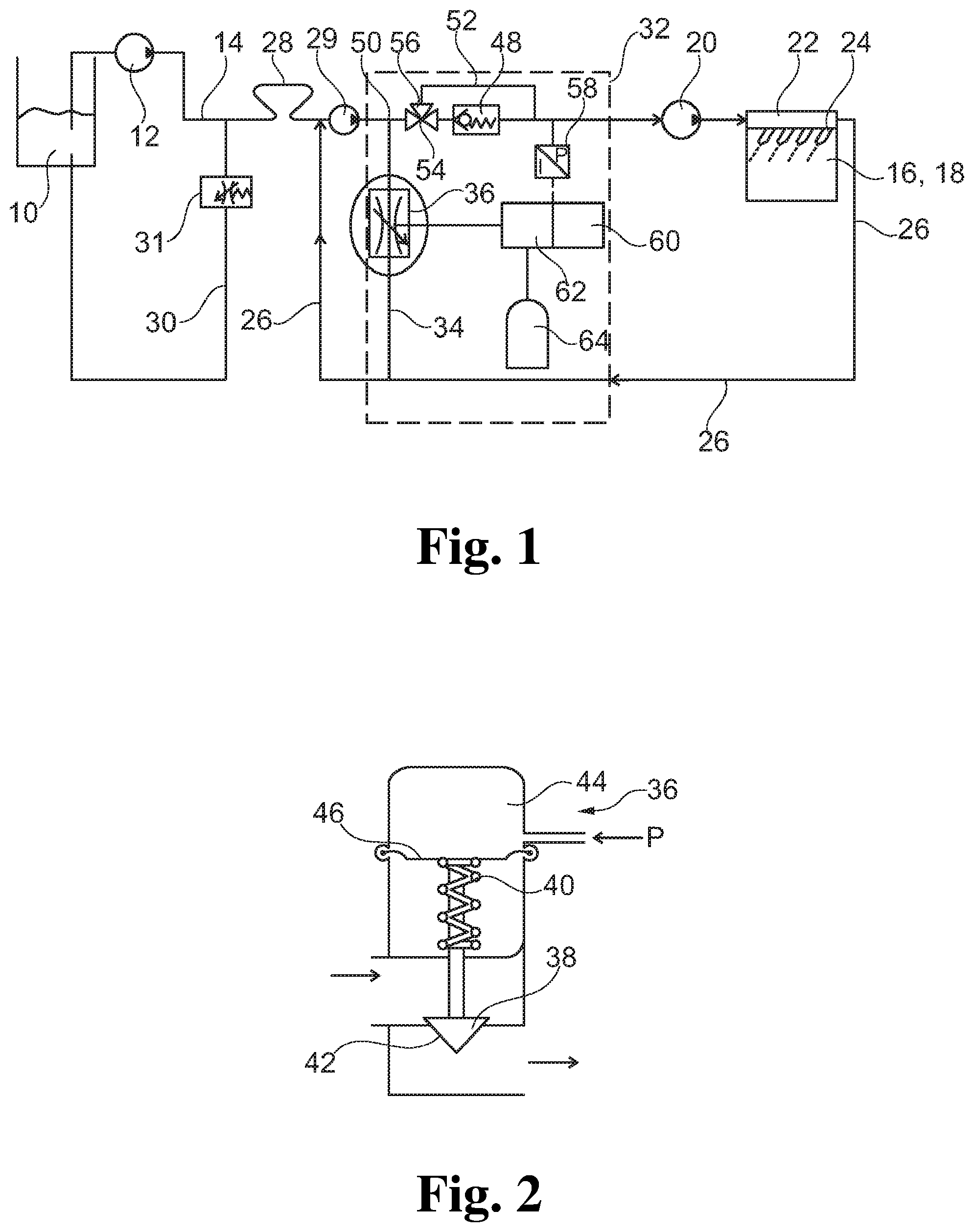
[0024] FIG. 1 shows a flow chart of a fuel consumption measurement device according to the invention having a pressure-regulating unit according to the invention.
[0025] FIG. 2 shows a pressure regulator of the pressure-regulating unit according to the invention.
[0026] The fuel consumption measurement system according to the invention is composed of a tank 10 where fuel is stored. From this tank 10, fuel is pumped into a fuel supply line 14 by means of a first fuel pump 12. The fuel supply line 14 extends to a consumer 16 which is configured as an internal combustion engine 18 having a common rail injection system in this exemplary embodiment. Accordingly, the fuel supply line 14 extends to feed pump 20 configured as high-pressure pump which forms part of the internal combustion engine and via which the fuel is fed into a common rail distributor pipe 22 and compressed. The distributor pipe 22 is fluidically connected to injection valves 24 through which the fuel is injected into the combustion chambers of the internal combustion engine 18.
[0027] Usually, in these systems, larger fuel amounts are fed than are actually injected through the injection valves 24 such that a fuel return line 26 branches off the distributor pipe 22, said fuel return line extending back to the fuel supply one 14. The returned fuel amounts can be a multiple of the injected fuel amounts.
[0028] For measuring the fuel consumption, a flowmeter 28 is arranged in the fuel supply line 14. Said flowmeter can be realized as a Coriolis meter, for example, or by parallel connection of a displacement meter having a movable piston, for example. In the fuel supply line 14, the rotatory displacement meter is arranged for measuring purposes, which displacement meter is driven by means of a drive motor. In a piston chamber, a piston displaceable in an inertia-free manner is arranged in the parallel line to the displacement device. A change of the volumetric flow in the fuel supply line 14 first results in a deflection of the piston, which deflection is measured by means of a path sensor. The measurement values are provided to a control unit which receives the values and transmits corresponding control signals to the drive motor that is controlled such that the piston is always returned into its defined initial position, the volumetric flow thus being discharged as exactly as possible via the rotatory displacement device. Since a volume fed during a time interval can be associated with each speed of the rotatory displacement device, it is possible to calculate a fuel consumption from these values.
[0029] The flowmeter measures the fuel consumption in the fuel supply line 14. The fuel return line 26 extending back to the fuel supply line 14 enters the fuel supply line 14 downstream of the flowmeter 28 and upstream of a feed pump 29 for preventing this fuel from being measured twice and being able to feed this fuel. When the consumer 16 takes up only a small amount of fuel, merely small amounts of fuel need be supplied to the measurement system through the fuel pump 12, which is why upstream of the flowmeter 28 another return line 30 branches off the fuel supply line 14, through which fuel can be returned to the tank 10 when a sufficient pressure prevails in the fuel supply line 14. In this further return line 30, a mechanical pressure regulator 31 is arranged for this purpose, via which the pressure in front of the flowmeter 28 is set. It would also be possible to regulate the pressure behind the flowmeter 28 via this mechanical flowmeter 31.
[0030] An exact fuel consumption measurement can be performed only when a constant supply line pressure prevails in the fuel supply line 14 immediately in front of the high-pressure pump 20. According to the invention, this is achieved with a pressure-regulating device 32 comprising a bypass line 34 which branches off the fuel supply line 14 and enters the fuel return line 26, wherein the branch is arranged downstream of the flowmeter 28 and downstream of the place where the fuel return line 26 enters the fuel supply line 14 and of the feed pump 20. In this bypass line 34, a pressure regulator 36 configured as a regulating valve is arranged. This pressure regulator 36 comprises a regulating body 38 which is urged away from its valve seat 42 towards the opening of the flow cross-section by a spring 40. In the present case, this pressure regulator 36 is pneumatically closed by introducing a pressure into a pressure chamber 44 which is defined by a membrane 46 connected to the regulating body 38, wherein the pressure acts, counter to the spring force, on the membrane 46, whereby the regulating body 38 is lowered to its valve seat 42 surrounding the flow cross-section once the product of the applied pressure and the surface of the membrane 46 is larger than the force of the spring 40.
[0031] In addition, the pressure-regulating device 32 is constituted of an unregulated, that is static pressure-reducing element 48 which is configured as a check valve in the present exemplary embodiment, but can also be configured as a throttle or an orifice, and is arranged in the fuel supply line 14 downstream of a branch 50 of the bypass line 34. Via this pressure-reducing element 48, a pressure drop between its outlet and its inlet occurs which merely depends on the flow velocity but is constant to a large extent.
[0032] This pressure-reducing element 48 can be bypassed via a circuitous line 52. For this purpose, a branch-off 54 is provided directly upstream of the pressure-reducing element 48, in which branch-off a 3/2-way valve 56 is arranged that serves for ensuring that the supplied fuel optionally either flows via the pressure-reducing element 48 and further through the fuel supply line 14 or through the circuitous line 52 bypassing the pressure-reducing element 48. The circuitous line 52 enters the fuel supply line 14 again directly downstream of the pressure-reducing element 48.
[0033] Downstream of the pressure-reducing element 48, and also downstream of the place where the circuitous line 52 enters the fuel supply line 14 in the present exemplary embodiment, but upstream of the feed pump 20, a pressure sensor 58 is arranged at the fuel supply line 14, via which sensor the supply line pressure in the fuel supply line 14 is measured. This pressure sensor 58 converts the pressure into a corresponding electric signal which is supplied to a control unit 60. This control unit 60 serves for controlling an electric pilot valve 62 via which a pressure from a pressure container 64 or another pressurized-air supply source is controlled and supplied to the pressure sensor 36 or the pressure chamber 44 of the pressure regulator 36. Accordingly, the pressure regulator 36 in the bypass line 34 is regulated depending on the difference between the actual values of the pressure sensor 58 and setpoints transmitted to the control unit 60.
[0034] If a central controller determines that the fuel consumption is to be measured at a supply line pressure of 1 bar in the fuel supply line 14, but the actual value measured by the pressure sensor 58 is only 0.5 bar, the pressure regulator 36 is shifted further into a closed state in that the pilot valve 62 increases the pressure fed into the pressure chamber 44. Thus, the pressure in the fuel supply line 14 increases up to the desired setpoint. If smaller setpoints are specified, they may be below atmospheric pressure since the already low pressure prevailing in front of the pressure-reducing element 48 when the pressure regulator 36 is fully open is further reduced due the pressure drop occurring at said pressure-reducing element and hence may be decreased to 0 bar or even -0.5 bar. If particularly high setpoints are required, the pressure regulator 36 can be fully closed and additionally the two-way valve 56 can be switched such that no pressure drop occurs via the pressure-reducing element 48. This bypassing of the pressure-reducing element 48 can even take place at pressures as from approximately 1.5 bar in order to reduce the load acting on the feed pump 29.
[0035] Thus, the pressure-regulating device 32 according to the invention allows exact fuel consumption measurements across a large pressure range to be performed. These consumption measurements can be performed both at maximum feed pressures of the feed pump and at low feed pressures which can be further down-regulated to -0.8 bar at the fuel supply line. The fuel pressure setpoint is thus set by the electronic control loop in a very short time taking into consideration the actual value of the pressure determined by the pressure sensor such that high regulation accuracy and velocity are achieved. This leads to very exact and reproducible measurement results of the fuel consumption measurement system such that measurements can repeatedly be taken at exactly defined measurement conditions and then compared. Due to the simple configuration of the regulating units used and the small number of elements to be regulated, the necessary number of apparatus and thus the expense are reduced as compared to prior art actively regulating pressure-regulating devices.
[0036] It is appreciated that the invention is not limited to the described exemplary embodiment and various modifications within the scope of protection of the main claim are possible. In particular, it is conceivable that instead of the pneumatic pressure regulator a hydraulic or purely electric pressure regulator can be used. Hence, the control unit of an electric regulating valve can be used with the values of the pressure sensor for direct electric control of the regulating valve, for example. Further, it is understood that various configurations of fuel consumption measurement systems are known where this pressure-regulating device can be used. Hence, in particular, the section of the fuel return line upstream of the mouth of the bypass line is omitted in the case of gasoline applications where no increased fuel feed with return flow from the distributor takes place.
* * * * *
D00000
D00001
XML
uspto.report is an independent third-party trademark research tool that is not affiliated, endorsed, or sponsored by the United States Patent and Trademark Office (USPTO) or any other governmental organization. The information provided by uspto.report is based on publicly available data at the time of writing and is intended for informational purposes only.
While we strive to provide accurate and up-to-date information, we do not guarantee the accuracy, completeness, reliability, or suitability of the information displayed on this site. The use of this site is at your own risk. Any reliance you place on such information is therefore strictly at your own risk.
All official trademark data, including owner information, should be verified by visiting the official USPTO website at www.uspto.gov. This site is not intended to replace professional legal advice and should not be used as a substitute for consulting with a legal professional who is knowledgeable about trademark law.