Portable Access Control System
Slagel; Robert Rhett
U.S. patent application number 16/817665 was filed with the patent office on 2020-07-09 for portable access control system. This patent application is currently assigned to MODULAR SECURITY SYSTEMS, INC.. The applicant listed for this patent is MODULAR SECURITY SYSTEMS, INC.. Invention is credited to Robert Rhett Slagel.
| Application Number | 20200217095 16/817665 |
| Document ID | / |
| Family ID | 36407582 |
| Filed Date | 2020-07-09 |


| United States Patent Application | 20200217095 |
| Kind Code | A1 |
| Slagel; Robert Rhett | July 9, 2020 |
PORTABLE ACCESS CONTROL SYSTEM
Abstract
A portable container is provided which comprises a passing room(s) allowing entry into a second area into a first area, the passing room having at least two openings with a walkway in-between. Barrier device(s) can be located in the walkway but not connected to the first or second opening. A control room(s) can also be provided, the control room being connected to the passing room(s).
| Inventors: | Slagel; Robert Rhett; (Ironton, OH) | ||||||||||
| Applicant: |
|
||||||||||
|---|---|---|---|---|---|---|---|---|---|---|---|
| Assignee: | MODULAR SECURITY SYSTEMS,
INC. IRONTON OH |
||||||||||
| Family ID: | 36407582 | ||||||||||
| Appl. No.: | 16/817665 | ||||||||||
| Filed: | March 13, 2020 |
Related U.S. Patent Documents
| Application Number | Filing Date | Patent Number | ||
|---|---|---|---|---|
| 16170810 | Oct 25, 2018 | 10626629 | ||
| 16817665 | ||||
| 15621517 | Jun 13, 2017 | 10138642 | ||
| 16170810 | ||||
| 15192344 | Jun 24, 2016 | |||
| 15621517 | ||||
| 14735130 | Jun 9, 2015 | 9404278 | ||
| 15192344 | ||||
| 14157011 | Jan 16, 2014 | 9051748 | ||
| 14735130 | ||||
| 13205419 | Aug 8, 2011 | 8671624 | ||
| 14157011 | ||||
| 12818899 | Jun 18, 2010 | 8015754 | ||
| 13205419 | ||||
| 10992126 | Nov 19, 2004 | 7762025 | ||
| 12818899 | ||||
| Current U.S. Class: | 1/1 |
| Current CPC Class: | E04H 3/08 20130101; G01V 5/0008 20130101; E04H 3/00 20130101; E06B 11/08 20130101; E04H 2001/1283 20130101; E04H 1/1227 20130101; E05F 2015/765 20150115; G07C 9/20 20200101; E04H 1/005 20130101; E04H 1/00 20130101; E05F 15/70 20150115; G07C 2009/0092 20130101; E04H 1/1205 20130101; E05F 15/76 20150115 |
| International Class: | E04H 1/12 20060101 E04H001/12; G07C 9/20 20060101 G07C009/20; E05F 15/70 20060101 E05F015/70; E04H 3/08 20060101 E04H003/08; E04H 1/00 20060101 E04H001/00; E06B 11/08 20060101 E06B011/08; E04H 3/00 20060101 E04H003/00; G01V 5/00 20060101 G01V005/00; E05F 15/76 20060101 E05F015/76 |
Claims
1. An access control system, comprising: a portable structure comprised of durable material enabling the structure to withstand repeated relocation of the portable structure, the portable structure comprising a floor and being configurable such that a bottom surface of the structure sits on a surface between a first area and a second area to prevent access to the second area from the first area; a plurality of barrier devices arranged in a first direction across the floor, a movable portion of each barrier device providing access through the portable structure in a second direction from the first area to the second area, the movable portion of each barrier device being controllable by a respective electronic control device of a plurality of electronic control devices within the portable structure to permit or block passage through the barrier device to thereby prevent unauthorized access from the first area into the second area; the portable structure further comprising a plurality of passing areas, each passing area comprising at least one of the plurality of barrier devices, each passing area having a first passing area opening adjacent one side of the portable structure and a second passing area opening adjacent a second side of the portable structure, wherein passage through the portable structure requires passage through at least one barrier device in a passing area to proceed from the first passing area opening to the second passing area opening.
2. The access control system of claim 1, wherein the portable structure is delivered in a turnkey state.
3. The access control system of claim 1, wherein the plurality of electronic control devices includes one or more card readers, one or more metal detectors, one or more biometric readers, one or more iris scanners, one or more fingerprint readers, one or more facial recognition technology, one or more explosive detectors, one or more electronic key locks, or one or more mechanical key locks, or a combination of two or more thereof.
4. The access control system of claim 1, wherein the portable structure further comprises at least one control area.
5. The access control system of claim 4, wherein the at least one control area includes at least one control panel that controls at least one electronic control device of the plurality of electronic control devices to enable a person to monitor the at least one passing area from the at least one control area.
6. The access control system of claim 1, wherein for each passing area the first passing area opening and the second passing area opening located on opposite sides of the portable structure.
7. An access control system, comprising: a portable structure comprised of durable material enabling the portable structure to withstand repeated relocation of the portable structure, the portable structure comprising a floor and a roof coupled to the floor by a plurality of supporting structures, the portable structure being configurable such that a bottom surface of the portable structure sits on a surface between a first area and a second area to prevent access to the second area from the first area; and a plurality of barrier devices arranged in a first direction across the floor, a movable portion of each barrier device providing access through the portable structure in a second direction from the first area to the second area, the movable portion of each barrier device being controllable by a respective electronic control device of a plurality of electronic control devices within the portable structure to permit or block passage through the barrier device to thereby prevent unauthorized access from the first area into the second area, wherein a plurality of fixed structures are coupled to the floor, each fixed structure being adjacent at least one barrier device, the plurality of fixed structures defining a plurality of paths from a first side of the portable structure through the barrier devices and to a second side of the portable structure.
8. The access control system of claim 7, wherein the portable structure is delivered in a turnkey state.
9. The access control system of claim 7, wherein the plurality of electronic control devices includes one or more card readers, one or more metal detectors, one or more biometric readers, one or more iris scanners, one or more fingerprint readers, one or more facial recognition technology, one or more explosive detectors, one or more electronic key locks, or one or more mechanical key locks, or a combination of two or more thereof.
10. The access control system of claim 7, wherein the portable structure further comprises at least one control area.
11. The access control system of claim 10, wherein the at least one control area includes at least one control panel that controls at least one electronic control device of the plurality of electronic control devices.
12. An access control system, comprising: a portable container comprised of durable material enabling the portable container to withstand repeated relocation of the portable container, and wherein the container is configurable such that a bottom surface of the container sits on a surface between a first area and a second area to prevent access to the second area from the first area; a passing room disposed in the portable container, the passing room having a first passing room opening that provides access to the portable container from the first area and a second passing room opening that provides access from the portable container to the second area; at least one turnstile located in the passing room between the first passing room opening and the second passing room opening, the at least one turnstile being positioned and sized to prevent passage from the first passing room opening to the second passing room opening without going through the turnstile; and at least one electronic control coupled to the at least one turnstile so that the at least one electronic control causes the at least one turnstile to permit or block passage through the at least one turnstile to thereby prevent unauthorized access from the first area into the second area.
13. The access control system of claim 12, wherein the portable container is delivered in a turnkey state.
14. The access control system of claim 12, wherein the at least one electronic control includes one or more card readers, one or more metal detectors, one or more biometric readers, one or more iris scanners, one or more fingerprint readers, one or more facial recognition technology, one or more explosive detectors, one or more electronic key locks, or one or more mechanical key locks, or a combination of two or more thereof.
15. The access control system of claim 12, wherein the portable container further comprises at least one control area.
16. The access control system of claim 15, wherein the at least one control area includes at least one control panel that controls the at least one electronic control to enable a person to monitor the passing room from the at least one control area.
17. The access control system of claim 12, wherein the first passing room opening and the second passing room opening located on opposite sides of the portable container.
Description
CROSS-REFERENCE TO RELATED APPLICATIONS
[0001] This application is a continuation of U.S. application Ser. No. 16/170,810 filed Oct. 25, 2018 which is a continuation of U.S. application Ser. No. 15/621,517 filed Jun. 13, 2017, now U.S. Pat. No. 10,138,642, which issued on Nov. 27, 2018, which is a continuation of U.S. application Ser. No. 15/192,344 filed Jun. 24, 2016 which is a continuation of U.S. application Ser. No. 14/735,130 filed Jun. 9, 2015, now U.S. Pat. No. 9,404,278, which issued on Aug. 2, 2016, which is a continuation of U.S. application Ser. No. 14/157,011 filed Jan. 16, 2014, now U.S. Pat. No. 9,051,748 which issued on Jun. 9, 2015, which is a continuation of U.S. application Ser. No. 13/205,419 filed Aug. 8, 2011, now U.S. Pat. No. 8,671,624 which issued on Mar. 18, 2014, which is a continuation of U.S. application Ser. No. 12/818,899 filed Jun. 18, 2010, now U.S. Pat. No. 8,015,754 which issued on Sep. 13, 2011, which is a continuation of U.S. application Ser. No. 10/992,126 filed Nov. 19, 2004, now U.S. Pat. No. 7,762,025 which issued on Jul. 27, 2010. The entirety of all of the above-listed applications are incorporated herein by reference.
FIELD OF THE INVENTION
[0002] The present invention is directed generally to access control systems and specifically to portable access control systems.
BRIEF DESCRIPTION OF THE DRAWINGS
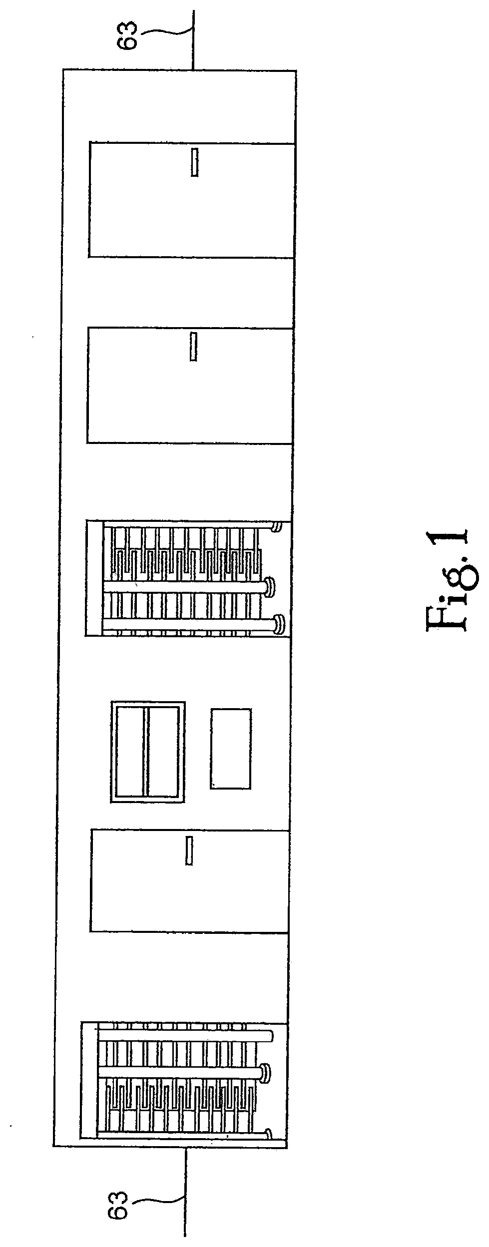
[0003] FIGS. 1 and 2 illustrate a front view and a perspective view of a portable container 110, according to embodiments of the invention.
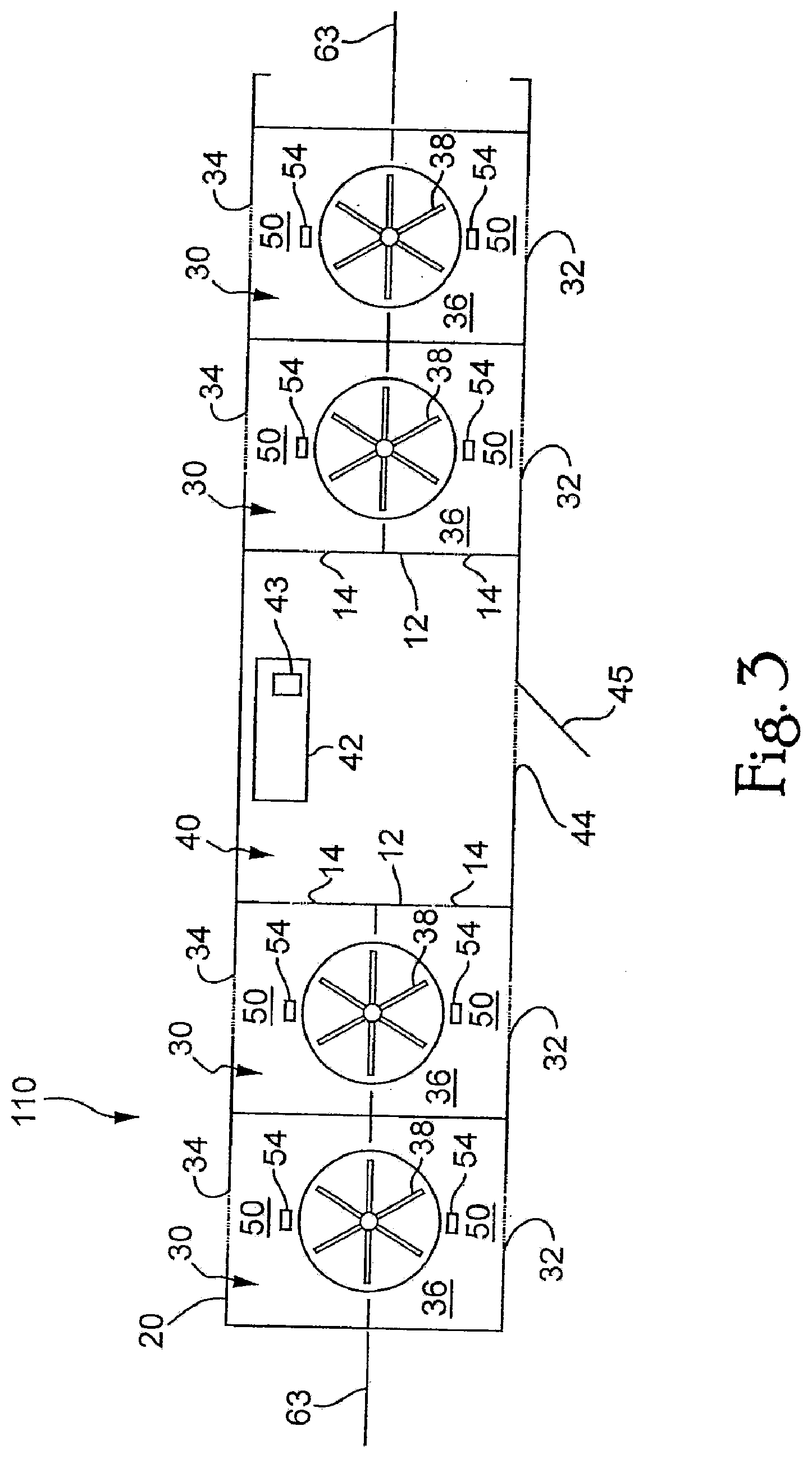
[0004] FIG. 3 illustrates a top cross-sectional view of the portable container 110, according to one embodiment of the invention.
[0005] FIG. 4 is a detailed top cross-sectional view of a passing room 30 and a control room 40, according to one embodiment of the invention.
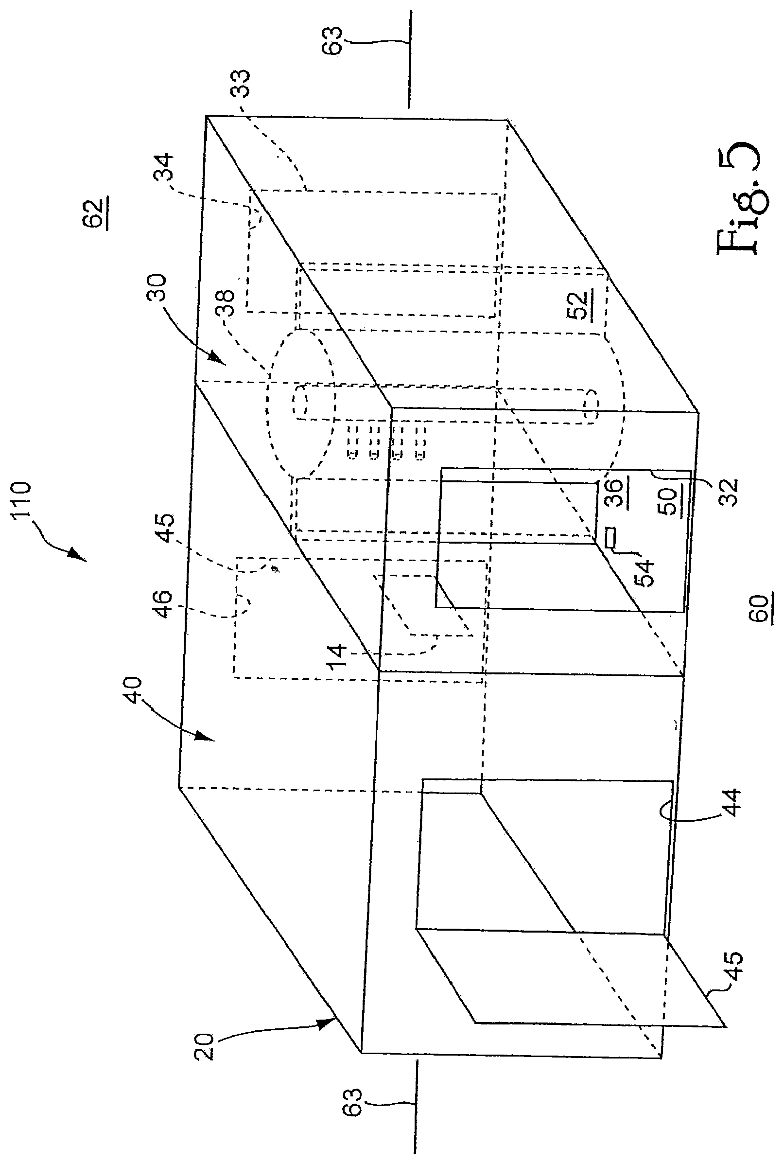
[0006] FIG. 5 illustrates a perspective view of a passing room 30 and a control room 40, according to one embodiment of the invention.
DESCRIPTION OF EMBODIMENTS OF THE INVENTION
The Containerized Access Control Unit
[0007] FIGS. 1 and 2 illustrate a front view and a perspective view of a portable container 110, according to embodiments of the invention. The portable container 110 has housing 20, which, in one embodiment, is rectangular shaped. However, any other shape is also possible. The housing 20 can be made of a durable material (e.g., iron, stainless steel), enabling the portable container 110 to be securely towed by a vehicle. One or both ends of the portable container 110 can be equipped to be towed by a vehicle. In addition, a security system to ensure that only authorized vehicles move the portable container 110 can also be included. Furthermore, fencing 63 or other material may be attached to the portable container 110 to surround a secured area 62 (e.g., see FIG. 5).
[0008] FIG. 3 illustrates a top cross-sectional view of the portable container 110, according to one embodiment of the invention. The portable container 110 comprises at least one passing room 30, which is provided for controlling and directing the movement of people between two areas. In addition, the portable container 110 can also comprise at least one control room 40, for housing a guard or supervisor.
[0009] The portable container 110 can be a standard shipping container. In one embodiment, the standard shipping container can be a shipping container which complies with international standards as determined by the International Organization for Standardization (ISO). In one embodiment, the shipping container can include the following features: made from corrugated steel; heavy steel framed to withstand repeated lifting and placing; able to hold a cargo as large as 30 tons; marine grade plywood flooring; lockable accessible doors on one or both sides of the shipping container; forklift pockets; corner connectors; or a venting system; or any combination thereof.
[0010] In one embodiment, the portable container 110 can be delivered to a user in a ready-made or turn-key state. In this case, if electricity is not required, the portable container 110 is ready to be used. If electricity is required, all that needs to be done to render the portable container 110 usable is the provision of electricity. In another embodiment, the portable container can be customized by the user to meet specific needs of the user.
[0011] FIG. 4 is a detailed top cross-sectional view of a passing room 30 and a control room 40, according to one embodiment of the invention.
[0012] Passing Room. The passing room 30 controls the movement of people between area 60 and another area 62. A fence 63 can also be used to separate areas 60 and 62 in locations where the portable containers 110 are not used. The passing room 30 has at least a first opening 32, and at least a second opening 34, which in one embodiment is on a side opposite the first opening 32. However, the first opening 32, second opening 34, and additional openings can be located on any side of the passing room 30, including being located on the same side of the passing room 30. The second opening 34 is spaced apart from the first opening 32 so as to define a walkway 36 in-between. A closing device 33 (e.g., a door, shutters) is employed to close the openings 32 and 34 when passing room 30 is not in use. A security sensing device for safeguarding the closing device 33 can be employed.
[0013] The portable container 110 can comprise at least one barrier device 38 in the inside of the passing room 30, which restricts a person's movement through the passing room 30. In one embodiment, a turnstile (e.g., a full-body turnstile, a partial-body turnstile, a bi-directional turnstile, or a uni-directional turnstile) is employed as a barrier device of the portable container 110, but other barrier device may be used to restrict a person's movement through the passing room 30. For example, a sliding door, a revolving door, moving bars, and gates may be used as a barrier device. The barrier device 38 is located inside the walkway 36, defining a first space 50 between the barrier device 38 and the first opening 32, and defining a second space 52 between the barrier device 38 and the second opening 34.
[0014] In one embodiment, the passing room 30 can alternatively include at least one security device 54 issuing permission for a person to pass through the passing room 30. In one embodiment, the security device 54 can comprise, but is not limited to, one or more card readers, metal detectors, biometric readers, iris scanners, fingerprint or palm readers, explosive detectors, physical or facial recognition technology, electronic key locks, or mechanical key locks, or any combination thereof. The security device 54 can also include a security measure, such as, but not limited to, posting an individual proximate to the barrier device 38 to check identification cards (e.g., photo identification cards, licenses). In one embodiment, a security device 54 is located in the first space 50 and also in the second space 52. Security devices 54 can be included inside or outside of the passing room.
[0015] The passing room 30 can also comprise lighting.
[0016] Control Room. In one embodiment, a control room 40 is provided for housing a guard or supervisor. The control room 40 can include a control panel 42 to control the barrier device(s) 38 and the security device(s) 54 in order for a guard or supervisor to monitor the passing room while staying in the control room 40. The control panel 42 can comprise an alarm device 43 which gives an alarm in case a problem occurs in the passing room 30.
[0017] The control room 40 and the passing room 30 are separated by at least one wall 12. The wall 12 can comprise at least one window 14, so that a guard in the control room 40 can observe the inside of the passing room 30 or the outside of the portable container 110. The control room 40 has at least one opening 44 with at least one closing device 45. The closing device(s) 45 of the control room 40 can be the same as, or different from, the closing device(s) 33 of the passing room 30.
[0018] The control room 40 can also comprise: heat and/or air-conditioning; lighting; at least one computer/cable outlet; at least one phone jack; at least one electrical outlet; at least one vent; or insulation; or any combination thereof.
[0019] FIG. 5 illustrates a perspective view of a passing room 30 and a control room 40, according to one embodiment of the invention. As the portable container 110 has a housing 20 which comprises both the at least one passing room 30 and the at least one control room 40, it is easy for users to move and use almost anywhere. The portable container has everything that a user needs to control access to an area.
Use of the Containerized Access Control Unit
[0020] The portable container 110 can be put on a vehicle or trailer and transported or towed to reach multiple destinations, and can be used to control access to an area. The portable container may be used by people who have an access device (e.g., people working on a construction site). The access device is read by the security device. The portable container 110 may also be used by people that do not have an access device, but who must pass through security to enter a venue (e.g., an outside concert).
[0021] Use with Access Device. If the portable container 110 is being used in conjunction with an access device, when a person approaches the passing room 30 from an area 60 and enters the first opening 32, the person can stay in the first space 50 in the walkway 36 and present an access device (e.g., identification or electronically read card) to the security device 54. In one embodiment, because the security device 54 is located inside the passing room, the chance that the person will lose or break an identification card or device is decreased because the person does not need to expose the identification card or device outside of the portable container 110. The portable container 110 also protects the security device 54, because the security device 54 is located inside of the passing room 30.
[0022] In one embodiment, the barrier device remains locked or closed until the access device is successfully read by the security device 54. Once a person is approved by the security device 54, the barrier device 38 is unlocked and the person can go through the barrier device 38. If a person is not approved by the security device 54, the barrier device 38 continues to be kept locked, and, the control panel 42 can give an alarm to a guard via the alarm device 43.
[0023] Use without Access Device. If the portable container 110 is being used without an access device, when a person approaches the passing room 30 from an area 60 and enters the first opening 32, the person can stay in the first space 50 in the walkway 36 and go through the security device 54 (e.g., a metal detector). In one embodiment, the barrier device 38 can be the same device as the security device 54 (e.g., the metal detector). In another embodiment, a separate barrier device can be used to stop persons from accessing the secured area 62. The barrier device 38 remains locked or closed until the security device 54 or security personnel authorizes a person to enter the secured area 62. Once a person is approved, the barrier device 38 is unlocked and the person can go through the barrier device 38. If a person is not approved, the barrier device 38 continues to be kept locked, and, the control panel 42 can give an alarm to a guard via the alarm device 43. Alternatively, the barrier device can remain open until locked by security personnel, for example.
Manufacturing of the Containerized Access Control Unit
[0024] In one embodiment, a standard shipping container is filled with material to be shipped at a first location. Then, the container is shipped to a second location. The container is next unloaded at the second location. Next, the container is outfitted as an access control unit after the container is unloaded. In one embodiment, the second location can be overseas from the first embodiment.
CONCLUSION
[0025] While various embodiments of the present invention have been described above, it should be understood that they have been presented by way of example, and not limitation. It will be apparent to persons skilled in the relevant art(s) that various changes in form and detail can be made therein without departing from the spirit and scope of the present invention. In fact, after reading the above description, it will be apparent to one skilled in the relevant art(s) how to implement the invention in alternative embodiments. Thus, the present invention should not be limited by any of the above-described exemplary embodiments.
[0026] In addition, it should be understood that the figures, which highlight the functionality and advantages of the present invention, are presented for example purposes only. The architecture of the present invention is sufficiently flexible and configurable, such that it may be utilized in ways other than that shown in the accompanying figures.
[0027] Further, the purpose of the Abstract of the Disclosure is to enable the U.S. Patent and Trademark Office and the public generally, and especially the scientists, engineers and practitioners in the art who are not familiar with patent or legal terms or phraseology, to determine quickly from a cursory inspection the nature and essence of the technical disclosure of the application. The Abstract of the Disclosure is not intended to be limiting as to the scope of the present invention in any way.
* * * * *
D00000
D00001
D00002
D00003
D00004
D00005
XML
uspto.report is an independent third-party trademark research tool that is not affiliated, endorsed, or sponsored by the United States Patent and Trademark Office (USPTO) or any other governmental organization. The information provided by uspto.report is based on publicly available data at the time of writing and is intended for informational purposes only.
While we strive to provide accurate and up-to-date information, we do not guarantee the accuracy, completeness, reliability, or suitability of the information displayed on this site. The use of this site is at your own risk. Any reliance you place on such information is therefore strictly at your own risk.
All official trademark data, including owner information, should be verified by visiting the official USPTO website at www.uspto.gov. This site is not intended to replace professional legal advice and should not be used as a substitute for consulting with a legal professional who is knowledgeable about trademark law.