Fence Comprising Fence Modules
MESSELIS; Timothy
U.S. patent application number 16/648986 was filed with the patent office on 2020-07-09 for fence comprising fence modules. The applicant listed for this patent is GUARDIAR EUROPE BVBA. Invention is credited to Timothy MESSELIS.
| Application Number | 20200217029 16/648986 |
| Document ID | / |
| Family ID | 60083370 |
| Filed Date | 2020-07-09 |


| United States Patent Application | 20200217029 |
| Kind Code | A1 |
| MESSELIS; Timothy | July 9, 2020 |
FENCE COMPRISING FENCE MODULES
Abstract
Fence comprising at least a first and a second fence module (1), wherein said fence modules (1) comprise a base (2) with a receptacle for a substance, wherein the first fence module (1) comprises a first connecting element (3a) with an upright passage (4a), the second fence module (1) comprises a second connecting element (3b) with an upright passage (4b), and the fence comprises a connecting rod (5) for extending through both said passages (4a, 4b) to connect the fence modules (1) to each other, and in that in a connected state of the fence modules (1), these fence modules (1) can occupy at least two positions with regard to each other, being a first position where the distance between the said passages (4a, 4b) along the connecting rod (5) is minimal and a second position where the distance between the said passages (4a, 4b) along the connecting rod (5) is maximal.
| Inventors: | MESSELIS; Timothy; (Lauwe, BE) | ||||||||||
| Applicant: |
|
||||||||||
|---|---|---|---|---|---|---|---|---|---|---|---|
| Family ID: | 60083370 | ||||||||||
| Appl. No.: | 16/648986 | ||||||||||
| Filed: | September 20, 2017 | ||||||||||
| PCT Filed: | September 20, 2017 | ||||||||||
| PCT NO: | PCT/IB2017/055684 | ||||||||||
| 371 Date: | March 19, 2020 |
| Current U.S. Class: | 1/1 |
| Current CPC Class: | E01F 13/12 20130101; E01F 15/085 20130101; E01F 13/022 20130101; E01F 15/088 20130101 |
| International Class: | E01F 15/08 20060101 E01F015/08; E01F 13/12 20060101 E01F013/12 |
Claims
1. A fence comprising at least a first and a second fence module which are consecutive connectable to each other, wherein said fence modules comprise a base with a receptacle for a substance such as concrete, gravel, water or sand, wherein the first fence module comprises a first connecting element with an upright passage, the second fence module comprises a second connecting element with an upright passage, and the fence comprises a connecting rod for extending through both said passages to connect the fence modules to each other, and wherein in a connected state of the fence modules, these fence modules can occupy at least two positions with regard to each other, being a first position where the distance between the said passages along the connecting rod is minimal and a second position where the distance between the said passages along the connecting rod is maximal.
2. The fence according to claim 1, wherein the base of each fence module comprises the respective connecting element.
3. The fence according to claim 1, wherein, viewed along the connecting rod in a connected state, the sum of both the dimensions of the passages is smaller than the corresponding dimension of the connecting rod such that the fence modules can occupy in a connected state different positions with regard to each other having different distances between the passages.
4. The fence according to claim 1, wherein the connecting rod is an elongated rod and wherein the first and the second passage can be brought into alignment according to a first direction, and wherein the connecting rod extends through both said passages along substantially said first direction in a connected state.
5. The fence according to claim 1, wherein in a connected state, the first fence module and the second fence module are rotatable with regard to each other along the connecting rod.
6. The fence according to claim 4, wherein in a connected state, the first fence module and the second fence module are rotatable with regard to each other along the said first direction.
7. The fence according to claim 5, wherein the connecting rod has a tubular shape and the first and the second passage have a tubular shape.
8. The fence according to claim 1, wherein the first module comprises a third connecting element with an upright passage wherein the passage of the third connecting element extends at a distance from the passage of the first connecting element and wherein, in a connected state, the passage of the second connecting element extends between the passages of the first and the third connecting element and the connecting rod extends through the three said passages, and wherein, viewed along the connecting rod the dimension of the second connecting element, is smaller than the dimension of the space between the first and the third connecting element, such that the passage of the second connecting element can occupy different positions along the connecting rod within said space, such that in a connected state the fence modules can occupy different positions with regard to each other.
9. The fence according to claim 8, wherein the passages of the first and the third connecting element are aligned.
10. The fence according to claim 8, wherein the first and the third connecting element form protrusions of the first fence module such that a groove extends between said first and third connecting element and wherein in that the second connecting element forms a protrusion of the second fence module wherein said second connecting element extends substantially within said groove in a connected state.
11. The fence according to claim 10, wherein the section of the groove according to the plane in which the first direction and the lengthwise direction of the said fence module extends, has the shape of an isosceles trapezoid and wherein the second connecting element according to the plane in which the first direction and the lengthwise direction of the said fence module extends, also has the shape of an isosceles trapezoid.
12. The fence according to claim 1, wherein the base comprises a frame and outer plates connected to said frame, wherein said frame and outer plates form the said receptacle and the outer plates form the edges of the receptacle.
13. The fence according to claim 12, wherein the frame comprises several reinforcement beams which are interconnected to each other.
14. The fence according to claim 13, wherein the frame comprises several hollow elements which form the said passages, wherein each said hollow element at least extends partly within a said reinforcement beam.
15. The fence according to claim 8, wherein an outer plate forms the front plate, and the frame comprises at least three of said reinforcement beams which are respectively connected to and lie against, according to the lengthwise direction of the fence module and at a distance from each other, the top of the front plate, the central part of the front plate according to the height direction and the bottom of the front plate, wherein each hollow element extends within a said respective reinforcement beam, such that part of each said reinforcement beam forms part of a said respective connecting element.
16. The fence according to claim 1, wherein the second fence module also comprises a said first connecting element and the first fence module also comprises a said second connecting element, wherein said first and second connecting element of each fence module are located at opposite sides of the fence module.
17. The fence according to claim 1, wherein at least one fence module comprises a panel which is supported on the base and which extends upright and in which the base comprises the said connecting element, wherein said connecting element is located on a side of the base at the height of a side of the panel according to the lengthwise direction of the panel.
18. The fence according to claim 16, wherein the panel substantially extends between said first and second connecting element of the fence module, viewed along the lengthwise direction of the panel.
19. The fence according to claim 1, wherein the base comprises a front side and a back side and the base has a certain depth between said front side and back side, the passages are located at the height of the front side and wherein the maximal length dimensions of the base decreases from the passages on to the back side.
20. The fence according to claim 1, wherein the base comprises at the height of its bottom an anti-slip layer.
Description
[0001] The present invention relates to a fence comprising at least a first and a second fence module which are consecutive connectable to each other, wherein said fence modules comprise a base with a receptacle for a substance such as concrete, gravel, water or sand.
[0002] Such a fence preferably comprises several such fence modules which are successively connected to each other, such that the fence has a certain length.
[0003] At sites where many people gather together, such as sites where sporting events, rock concerts, markets, festivals, etc., take place, it is desirable to have suitable safety measures in place in order to guarantee the safety of these people. These safety measures include barrier systems, such as fences, to prevent people and/or vehicles to enter these sites. These fences need to be solid and strong in order to effectively stop potential intruders. They also need to be able to absorb impacts from vehicles such as cars, trucks etc. because terrorists can attempt to enter the site with a moving vehicle. Therefore, the fence modules comprise a base with a receptacle for a substance such as concrete, gravel, water or sand. The weight of the base increases the weight of the fence module, thus preventing people and or vehicles to tip over the fence modules and/or preventing the displacement of the fence modules single handed once the fence is placed. In most cases the fence module will also comprise a panel or something similar such as a ballistic panel according to the standard UL752/NIJ0101.06 or a panel made of polycarbonate. The base then also supports this panel. However, the fence modules do not have to comprise a panel because the base can also be used as such. These fences can be used for temporary, semi-permanent or permanent access protection of sites. Preferably these fences are crash rated and tested according to standards such as IWA14, ASTM F2656 and/or PAS 68.
[0004] Since these events are usually temporary events, these fences are often temporary fences which makes it desirable that these fences can be placed rapidly and in a simple manner. By using fence modules, one can place the fence modules for example one by one and next to each other and then connect these fence modules to each other as such to form a fence of the desired length. These fence modules can be for example of such a shape that they can easily be picked up and placed at the desired location by a forklift.
[0005] At many sites the surface is not flat. For example there can be irregularities such as curbstones, tree rotes, slopes, (speed) bumps, holes, etc. With existing fence modules, these irregularities obstruct the good connection of the fence modules to each other, meaning that the strength of the fence at the height of said irregularities is smaller and/or meaning that measurements have to be taken to circumvent these irregularities and for example more fence modules are needed because the fence has to go around these irregularities.
[0006] It is therefore an object of the invention to provide a strong and effective fence that can be rapidly placed in a simple manner at the desired site and which can be placed upon a surface with irregularities in a simple and effective manner.
[0007] This object is achieved by providing a fence comprising at least a first and a second fence module which are consecutive connectable to each other, wherein said fence modules comprise a base with a receptacle for a substance such as concrete, gravel, water or sand, wherein the first fence module comprises a first connecting element with an upright passage, the second fence module comprises a second connecting element with an upright passage, and the fence comprises a connecting rod for extending through both said passages to connect the fence modules to each other, and wherein in a connected state of the fence modules, these fence modules can occupy at least two positions with regard to each other, being a first position where the distance between the said passages along the connecting rod is minimal and a second position where the distance between the said passages along the connecting rod is maximal.
[0008] With a connected state, a state is meant where the fence modules are connected to each other with the aid of the connecting rod. This rod is then placed through both the passages of the fence modules, and preferably throughout the entire length of both said passages such as to ensure a strong connection between said fence modules, wherein said connection is able to withstand impacts from vehicles.
[0009] These fence modules can occupy at least two positions with regard to each other in a connected state, meaning that when one fence module is located higher than the other fence module lying next to it, and this as a result of irregularities such as holes, curbstones, tree rotes, bumps, etc., these fence modules can still be connected to each other in a good manner. These differences of height of the surface caused by irregularities do not prevent fence modules to be connected to each other, such that these fences can be placed at the most suitable location even if the surface at this location is not completely flat. Preferably the receptacle is filled with concrete and even more preferably the receptacle is already filled with concrete before the fence modules are placed to form the fence.
[0010] With the distance between the passages viewed along the connecting rod, the minimal distance between said passages, viewed along said connecting rod, is indicated. Preferably the cross section of the connecting rod is somewhat smaller than the corresponding dimensions of said passages, such that the connecting rod can be easily placed into the said passages, but still can provide sufficient strength to the connection.
[0011] Preferably the base of each fence module comprises the respective connecting element. The connection of the fence modules then takes place at the height of the base, thus relatively low, meaning that slopes and/or angles between the surfaces of the bases of two consecutive fence modules, which are placed upon the ground, do not prevent a good connection of the fence modules. These slopes and/or angles are caused by placing the bases upon a surface with irregularities. The cross section of the connecting rod is preferably somewhat smaller than the corresponding dimensions of said passages, such that these slopes and/or angles do not cause problems to connect the fence modules to each other.
[0012] These fences can also be used as windshields and/or sound barriers and/or ballistic barriers and can thus can also be placed next to airports, roads, industrial sites, public buildings etc.
[0013] In a preferred embodiment is, viewed along the connecting rod in a connected state, the sum of both the dimensions of the passages smaller than the corresponding dimension of the connecting rod such that the fence modules can occupy in a connected state different positions with regard to each other having different distances between the passages. To connect the fence modules to each other, thus to place the connecting rod into the said passages, the connecting rod is placed along a direction of movement into said passages. Preferably the wording viewed along the connecting rod corresponds to the wording viewed along the said direction of movement. Because the said dimension of the connecting rod is larger than the sum of both the dimensions of the passages, this means that the connecting rod can extend throughout both the entire passages, while there is some distance between said passages, meaning that the connection between the fence modules is good even when the passages are spaced somewhat away from each other.
[0014] Preferably the connecting rod is an elongated rod, the first and the second passage can be brought into alignment according to a first direction, and the connecting rod extends through both said passages along substantially said first direction in a connected state. The rod here has a lengthwise direction. Since the said passages can be brought into alignment and thus extend along one direction, here the first direction, an elongated rod can be easily placed trough said aligned passages to connect the passages to each other. Preferably said passages are also elongated, wherein their lengthwise direction preferably corresponds to the said first direction in a connected state of the fence modules. The connecting rod then extends over a sufficient length into said passages and such ensures a strong connection between the fence modules. Here preferably, the sum of both the lengths of the passages is smaller than the length of the connecting rod. Said first direction is preferably an upright direction. Even more preferably the said first direction is approximately the height direction of a said fence module.
[0015] In a very preferred embodiment the first fence module and the second fence module are rotatable with regard to each other along the connecting rod in a connected state. This means that angles between the fence modules, viewed along the length of the fence, are possible. A said angle lies preferably between 0.degree. and 45.degree.. A fence module which is placed upon a flat surface normally has a height direction perpendicular to said surface, a length direction and a width direction, wherein the fence modules are situated next to each other as such that the lengths of two consecutive fence modules determine the length of the fence. Here one does not have to provide in adapted fence modules, such as corner fence modules, to form angles.
[0016] Further preferably, when the connecting rod is an elongated rod as described above, the first fence module and the second fence module are rotatable with regard to each other along the said first direction.
[0017] Also further preferably the connecting rod has a tubular shape and the second passage has a tubular shape. Herewith it is very easy to form the desired angle between the fence modules. The diameter of the passages is preferably somewhat larger than the diameter of the tubular connecting rod such that the fence modules can easily rotate with regard to each other.
[0018] In a preferred embodiment the first module comprises a third connecting element with an upright passage wherein the passage of the third connecting element extends at a distance from the passage of the first connecting element and wherein, in a connected state, the passage of the second connecting element extends between the passages of the first and the third connecting element and the connecting rod extends through the said three passages, and in that viewed along the connecting rod the dimension of the second connecting element, is smaller than the dimension of the space between the first and the third connecting element, such that the passage of the second connecting element can occupy different positions along the connecting rod within said space, such that in a connected state the fence modules can occupy different positions with regard to each other. Here there is a third passage and the second connecting element extends between the first and third connecting element, such that a strong connection is obtained when the connecting rod extends through all said three passages. The position of the second connecting element between the third and first connecting is in function of the surface on which the fence modules are placed.
[0019] Further preferably the passages of the first and the third connecting element are aligned. The connecting rod is than preferably an elongated rod, and preferably the first and the second passage can be brought into alignment according to a first direction, such that the connecting rod extends through all said passages along substantially said first direction in a connected state. Also further preferably the dimension of the second connecting element along the said first direction, when the passages are aligned, is smaller than the corresponding dimension of the space between the first and the second element, such that the passage of the second connecting element is movable according to said first direction.
[0020] The first and the third connecting element preferably form protrusions of the first fence module such that a groove extends between said first and third connecting element and also then preferably the second connecting element forms a protrusion of the second fence module wherein said second connecting element extends substantially within said groove in a connected state. Such a shape of the connecting elements is capable of withstanding impact forces of a vehicle, when a connecting rod is placed in the said passages.
[0021] Further preferably the section of the groove according to the plane in which the first direction and the lengthwise direction of the said fence module extends, has the shape of an isosceles trapezoid and the second connecting element according to the plane in which the first direction and the lengthwise direction of the said fence module extends also has the shape of an isosceles trapezoid. A fence module which is placed upon a flat surface normally has a height direction perpendicular to said surface, a length direction and a width direction, wherein the fence modules are situated next to each other as such that the lengths of two consecutive fence modules lie in line with each other and determine the length of the fence. The smallest parallel side of the said trapezoid of the second connecting element then preferably forms an outer edge of the second connecting element, the smallest parallel side of the said trapezoid of the groove then forms an edge of the fence module and the said trapezoid of the second connecting element is smaller than the said trapezoid of the groove. Here the second connecting element can easily take different positions along the connecting rod in a connected state.
[0022] In very preferred embodiment the second fence module also comprises a said first connecting element and the first fence module also comprises a said second connecting element, wherein said first and second connecting element of each fence module are located at opposite sides of the fence module. Each fence module then comprises a first and a second connecting element such that they can be connected to another fence module at the height of both of the said sides. If the fence comprises more than two consecutive fence modules, preferably all the fence modules or at least the fence modules which or not located at the edges of the fence are constructed according to this very preferred embodiment. This makes it easy to construct a fence of the desired length. Preferably each fence module has a height direction, a length direction and a width direction, wherein the fence modules are situated next to each other as such that the lengths of two consecutive fence modules determine the length of the fence. Preferably the first and the second connecting element are located at opposite sides according to the length direction such that two fence modules can easily be connected to each other to form a fence with a certain length.
[0023] Preferably at least one fence module comprises a panel which is supported on the base and which extends upright, the base comprises the said connecting element, and wherein said connecting element is located on a side of the base at the height of a side of the panel according to the lengthwise direction of the panel. The base here supports the panel. The panel can be a wire panel with for example galvanized steel wires or the panel can be a plastic panel (for example polycarbonate) or the panel can be a ballistic panel according to the standard UL752/NIJ0101.06.
[0024] Further preferably if the fence module comprises a first connecting element and a second connecting element, wherein said first and second connecting elements are located at opposite sides of the fence module, the panel substantially extends between said first and second connecting element of the fence module, viewed along the lengthwise direction of the panel.
[0025] In a preferred embodiment, the base comprises a frame and outer plates connected to said frame, wherein said frame and outer plates form the said receptacle and the outer plates form the edges of the receptacle. The frame ensures that the base has sufficient strength and is capable of withstanding impact forces caused by, for example, vehicles. The plates form the casing into which the substance such as concrete, gravel, sand, water, can be placed. Water can be placed into the receptacle with the aid of bags or other elements filled with water. Preferably one or several of the outer plates can be easily removed from the frame and/or the other plates and then can be reconnected, such that the receptacle can be easily filled with the said substance.
[0026] Further, the frame preferably comprises several reinforcement beams which are interconnected to each other. Further preferably these beams are made of metal such as galvanized steel.
[0027] Even more preferably the frame further comprises several hollow elements which form the said passages, wherein each said hollow element at least extends partly within a said reinforcement beam. The passages here are firmly supported, such that the connection between two consecutive fence modules is strong.
[0028] An outer plate preferably forms a front plate of the receptacle, and the frame preferably comprises at least three of said reinforcement beams which are respectively connected to and lie against, according to the lengthwise direction of the fence module and at a distance from each other, the top of the front plate, the central part of the front plate according to the height direction and the bottom of the front plate, wherein each hollow element extends within a said respective reinforcement beam, such that part of each reinforcement beams forms part of a said respective connecting element. This is a very strong embodiment. When a panel is present, the panel is preferably attached upon the upper reinforcement beam of said three reinforcement beams.
[0029] The base is preferably provided with openings at the bottom, provided to be engaged with by forks of a forklift truck in order to lift up this fence module. In this way, the fence modules can be easily placed when needed.
[0030] In a preferred embodiment, the base comprises a front side and a back side and the base has a certain depth between said front side and back side, the passages are located at the height of the front side and the maximal length dimensions of the base decreases from the passages on to the back side. In this way, the fence modules can be connected to each other such that the length directions of the fence modules form an angle.
[0031] Preferably the base comprises at the height of its bottom an anti-slip layer. When a vehicle crashes into the fence, this anti-slip layer helps preventing the sliding of a said fence module, such that the fence hardly moves when being hit by a vehicle. With the aid of said anti-slip layer the fence modules can also be placed upon slippery surfaces. This anti-slip layer can be for example a rubber layer.
[0032] The present invention is now explained in greater detail below with reference to the following detailed description of some preferred embodiments of a fence according to the present invention. The aim of this description is solely to give illustrative examples and indicate further advantages and particularities and thus cannot be interpreted as a limitation of the field of application of the invention or of the patent rights claimed in the claims.
[0033] In this detailed description, reference is made by means of reference numerals to the appended drawings, wherein
[0034] FIG. 1 is a front view of a fence module according to a first embodiment of the invention;
[0035] FIG. 2 is a perspective view of the fence module of FIG. 1;
[0036] FIG. 3 is a rear view of the fence module of FIGS. 1 and 2;
[0037] FIG. 4 is another perspective view of the fence module of FIGS. 1 to 3;
[0038] FIG. 5 is a front view of a fence according to the invention comprising two fence modules a shown in FIGS. 1 to 4;
[0039] FIG. 6 is a perspective view of the fence as shown in FIG. 5;
[0040] FIG. 7 is a back view of the fence as shown in FIGS. 5 and 6;
[0041] FIG. 8 is another perspective view of the fence as shown in FIGS. 5 to 7;
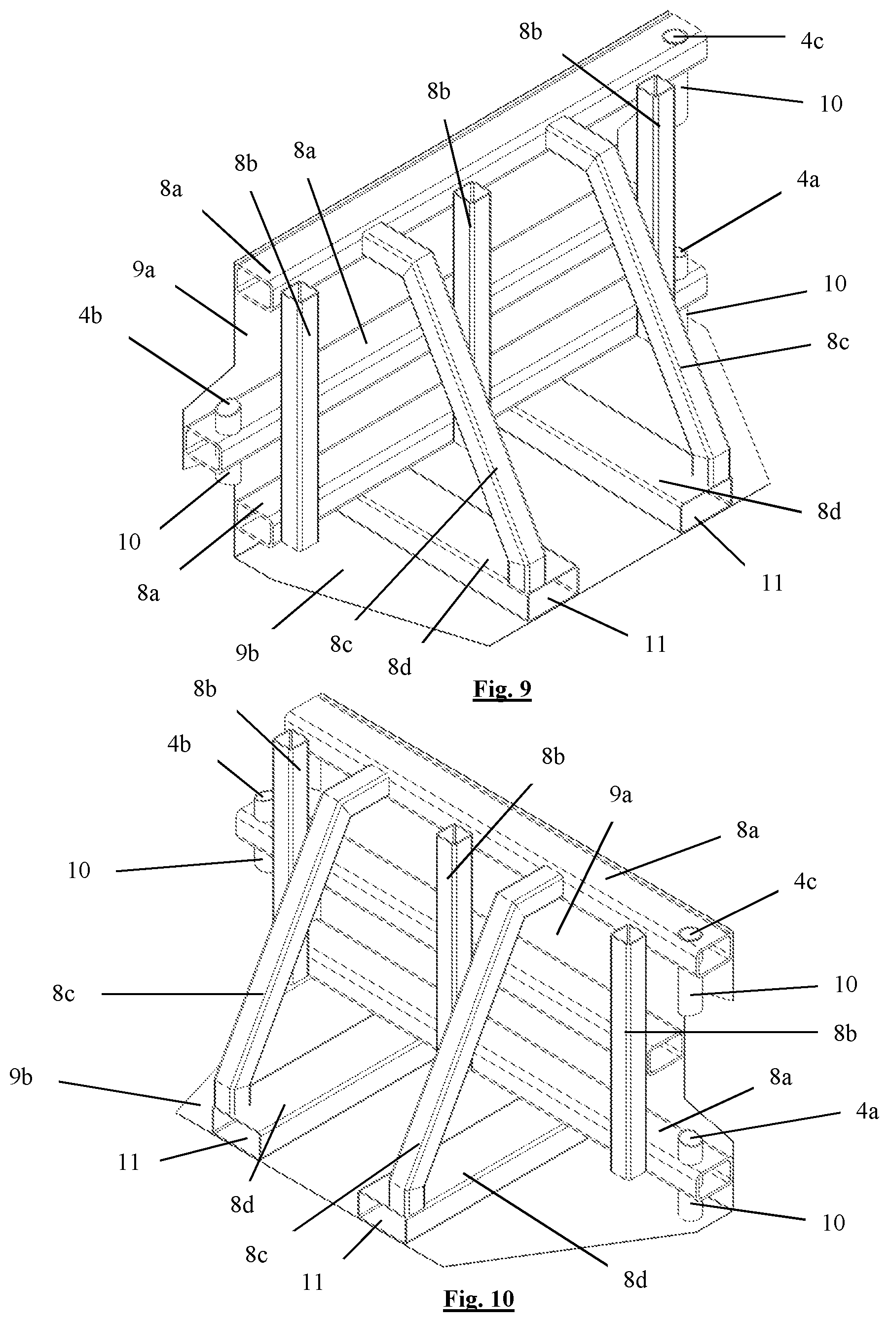
[0042] FIG. 9 is a perspective view of the frame and part of the outer plates of the base of the fence module as shown in FIGS. 1 to 4;
[0043] FIG. 10 is another perspective view of the frame and part of the outer plates as shown in FIG. 9;
[0044] FIG. 11 is a back view of a fence module according to a second embodiment of the invention;
[0045] FIG. 12 is a perspective view of a fence comprising two fence modules as shown in FIG. 11
[0046] The fence, as shown in the figures, comprises a first and a second fence module (1) which are consecutive connectable to each other. Each fence module (1) has a similar design and comprise a base (2) with a receptacle, wherein said receptacle is filled with concrete, and comprises a panel (7) which is supported by the base (2).
[0047] The fence module (1) has a height direction (A) which extends according to the vertical direction when placed upon a horizontal flat surface, a length direction (B) and a width direction (C). The fence modules (1) are situated next to each other as such that the lengths of two consecutive fence modules (1) lie in line with each other and determine the length of the fence. Each fence module (1) has a height of approximately 2.5 m, a length of approximately 2.6 m and a depth of approximately 0.7 m.
[0048] The base (2) of the fence module (1) has a first connecting element (3a), a second connecting element (3b) and a third connecting element (3c). The first and the third connecting elements (3a, 3c) are located on one side of the base (2) according to the lengthwise direction of the fence module (1) and the second connecting element (3b) is located on said other side of the base (2). Each connecting element (3a, 3b, 3c) forms a protrusion of the base (2) according to said lengthwise direction. Each connecting element (3a, 3b, 3c) comprises an elongated passage (4a, 4b, 4c) which extends according to the height direction (A).
[0049] The first and the third connecting element (3a, 3c) are located at a distance from each other such that a groove (6) extends between said first and third connecting element (3a, 3c). This groove (6) has, according to the plane in which the height direction (A) and the lengthwise direction (B) of the fence module (1) extends, the shape of an isosceles trapezoid, wherein the smallest of the parallel sides forms an edge of the base (2). The second connecting element (3b) according to the plane in which the height direction (A) and the lengthwise direction (B) of the fence module (1) extends, also has the shape of an isosceles trapezoid, with the smallest of the parallel sides forming an edge of the base (2).
[0050] To connect the fence modules (1) to each other, the second connecting element (3b) of a said fence module (1) is placed in the groove (6) between the first and third connecting element (3a, 3c) of another fence module (1) in such a manner that the passages (4a, 4b, 4c) of said first, second and third connecting element (3a, 3b, 3c) are substantially aligned and a tubular elongated connecting rod (5) can be placed into said three passages (4a, 4b, 4c) to connect the fence modules (1) to each other. The second connecting element (3b) is smaller than the said groove (6) such that it can occupy different positions in the groove (6) in function of the surface upon which the fence modules (1) are placed. The diameter of the elongated rod (5) is approximately 40 mm and the said passages (4a, 4b, 4c) also have a tubular shape with a diameter which is slightly larger than the diameter of the elongated rod (5).
[0051] Further the base (2) comprises a front side and a back side, according to the depth direction (C) and the base (2) has a certain depth between said front side and back side, the connecting elements (3a, 3b, 3c) are located at the height of the front side and the maximal length dimensions of the base (2) decreases from the connecting elements (3a, 3b, 3c) on to the back side. This ensures that the connected fence modules (1) can pivot backwords along the height direction (A). This ensures that angles are possible between the connected fence modules (1).
[0052] The base (2) further comprises a frame and plates (9a, 9b) which form the receptacle, wherein said plates (9a, 9b) are attached to the frame and form the edges of the base (2). The plates (9a, 9b) comprises a front plate (9a) which extends according to the height direction (A) and the length direction (B), side plates, back plates which form the back side, a top plate and a bottom plate (9b) which is provided to rest upon the surface upon which the fence is placed. In the second embodiment according to the invention, as shown in FIGS. 11 and 12, the top plate is removable connected to the rest of the base (2) with the aid of bolts. By removing the top plate, one can easily fill up the receptacle with concrete. After the receptacle is filled up, the top plate is reattached.
[0053] The frame comprises three hollow reinforcement beams (8a) which are respectively connected, according to the lengthwise direction of the fence module (1) and at a distance from each other, to the top of the front plate (9a), the central part of the front plate (9a) according to the height direction (A) and the bottom of the front plate (9a). The frame further comprises three hollow tubes (10) which form the said passages (4a, 4b, 4c), wherein each tube (10) extends within a said respective reinforcement beam (8a), such that part of each reinforcement beams (8a) forms part of a said respective connecting element (3a, 3b, 3c). The frame also comprises three upright hollow reinforcement beams (8b) which extend according to the height direction and lie against the said three reinforcement beams (8a) of the front plate (9a). The frame also comprises two hollow reinforcement beams (8d) which are attached to the bottom plate (9b) and extend according to the depth direction (C) and which form openings (11) into which the forks of the forklifts can engage to pick up the fence module (1). At last the frame comprises hollow reinforcement beams (8c) which connect the reinforcement beams (8d) of the bottom plate (9b) at the height of the said opening (11), to the upper reinforcement beam (8a) of the front plate (9a). The frame here then has a triangular shape, such that the frame provides sufficient strength to the base (2).
[0054] A fence made of these fence modules (1), can stop moving vehicles which weigh up to 7.2 ton and which move at a speed of maximum 80 km/h within one meter. Such fences can be used for the protection of people against terrorist, but can also be used as windshields and/or sound screens next to for example air ports and roads.
* * * * *
D00000
D00001
D00002
D00003
D00004
D00005
D00006
XML
uspto.report is an independent third-party trademark research tool that is not affiliated, endorsed, or sponsored by the United States Patent and Trademark Office (USPTO) or any other governmental organization. The information provided by uspto.report is based on publicly available data at the time of writing and is intended for informational purposes only.
While we strive to provide accurate and up-to-date information, we do not guarantee the accuracy, completeness, reliability, or suitability of the information displayed on this site. The use of this site is at your own risk. Any reliance you place on such information is therefore strictly at your own risk.
All official trademark data, including owner information, should be verified by visiting the official USPTO website at www.uspto.gov. This site is not intended to replace professional legal advice and should not be used as a substitute for consulting with a legal professional who is knowledgeable about trademark law.