Saw Cylinder Assembly For A Gin Stand
Cory; Mark David
U.S. patent application number 16/241139 was filed with the patent office on 2020-07-09 for saw cylinder assembly for a gin stand. This patent application is currently assigned to Lummus Corporation. The applicant listed for this patent is Lummus Corporation. Invention is credited to Mark David Cory.
| Application Number | 20200216978 16/241139 |
| Document ID | / |
| Family ID | 71403840 |
| Filed Date | 2020-07-09 |


View All Diagrams
| United States Patent Application | 20200216978 |
| Kind Code | A1 |
| Cory; Mark David | July 9, 2020 |
SAW CYLINDER ASSEMBLY FOR A GIN STAND
Abstract
An asymmetrical tab or key defining the central aperture of the saw blades, wherein the key complements an asymmetrical keyway defined by the curved outer surface of the driven shaft. The driven shaft can be a symmetrical driven shaft wherein both ends of the shaft are similarly configured, such that it does not matter which end of the shaft is orientated, in which direction, within the saw cylinder assembly, and it does not matter which side of the shaft the saw blades are attached to, or in which direction the saw blades are flipped when attached.
| Inventors: | Cory; Mark David; (Bluffton, SC) | ||||||||||
| Applicant: |
|
||||||||||
|---|---|---|---|---|---|---|---|---|---|---|---|
| Assignee: | Lummus Corporation Savannah GA |
||||||||||
| Family ID: | 71403840 | ||||||||||
| Appl. No.: | 16/241139 | ||||||||||
| Filed: | January 7, 2019 |
| Current U.S. Class: | 1/1 |
| Current CPC Class: | D01B 1/08 20130101 |
| International Class: | D01B 1/08 20060101 D01B001/08 |
Claims
1. A saw cylinder assembly for a gin stand comprising: a) a driven shaft comprising (i) a shaft comprising a means for engaging with a driving source, on one end of the shaft, and (ii) at least two directional saw blade keyways, wherein each of the at least two directional saw blade keyways is an asymmetrical longitudinally-extending superficial groove on a central length of the shaft; and b) a plurality of directional saw blades each comprising (i) a central aperture comprising at least two directional keys and (ii) a plurality of saw teeth along an outer-periphery of each of the saw blades, wherein the at least two directional keys are complementary in number, shape, and position, to the at least two directional saw blade keyways of the driven shaft, for mating, and wherein the plurality of saw teeth have a preferred direction for function, wherein, when assembled, the plurality of directional saw blades are mated with the driven shaft in only one orientation, and the plurality of saw teeth rotate about a common axis defined by the driven shaft, and wherein the complementary number, shape, and position of the at least two directional keys with the at least two directional saw blade keyways preclude the saw cylinder assembly from being assembled with any of the plurality of saw teeth being orientated against the preferred direction for function.
2. The saw cylinder assembly of claim 1, wherein the saw cylinder assembly is a saw-type gin stand.
3. The saw cylinder assembly of claim 1, wherein: the driven shaft comprises two directional saw blade keyways; each of the plurality of directional saw blades comprises two directional keys; the driven shaft has the two directional saw blade keyways positioned antipodal about the shaft; and each of the two directional saw blades has the two directional keys positioned antipodal about the central aperture to complement the position of the two directional saw blade keyways of the driven shaft.
4. The saw cylinder assembly of claim 1, wherein each of the plurality of directional saw blades has a circular configuration.
5. The saw cylinder assembly of claim 1, further comprising: c) a fixed center-spacer ring, on the shaft of the driven shaft, looped around the central length of the shaft whereon the plurality of directional saw blades mate.
6. A saw cylinder assembly for a saw-type gin stand comprising: a) an asymmetrical driven shaft comprising (i) a shaft comprising a means for engaging with a driving source, on one end of the shaft, and (ii) two directional saw blade keyways, wherein each of the two directional saw blade keyways is an asymmetrical longitudinally-extending superficial groove on a central length of the shaft, the two superficial grooves positioned antipodal about the shaft; and b) a plurality of directional circular saw blades each comprising (i) a central aperture comprising two directional keys and (ii) a plurality of saw teeth along an outer-periphery of each of the saw blades, wherein the two directional keys are complementary in shape and position to the two superficial grooves of the driven shaft, for mating, and wherein the plurality of saw teeth have a preferred direction for function, wherein, when assembled, the plurality of directional saw blades are mated with the driven shaft in only one orientation, and the plurality of saw teeth rotate about a common axis defined by the driven shaft, and wherein the complementary shape and position of the two directional keys with the two superficial grooves preclude the saw cylinder assembly from being assembled with any of the plurality of saw teeth being orientated against the preferred direction for function.
7. The saw cylinder assembly of claim 6, further comprising: c) a fixed center-spacer ring, on the shaft of the driven shaft, looped around the central length of the shaft whereon the plurality of directional circular saw blades mate.
8. The saw cylinder assembly of claim 6, wherein the means for engaging with the driving source, on one end of the shaft of the asymmetrical driven shaft, is at least one drive keyway configured as a longitudinally-extending superficial groove on the one end of the shaft.
9. A saw cylinder assembly for a saw-type gin stand comprising: a) a symmetrical driven shaft comprising (i) a shaft comprising two means for engaging a driving source, one on an end of the shaft and another on another end of the shaft, and (ii) two directional saw blade keyways, wherein each of the two directional saw blade keyways is an asymmetrical longitudinally-extending superficial groove on a central length of the shaft, between the two ends, the two superficial grooves positioned antipodal about the shaft; and b) a plurality of directional circular saw blades each comprising (i) a central aperture comprising two directional keys and (ii) a plurality of saw teeth along an outer-periphery of each blade, wherein the two directional keys are complementary in shape and position to the two superficial grooves of the driven shaft, for mating, and wherein the plurality of saw teeth have a preferred direction for function, wherein, when assembled, the plurality of directional saw blades are mated with the driven shaft in only one orientation, and the plurality of saw teeth rotate about a common axis defined by the driven shaft, and wherein the complementary shape and position of the two directional keys with the two superficial grooves preclude the saw cylinder assembly from being assembled with any of the plurality of saw teeth being orientated against the preferred direction for function.
10. The saw cylinder assembly of claim 9, wherein the shaft of the driven shaft has an asymmetrical cross-section along the central length of the shaft, and wherein each of the plurality of directional circular saw blades is asymmetrical and has the two directional keys positioned antipodal about the central aperture to complement the position of the two superficial grooves of the driven shaft.
11. The saw cylinder assembly of claim 10, further comprising: c) a fixed center-spacer ring, on the shaft of the driven shaft, looped around the central length of the shaft whereon the plurality of directional circular saw blades mate.
12. The saw cylinder assembly of claim 11, wherein each of the two means for engaging with the driving source is at least one drive keyway configured as a longitudinally-extending superficial groove on each respective end of the shaft.
13. The saw cylinder assembly of claim 12, wherein the saw cylinder assembly has from about 150 directional circular saw blades to about 300 directional circular saw blades.
14. The saw cylinder assembly of claim 12, wherein the complementary shape and position of the two directional keys with the two superficial grooves precludes the saw cylinder assembly from being assembled with a rotational imbalance.
15. A saw cylinder assembly for a gin stand comprising: a) a driven shaft comprising (i) a shaft comprising a means for engaging with a driving source, on one end of the shaft, and (ii) at least two directional saw blade keyways, wherein each of the at least two directional saw blade keyways is an asymmetrical longitudinally-extending superficial groove on a central length of the shaft; and b) a plurality of directional saw blades each comprising (i) a central aperture comprising at least one directional key and (ii) a plurality of saw teeth defined along an outer-periphery of each blade, wherein the at least one directional key is complementary in number, shape, and position, to at least one of the at least two directional saw blade keyways of the driven shaft, for mating, and wherein the plurality of saw teeth have a preferred direction for function, wherein, when assembled, the plurality of directional saw blades are mated with the driven shaft in only one orientation, and the plurality of saw teeth rotate about a common axis defined by the driven shaft, and wherein the complementary number, shape, and position of the at least one directional key with the at least one of the at least two directional saw blade keyways preclude the saw cylinder assembly from being assembled with any of the plurality of saw teeth being orientated against the preferred direction for function.
Description
BACKGROUND OF THE INVENTION
Technical Field
[0001] The present invention is generally directed to a gin stand and more specifically to an improved saw cylinder assembly for a gin stand. The present invention also is directed to a saw-type gin stand for processing single-locked seed cotton, or other partially-processed intermediate-fiber materials, such as (1) separated-state seed cotton, (2) seed roll, (3) partially-ginned seeds, etc. The present invention additionally is directed to an improved saw blade for a gin stand, the saw blade configured such that it precludes the possibility of an improperly assembly/reassembled final product, and/or the possibility of a rotationally-imbalanced final product.
[0002] The present invention also is generally directed to the construction of the unique features to achieve these objectives, but also directed to achieve a specific "directionality" associated to the connection geometry of a saw cylinder assembly. In this same vein, the present invention also is generally directed to a method of assembling a saw cylinder and, in particular, to a novel method of fixing the saw blade relative to any other components of a saw cylinder assembly.
[0003] The present invention further is generally directed to a cotton ginning system for separating cotton fiber from cotton seed. Thus, the present invention is directed to a cotton ginning system incorporating the disclosed gin saw cylinder assembly, gin saw stand, method for assembling a gin saw cylinder, method for fixing a gin saw blade, and method for operating the saw cylinder assembly for ginning cotton.
Prior Art
[0004] The present invention is applicable to the seed cotton processing industry. After seed cotton is harvested, the seed cotton is transported from the field to a cotton ginning facility. This type of facility typically has apparatuses for (1) receiving the seed cotton, (2) drying and cleaning the seed cotton, (3) removing the seeds from the cotton fiber or lint, (4) cleaning the lint, and (5) pressing the lint into bales for transport to warehousing, and later (6) processing the bales of lint into yarn, thread, and fabric.
[0005] Central to the cotton ginning process is a device that separates the seed from the cotton fiber. This separation usually is achieved with a saw-type ginning stand, or simply, a gin stand.
[0006] A gin stand in current commercial-use usually comprises an inlet chute wherein seed cotton enters the overall system in a single-locked or separated state, and wherein seed cotton enters the system at a controlled rate. Further, the seed cotton usually is thrown by a picker roller onto a gin saw cylinder assembly comprising circular saw blades. The seed cotton is carried upward on the periphery of each saw blade through the seed discharge shaft into the lower portion of the roll box directly below the oscillator cylinder.
[0007] At the most basic level, the gin stand serves the purpose of at least beginning to strip a portion of the cotton fiber from each seed. While the number and type of components in a gin stand vary from one facility to the next, some common prior art system components comprise a driven shaft including a shaft, a drive keyway, blade keyways, threaded sections, and a center spacer ring attached to the shaft. Saw blades generally comprise saw teeth, a center hole, and a tab or key. Altogether, a saw cylinder assembly generally comprises the driven shaft, the saw blades, the fixed center spacer ring, slip-on spacer rings, bell washers, and nuts.
[0008] In certain illustrative examples in the field, in an effort to minimize the amount of cotton fiber not processed and/or improperly processed from the seed cotton, and to maximize the efficiency, efficacy, and useful-life of the overall system, a repairable saw cylinder assembly is commonly employed. The repairable saw cylinder assembly allows for disassembly and reassembly, for example, to replace worn down parts without having to waste parts comparatively less worn. It is important to note, however, that by virtue of their design, and by virtue of inherent machining limitations, prior art systems lend themselves to assembly error and/or rotational imbalances that undermine the efficiency and efficacy of the intended system.
[0009] Further, as a gin stand often operates significantly better when properly balanced and honed, an accurately set-up and accurately calibrated gin stand is always desirable. Current systems used in the art, however, can be tedious to build and calibrate during set-up, thereby causing unnecessary delay and cost during set-up, and resulting in a less than optimum calibration which makes ginning difficult. Therefore, there is a need in the art for a gin stand that provides for efficient set-up, proper balance, and accurate calibration.
BRIEF SUMMARY OF THE INVENTION
[0010] In summary, an illustrative embodiment of the present invention is an improved saw cylinder assembly for a gin stand for use in processing single-locked seed cotton, or other partially-processed intermediate-fiber materials. The improved saw blade is configured such that it can be assembled into a saw cylinder assembly and installed onto the gin stand so as to preclude the possibility of an improperly assembled or reassembled final assembly, and/or the possibility of a rotationally-imbalanced final assembly.
[0011] The configuration of present invention achieves a specific directionality associated to the connection geometry of a saw cylinder assembly by incorporating an asymmetrical tab or key defining the central aperture of each saw blade of a gin stand. The tab or key complements an asymmetrical keyway defined by the curved outer surface of a driven shaft of the gin stand. Other exemplary embodiments of the present invention incorporate a symmetrical driven shaft embodiment, wherein both ends of the shaft are similarly configured.
[0012] A first exemplary embodiment of the present invention comprises a driven shaft, a plurality of saw blades, a fixed center-spacer ring, slip-on spacer rings, bell washers, and nuts. An exemplary embodiment of an improved driven shaft of the first exemplary embodiment defines a shaft, a drive keyway, two directional saw blade keyways, two threaded sections, and a center-spacer. An exemplary embodiment of an improved gin saw blade of the first exemplary embodiment defines a plurality of directional saw teeth, a center hole, and directional tabs or keys, which are asymmetrical.
[0013] A second exemplary embodiment of the present invention is directed to an improved saw cylinder assembly wherein the driven shaft is more symmetrical. Like the first exemplary embodiment, the second exemplary embodiment comprises a driven shaft, a plurality of saw blades, a center-spacer ring, slip-on spacer rings, bell washers, and nuts. For this particular second embodiment, however, the driven shaft defines a shaft, a drive keyway on either side of the driven shaft (to provide means for driving the shaft from either side), directional saw blade keyways, threaded sections, and a center-spacer ring.
[0014] A third exemplary embodiment of the present invention is directed to a saw cylinder assembly for a gin stand comprising (a) a driven shaft and (b) a plurality of directional saw blades. The drive shaft comprises (1) a shaft defining a means for engaging with a driving source, on one end of the shaft, and (2) at least two directional saw blade keyways. In this third embodiment, each of the at least two directional saw blade keyways is an asymmetrical longitudinally-extending superficial groove on a central length of the shaft. Further, each of the plurality of directional saw blades defines (1) a central aperture comprising at least two directional keys and (2) a plurality of saw teeth defined along the outer-periphery of each blade. The plurality of saw teeth rotate about a common axis defined by the driven shaft.
[0015] Also in this third embodiment, the at least two directional keys are complementary in number, shape, and position, to the at least two directional saw blade keyways of the driven shaft, and are, therefore, for mating the plurality of directional saw blades to the driven shaft. Although the plurality of saw teeth have a preferred direction for function, the cylinder assembly of the present invention, when assembled, provides a plurality of directional saw blades that may mate in only one orientation, so as to preclude the saw cylinder assembly from being assembled with any of the plurality of saw teeth being orientated against the preferred direction for function.
[0016] A fourth exemplary embodiment of the present invention is directed to a saw cylinder assembly for a saw-type gin stand comprising (a) an asymmetrical driven shaft and (b) a plurality of directional circular saw blades. The drive shaft comprises (1) a shaft defining a means for engaging with a driving source, on one end of the shaft, and (2) two directional saw blade keyways. In this embodiment, each of the two directional saw blade keyways is an asymmetrical longitudinally-extending superficial groove on a central length of the shaft with the two superficial grooves positioned antipodal about the shaft. Further, each of the plurality of directional saw blades defines (1) a central aperture comprising two directional keys and (2) a plurality of saw teeth defined along the outer-periphery of each blade. The plurality of saw teeth rotating about a common axis defined by the driven shaft.
[0017] In this fourth embodiment, the two directional keys are complementary in shape and position to the two superficial grooves of the driven shaft and are, therefore, for mating the plurality of directional saw blades to the driven shaft. Although the plurality of saw teeth have a preferred direction for function, the cylinder assembly of the present invention, when assembled, provides a plurality of directional saw blades that may mate in only one orientation, so as to preclude the saw cylinder assembly from being assembled with any of the plurality of saw teeth being orientated against the preferred direction for function.
[0018] A fifth exemplary embodiment of the present invention is directed to a saw cylinder assembly for a saw-type gin stand comprising (a) a symmetrical driven shaft and (b) a plurality of directional circular saw blades. The symmetrical driven shaft comprises (1) a shaft defining two means for engaging with a driving source, one on one end of the shaft and another on the other end of the shaft, and (2) two directional saw blade keyways, wherein each of the two directional saw blade keyways is an asymmetrical longitudinally-extending superficial groove on a central length of the shaft, between the two ends.
[0019] In this fifth exemplary embodiment, the two superficial grooves are positioned antipodal about the shaft. Further, each of the plurality of directional saw blades defines (1) a central aperture comprising two directional keys and (2) a plurality of saw teeth defined along the outer-periphery of each blade, wherein the two directional keys are complementary in shape and position to the two superficial grooves of the driven shaft.
[0020] In certain exemplary embodiments, the shaft of the driven shaft has an asymmetrical cross-section along the central length of the shaft whereon the plurality of directional circular saw blades mate, and each of the plurality of directional circular saw blades is asymmetrical and has the two directional keys positioned antipodal about the central aperture to complement the position of the two superficial grooves of the driven shaft.
[0021] In certain exemplary embodiments, the saw cylinder assembly additionally comprises a fixed center-spacer ring, on the shaft of the driven shaft, and looped around the central length of the shaft whereon the plurality of directional circular saw blades mate.
[0022] In certain exemplary embodiments, the means for engaging the saw cylinder assembly with the driving source is at least one drive keyway configured as a longitudinally-extending superficial groove on one end of the shaft of the asymmetrical driven shaft.
[0023] In certain exemplary embodiments, the two means for engaging with the driving source is each, respectively, at least one drive keyway for engaging with belt-and-pulley driving source.
[0024] For a further understanding of the nature, function, and objects of the present invention, reference should now be made to the following detailed description taken in conjunction with the accompanying drawings. While detailed descriptions of the preferred embodiments are provided herein, as well as the best mode of carrying out and employing the present invention, it is to be understood that the present invention may be embodied in various forms.
BRIEF DESCRIPTION OF THE DRAWINGS
[0025] In the figures, like reference numerals refer to like parts throughout the various views unless otherwise indicated. For reference numerals with letter character designations such as "102a" or "102b", the letter character designations may differentiate two like parts or elements present in the same figure. The drawings constitute a part of this specification and include exemplary embodiments of the present invention, which may be embodied in various forms.
[0026] FIG. 1 is a side cross-section view of an exemplary prior art gin stand that can be modified to incorporate the present invention.
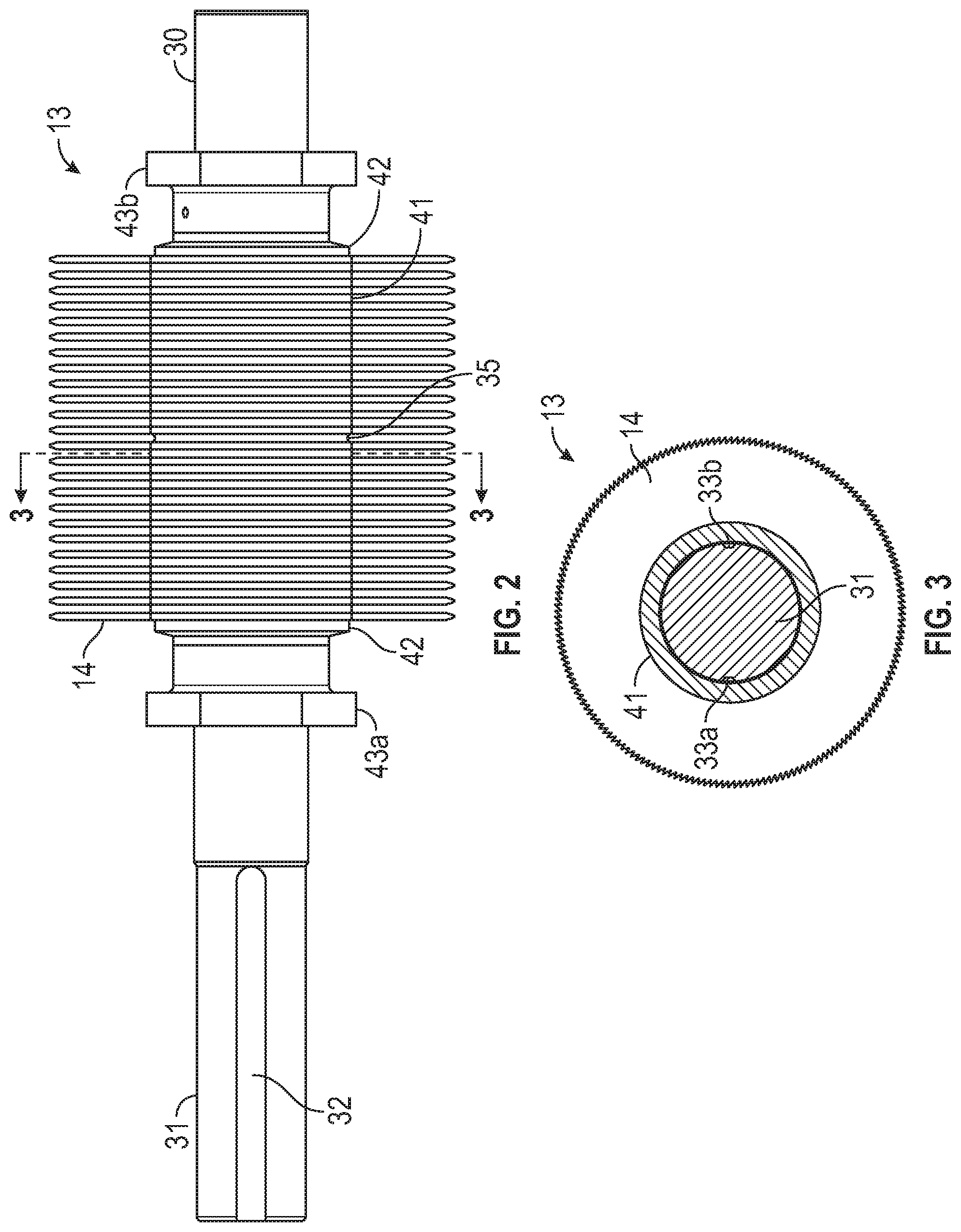
[0027] FIG. 2 is a side perspective view showing an exemplary prior art embodiment of a gin stand saw cylinder assembly.
[0028] FIG. 3 is a cross section view of the exemplary prior art embodiment of the gin stand saw cylinder assembly about the plane defined by line A-A of FIG. 2.
[0029] FIG. 4 is a perspective elevation view of a prior art driven shaft from the gin stand saw cylinder of FIGS. 1-3.
[0030] FIG. 5 is an end view of the prior art driven shaft from the gin stand saw cylinder of FIG. 4.
[0031] FIG. 6 is a front view of a prior art saw blade from the gin stand saw cylinder of FIGS. 1-3.
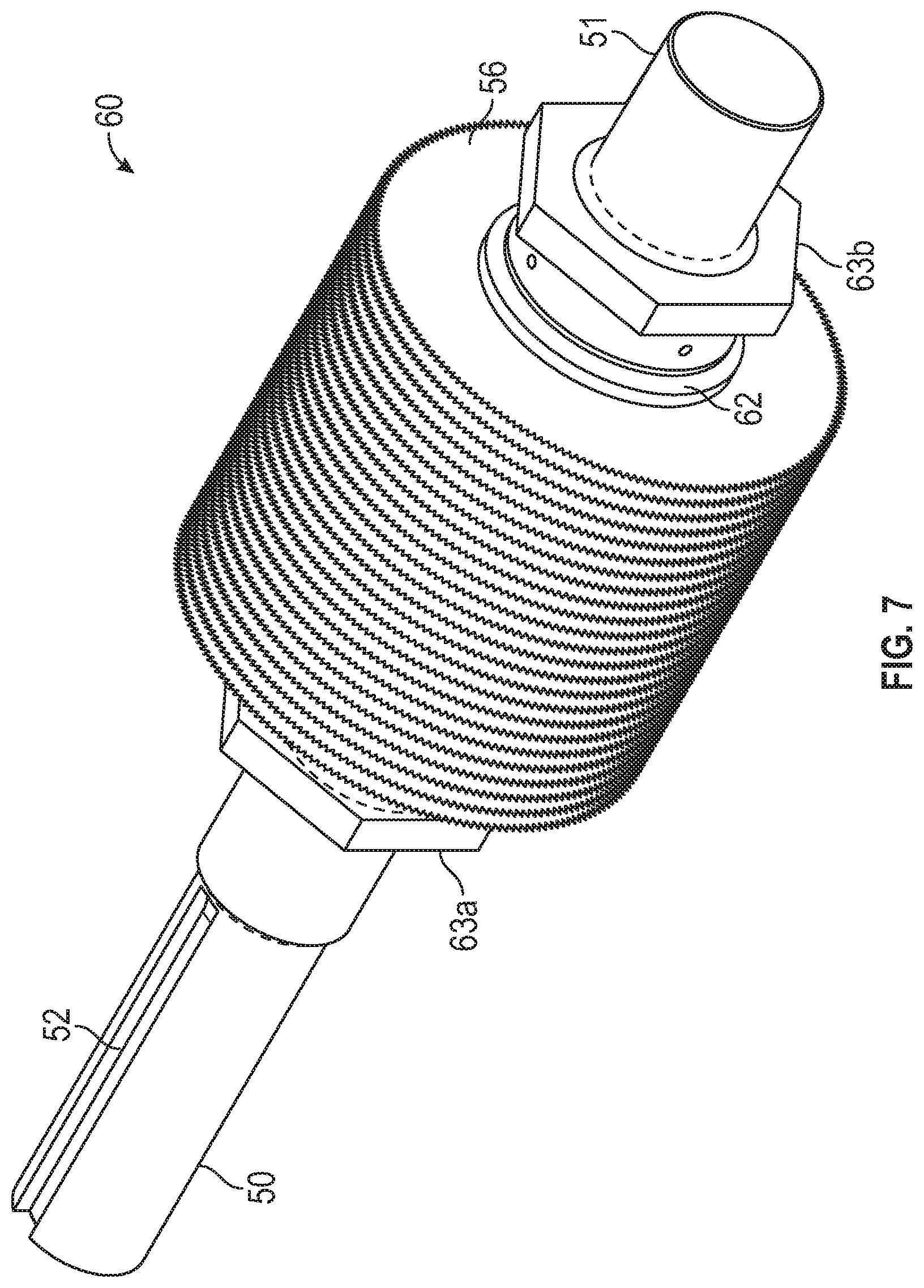
[0032] FIG. 7 is a perspective elevation view showing a first exemplary embodiment of an improved gin stand saw cylinder assembly of the present invention.
[0033] FIG. 8 is a side perspective view showing the first exemplary embodiment of the improved gin stand saw cylinder assembly of FIG. 7.
[0034] FIG. 9 is a cross section view of the first exemplary embodiment of the improved gin stand saw cylinder assembly about the plane defined by line A-A of FIG. 8.
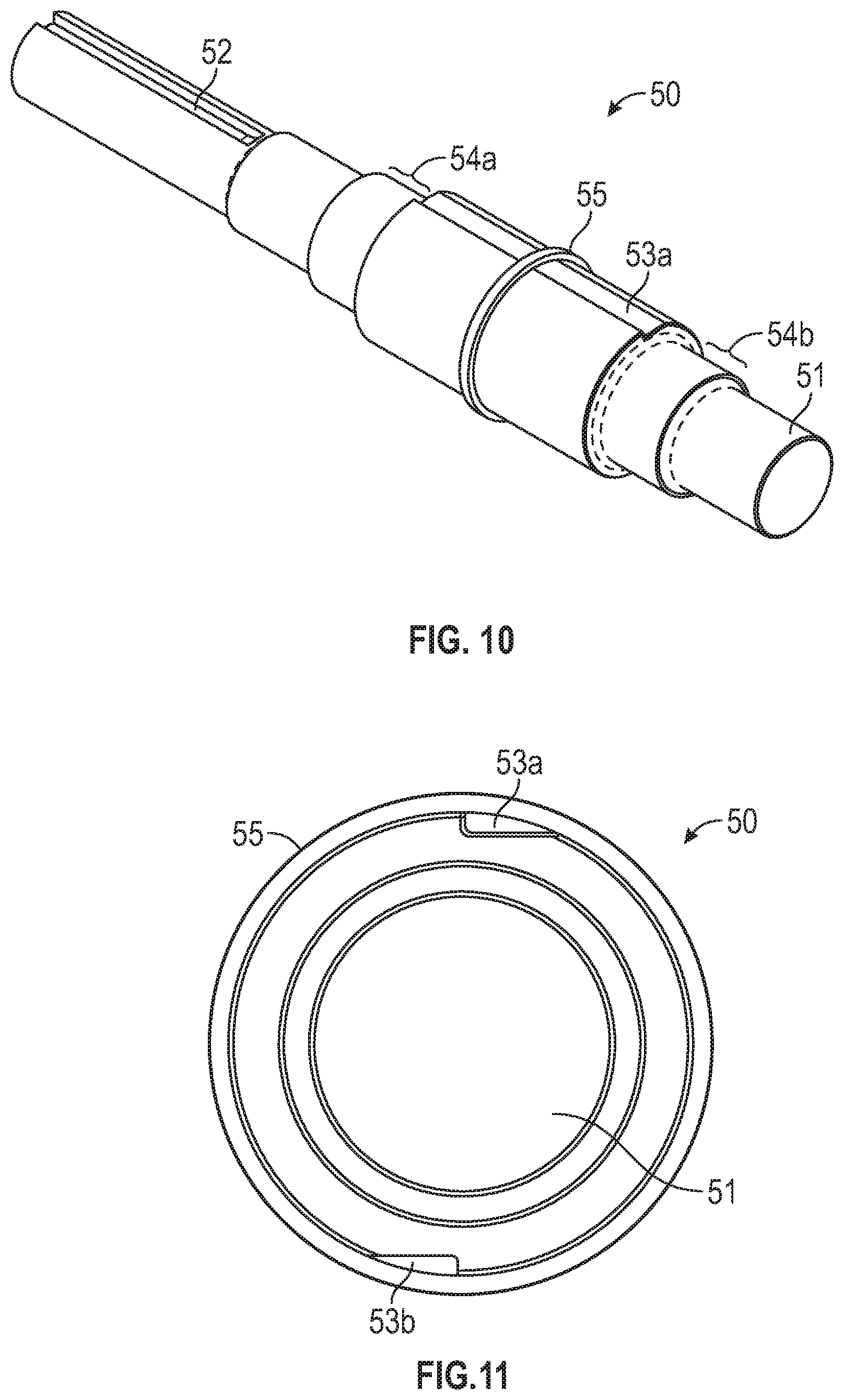
[0035] FIG. 10 is a perspective elevation view of an improved driven shaft from the improved gin stand saw cylinder assembly of FIGS. 7-9.
[0036] FIG. 11 is an end view of the improved driven shaft from the improved gin stand saw cylinder of FIG. 10.
[0037] FIG. 12 is a front view of an exemplary saw blade of the present invention shown separated from the gin stand saw cylinder of FIGS. 7-9.
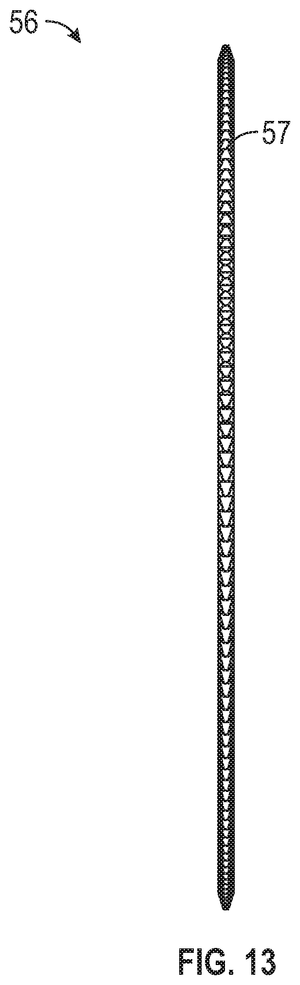
[0038] FIG. 13 is a bottom view or right-side view of the saw blade of FIG. 12.
[0039] FIG. 14 is a perspective elevation view showing a second exemplary embodiment of an improved gin stand saw cylinder assembly of the present invention.
[0040] FIG. 15 is a perspective elevation view of an exemplary improved driven shaft of the present invention separated from the improved gin stand saw cylinder assembly of FIG. 14.
[0041] FIG. 16 is an end view of the improved driven shaft from the improved gin stand saw cylinder of FIG. 14.
[0042] FIG. 17 is a perspective view of an exemplary saw blade of the present invention shown separated from a gin stand saw cylinder.
DETAILED DESCRIPTION OF PREFERRED EMBODIMENTS
[0043] For a further understanding of the nature, function, and objects of the present invention, reference should now be made to the following detailed description taken in conjunction with the accompanying drawings. While detailed descriptions of the preferred embodiments are provided herein, as well as the best mode of carrying out and employing the present invention, it is to be understood that the present invention may be embodied in various forms.
[0044] Exemplary embodiments of the present invention provide devices, systems, and methods for satisfying at least one of the following non-limiting objectives: [0045] to provide a practical and novel method by which to fix the inner diameter of a ginning saw blade relative to a driven saw shaft of a saw cylinder assembly, the saw cylinder assembly incorporated into a saw-type gin stand, the gin stand for separating cotton fiber from cotton seed, wherein the method prevents assembly errors and improves the consistency of the rotational balance of the final assembled product; [0046] to offer a saw cylinder assembly wherein a shape of a center hole of a saw blade and the complementary shape of a driven shaft preclude the possibility of the saw cylinder assembly from being assembled with some, or all, of the saw teeth orientated in the wrong direction; [0047] to present a saw-cylinder-assembly construction means for connecting a driven shaft to a saw blade, such that there is a directionality between the connection geometry of the saw blade and the driven shaft; and [0048] to disclose a symmetrical driven shaft, as compared to the prior art, such that the final saw cylinder assembly also is symmetrical, and not limited by a functional orientation (which requires a specific and limited directionality between the saw teeth of the final saw cylinder assembly and an end where a driving means for the shaft will be installed).
[0049] In order to optimize a saw gin stand's efficiency and effectiveness at separating cotton fiber from cotton seed, it may be beneficial for a gin stand to have aspects for better, more-consistent, and longer operations under prime mechanical conditions. It also may be beneficial for a saw cylinder assembly to have a user-interface that simplifies set-up, and that reduces the number and complexity of user-decisions/choices throughout the ginning process. Therefore, certain embodiments and aspects of the present invention provide a saw cylinder assembly comprising saw blades and a driven shaft, wherein the saw blades each, respectively, define a central aperture, and wherein the shape of the center aperture of the saw blade, and the complimentary shape of the shaft, preclude the possibility of a saw cylinder being assembled with some or all the saw teeth orientated in the wrong direction.
[0050] Certain embodiments of the present invention incorporate an asymmetrical tab or key defining the central aperture of the saw blades, wherein the key complements an asymmetrical keyway defined by the curved outer surface of the driven shaft. Similarly, other embodiments incorporate a symmetrical driven shaft, as compared to the prior art, wherein both ends of the shaft are similarly configured, such that it does not matter which end of the shaft is orientated in which direction within the saw cylinder assembly, and it does not matter which side of the shaft the saw blades are attached to, or in which direction the saw blades are flipped when attached.
[0051] The fundamental architecture of certain gin stands is shown in FIGS. 1-6. FIG. 1 shows an exemplary embodiment of a gin stand 10 comprises an inlet chute 11 wherein seed cotton enters the overall system in a single-locked or separated state, and at a controlled rate. The seed cotton is thrown by a picker roller 12 onto a gin saw cylinder 13, wherein an exemplary embodiment of a gin saw cylinder 13 is comprised of many spaced-apart circular saw blades 14 having teeth along their periphery and rotating about a common axis 15. The exemplary embodiment of the saw cylinder assembly 13 shown in FIGS. 2 and 3 comprises a driven shaft 30, a plurality of saw blades 14, a fixed center-spacer ring 35, slip-on spacer rings 41, bell washers 42, and nuts 43a and 43b.
[0052] FIG. 1 shows generally the manner in which each saw blade 14 pulls cotton fiber between the closely-spaced stationary ginning ribs 19, and pulls the fibers from the seed; the goal being to keep the fibers as long as possible. In practice, the teeth of each saw blade 14 are not sharpened in the same was as, for example, the leading edge of a blade, as the teeth are not meant to cut the fibers, but only to pull them from the seed. More specifically, the seed cotton is carried upward on the periphery of each saw blade 14 through the seed discharge shaft 16 into the lower portion of the roll box 17 directly below the oscillator cylinder 18. The plurality of saw blades 14 of the gin saw cylinder 13 rotate between the closely-spaced stationary ginning ribs 19, which serve to strip a portion of the cotton fibers from each seed as the saw teeth, and attached fibers, pass between the closely spaced ribs 19.
[0053] The partially ginned seeds are larger than the gap between the ginning ribs 19, and the processed material becomes part of a seed roll rotating around the axis of the oscillator cylinder 18. The fibers remaining on the partially ginned seed tend to keep the seeds loosely attached to the seed roll, which is a large mass made up of seeds with varying amounts of fiber remaining. Each seed will rotate around the roll box 17 a number of times until the seed no longer has enough fiber length attached to it to keep the seed adhered to the seed roll, at which time the seed falls out through the seed discharge shaft 16 and out of the bottom of the gin stand 10.
[0054] As the cotton fiber passes between the ginning ribs 19, the cotton fibers remain attached on the periphery of the saw blades 14 until the fibers are doffed-off of the saw teeth by a counter-rotating brush cylinder 20. As the surface speed of the brush cylinder 20 is greater than the tip-speed of the saw cylinder 13, the processed cotton fibers are lifted off of the teeth of each saw blade 14 and passed out of the machine through the lint outlet 21.
[0055] FIGS. 2 and 3 show a side perspective view of an exemplary prior art embodiment of a gin stand saw cylinder 13 assembly and a cross section view of an exemplary prior art embodiment of the gin stand saw cylinder 13 assembly about the plane defined by line A-A of FIG. 2, respectively. As can be seen in FIG. 2, the saw blades are spaced apart so as to rotate between the closely-spaced stationary ginning ribs 19, which serve to strip a portion of the cotton fibers from each seed as the saw teeth, and attached fibers, pass between the closely spaced ribs 19, as disclosed above.
[0056] FIGS. 4 and 5 show an exemplary embodiment of the driven shaft 30 comprising a shaft 31, a drive keyway 32 (to provide means for driving the shaft 31 with a belt-and-pulley, or similar means, for example), two saw blade keyways 33a and 33b, two threaded sections 34a and 34b, and a fixed center-spacer ring 35 that is permanently attached to the shaft 31. FIG. 6 shows an exemplary embodiment of a gin saw blade 14 having a plurality of directional saw teeth 37, a center hole 38, and a single tab or key 39, which is symmetrical about centerline y-y.
[0057] When the components shown in FIGS. 4-6 are assembled together, along with the other necessary components, for example, as is shown in FIG. 2, it becomes apparent to a person having ordinary skill in the art that the location of the fixed center-spacer ring 35 on the driven shaft 30 is critical to the alignment of the saw blades 14 for this particular embodiment, so each saw blade 14 will fall safely within the gaps between ribs 19, for example. It is for this reason that the center-spacer ring 35 usually is permanently and precisely attached to the shaft 31, as it serves as a point of reference for all the saw blades 14 and spacer rings 35 stacked on each end of the driven shaft 30, in certain embodiments. It is envisioned that the center spacer ring 35 may not be permanently attached.
[0058] It should be noted that, in certain exemplary embodiments, the driven shaft 30 has two saw blade keyways 33a, 33b situated 180 degrees apart, or antipodal, relative to one another, to help maintain rotational balance (for example, as is shown in FIG. 5). In contrast, the saw blade 14 only has a single tab or key 39. Historically, it has been difficult to machine the blade keyways 33a, 33b precisely and consistently 180 degrees apart, or antipodal, relative to one another. Even if the saw blade holes were manufactured with two tabs or keys 39, a person having ordinary skill in the art understands that there is a risk that the keyways 33a, 33b may not line-up with both tabs or keys 39, thus making assembly significantly difficult to impossible.
[0059] As a practical matter, the saw blades 14 have been manufactured with only one tab or key 39 to assure assembly will be possible. To help assure rotational balance of the driven shaft 30 will be preserved, each successive saw blade 14 is installed alternating with the tab or key 39 in either keyway 33a, 33b. As the saw blades 14 must be carefully stacked and lined up with gauges (for example, as is shown in FIG. 2), and as paper-thin shims sometimes must be inserted along the way in this process (for example, in between any pairing of a group consisting of the plurality of saw blades 14, the fixed center-spacer ring 35, the slip-on spacer rings 41, the bell washers 42, and the nuts 43a, 43b), and as the plurality of saw blades 14 must be individually tuned or straightened after the nuts 43a, 43b are installed, and as most modern gin stands commonly have from about 150 to 300 saw blades 14 on each driven shaft 30, the entire process of completing a finished saw cylinder assembly 13 can take many hours of skilled patient labor. One of ordinary skill in the art understands that correcting misalignments via shims is tedious, inexact, difficult, and time-consuming; and often times determining the number of shims needed may necessitate the saw cylinder assembly 13 being repeatedly removed, reassembled, replaced, and/or measured relative to the alignment reference point(s).
[0060] Currently, it is not unusual for an assembler of a saw cylinder assembly 13 to accidentally forget to rotate and/or alternate the saw blades 14 every time a saw blade 14 is stacked during the assembly process, which creates an imbalance that may not be discovered until the full gin stand 10 is assembled and run (for example, as is shown in FIG. 1). More specifically, as there is a directionality associated with the directional saw teeth 37, and as there is a center-spacer ring 35 defined along the shaft 31 of the driven shaft 30, and as one half of the saw cylinder 13 is stacked from a first end (relative to the fixed center-spacer ring 35) opposite, or distal to, a second end (the second end defining the drive keyway 32, for example), sometimes half the saw blades 14 are installed with the saw teeth 37 orientated in the opposite direction from the others. If this is not discovered until after final assembly of the gin stand 10, many hours will have been wasted, as the saw cylinder assembly 13 will need to be reworked.
[0061] Again, correcting these errors is tedious, difficult, and time-consuming. As such, embodiments and aspects of the present invention provide for (1) a novel saw cylinder assembly wherein the shape of the center hole of the saw and the complimentary shape of the shaft preclude the possibility of a saw cylinder assembly being assembled with some or all the saw teeth orientated in the wrong direction (2) whereby there is no possibility a saw cylinder can be assembled in such a way as to create a rotational imbalance.
[0062] Currently, it also is not unusual for an assembler of a saw cylinder assembly 13 to accidentally forget the functional direction of the driven shaft 30 when stacking the saw cylinder assembly 13, whether or not all of the individual saw blades 14 and their saw teeth 37 are consistently orientated correctly, or whether one or more is/are in the wrong orientation. In any event, this results in a completed saw cylinder assembly 13 that is substantially backwards to the functional-direction of a means for driving the driven shaft 30 (a belt-and-pulley, or similar means, for example).
[0063] More specifically, as the driven shaft 30 is commonly asymmetrical from one end to the other, and as the saw blades 14 usually must rotate in one direction in order for the ginning process to work, then by necessity there is a functional orientation required between the directionality of the saw teeth 37 and the end of the driven shaft 30 where the means for driving the shaft 30 is engaged. If this is not discovered until after final assembly of the gin stand 10, many hours will have been wasted, as the saw cylinder assembly 13 will need to be reworked.
[0064] Again, correcting these errors is tedious, difficult, and time-consuming; as such, embodiments and aspects of the present invention provide for a novel saw cylinder assembly construction with a means for connection to the driven shaft, such that there is a directionality associated with connection geometry between the saw blade and driven shaft. Said another way, embodiments and aspects of the present invention provide for a saw for use in a saw-type cotton gin stand constructed with a directional means for mounting the saw blades to the driven shaft, and provide a novel method for fixing the inner diameter of each saw blade relative to the shaft.
[0065] With this background in mind, exemplary embodiments of an improved gin stand and, in particular, an improved saw cylinder assembly will next be disclosed that achieve the above disclosed objectives and address the above disclosed difficulties of the prior art. While the newly disclosed embodiments share certain structural features with the exemplary gin saw of FIGS. 1-6, the distinctions and alterations will become apparent to one of ordinary skill in the art upon reading the following additional disclosure. The objects of the present invention may be achieved, at least in part, by providing a system for a saw cylinder assembly 60, at least two exemplary embodiments of which are shown in FIGS. 7-13.
[0066] FIGS. 7-9 show a first exemplary embodiment of an improved saw cylinder assembly 60. The first exemplary embodiment comprises a driven shaft 50, a plurality of saw blades 56, a fixed center-spacer ring 55, slip-on spacer rings 61, bell washers 62, and nuts 63a, 63b.
[0067] FIGS. 10-11 show an exemplary embodiment of an improved driven shaft 50 comprising a shaft 51, a drive keyway 52 (to provide means for driving the shaft 51 with a belt-and-pulley, or similar means, for example), two directional saw blade keyways 53a, 53b, two threaded sections 54a, 54b, and a fixed center-spacer ring 55 that is permanently attached to the shaft 51.
[0068] FIG. 12 shows an exemplary embodiment of the gin saw blade 56 comprising a plurality of directional saw teeth 57, a center hole 58, and two directional tabs or keys 59a and 59b, which are asymmetrical about centerline y'-y'.
[0069] For this particular first embodiment, the location of the fixed center-spacer ring 55 on the driven shaft 50 is critical to the alignment of the saw blades 56 so each will fall safely within the gaps between ribs 19. It is for this reason the center-spacer ring 55 is permanently and precisely attached to the shaft 51, as it serves as a point of reference for all the saws blades 56 and spacer rings 61 stacked on each end of the shaft 50.
[0070] It should be noted that the driven shaft 50 has, as a non-limiting example, two saw blade keyways 53a, 53b situated by about 180 degrees apart, or antipodal, relative to one another, to help maintain rotational balance. Each saw blade 56 has, as a non-limiting example, two directional tabs 59a, 59b which are complementary to the shape of the keyways 53a, 53b.
[0071] In this way, the first exemplary embodiment of the improved saw cylinder assembly provides a directionality associated with the saw teeth 57 and the asymmetrical tabs 59a, 59b, and provides a fixed relationship between the orientation of the saw teeth 57 and the tabs 59a, 59b. As a practical matter, each saw blade 56 need not be installed in alternate (e.g., with the tab 39, in either keyway 33a or 33b, as in the earlier described embodiment). As such, the present invention provides for a more accurate, efficient, and effective setup of the saw cylinder assembly 60, thereby reducing the possibility of user-errors during the aligning and positioning of the plurality of saw blades 56.
[0072] More specifically, for this first exemplary embodiment, as asymmetrical keyways 53a, 53b are complementary in shape to the tabs 59a, 59b defined by each saw blade 56, and as the saw blades 56 may be rotated in only one direction in order for the ginning process to work, then the possibility for assembling some or all of the saw blades 56 with the saw teeth 57 oriented in a direction antithetical to the rotation-direction of the shaft 51, when driven, has been significantly mitigated or eliminated. In addition, the possibility for assembling the saw blades 56 in such a way as to create a rotational imbalance has been significantly mitigated or eliminated.
[0073] FIGS. 14-16 show a second exemplary embodiment of an improved saw cylinder assembly 160 wherein the driven shaft 150 is symmetrical from one end to the other end. The second exemplary embodiment is similarly structured and composed as the first exemplary embodiment, except for the symmetry and the differences presented herein.
[0074] Like the first exemplary embodiment of FIGS. 7-13, the second exemplary embodiment shown in FIG. 14 comprises a driven shaft 150, a plurality of saw blades 156, a fixed center-spacer ring 155, slip-on spacer rings 161, bell washers 162, and nuts 163a, 163b. An exemplary embodiment of the improved driven shaft 150 is shown in FIGS. 15-16.
[0075] For this particular second embodiment, the driven shaft 150 defines a shaft 151, a drive keyway 152a, 152b on either side of the driven shaft 150 (to provide means for driving the shaft 151 with a belt-and-pulley, or similar means, for example, for either side), two directional saw blade keyways 153a, 153b, two threaded sections 154a, 154b, and a fixed center-spacer ring 155 that is permanently attached to the shaft 151. An exemplary embodiment of the gin saw blade 156 is shown as in FIG. 12 and presented as gin saw blade 56.
[0076] In this way, the second exemplary embodiment of the improved saw cylinder assembly still provides a directionality associated with the saw teeth 57 and the asymmetrical tabs 59a, 59b, and provides a fixed relationship between the orientation of the saw teeth 57 and the tabs 59a, 59b (like the first exemplary embodiment above), but regardless of which end of the driven shaft 150 the saw blades 156 are stacked on to. Again, as a practical matter, each saw blade 156 need not be installed in alternate.
[0077] Returning once more to the practical matters, it is not unusual for an assembler of a saw cylinder assembly 13 to accidentally forget the functional direction of a standard driven shaft 30, when stacking the saw cylinder assembly 13. As such, the second exemplary embodiment provides for a more accurate, efficient, and effective setup of the saw cylinder assembly 160, via a driven shaft 160 that is symmetrical from one end to the other. Regardless of the saw blades 14 having to rotate in one direction, in order for the ginning process to work, and regardless of the necessitated functional-orientation required between the directionality of the saw teeth 37, the saw cylinder assembly 160 is not limited to having only one end of the driven shaft 150 where the means for driving the shaft 151 must be engaged.
[0078] It is envisioned that, in certain exemplary embodiments of the improved driven shaft 150, the shaft 150 is driven from both ends via the drive keyways 152a, 152b using any means for driving known to a person having ordinary skill in the art, including mechanical means and electro/magnetic means.
[0079] Thus, an embodiment of the present invention disclosed above is a saw cylinder assembly similar to the embodiment shown in FIGS. 7 and 8. Specifically, an embodiment of the present invention disclosed above is a saw cylinder assembly 60 for a gin stand 10, as shown in FIG. 1, comprising a driven shaft 50 and a plurality of directional saw blades 56. The drive shaft 50 comprises a shaft 51 defining a means for engaging with a driving source 52, on one end of the shaft 51, and at least two directional saw blade keyways 53a, 53b, as shown in FIGS. 9-11, wherein each of the at least two directional saw blade keyways 53a, 53b is an asymmetrical longitudinally-extending superficial groove on a central length of the shaft 51. The directional saw blades 56, as shown in FIGS. 12 and 13, each comprise a central aperture 58 comprising at least two directional keys 59a, 59b and a plurality of teeth 57 defined along the outer-periphery of each saw blade 56. The at least two directional keys 59a, 59b are complementary in number, shape, and position, to the at least two directional saw blade keyways 53a, 53b of the driven shaft 50, for mating. The plurality of teeth 57 have a preferred direction for function.
[0080] When assembled, as shown in FIGS. 7 and 8, the plurality of directional saw blades 56 are mated with the driven shaft 50 in only one orientation, and the plurality of teeth 57 rotate about a common axis defined by the driven shaft 50. The complementary number, shape, and position of the at least two directional keys 59a, 59b with the at least two directional saw blade keyways 53a, 53b preclude the saw cylinder assembly 60 from being assembled with any of the plurality of teeth 57 being orientated against the preferred direction for function.
[0081] Another embodiment of the present invention is a saw cylinder assembly similar to the embodiment shown in FIGS. 7 and 8. Specifically, an embodiment of the present invention disclosed above is a saw cylinder assembly 60 for a saw-type gin stand 10, as shown in FIG. 1, comprising an asymmetrical driven shaft 50 and a plurality of directional saw blades 56. The asymmetrical driven shaft 50 comprises a shaft 51 comprising a means for engaging with a driving source 52, on one end of the shaft 51, and two directional saw blade keyways 53a, 53b, as shown in FIGS. 9-11, wherein each of the two directional saw blade keyways 53a, 53b is an asymmetrical longitudinally-extending superficial groove on a central length of the shaft 51, the two superficial grooves positioned antipodal about the shaft 50, as shown in FIGS. 9 and 11. The plurality of directional saw blades 56 are circular and each comprises a central aperture 58, as shown in FIGS. 12 and 13, comprising two directional keys 59a, 59b and a plurality of teeth 57 defined along the outer-periphery of each blade 56. The two directional keys 59a, 59b are complementary in shape and position to the two directional saw blade keyways 53a, 53b of the driven shaft 50, for mating, and the plurality of teeth 57 have a preferred direction for function. When assembled, as shown in FIGS. 7 and 8, the plurality of directional saw blades 56 are mated with the driven shaft 50 in only one orientation, and the plurality of teeth 57 rotate about a common axis defined by the driven shaft 50. The complementary shape and position of the two directional keys 59a, 59b with the two directional saw blade keyways 53a, 53b preclude the saw cylinder assembly 60 from being assembled with any of the plurality of teeth 57 being orientated against the preferred direction for function.
[0082] Yet another embodiment of the present invention is a saw cylinder assembly similar to the embodiment shown in FIG. 14. Specifically, an embodiment of the present invention disclosed above is a saw cylinder assembly 160 for a gin stand 10, as shown in FIG. 1, comprising a symmetrical driven shaft 150 and a plurality of directional saw blades 156. The symmetrical driven shaft 150 comprises a shaft 151 defining two means for each, respectively, engaging with a driving source 152a, 152b, as shown in FIG. 16, one on one end of the shaft and another on the other end of the shaft, and two directional saw blade keyways 53a, 53b, as shown in FIGS. 15 and 16. Each of the two directional saw blade keyways 53a, 53b is an asymmetrical longitudinally-extending superficial groove on a central length of the shaft 151, between the two ends, the two superficial grooves positioned antipodal about the shaft 151, as shown in FIGS. 15 and 16. The plurality of directional saw blades 156, as shown in FIG. 17, are circular and each comprises a central aperture 158 comprising two directional keys 159a, 159b and a plurality of teeth 157 defined along the outer-periphery of each blade 156. The two directional keys 159a, 159b are complementary in shape and position to the two directional saw blade keyways 153a, 153b of the driven shaft 150, for mating, and the plurality of teeth 157 have a preferred direction for function. When assembled, as shown in FIG. 14, the plurality of directional saw blades 156 are mated with the driven shaft 150 in only one orientation, and the plurality of teeth 157 rotate about a common axis defined by the driven shaft 150. The complementary shape and position of the two directional keys 159a, 159b the two directional saw blade keyways 153a, 153b preclude the saw cylinder assembly 160 from being assembled with any of the plurality of teeth 157 being orientated against the preferred direction for function
[0083] It is envisioned that the number of directional asymmetrical tabs in each saw blade disclosed herein, and the number of corresponding directional asymmetrical keyways, is not limited to a quantity of two to adhere to the spirit of the current invention. It also is envisioned that the exact shape and geometry as presented herein and in the figures does not constitute the only shape of a saw blade tab(s) or key(s) and of the concomitant shape of the shaft keyway(s) required to adhere to the spirit of the current invention.
[0084] For the sake of clarity, it should be noted that many of the figures herein show shorter shafts and fewer saw blades than are typically used in current commercial gin stands. It should also be noted the saw tooth profiles in the figures have been enlarged and the shape simplified and adjusted, as has the ratio of the blade diameter to the material thickness. In particular, it is envisioned that embodiments of the present invention, in particular, the saw cylinder assembly, may come in various widths, including but not limited to about 8.0 feet, 10.0 feet, and 12.0 feet width embodiments (referred, more specifically, as the distance from the outside saw blade on one far end of a saw cylinder assembly to the outside saw blade on the other end).
[0085] It also is envisioned that embodiments of the individual saw blades may come in various diameters, including but not limited to about 8.0 inches, 9.0 inches, 12.0 inches, 16.0 inches, or 18.0 inches in diameter embodiments, and embodiments having a thickness of about 0.036 inches or 0.045 inches.
[0086] The various embodiments are provided by way of example and are not intended to limit the scope of the disclosure. The described embodiments comprise different features, not all of which are required in all embodiments of the disclosure. Some embodiments of the present disclosure utilize only some of the features or possible combinations of the features. Variations of embodiments of the present disclosure that are described, and embodiments of the present disclosure comprising different combinations of features as noted in the described embodiments, will occur to persons with ordinary skill in the art. It will be appreciated by persons with ordinary skill in the art that the present disclosure is not limited by what has been particularly shown and described herein above. Rather the scope of the invention is defined by the appended claims.
* * * * *
D00000
D00001
D00002
D00003
D00004
D00005
D00006
D00007
D00008
D00009
D00010
D00011
D00012

D00013

XML
uspto.report is an independent third-party trademark research tool that is not affiliated, endorsed, or sponsored by the United States Patent and Trademark Office (USPTO) or any other governmental organization. The information provided by uspto.report is based on publicly available data at the time of writing and is intended for informational purposes only.
While we strive to provide accurate and up-to-date information, we do not guarantee the accuracy, completeness, reliability, or suitability of the information displayed on this site. The use of this site is at your own risk. Any reliance you place on such information is therefore strictly at your own risk.
All official trademark data, including owner information, should be verified by visiting the official USPTO website at www.uspto.gov. This site is not intended to replace professional legal advice and should not be used as a substitute for consulting with a legal professional who is knowledgeable about trademark law.