Method For Producing A Steel Component Having A Metal Coating Protecting It Against Corrosion
Banik; Janko ; et al.
U.S. patent application number 16/647894 was filed with the patent office on 2020-07-09 for method for producing a steel component having a metal coating protecting it against corrosion. The applicant listed for this patent is ThyssenKrupp Steel Europe AG ThyssenKrupp AG. Invention is credited to Janko Banik, Maria Koyer, Dirk Rosenstock, Manuela Ruthenberg.
| Application Number | 20200216925 16/647894 |
| Document ID | / |
| Family ID | 64332260 |
| Filed Date | 2020-07-09 |


| United States Patent Application | 20200216925 |
| Kind Code | A1 |
| Banik; Janko ; et al. | July 9, 2020 |
METHOD FOR PRODUCING A STEEL COMPONENT HAVING A METAL COATING PROTECTING IT AGAINST CORROSION
Abstract
A method for producing a steel component from a flat steel sheet is provided. The produced steel component includes a substrate and a coating. The method ensures that the steel component has an H.sub.diff content below a certain level. The low H.sub.diff content minimizes the risk of hydrogen-induced cracking of the steel component after hot forming, including during subsequent use of the steel component. The H.sub.diff content in the hot-formed steel component is ensured to be below a certain level by selecting furnace parameters depending on the rolling degree and the sheet thickness of the flat steel sheet.
| Inventors: | Banik; Janko; (Altena, DE) ; Koyer; Maria; (Dortmund, DE) ; Rosenstock; Dirk; (Essen, DE) ; Ruthenberg; Manuela; (Dortmund, DE) | ||||||||||
| Applicant: |
|
||||||||||
|---|---|---|---|---|---|---|---|---|---|---|---|
| Family ID: | 64332260 | ||||||||||
| Appl. No.: | 16/647894 | ||||||||||
| Filed: | October 11, 2018 | ||||||||||
| PCT Filed: | October 11, 2018 | ||||||||||
| PCT NO: | PCT/EP2018/077692 | ||||||||||
| 371 Date: | March 17, 2020 |
| Current U.S. Class: | 1/1 |
| Current CPC Class: | C22C 38/02 20130101; C22C 38/26 20130101; C21D 7/13 20130101; C21D 8/0405 20130101; C22C 38/22 20130101; C22C 38/28 20130101; C22C 38/04 20130101; C23C 2/28 20130101; C21D 1/76 20130101; C25D 7/0614 20130101; B21D 22/022 20130101; C21D 6/008 20130101; C22C 38/32 20130101; C21D 9/48 20130101; C23C 2/40 20130101; C21D 6/005 20130101; C21D 9/46 20130101; C23C 2/12 20130101; C21D 1/673 20130101; C21D 8/0426 20130101; C22C 38/002 20130101; C23C 2/06 20130101; C22C 38/06 20130101; C21D 6/002 20130101; C22C 38/001 20130101; B21D 22/208 20130101 |
| International Class: | C21D 9/48 20060101 C21D009/48; C21D 8/04 20060101 C21D008/04; C21D 6/00 20060101 C21D006/00; C23C 2/06 20060101 C23C002/06; C23C 2/40 20060101 C23C002/40; C23C 2/28 20060101 C23C002/28; C22C 38/32 20060101 C22C038/32; C22C 38/28 20060101 C22C038/28; C22C 38/26 20060101 C22C038/26; C22C 38/22 20060101 C22C038/22; C22C 38/06 20060101 C22C038/06; C22C 38/04 20060101 C22C038/04; C22C 38/02 20060101 C22C038/02; C22C 38/00 20060101 C22C038/00; B21D 22/02 20060101 B21D022/02 |
Foreign Application Data
| Date | Code | Application Number |
|---|---|---|
| Oct 19, 2017 | DE | 10 2017 218 704.2 |
Claims
1. A method for producing a steel component having a content of diffusible hydrogen H.sub.diff of up to 0.4 ppm, the method comprising the steps of: (A) providing a flat steel product having a coating including, in weight percent (wt. %), 3 to 15 Si, 1 to 3.5 Fe, 0.05 to 5.0 alkali and/or alkaline earth metals, remainder Al and unavoidable impurities, the flat steel product having a rolling degree to sheet thickness ratio (WGB) of greater than 0.8 to 200, (B) determining a hydrogen-related furnace parameter value (WOP value) for the flat steel product on the basis of the rolling degree to sheet thickness ratio (WGB) within a surface spanned by straight connecting paths between points P11 (WGB 0.8, WOP 100) and P13 (WGB 0.8, WOP 800), P13 (WGB 0.8, WOP 800) and P21 (WGB 26, WOP 650), P21 (WGB 26, WOP 650) and P41 (WGB 74, WOP 590), P41 (WGB 74, WOP 590) and P53 (WGB 150, WOP 520), P53 (WGB 150, WOP 520) and P51 (WGB 150, WOP 100) and P51 (WGB 150, WOP 100) and P11 (WGB 0.8, WOP 100) in a coordinate system in which the WOP value is plotted on the y axis and the rolling degree to sheet thickness ratio (WGB) is plotted on the x axis, (C) treating the flat steel product at an average furnace temperature T.sub.furnace (in K) for a duration t.sub.furnace (in h), wherein the dew point temperature of the furnace atmosphere of the furnace T.sub.dew point (in K), the average furnace temperature T.sub.furnace (in K) and the duration t.sub.furnace (in h) being set according to the following equation of general formula (1) WOP = T furnace K log ( t furnace h + 1.15 ) + ( T dew point K - 2 4 3 . 1 5 ) 1.6 , ( 1 ) ##EQU00007## and (D) forming the heated flat steel product from step (B) in a mold while being simultaneously cooled to obtain the steel component.
2. The method according to claim 1, wherein the WOP value is determined according to step (B) within a surface spanned by straight connecting lines between the points P12 (WGB 0.8, WOP 300) and P13 (WGB 0.8, WOP 800), P13 (WGB 0.8, WOP 800) and P21 (WGB 26, WOP 650), P21 (WGB 26, WOP 650) and P41 (WGB 74, WOP 590), P41 (WGB 74, WOP 590) and P53 (WGB 150, WOP 520), P53 (WGB 150, WOP 520) and P52 (WGB 150, WOP 200), P52 (WGB 150, WOP 200) and P32 (WGB 50, WOP 200), P32 (WGB 50, WOP 200) and P33 (WGB 50, WOP 300) and P33 (WGB 50, WOP 300) and P12 (WGB 0.8, WOP 300) in a coordinate system in which the WOP value is plotted on the y axis and the rolling degree to sheet thickness ratio (WGB) is plotted on the x axis.
3. The method according to claim 1, wherein the flat steel product includes, in wt. %): 0.06 to 0.50 C, 0.50 to 3.0 Mn, 0.10 to 0.50 Si, 0.01 to 1.00 Cr, up to 0.20 Ti, up to 0.10 Al, up to 0.10 P, up to 0.1 Nb, up to 0.01 N, up to 0.05 S and up to 0.1 B, remainder Fe and unavoidable impurities.
4. The method according to claim 1, wherein t.sub.furnace is 0.05 to 0.5 h.
5. The method according to claim 1, wherein the flat steel product is a blank made of a hot rolled strip or a blank made of a cold rolled strip.
6. The method according to claim 1, wherein step (A) includes coating the flat steel product with the coating by hot-dip galvanizing, by an electrolytic coating or by means of a piecework-coating process.
7. The method according to claim 1, wherein the coating is a double sided coating with a coating weight of 20 to 240 g/m.sup.2.
8. The method according to claim 1, wherein step (D) takes place at a cooling rate of from 10 to 500 K/s, preferably above 27 K/s.
9. The method according to claim 1, wherein the content of diffusible hydrogen H.sub.diff is 0.1, 0.2, 0.3 or 0.4 ppm in the material after hot forming.
10. A steel component comprising: a substrate including, by weight percentage (wt. %): 0.06 to 0.50 C, 0.50 to 3.0 Mn, 0.10 to 0.50 Si, 0.01 to 1.00 Cr, up to 0.20 Ti, up to 0.10 Al, up to 0.10 P, up to 0.1 Nb, up to 0.01 N, up to 0.05 S, and up to 0.1 B, remainder Fe and unavoidable impurities, a coating including, by wt. %; 3 to 15 Si, 1 to 3.5 Fe, 0.05 to 5.0 alkali and/or alkaline earth metals, remainder Al and unavoidable impurities.
11. The steel component according to claim 10, wherein the coating is a double sided coating with a coating weight of 20 to 240 g/m.sup.2.
12. The steel component according to claim 10, further comprising a fully alloyed alloy layer in a thickness of from 5 to 60 .mu.m.
13. A method of using the coated steel component according to claim 10, including incorporating the coated steel component as a bumper support/reinforcement, door reinforcement, B-pillar reinforcement, A-pillar reinforcement, roof frame or body sill.
14. The steel component according to claim 10, wherein the substrate includes, by wt. %: 0.06 to 0.50 C, 0.50 to 3.0 Mn, 0.10 to 0.50 Si, 0.01 to 1.00 Cr, up to 0.20 Ti, 0.01 to 0.05 Al, 0.00 to 0.05 P, 0.001 to 0.1 Nb, up to 0.01 N, 0.00 to 0.005 S and 0.001 to 0.05 B, remainder Fe and unavoidable impurities.
15. The steel component according to claim 10, wherein the substrate includes, by wt. %: 0.06 to 0.50 C, 0.50 to 3.0 Mn, 0.10 to 0.50 Si, 0.01 to 1.00 Cr, up to 0.20 Ti, 0.02 to 0.05 Al, 0.00 to 0.02 P, 0.001 to 0.1 Nb, up to 0.01 N, 0.00 to 0.003 S and 0.002 to 0.0035 B, remainder Fe and unavoidable impurities.
Description
TECHNICAL FIELD
[0001] The present invention relates to a method for producing a steel component comprising a substrate and a coating, to a corresponding steel component, and to the use thereof in the automotive sector.
TECHNICAL BACKGROUND
[0002] In order to provide the combination of low weight, maximum strength and protective effect required in modern car body construction, nowadays components which are hot-formed from high-strength steels are used in the regions of the body which may be subject to particularly high loads in the event of a crash. In hot forming, also called hot stamping, steel blanks which were previously separated from a cold-rolled or hot-rolled steel strip are heated to a forming temperature that is generally above the austenitizing temperature of the steel in question and are placed into the mold of a forming press in the heated state. Over the course of the subsequent forming, the sheet metal blank or the component formed therefrom undergoes rapid cooling due to the contact with the cool mold. The cooling rates are set such that a tempered microstructure results in the component.
[0003] WO 2015/036151 A1 discloses a method for producing a steel component provided with a metal, corro-sion-protective coating and a corresponding steel component. The method according to this document comprises coating a flat steel product with an alloy of aluminum, zinc, magnesium and optionally silicon and iron, cutting a blank from the flat steel product, heating the blank and forming the blank to obtain the desired steel component.
[0004] DE 699 07 816 T2 discloses a method for producing a coated hot-rolled and cold-rolled steel sheet having very high strength after thermal treatment. For this purpose, a flat steel product is provided with a coating and is thermally treated. During the thermal treatment, the workpiece is heated to a temperature of over 750.degree. C.
[0005] EP 2 993 248 A1 discloses a flat steel product having an aluminum-containing coating, which contains from 0.005 to 0.7 wt. % of at least one alkali and/or alkaline earth metal, and a method for its production. In this method, the coated flat steel product is heated to a temperature of from 700 to 900'C for 360 s, 600 s or 800 s and is then formed.
[0006] When heating the sheet metal blanks, consisting of a steel substrate and an aluminum-based, metal cor-rosion-protection coating, hydrogen diffuses into the steel substrate through the metal coating due to the surface reaction of the moisture present in the furnace with the aluminum coating. After press-hardening, the hydrogen can no longer escape from the steel substrate since the metal coating is a barrier to the diffusible hydrogen H.sub.diff at room temperature. The content of H.sub.diff reduces the stresses which can be per-manently borne by the steel, and spontaneous "hydrogen-induced" fractures can occur if tensile stresses are present in the sheet metal. In order to avoid cracks at the stresses that are usually present in the body-in-white construction, the content of diffusible hydrogen should be below a component-specific value. This value depends, inter alia, on the complexity of the hot-forming operation, the post-processing by, for example, laser cutting, punching, mechanical cutting or hot trimming and the installation situation and joining concept and thus the state of tension in the bodywork. The amount H.sub.diff remaining after processing should preferably be .ltoreq.0.4 ppm (parts per million) prior to critical body-in-white processes, depending on said processing.
[0007] Furthermore, there are manufacturing processes in which regions of coated steel strips are rolled to a lower sheet thickness than other regions and corresponding sheet metal blanks having different rolling degrees are then taken therefrom. As a result, weight-optimized and load-adapted components can be produced. The ratio of the decrease in thickness due to rolling to the starting thickness is referred to as the rolling degree. In this case, according to the invention, the rolling degree applies only to a rolling process in which the coating is already present on the substrate. The rolled regions having a lower sheet thickness compared with the sheet thickness existing prior to rolling have a significantly higher defect density in the steel substrate due to the rolling. As a result, diffusible hydrogen can accumulate to a greater degree in the rolled regions than in the non-rolled regions, such that, after the hot forming and the press hardening, there is a higher diffusible hydrogen content. As a result, hydrogen-induced cracking can occur much more rapidly after hot forming and press hardening in material that is rolled after coating. A known method for reducing the content of diffusible hydrogen in the component is to lower the dew point in the furnace by the steel sheet being heated before forming, in order to thus prevent the formation of diffusible hydrogen from the existing moisture in the furnace atmosphere during the oxidation of the substrate and as a result to lower the Hei absorption by the steel component. Lowering the dew point is, however, more complex the lower the dew point needs to be. It is therefore desirable to not influence the dew point as much as possible and, if required, to not lower it too much.
[0008] The problem addressed by the present invention is therefore to provide a method for producing steel components comprising a substrate and a coating by means of which corresponding steel components can be obtained which have the lowest possible H.sub.diff content in order to minimize the risk of hydrogen-induced cracking after hot forming and to minimize said risk in subsequent use. Furthermore, the problem addressed by the present invention is to provide a method by means of which it is possible not to exceed a certain H.sub.diff content in a hot-formed component by selecting different furnace parameters depending on the rolling degree and the sheet thickness of the flat steel product used.
[0009] This problem is solved by the method according to the invention for producing a steel component having a content of diffusible hydrogen H.sub.diff of up to 0.4 ppm, comprising at least the steps of: [0010] (A) providing a flat steel product having a coating containing (all data in wt. %) 3 to 15 Si, 1 to 3.5 Fe, 0.05 to 5.0 alkali and/or alkaline earth metals, remainder Al and unavoidable impurities, which has a rolling degree to sheet thickness ratio (WGB) of 0.8 to 200, [0011] (B) determining a WOP value on the basis of the rolling degree to sheet thickness ratio WGB within a surface spanned by straight connecting paths between the points P11 (WGB 0.8, WOP 100) and P13 (WGB 0.8, WOP 800), P13 (WGB 0.8, WOP 800) and P21 (WGB 26, WOP 650), P21 (WGB 26, WOP 650) and P41 (WGB 74, WOP 590), P41 (WGB 74, WOP 590) and P53 (WGB 150, WOP 520), P53 (WGB 150, WOP 520) and P51 (WGB 150, WOP 100) and P51 (WGB 150, WOP 100) and P11 (WGB 0.8, WOP 100) in a coordinate system in which the WOP value is plotted on the y axis and the rolling degree to sheet thickness ratio is plotted on the x axis, as preferably shown in FIG. 1, [0012] (C) treating the flat steel product at an average furnace temperature T.sub.furnace (in Kelvins (K)) for a duration t.sub.furnace (in hours (h)), wherein the dew point temperature of the furnace atmosphere of the furnace T.sub.dew point (in Kelvins (K)), the average furnace temperature T.sub.furnace (In K) and the duration t.sub.furnace (in h) are set according to the following equation of general formula (1)
[0012] WOP = T furnace K log ( t furnace h + 1.15 ) + ( T dew point K - 2 4 3 . 1 5 ) 1.6 , ( 1 ) ##EQU00001## [0013] and [0014] (D) forming the heated flat steel product from step (B) in a mold while being simultaneously cooled to obtain the steel component.
[0015] Furthermore, these problems are also solved by a corresponding steel component and by the use of the steel component according to the invention in the automotive sector, in particular as a bumper sup-port/reinforcement, door reinforcement, B-pillar reinforcement, A-pillar reinforcement, roof frame or body sill.
[0016] The method according to the invention will be described in detail below.
[0017] The method according to the invention serves to produce a steel component having a content of diffusible hydrogen H.sub.diff of up to 0.4 ppm, preferably 0.01 to 0.4 ppm, particularly preferably 0.05 to 0.4 ppm, for example 0.1, 0.2, 0.3, or 0.4 ppm, in the material after hot forming in each case. Hat describes the amount of hydrogen atoms present in dissolved form in the steel substrate after hot forming. Methods for determining the H.sub.diff content are known per se to a person skilled in the art, for example desorption mass spectrometry using heated samples (thermal desorption mass spectrometry (TDMS)).
[0018] Step (A) of the method according to the invention comprises providing a flat steel product having a coating containing (all data in wt. %) 3 to 15 Si, 1 to 3.5 Fe, 0.05 to 5.0 alkali and/or alkaline earth metals, remainder Al and unavoidable impurities, which has a rolling degree to sheet thickness ratio of greater than 0.8 to 200.
[0019] According to the invention, in step (A) of the method according to the invention, any flat steel product which appears suitable to a person skilled in the art and has a corresponding coating can be used. According to the invention, a flat steel product containing the following is preferably used in the method according to the invention (all data in wt. %)
[0020] 0.06 to 0.50, preferably 0.18 to 0.37, particularly preferably 0.20 to 0.25 C,
[0021] 0.50 to 3.0, preferably 0.80 to 2.00, particularly preferably 1.00 to 1.60 Mn,
[0022] 0.10 to 0.50, preferably 0.15 to 0.40, particularly preferably 0.20 to 0.30 Si,
[0023] 0.01 to 1.00, preferably 0.10 to 0.5, particularly preferably 0.10 to 0.40 Cr,
[0024] up to 0.20, preferably 0.01 to 0.10, particularly preferably 0.01 to 0.05 Ti,
[0025] up to 0.10, preferably 0.01 to 0.05, particularly preferably 0.02 to 0.05 Al,
[0026] up to 0.10, preferably 0.00 to 0.05, particularly preferably 0.00 to 0.02 P,
[0027] up to 0.1, preferably 0.001 to 0.1 Nb,
[0028] up to 0.01 N,
[0029] up to 0.05, preferably 0.00 to 0.005, particularly preferably 0.00 to 0.003 S and
[0030] up to 0.1, preferably 0.001 to 0.05, particularly preferably 0.002 to 0.0035 B,
[0031] remainder Fe and unavoidable impurities,
[0032] comprising a coating containing (all data in wt. %)
[0033] 3 to 15 Si,
[0034] 1 to 3.5 Fe,
[0035] 0.05 to 5.0, preferably 0.05 to 1.5, particularly preferably 0.11 to 0.6 alkali and/or alkaline earth metals,
[0036] remainder Al and unavoidable impurities.
[0037] According to the invention, unavoidable impurities in the substrate are, for example, Cu, Mo, V, NI and/or Sn.
[0038] The flat steel product used is preferably a strip, in particular a hot-rolled strip or a cold-rolled strip, a metal sheet, i.e. a piece of a hot-rolled strip or a cold-rolled strip, or a blank made of a hot-rolled strip or a blank made of a cold-rolled strip. The present invention preferably relates to the method according to the invention, wherein the flat steel product is a blank made of a hot-rolled strip or a blank made of a cold-rolled strip.
[0039] Methods for producing a hot-rolled strip or a cold-rolled strip are known per se to a person skilled in the art and are described, for example, in (Hoffmann, Hartmut; Neugebauer, Relmund; Spur, Gunter (2012): Handbuch Umformen [Forming Handbook]. Munich: Carl Hanser Verlag GmbH & Co. KG. Pages 109 to 165 and pages 196 to 207).
[0040] The steel substrate used according to the invention preferably has a tempered microstructure, for example at least 80% martensite, the remainder being bainite, ferrite and retained austenite.
[0041] The flat steel product produced according to the invention is provided with a coating, the coating preferably having 3 to 15, particularly preferably 7 to 12, more particularly preferably 9 to 10 Si, 1 to 3.5, preferably 2 to 3.5 Fe, 0.05 to 5.0, preferably 0.05 to 1.5, particularly preferably 0.11 to 0.6 alkali and/or alkaline earth metals, remainder Al and unavoidable impurities (all data in wt. %). In the context of the present invention, alkali and/or alkaline earth metals are preferably magnesium, calcium and/or lithium, particularly preferably magnesium.
[0042] Methods for producing a corresponding coated flat steel product are known per se to a person skilled in the art, for example the coating can be carried out by hot-dip galvanizing, by an electrolytic coating or by means of a piecework-coating process. The present invention therefore preferably relates to the method according to the invention, wherein the coating is carried out by hot-dip galvanizing, by an electrolytic coating or by means of a piecework-coating process.
[0043] Preferably, the aluminum-silicon-Iron alloy is applied by means of a continuous hot-dip galvanizing process. Preferably, the temperature of the aluminum melt bath is between 660.degree. C. and 720.degree. C. during coating.
[0044] Silicon in the coating acts as a diffusion blocker and serves to settle the melt bath when applying the coating formed by the aluminum alloy by means of hot-dip galvanizing.
[0045] The thickness of the coating is, according to the invention, preferably 5 to 60 .mu.m, preferably 10 to 40 .mu.m. This results in a claimed coating weight of the double-sided coating of from 20 to 240 g/m.sup.2, preferably 40 to 200 g/m.sup.2, particularly preferably 50 to 180 g/m.sup.2, for example 60, 80 or 150 g/m.sup.2. The present invention therefore preferably relates to the method according to the invention, wherein the coating weight of the double-sided coating is 20 to 240 g/m.sup.2.
[0046] According to the invention, the coating can be present on one side of the flat steel product or on both sides of the flat steel product. The present invention therefore preferably relates to the method according to the invention, wherein the coating is present on one side of the flat steel product or on both sides of the flat steel product.
[0047] The flat steel product provided in step (A) of the method according to the invention has a rolling degree to sheet thickness ratio of 0.8 to 200, preferably greater than 0.8 to 180, particularly preferably greater than 0.8 to 150.
[0048] The flat steel product provided according to the invention preferably has a rolling degree of from 0.5 to 75%, particularly preferably from 2.5 to 60%. The rolling degree is stated in % according to the invention. In the context of the present invention, "rolling degree" means the ratio of the decrease in thickness due to rolling to the initial thickness of the flat steel product; in particular, the rolling degree is determined according to the following formula (2):
rolling degree = .DELTA. h h 0 , ( 2 ) ##EQU00002##
where .DELTA.h is equal to the decrease in thickness due to rolling, i.e. starting thickness-final thickness (.DELTA.h=h.sub.0-h.sub.1)) and h.sub.0 are equal to the starting thickness of the flat steel product, each in mm. In a preferred embodiment of the method according to the invention, a flat steel product is used in step (A) which has regions that are rolled to a lower sheet thickness than other regions. In this case, which is preferred according to the invention, the greatest rolling degree available is taken as the basis for the relevant component.
[0049] The dimensionless rolling degree to sheet thickness ratio (WGB) Is determined according to the invention according to the following formula (3):
W G B = 1.5 1 + rolling degree 100 1 2 ( 1 + Sheet thickness / mm ) , ( 3 ) ##EQU00003##
where the sheet thickness is in mm and is identical to h.sub.1, i.e. the final thickness of the flat steel product after rolling.
[0050] According to the invention, the flat steel products used in step (A) of the method according to the invention preferably have a sheet thickness (final thickness h.sub.1) of from 0.5 to 6 mm, particularly preferably 0.8 to 3 mm.
[0051] According to the invention, after method step (B) has been carried out, the coated flat steel product from step (A) Is preferably transferred directly into method step (C) according to the invention. However, it is also possible that, between steps (A) and (B) or (C), further steps are carried out, for example cutting out regions, in particular sheets or blanks of the flat steel product, for example by shearing or laser cutting, making holes by laser machining or punching, and/or previous heat treatments to change the prop-erties of the coating or substrate.
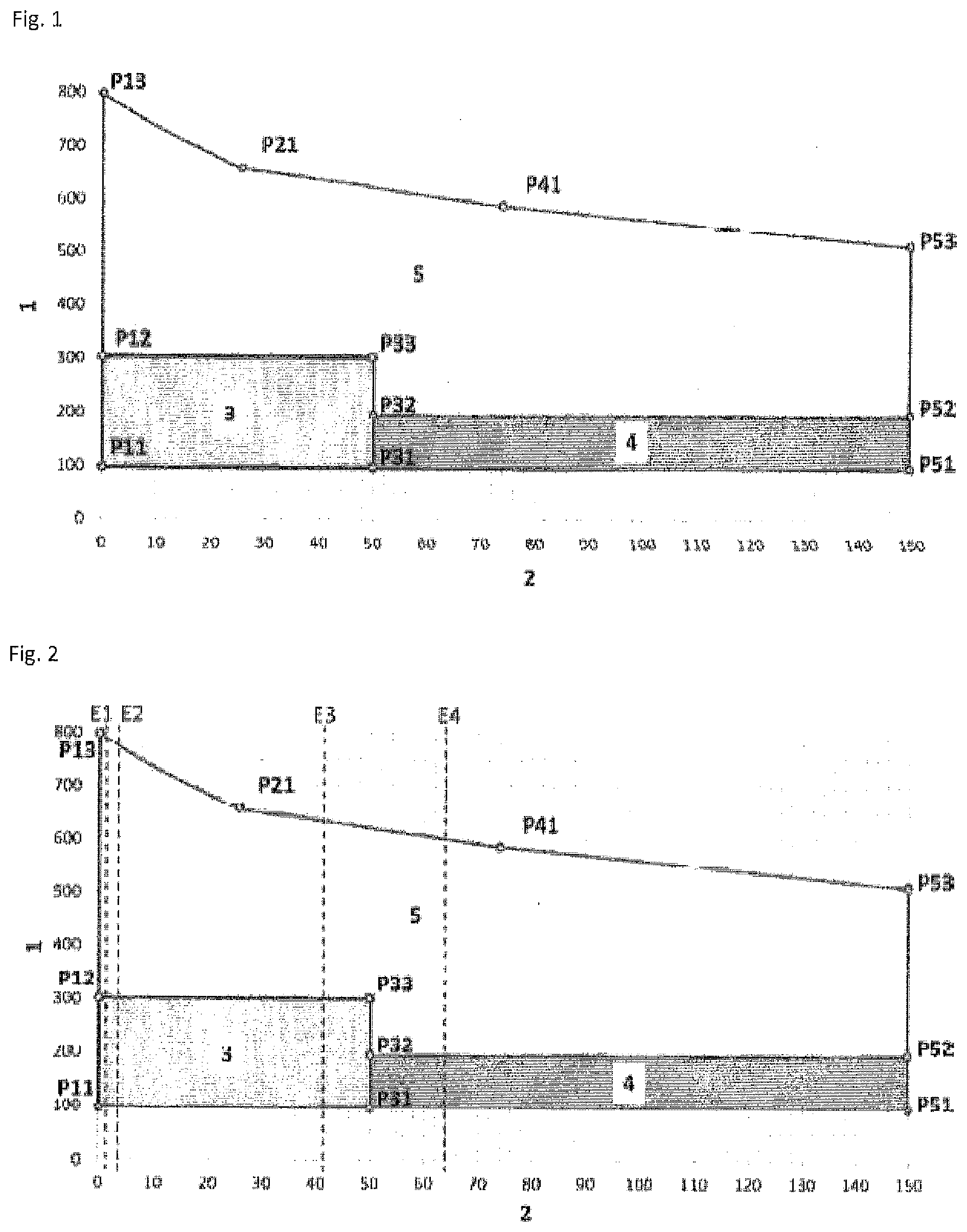
[0052] Step (B) of the method according to the invention comprises determining a WOP value on the basis of the rolling degree to sheet thickness ratio WGB within a surface spanned by straight connecting paths between the points P11 (WGB 0.8, WOP 100) and P13 (WGB 0.8, WOP 800), P13 (WGB 0.8, WOP 800) and P21 (WGB 26, WOP 650), P21 (WGB 26, WOP 650) and P41 (WGB 74, WOP 590), P41 (WGB 74, WOP 590) and P53 (WGB 150, WOP 520), P53 (WGB 150, WOP 520) and P51 (WGB 150, WOP 100) and P51 (WGB 150, WOP 100) and P11 (WGB 0.8, WOP 100) in a coordinate system in which the WOP value is plotted on the y axis and the rolling degree to sheet thickness ratio is plotted on the x axis, as preferably shown in FIG. 1. According to the invention, a suitable WOP value range is thus determined, from which a WOP value can in turn be selected. According to the invention, however, all the WOP values lying in the specific WOP value range fulfill the condition that a steel component having a content of diffusible hydrogen of at most 0.4 ppm is obtained.
[0053] Step (B) of the method according to the invention serves to determine a WOP value on the basis of the rolling degree to sheet thickness ratio of the flat steel product used, with WOP meaning "hydrogen-related furnace parameter" and not having a unit. The WOP value then provides information about the process parameters with which the heat treatment in step (C) should take place so that steel components having a content of diffusible hydrogen of at most 0.4 ppm are obtained.
[0054] When determining the WOP value according to the present invention, a range for suitable WOP values is determined using the rolling degree to sheet thickness ratio. From this range, it is then preferably possible to select a WOP value which is then used to determine the corresponding value for T.sub.furnace, t.sub.furnace and T.sub.dew point using the equation of general formula (I). In general, however, all values present in the accordingly determined range of WOP values are suitable for being substituted into the equation of general formula (I) to determine corresponding values for T.sub.furnace, t.sub.furnace and T.sub.dew point.
[0055] Step (B) of the method according to the invention is preferably carried out in that the WOP value is determined graphically at a predetermined rolling degree to sheet thickness ratio (region A) within a surface spanned by straight connecting paths between the points P11 (WGB 0.8, WOP 100) and P13 (WGB 0.8, WOP 800), P13 (WGB 0.8, WOP 800) and P21 (WGB 26, WOP 650), P21 (WGB 26, WOP 650) and P41 (WGB 74, WOP 590), P41 (WGB 74, WOP 590) and P53 (WGB 150, WOP 520), P53 (WGB 150, WOP 520) and P51 (WGB 150, WOP 100) and P51 (WGB 150, WOP 100) and P11 (WGB 0.8, WOP 100) in a coordinate system in which the WOP value is plotted on the y axis and the rolling degree to sheet thickness ratio is plotted on the x axis. The corresponding graph is shown in FIG. 1; region A results from a combination of the illustrated partial surfaces "3", "4" and "5" In FIG. 1.
[0056] In a preferred embodiment of the method according to the invention, the WOP value is determined according to step (B) of the method according to the invention within a surface spanned by straight connecting lines between the points P12 (WGB 0.8, WOP 300) and P13 (WGB 0.8, WOP 800), P13 (WGB 0.8, WOP 800) and P21 (WGB 26, WOP 650), P21 (WGB 26, WOP 650) and P41 (WGB 74, WOP 590), P41 (WGB 74, WOP 590) and P53 (WGB 150, WOP 520), P53 (WGB 150, WOP 520) and P52 (WGB 150, WOP 200), P52 (WGB 150, WOP 200) and P32 (WGB 50, WOP 200), P32 (WGB 50, WOP 200) and P33 (WGB 50, WOP 300) and P33 (WGB 50, WOP 300) and P12 (WGB 0.8, WOP 300) in a coordinate system in which the WOP value is plotted on the y axis and the rolling degree to sheet thickness ratio (WGB) is plotted on the x axis (region B). The corresponding graph is shown in FIG. 1; region B is the illustrated partial surfaces "5" without the partial surfaces "3" and "4" in FIG. 1.
[0057] By using the WOP value determined in step (B) of the method according to the invention, it can then be determined according to the invention at which dew point temperature of the furnace atmosphere T.sub.dew point at which average furnace temperature T.sub.furnace and for which duration t.sub.furnace step (C) of the method according to the invention is carried out.
[0058] Step (C) of the method according to the invention comprises treating the flat steel product at an average furnace temperature T.sub.furnace (in K) for a duration t.sub.furnace (In h), wherein the dew point temperature of the furnace atmosphere T.sub.dew point (in K), the average furnace temperature T.sub.furnace (in K) and the duration t.sub.furnace (in h) are set according to the following equation of general formula (1)
WOP = T furnace K log ( t furnace h + 1.15 ) + ( T dew point K - 2 4 3 . 1 5 ) 1.6 , ( 1 ) ##EQU00004##
such that the WOP value is within the interval specified by means of FIG. 1 between the minimum and maximum WOP values.
[0059] The furnace temperature T.sub.furnace (in K) is the temperature which, on average, prevails in the furnace in step (C) of the method according to the invention. According to the invention, T.sub.furnace may assume any value which a person skilled in the art considers suitable. In the method according to the invention, T.sub.furnace is preferably AC1 to 1373 K, preferably 1113 to 1253 K, particularly preferably 1133 to 1223 K, more particularly preferably 1153 to 1193 K. Here, AC1 means the first austenitizing temperature, which is dependent on the alloy composition.
[0060] The duration t.sub.furnace (in h) is the time over which said furnace temperature T.sub.furnace prevails in step (C). According to the invention, t.sub.furnace may assume any value which a person skilled in the art considers suitable. In the method according to the invention, t.sub.furnace in particular describes the period in which the flat steel product is moved through a continuous furnace or remains in a stationary furnace. In the method according to the invention, t.sub.furnace is preferably from 0.05 to 0.5 h, preferably from 0.067 to 0.25 h, particularly preferably from 0.067 to 0.4 h.
[0061] In one embodiment, furnace temperature T.sub.furnace duration t.sub.furnace, and WOP value are used to calculate and then set the dew point temperature of the furnace atmosphere of the furnace T.sub.dew point by means of equation (1). The dew point temperature of the furnace T.sub.dew point (in K) is, for example, 243.15 to 333.15 K, preferably 253.15 to 303.15 K, particularly preferably 263.15 to 293.15 K.
[0062] In a further preferred embodiment, the dew point temperature of the furnace atmosphere of the furnace T.sub.dew point, duration t.sub.furnace and WOP value are used to calculate and then set the furnace temperature T.sub.furnace by means of equation (1).
[0063] In a further preferred embodiment, the dew point temperature of the furnace atmosphere of the furnace T.sub.dew point, furnace temperature T.sub.furnace and WOP value are used to calculate and then set the duration t.sub.furnace by means of equation (1).
[0064] Step (C) of the method according to the invention can generally be carried out in any furnace known to a person skilled in the art, for example roller hearth furnaces, chamber furnaces, multilayer chamber furnaces, or walking beam furnaces.
[0065] Step (D) of the method according to the invention comprises forming the heated flat steel product from step (C) in a mold while simultaneously cooling to obtain the steel component.
[0066] In general, in step (D) of the method according to the invention, all methods known to a person skilled in the art can be used for hot forming, for example as described in Warmumformung im Automobilbau-Verfahren, Werkstoffe, Oberflachen [Hot Forming in the Automotive Industry--Processes, Materials, Surfaces], Landsberg/Lech: Verl. Moderne Industrie, 2012, Die Bibliothek der Technik [The Ubrary of Technology].
[0067] In step (D) of the method according to the invention, the desired steel component is obtained from the flat steel product from step (C) by forming. For the desired tempered microstructure, for example at least 80% martensite, with the remainder being bainite, ferrite and retained austenite, to be formed in the steel component, the forming takes place with simultaneous cooling. The cooling in step (C) of the method according to the invention is preferably carried out at a rate of from 27 to 1000 K/s, particularly preferably from 50 to 500 K/s. The present invention therefore preferably relates to the method according to the invention, wherein the cooling in step (D) takes place at a cooling rate of from 27 to 500 K/s.
[0068] The present invention also relates to a steel component containing (all data in wt. %)
[0069] 0.06 to 0.50, preferably 0.18 to 0.37, particularly preferably 0.20 to 0.25 C,
[0070] 0.50 to 3.0, preferably 0.80 to 2.00, particularly preferably 1.00 to 1.60 Mn,
[0071] 0.10 to 0.50, preferably 0.15 to 0.40, particularly preferably 0.20 to 0.30 Si,
[0072] 0.01 to 1.00, preferably 0.10 to 0.5, particularly preferably 0.10 to 0.40 Cr,
[0073] up to 0.20, preferably 0.01 to 0.10, particularly preferably 0.01 to 0.05 Ti,
[0074] up to 0.10, preferably 0.01 to 0.05, particularly preferably 0.02 to 0.05 Al,
[0075] up to 0.10, preferably 0.00 to 0.05, particularly preferably 0.00 to 0.02 P,
[0076] up to 0.1, preferably 0.001 to 0.1 Nb,
[0077] up to 0.01 N,
[0078] up to 0.05, preferably 0.00 to 0.005, particularly preferably 0.00 to 0.003 S and
[0079] up to 0.1, preferably 0.001 to 0.05, particularly preferably 0.002 to 0.0035 B,
[0080] remainder Fe and unavoidable impurities,
[0081] comprising a coating containing (all data in wt. %)
[0082] 3 to 15 Si,
[0083] 1 to 3.5 Fe,
[0084] 0.05 to 5.0, preferably 0.05 to 1.5, particularly preferably 0.11 to 0.6 alkali and/or alkaline earth metals, remainder Al and unavoidable impurities,
[0085] produced using the method according to the invention. Preferably, the coating weight of the double-sided coating of the steel component according to the invention is from 20 to 240 g/m.sup.2.
[0086] The steel component according to the invention preferably has a fully alloyed alloy layer between the steel substrate and the Al-based coating. The steel component according to the invention preferably has a fully alloyed alloy layer in a thickness of from 5 to 60 .mu.m, preferably 10 to 45 .mu.m. The thickness of the alloy layer can be measured by methods known to a person skilled in the art (e.g. according to DIN EN ISO 1463).
[0087] The details and preferred embodiments mentioned with regard to the method according to the invention apply accordingly to the steel component according to the invention.
[0088] The present invention also relates to the use of a coated steel component according to the invention in the automotive sector, in particular as a bumper support/reinforcement, door reinforcement, B-pillar reinforcement, A-pillar reinforcement, roof frame or body sill.
[0089] With regard to the individual features of the use according to the invention and of the preferred embodiments, that said with regard to the method according to the invention applies accordingly.
DRAWINGS
[0090] FIG. 1 shows a graph in which the WOP value is plotted against the rolling degree to sheet thickness ratio.
[0091] On said graph, the numbering means the following:
[0092] 1 WOP value (hydrogen-related furnace parameter value)
[0093] 2 WGB (rolling degree to sheet thickness ratio)
[0094] 3 Partial surface "3"
[0095] 4 Partial surface "4"
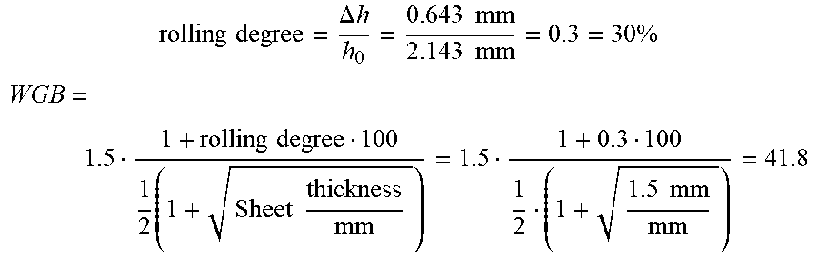
[0096] Partial surface "5" FIG. 2 shows, by way of example, how the WOP value is determined with a known rolling degree to sheet thickness ratio according to the invention, and in this case the numbering means the following:
[0097] E1 rolling degree 0.5%, starting sheet thickness 3.0 mm, rolling degree to sheet thickness ratio 1.6, resulting in WOP value of from 300 to 790.
[0098] E2 rolling degree 2.5%, starting sheet thickness 3.0 mm, rolling degree to sheet thickness ratio 3.8, resulting in WOP value of from 300 to 780.
[0099] E3 rolling degree 30%, starting sheet thickness 1.5 mm, rolling degree to sheet thickness ratio 41.8, resulting in WOP value of from 300 to 630.
[0100] E4 rolling degree 50%, starting sheet thickness 1.98 mm, rolling degree to sheet thickness ratio 63.6, or rolling degree 47%, starting sheet thickness 1.5 mm, rolling degree to sheet thickness ratio 64.7, resulting in WOP value of from 200 to 600 in each case.
EXAMPLES
Example 1
[0101] The following embodiments serve to explain the invention in greater detail.
[0102] Blanks are used which have been obtained from melts having the alloy components according to Table 1.
TABLE-US-00001 TABLE 1 Melt composition of the flat steel products used Alloy Alloy component in wt. % elements Melt A Melt B Melt C Melt D C 0.224 0.212 0.219 0.212 to 0.225 Si 0.23 0.22 0.26 0.21 to 0.27 Mn 1.20 1.11 1.14 1.11 to 1.20 P 0.014 0.009 0.013 0.009 to 0.016 S 0.0029 0.0013 0.0023 0.0006 to 0.0029 Al total 0.035 0.027 0.032 0.026 to 0.038 Cr 0.190 0.187 0.183 0.180 to 0.190 Nb 0.001 0.001 0.001 0.001 to 0.001 Mo 0.0055 0.0018 0.0040 0.0016 to 0.0055 Ti 0.028 0.029 0.025 0.020 to 0.033 B 0.0022 0.0024 0.0026 0.0021 to 0.0028 All data in wt. %, remainder Fe and unavoidable impurities
[0103] The flat steel products used have a coating containing 9 to 10 wt. % Si, 2 to 3.5 wt. % Iron, remainder aluminum and the amount of Mg set out in Table 2. The coating weight, the sheet thickness and the rolling degree of the flat steel products used are likewise set out in Table 2. The corresponding WOP value is then determined in the graph according to FIG. 1 by means of the rolling degree to sheet thickness ratio (formula 3), and T.sub.furnace, t.sub.furnace, and T.sub.dew point of the furnace atmosphere are subsequently determined and set by means of formula (1). The thus heated flat steel product is then removed from the furnace and inserted into a mold after a transport time of 6 seconds. After insertion into the mold, this mold immediately closes and remains in the closed state for approx. 20 seconds, in order to thereby cool the component to <80.degree. C. by contact with the cooled molds. Samples are taken from the manufactured steel components, which are analyzed with regard to the amount of diffusible hydrogen contained (H.sub.diff) by means of desorption mass spectrometry using heated samples (thermal desorptlon mass spectrometry (TDMS)).
TABLE-US-00002 TABLE 2 Mg Coating weight Sheet Rolling Serial content on both sides thickness degree T.sub.furnace t.sub.furnace T.sub.dew point H.sub.diff WOP no. Melt [wt. %] [g/m.sup.2] [mm] [%] WGB [K] [h] [K] [ppm] value Region V1 A 0.3 80 1.50 0 1.3 1193.15 0.100 288.15 0.12 557 -- V2 A 0.3 80 1.50 0 1.3 1193.15 0.167 288.15 0.17 584 -- V3 A 0.3 140 1.50 0 1.3 1193.15 0.222 288.15 0.13 606 -- V4 A 0.3 140 1.50 0 1.3 1193.15 0.100 288.15 0.14 557 -- V5 A 0 140 1.50 0 1.3 1193.15 0.222 288.15 0.45 606 -- 6 A 0.3 140 1.10 27 41.0 1193.15 0.100 248.15 0.07 129 A 7 A 0.3 140 1.10 27 41.0 1193.15 0.167 248.15 0.05 156 A 8 A 0.3 140 1.10 27 41.0 1193.15 0.222 248.15 0.05 177 A 9 A 0.3 140 1.10 27 41.0 1193.15 0.100 268.15 0.26 288 A 10 A 0.3 140 1.10 27 41.0 1193.15 0.167 268.15 0.14 315 B 11 A 0.3 140 1.10 27 41.0 1193.15 0.222 268.15 0.12 336 B 12 A 0.3 140 0.80 47 76.0 1193.15 0.100 248.15 0.15 129 A 13 A 0.3 140 0.80 47 76.0 1193.15 0.167 248.15 0.13 156 A 14 A 0.3 140 0.80 47 76.0 1193.15 0.222 248.15 0.05 177 A 15 A 0.3 140 0.80 47 76.0 1193.15 0.100 268.15 0.34 288 A 16 A 0.3 140 0.80 47 76.0 1193.15 0.167 268.15 0.29 315 B 17 A 0.3 140 0.80 47 76.0 1193.15 0.222 268.15 0.22 336 B V18 A 0.3 140 0.80 47 76.0 1193.15 0.222 288.15 0.89 606 -- V19 C 0 140 1.50 0 1.3 1193.15 0.083 288.15 0.47 550 -- V20 C 0 140 1.50 0 1.3 1193.15 0.167 288.15 0.59 584 -- V21 C 0 140 1.50 0 1.3 1193.15 0.083 268.15 0.20 281 -- V22 C 0 140 1.50 0 1.3 1193.15 0.083 248.15 0.10 122 -- 23 B 0.4 140 1.35 30 43.0 1193.15 0.083 268.15 0.20 281 A 24 B 0.4 140 1.35 30 43.0 1193.15 0.167 268.15 0.17 315 B 25 B 0.4 140 1.35 30 43.0 1193.15 0.083 288.15 0.22 550 B 26 B 0.4 140 1.35 30 43.0 1193.15 0.167 288.15 0.31 584 B 27 B 0.4 140 1.00 50 76.5 1193.15 0.083 268.15 0.11 281 A 28 B 0.4 140 1.00 50 76.5 1193.15 0.083 268.15 0.13 281 A 29 B 0.4 140 1.00 50 76.5 1193.15 0.167 268.15 0.11 315 B 30 B 0.4 140 1.00 50 76.5 1193.15 0.167 268.15 0.12 315 B 31 B 0.4 140 1.00 50 76.5 1193.15 0.083 288.15 0.26 550 B 32 B 0.4 140 1.00 50 76.5 1193.15 0.167 288.15 0.28 584 B V33 D 0.3 140 1.50 0 1.3 1253.15 0.083 288.15 0.27 554 -- V34 D 0.3 140 1.50 0 1.3 1153.15 0.167 288.15 0.27 579 -- V35 D 0 140 1.50 0 1.3 1153.15 0.250 288.15 0.47 610 -- 36 D 0 140 1.50 25 35.1 1193.15 0.083 268.15 0.29 281 -- V37 D 0 140 1.50 25 35.1 1193.15 0.050 288.15 0.52 536 -- 38 D 0 140 1.50 25 35.1 1193.15 0.083 258.15 0.05 185 A 39 D 0 140 1.50 25 35.1 1193.15 0.167 258.15 0.22 219 A 40 D 0.5 140 1.00 0 1.5 1193.15 0.167 288.15 0.27 584 B 41 D 0.5 140 1.97 0 1.2 1193.15 0.083 288.15 0.10 550 B 42 D 0.5 140 1.97 0 1.2 1193.15 0.250 288.15 0.30 616 B V43 D 0 140 1.50 25 35.1 1193.15 0.083 288.15 0.85 550 -- V44 D 0 140 1.50 25 35.1 1193.15 0.167 268.15 0.49 315 -- 45 D 0.3 140 1.50 0 1.3 1193.15 0.083 298.15 0.24 718 B 46 D 0 140 1.30 30 43.5 1193.15 0.083 268.15 0.27 281 A 47 D 0 140 1.30 30 43.5 1193.15 0.083 268.15 0.27 281 A V48 D 0 140 1.30 30 43.5 1193.15 0.083 288.15 0.57 550 -- V49 D 0 140 0.95 50 77.5 1193.15 0.083 268.15 0.58 281 -- V50 D 0 140 0.95 50 77.5 1193.15 0.167 268.15 0.47 315 -- V Comparative example
Example 2
[0104] Determination by way of example of allowable values for T.sub.furnace, t.sub.furnace and T.sub.dew point to maintain an H.sub.diff value of 0.4 ppm in produced components made of flat steel products.
Example E3 from FIG. 2:
[0105] h.sub.0=2.143 mm; h.sub.1=sheet thickness=1.5 mm; .DELTA.h=0.643 mm; coating with Mg 0.35 wt. %
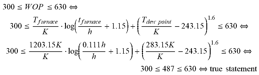
rolling degree = .DELTA. h h 0 = 0.643 mm 2.143 mm = 0.3 = 30 % ##EQU00005## WGB = 1.5 1 + rolling degree 100 1 2 ( 1 + Sheet thickness mm ) = 1.5 1 + 0.3 100 1 2 ( 1 + 1.5 mm mm ) = 41.8 ##EQU00005.2##
[0106] For the WGB value of 41.8, a WOP value of from 300 to 630 can be read out from FIG. 1 or calculated using the specified points. Now the three parameters T.sub.furnace, t.sub.furnace and T.sub.dew point can be set to result in a WOP value of 300.ltoreq.WOP.ltoreq.630, for example: T.sub.furnace=930.degree. C.=1203.15 K; t.sub.furnace=400 s=0.111 h; and T.sub.dew point=10.degree. C.=283.15 K
3 0 0 .ltoreq. W O P .ltoreq. 630 .revreaction. 300 .ltoreq. T f u r n a c e K log ( t f u r n a c e h + 1 . 1 5 ) + ( T dew point K - 2 4 3 . 1 5 ) 1 . 6 .ltoreq. 630 .revreaction. 300 .ltoreq. 1 203.15 K K log ( 0.111 h h + 1 . 1 5 ) + ( 2 8 3 . 1 5 K K - 2 4 3 . 1 5 ) 1 . 6 .ltoreq. 630 .revreaction. 300 .ltoreq. 487 .ltoreq. 630 .revreaction. true statement ##EQU00006##
[0107] Since the calculated WOP value of 487 is between 300 and 630, the selected parameters allow a maximum H.sub.diff value of 0.4 ppm to be maintained in the component.
INDUSTRIAL APPLICABILITY
[0108] The steel component produced according to the invention has a low tendency toward hydrogen-induced fractures under load stresses and can therefore advantageously be used in the automotive sector, aircraft construction or rail vehicle construction.
* * * * *
uspto.report is an independent third-party trademark research tool that is not affiliated, endorsed, or sponsored by the United States Patent and Trademark Office (USPTO) or any other governmental organization. The information provided by uspto.report is based on publicly available data at the time of writing and is intended for informational purposes only.
While we strive to provide accurate and up-to-date information, we do not guarantee the accuracy, completeness, reliability, or suitability of the information displayed on this site. The use of this site is at your own risk. Any reliance you place on such information is therefore strictly at your own risk.
All official trademark data, including owner information, should be verified by visiting the official USPTO website at www.uspto.gov. This site is not intended to replace professional legal advice and should not be used as a substitute for consulting with a legal professional who is knowledgeable about trademark law.