Method For Heat-treating Uppermost Surface Of Spheroidal Graphite Cast Iron And Spheroidal Graphite Cast Iron Heat-treated By Th
Kwon; Eun-Soo ; et al.
U.S. patent application number 16/662633 was filed with the patent office on 2020-07-09 for method for heat-treating uppermost surface of spheroidal graphite cast iron and spheroidal graphite cast iron heat-treated by th. The applicant listed for this patent is Hyundai Motor Company Kia Motors Corporation. Invention is credited to Eun-Soo Kwon, Hyung-Gook Lee, Yong-Bo Sim.
| Application Number | 20200216923 16/662633 |
| Document ID | / |
| Family ID | 71404956 |
| Filed Date | 2020-07-09 |

| United States Patent Application | 20200216923 |
| Kind Code | A1 |
| Kwon; Eun-Soo ; et al. | July 9, 2020 |
METHOD FOR HEAT-TREATING UPPERMOST SURFACE OF SPHEROIDAL GRAPHITE CAST IRON AND SPHEROIDAL GRAPHITE CAST IRON HEAT-TREATED BY THE SAME
Abstract
Disclosed are a method for heat-treating a surface of a spheroidal graphite cast iron, particularly, heat-treating an uppermost surface of spheroidal graphite cast iron, and spheroidal graphite cast iron heat-treated by the same. The method may include first heat treating for forming ferrite and second heat treating for oxy-nitriding. The spheroidal graphite cast iron heat-treated includes an oxidation layer and a compound layer having a thickness of about 15 to 30 .mu.m, which may be uniform. The method of the heat-treating may decrease the pearlite fraction in the uppermost surface of spheroidal graphite cast iron and increase the ferrite fraction by forming ferrite, thereby forming a compound layer having a thickness of about 15 to 30 .mu.m during an oxy-nitriding heat treatment.
| Inventors: | Kwon; Eun-Soo; (Daegu, KR) ; Lee; Hyung-Gook; (Iksan, KR) ; Sim; Yong-Bo; (Seoul, KR) | ||||||||||
| Applicant: |
|
||||||||||
|---|---|---|---|---|---|---|---|---|---|---|---|
| Family ID: | 71404956 | ||||||||||
| Appl. No.: | 16/662633 | ||||||||||
| Filed: | October 24, 2019 |
| Current U.S. Class: | 1/1 |
| Current CPC Class: | C23C 8/02 20130101; C21D 5/00 20130101; C23C 8/28 20130101; C23C 8/30 20130101; C23C 8/10 20130101; C23C 8/80 20130101 |
| International Class: | C21D 5/00 20060101 C21D005/00; C23C 8/02 20060101 C23C008/02; C23C 8/10 20060101 C23C008/10; C23C 8/28 20060101 C23C008/28; C23C 8/80 20060101 C23C008/80 |
Foreign Application Data
| Date | Code | Application Number |
|---|---|---|
| Jan 7, 2019 | KR | 10-2019-0001485 |
Claims
1. A method for heat-treating a surface of spheroidal graphite cast iron, comprising: first heat treating the spheroidal graphite cast iron for forming ferrite; and second heat treating for oxy-nitriding the spheroidal graphite cast iron.
2. The method of claim 1, wherein the first heat treating comprises: heating the spheroidal graphite cast iron to a first heating temperature of about 940 to 1,060.degree. C.; and maintaining the first heating temperature, wherein a total time for the first heat treating time is about 80 to 100 minutes.
3. The method of claim 2, wherein the first heat treatment step further comprises: air-cooling the spheroidal graphite cast iron for about 110 to 130 minutes.
4. The method of claim 1, wherein the second heat treating comprises: nitrocarburizing by introducing a gas; oxidizing the spheroidal graphite cast iron; and cooling; wherein the nitrocarburizing is performed at a second heat treating temperature of about 550.degree. C. to 570.degree. C. for about 720 minutes to 1,200 minutes.
5. The method of claim 4, wherein the cooling is furnace cooling.
6. A spheroidal graphite cast iron comprising: an oxidation layer; and a compound layer, wherein the compound layer has a thickness of about 15 to 30 .mu.m.
7. The spheroidal graphite cast iron of claim 6, wherein the thickness of the compound layer is uniform.
8. The spheroidal graphite cast iron of claim 6, wherein an uppermost surface of the spheroidal graphite cast iron comprises ferrite fraction in about 60 to 80%.
9. The spheroidal graphite cast iron of claim 8, wherein the compound layer comprises: a pore layer; and a nitride compound layer comprising a gamma prime phase and an epsilon phase.
10. The spheroidal graphite cast iron of claim 9, wherein the nitride compound layer consists of the gamma prime phase and the epsilon phase.
11. The spheroidal graphite cast iron of claim 9, wherein the nitride compound layer comprises the epsilon phase in about 80% or greater.
12. The spheroidal graphite cast iron of claim 9, wherein the compound layer has the hardness of about HV 600 to 1000.
13. The spheroidal graphite cast iron of claim 9, wherein the compound layer comprises the pore layer in a fraction of about 25 to 35%.
14. The spheroidal graphite cast iron of claim 10, wherein the compound layer comprises the pore layer in a fraction of about 25 to 35%.
15. The spheroidal graphite cast iron of claim 9, wherein the compound layer comprises the oxidation layer, the pore layer, the gamma prime phase and the epsilon phase from the uppermost surface of the spheroidal graphite cast iron.
16. The spheroidal graphite cast iron of claim 6, the cast iron comprises the oxidation layer and the compound layer from an uppermost surface of the cast iron.
17. A vehicle part comprising a spheroidal graphite case iron of claim 6.
18. A vehicle comprising a vehicle part of claim 17.
Description
CROSS-REFERENCE TO RELATED APPLICATIONS
[0001] This application claims priority under 35 U.S.C. .sctn. 119 to Korean Patent Application No. 10-2019-0001485, filed on Jan. 7, 2019, in the Korean Intellectual Property Office, the disclosure of which is incorporated herein by reference in its entirety.
FIELD OF THE INVENTION
[0002] The present invention relates to a method for heat-treating a surface of a spheroidal graphite cast iron, for example, heat-treating an uppermost surface of the spheroidal graphite cast iron and spheroidal graphite cast iron heat-treated by the same. Particularly, the method may include an oxy-nitriding heat treatment (second heat treating) of the uppermost surface of spheroidal cast iron.
BACKGROUND OF THE INVENTION
[0003] Steel materials used as various parts of an automobile have been subjected to various surface treatments such as high frequency, oxy-nitration, and phosphate coating in order to secure abrasion resistance and strength.
[0004] For instance, the oxy-nitriding heat treatment is a heat treatment of increasing abrasion resistance and corrosion resistance by introducing nitrogen [N] into a material in a high temperature atmosphere to produce nitrides, and then spraying water vapor to form an oxidation layer on the uppermost surface of a compound layer.
[0005] The oxy-nitriding heat treatment has been frequently performed on general carbon steel as a heat treatment for securing durability and abrasion resistance, but the oxy-nitriding heat treatment has not been applied well to spheroidal graphite cast iron even though the oxy-nitriding heat treatment also needs to be applied in order to secure abrasion resistance, and the like. This is because spheroidal graphite cast iron not only includes a greater amount of silicon (Si) than a conventional carbon steel, but also has a pearlite fraction of 60% or greater. In particular, even though the pearlite fraction is for having high toughness and tensile strength, when an oxy-nitriding heat treatment is performed on spheroidal graphite cast iron, a compound layer is disadvantageously formed due to pearlite on the surface of spheroidal graphite cast iron, so that the surface treatment effect cannot be exhibited because the thickness of the compound layer is formed at a level of 1/2 to 1/3 as compared to the conventional carbon steel.
SUMMARY OF THE INVENTION
[0006] In preferred aspects, provided is a method of forming a compound layer having a predetermined thickness or greater by performing an oxy-nitriding heat treatment while reducing the pearlite fraction on the uppermost surface of spheroidal graphite cast iron.
[0007] The term "spheroidal graphite cast iron" as used herein refers to a cast iron or a cast ferrous alloy including graphite (e.g., nodular graphite, spheroid-like or spheroidal graphite) as one of the carbon source. The term "spheroidal graphite cast iron" may be used interchangeably with ductile cast iron so as to have same grades and mechanical and chemical properties as ductile iron. For instance, the spheroidal graphite cast iron may suitably include carbon in an amount of about 3.2 to 3.60 wt % of the total weight of the composition as well as other components such as silicon, manganese, magnesium, phosphorus, sulfur, and/or copper with remaining balance of iron.
[0008] The term "uppermost surface" as used herein refers to a surface area and underneath thereof, which may include a space/area from the surface to a predetermined depth, preferably a depth of up about 50, 100 or 200 .mu.m from the exposed surface, more typically a depth up to about 100 .mu.m from the exposed surface.
[0009] In an aspect, provided is a method for heat-treating a surface of a spheroidal graphite cast iron, particularly an uppermost surface of the spheroidal graphite cast iron. The method may include first heat treating the spheroidal graphite cast iron for forming ferrite, and second heat treating for oxy-nitriding the spheroidal graphite cast iron.
[0010] As referred to herein, the term "spheroidal graphite cast iron" is a type of iron that is also known as ductile iron or ductile cast iron and may have graphite within that may appear like spheres or nodules under high magnification (e.g. 100.times. or magnification).
[0011] The term "oxy-nitriding" as used herein refers to a process for nitriding and oxidation (oxidizing), which may be combined or in separate sequential process. Preferably, the oxy-nitriding may include sequential processes of respective nitriding and oxidizing.
[0012] The term "nitriding" or "nitrocarburizing" as used herein refers to a process for diffusing nitrogen on a surface of a metal (e.g. metal alloy, steel or cast iron) by heat treating using gas, salt or nitrogen media in plasma. Preferably, the nitriding process may be performed by using nitrogen rich gas (e.g., NH.sub.3) so as to form a nitride layer at high temperature, e.g., at a temperature greater than about 500.degree. C., 600.degree. C., 700.degree. C., 800.degree. C., 900.degree. C., or 1000.degree. C., or by applying heat.
[0013] The term "oxidation" or "oxidizing" as used herein refers to a process of inducing a reaction in which a metal and oxygen combined to form an oxide, or oxidation layer or deposit thereof. Exemplary oxidation process may include heat treating or high temperature oxidation, e.g., at a temperature greater than about 500.degree. C., 600.degree. C., 700.degree. C., 800.degree. C., 900.degree. C., or 1000.degree. C.
[0014] Preferably, the first heat treating for forming ferrite may include heating the spheroidal graphite cast iron to a first heating temperature of about 940 to 1,060.degree. C. and maintaining the first heating temperature, and a total time for the first heat treating may be about 80 to 100 minutes.
[0015] Preferably, the first heat treating for forming ferrite may further include air-cooling the spheroidal graphite cast iron for about 110 to 130 minutes.
[0016] Preferably, the second heat treating for oxy-nitriding may include nitrocarburizing by introducing a gas, oxidizing the spheroidal graphite cast iron, and cooling. The nitrocarburizing may be performed at a second heat treating temperature of about 550.degree. C. to 570.degree. C. for about 720 minutes to 1,200 minutes.
[0017] In another aspect, provided is a spheroidal graphite cast iron heat-treated by the heat treatment. In particular, an uppermost surface of spheroidal graphite cast iron may be treated by the method described herein. The spheroidal graphite cast iron may include an oxidation layer and a compound layer, in which a thickness of the compound layer is 15 to 30 .mu.m. Preferably, the thickness of the compound layer may be uniform.
[0018] Preferably, an uppermost surface of the spheroidal graphite cast iron may include a ferrite fraction in about 60 to 80%.
[0019] Preferably, the compound layer may include a pore layer and a nitride compound layer. The nitride compound layer may include a gamma prime phase and an epsilon phase. Alternatively, the nitride compound layer may consist of the gamma prime phase and the epsilon phase.
[0020] Preferably, the compound layer may include the pore layer fraction in about 25 to 35%.
[0021] Preferably, the nitride compound layer may include the epsilon phase in about 80% or greater.
[0022] Preferably, the compound layer may have a hardness of about HV 600 to 1000.
[0023] According to various exemplary embodiments, the compound layer having a thickness of 15 to 30 .mu.m, which may be formed during oxy-nitriding heat treating (e.g., second heat treating) by increasing the ferrite fraction, may be formed on the uppermost surface of spheroidal graphite cast iron.
[0024] According to various exemplary embodiments, abrasion resistance of the spheroidal graphite cast iron may be by controlling the pore layer fraction to about 25 to 35%.
[0025] Preferably, the compound layer may include the oxidation layer, the pore layer, the gamma prime phase and the epsilon phase from the uppermost surface of the spheroidal graphite cast iron.
[0026] The spheroidal graphite cast iron may include the oxidation layer and the compound layer from an uppermost surface of the cast iron.
[0027] Further provided is a vehicle part that may include the spheroidal graphite cast iron as described herein.
[0028] Also provided is a vehicle that may include the vehicle part as described herein.
[0029] Other aspects of the invention are provided infra.
BRIEF DESCRIPTION OF THE DRAWINGS
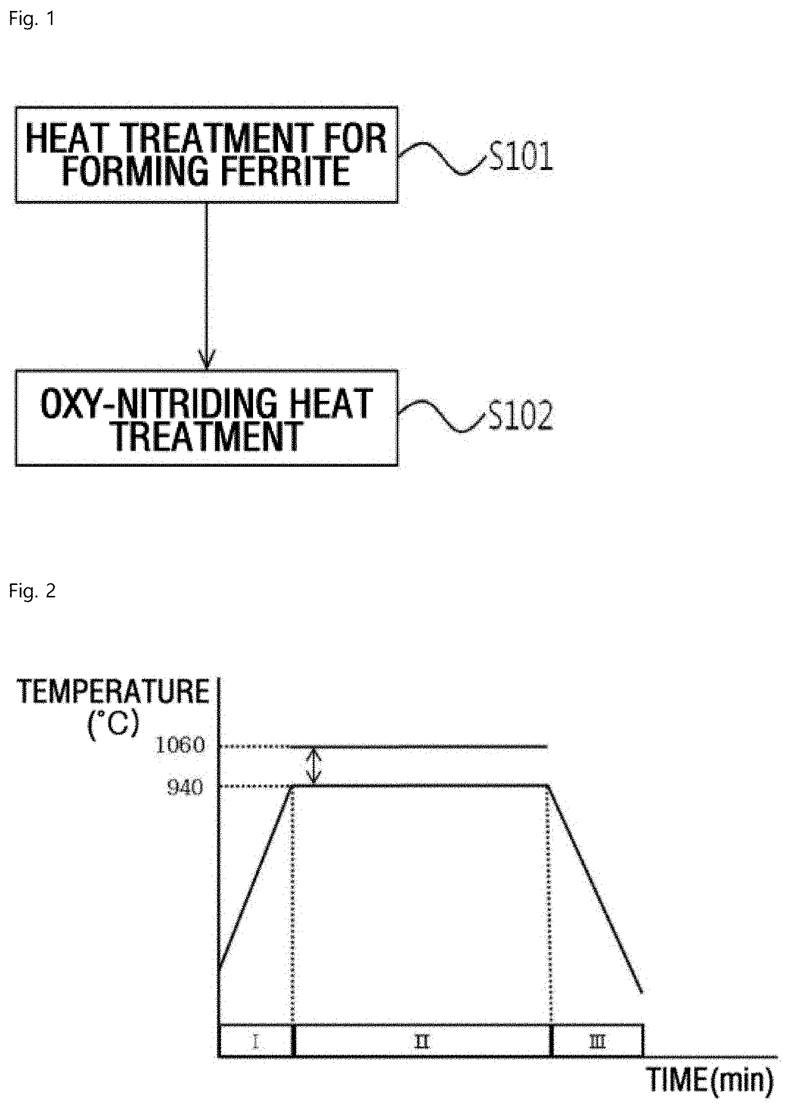
[0030] FIG. 1 shows an exemplary method for heat-treating an exemplary cast iron including spheroidal graphite cast iron on its uppermost surface according to an exemplary embodiment of the present invention.
[0031] FIG. 2 shows an exemplary heat treatment step for forming ferrite according to an exemplary embodiment of the present invention.
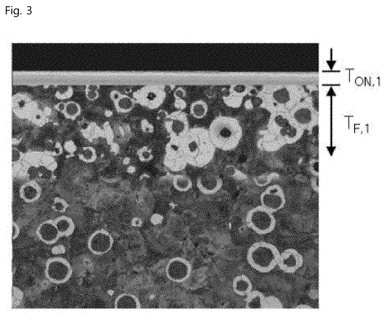
[0032] FIG. 3 shows an images of an exemplary microstructure of spheroidal graphite cast iron after the heat treatment step for forming ferrite according to an exemplary embodiment of the present invention.
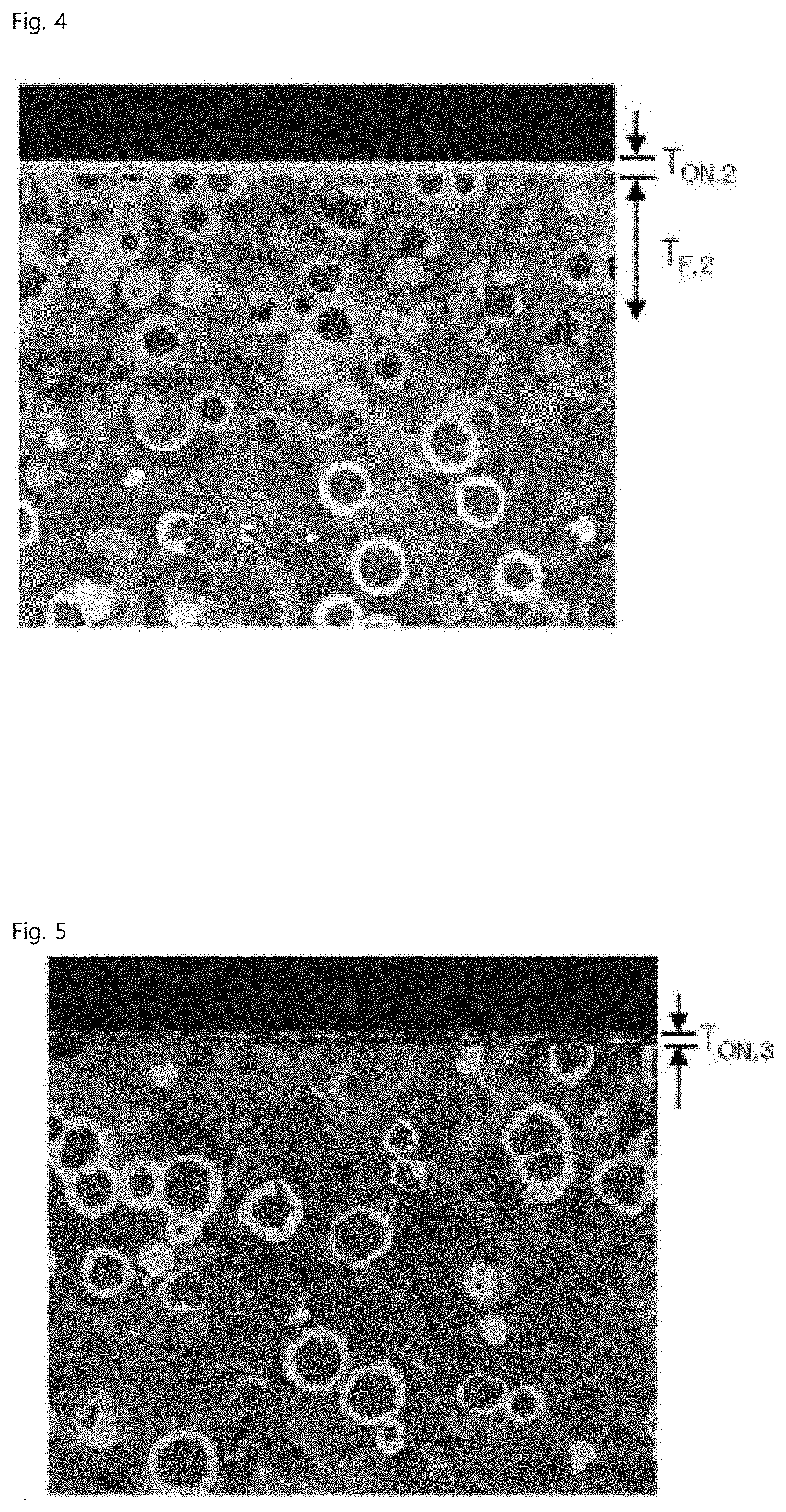
[0033] FIG. 4 shows an images of an exemplary microstructure of an exemplary spheroidal graphite cast iron heat-treated at a heating temperature less than the heating temperature of the heat treatment step for forming ferrite according to an exemplary embodiment of the present invention.
[0034] FIG. 5 shows an exemplary microstructure of a conventional spheroidal graphite cast iron.
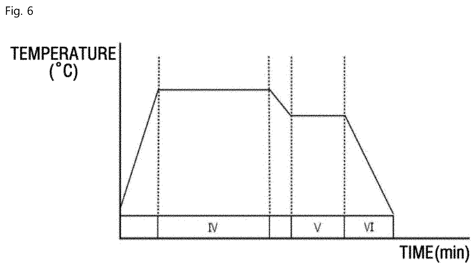
[0035] FIG. 6 is a detailed configuration view of an oxy-nitriding heat treatment step, according to an exemplary embodiment of the present invention.
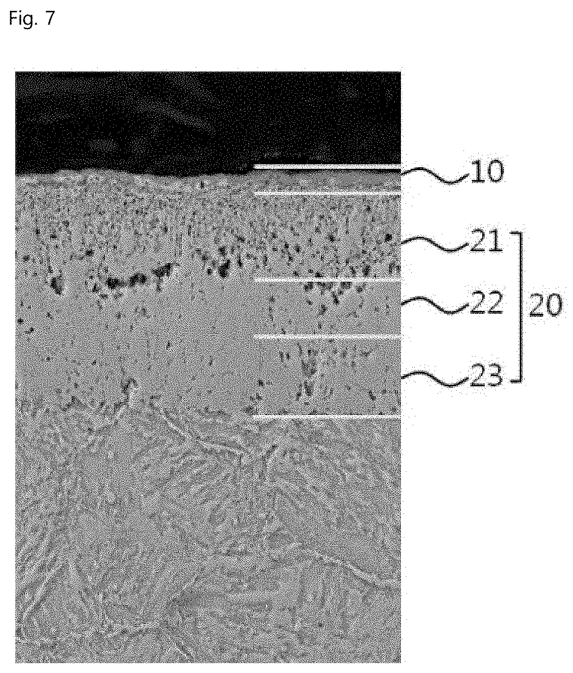
[0036] FIG. 7 illustrates a configuration of the uppermost surface of spheroidal graphite cast iron after the oxy-nitriding heat treatment step according to an exemplary embodiment of the present invention.
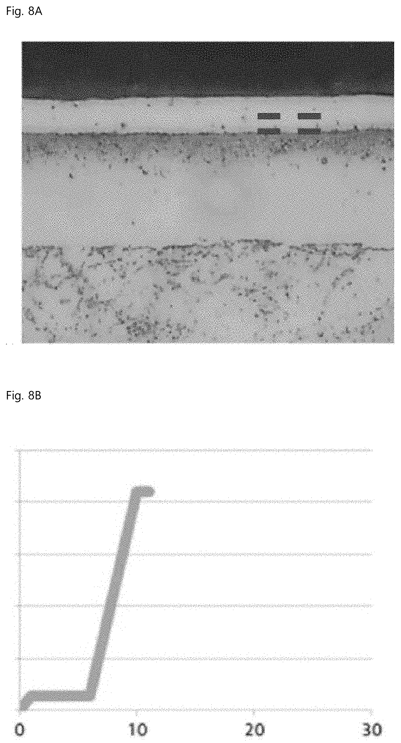
[0037] FIG. 8A is a microstructure of Comparative Example 2, and FIG. 8B is a result of evaluating seizure resistance of Comparative Example 2.
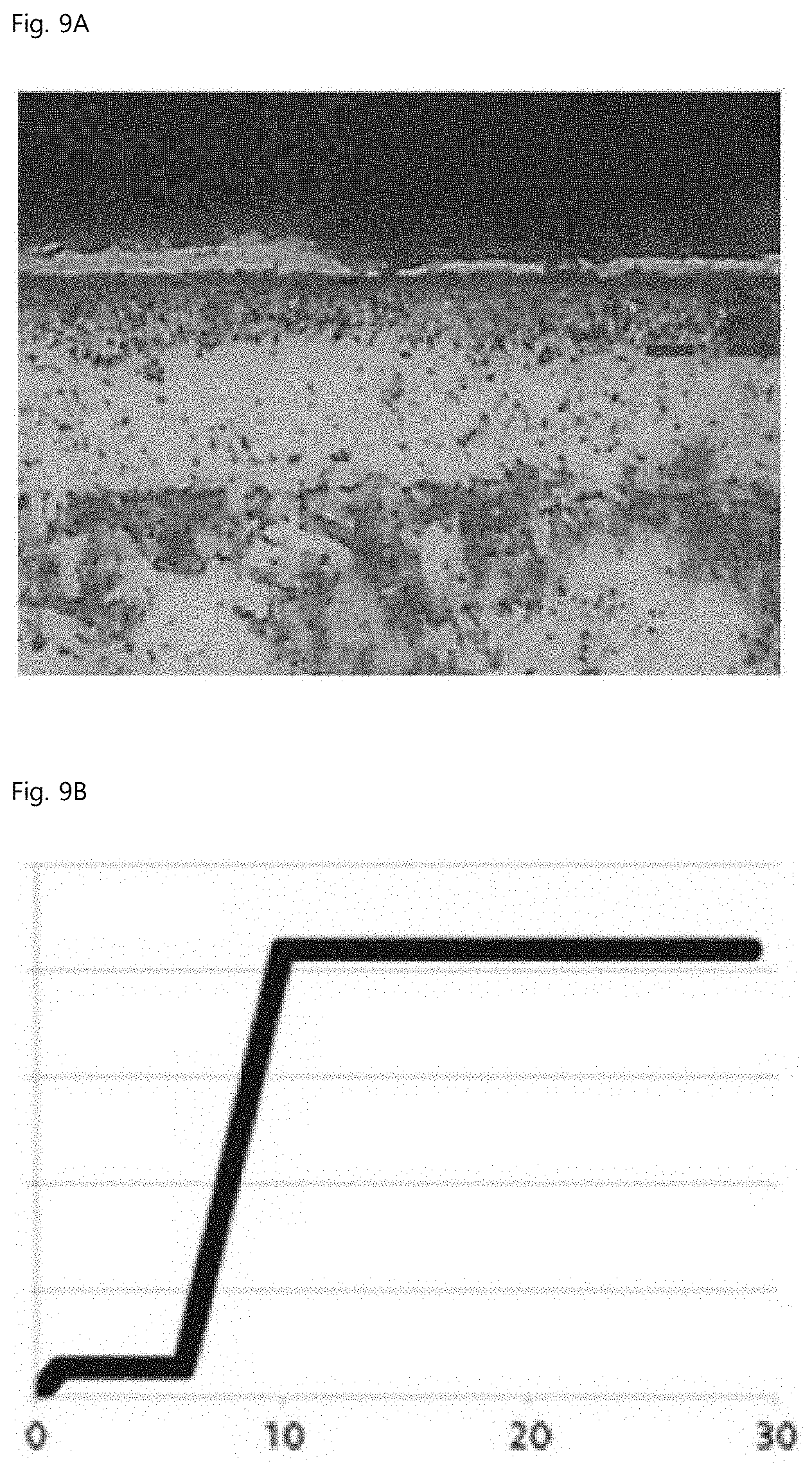
[0038] FIG. 9A is a microstructure of Example 2, and FIG. 9B is a result of evaluating seizure resistance of Example 2.
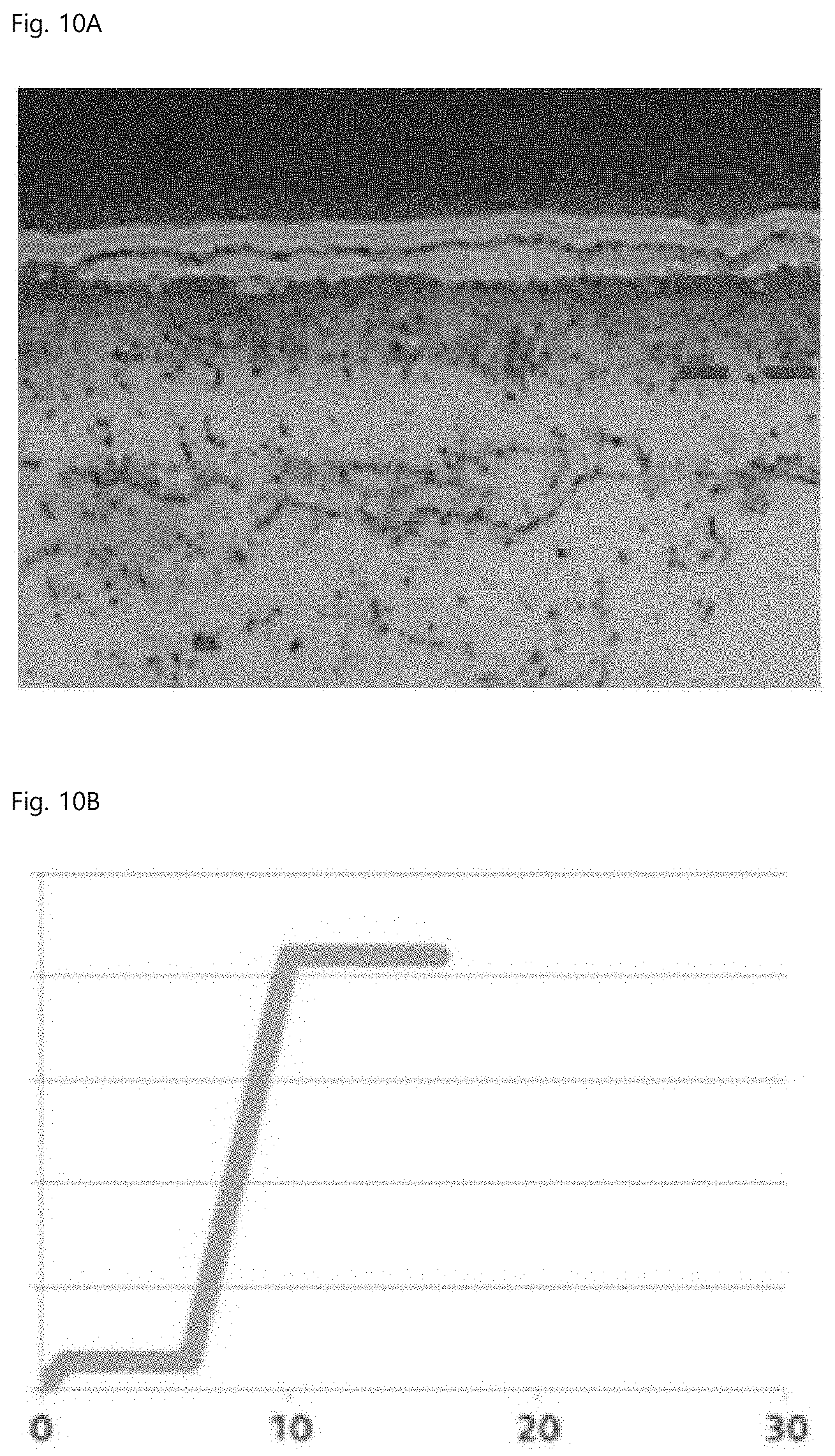
[0039] FIG. 10A is a microstructure of Comparative Example 3, and FIG. 10B is a result of evaluating seizure resistance of Comparative Example 3.
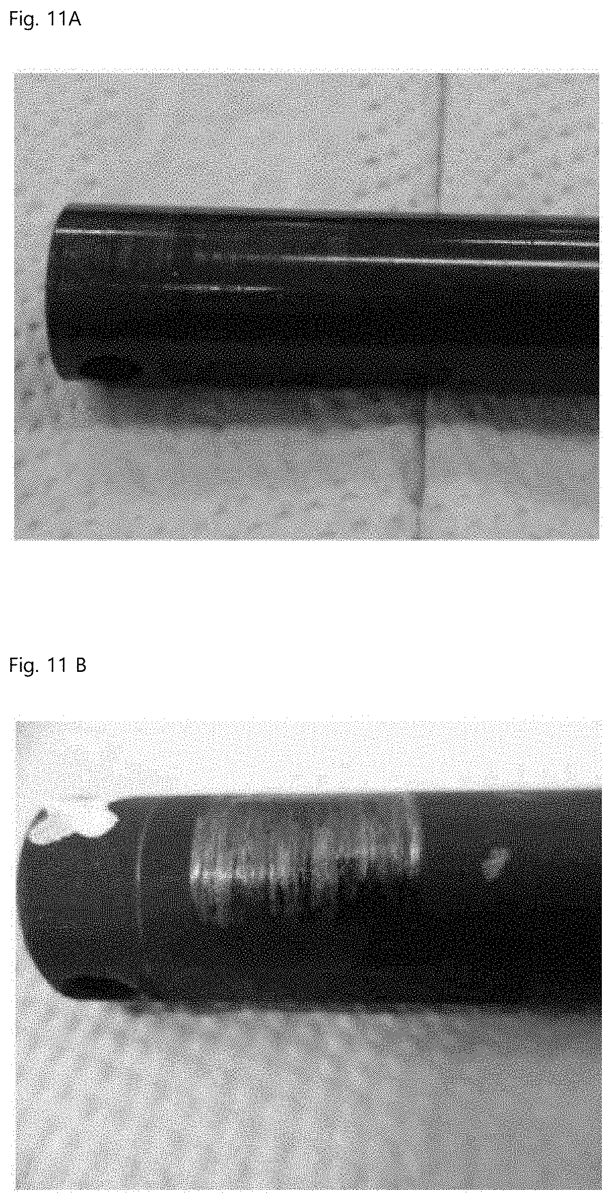
[0040] FIG. 11A is a photograph after evaluating seizure resistance of Example 2, and FIG. 11B is a photograph after evaluating seizure resistance of Comparative Example 3.
DETAILED DESCRIPTION OF THE EMBODIMENTS
[0041] Hereinafter, the present invention will be described in detail. However, the present invention is not limited or restricted by exemplary embodiments, objects and effects of the present invention will be naturally understood or become apparent from the following description, and the objects and effects of the present invention are not limited by only the following description. Further, in the description of the present invention, when it is determined that the detailed description for the publicly-known technology related to the present invention can unnecessarily obscure the gist of the present invention, the detailed description thereof will be omitted.
[0042] The terminology used herein is for the purpose of describing particular embodiments only and is not intended to be limiting. As used herein, the singular forms "a," "an" and "the" are intended to include the plural forms as well, unless the context clearly indicates otherwise. It will be further understood that the terms "comprise", "include", "have", etc. when used in this specification, specify the presence of stated features, regions, integers, steps, operations, elements and/or components but do not preclude the presence or addition of one or more other features, regions, integers, steps, operations, elements, components, and/or combinations thereof.
[0043] It is understood that the term "vehicle" or "vehicular" or other similar term as used herein is inclusive of motor vehicles in general such as passenger automobiles including sports utility vehicles (SUV), buses, trucks, various commercial vehicles, watercraft including a variety of boats and ships, aircraft, and the like, and includes hybrid vehicles, electric vehicles, plug-in hybrid electric vehicles, hydrogen-powered vehicles and other alternative fuel vehicles (e.g. fuels derived from resources other than petroleum). As referred to herein, a hybrid vehicle is a vehicle that has two or more sources of power, for example both gasoline-powered and electric-powered vehicles.
[0044] Further, unless specifically stated or obvious from context, as used herein, the term "about" is understood as within a range of normal tolerance in the art, for example within 2 standard deviations of the mean. "About" can be understood as within 10%, 9%, 8%, 7%, 6%, 5%, 4%, 3%, 2%, 1%, 0.5%, 0.1%, 0.05%, or 0.01% of the stated value. Unless otherwise clear from the context, all numerical values provided herein are modified by the term "about."
[0045] FIG. 1 shows an exemplary method for heat-treating the uppermost surface of spheroidal graphite cast iron according to an exemplary embodiment of the present invention. The method may include a heat treatment step for forming ferrite (S101) and an oxy-nitriding heat treatment step (S102).
[0046] Particularly, a proportion of pearlite which may be formed or present on the uppermost surface of spheroidal graphite cast iron may be decreased and a proportion of ferrite may be increased by performing a first heat treatment step for forming ferrite (S101) before performing a second heat treating step for oxy-nitriding (S102). Accordingly, during the oxy-nitriding heat treatment, a compound layer having a predetermined thickness or greater may be formed, as such abrasion resistance characteristics on the uppermost surface of spheroidal graphite cast iron may be provided, and a dense and uniform compound layer may be formed. Furthermore, a microstructure may be formed at the center of pearlite in the deep portion of spheroidal graphite cast iron, thereby having substantially improved toughness and strength.
[0047] The uppermost surface of spheroidal graphite cast iron as used herein refers to an area from the surface of cast iron to a depth of about 100 .mu.m. The compound layer having a predetermined thickness or greater may have a thickness of about 15 .mu.m or greater, or particularly have a thickness of about 15 to 30 .mu.m. The dense and uniform compound layer refers to that compound layer which is present while being distinguished from an oxide layer and does not crack or break across the compound layer.
[0048] FIG. 2 shows an exemplary first heat treatment step for forming ferrite according to an exemplary embodiment of the present invention. The first heat treatment step for forming ferrite may include heating spheroidal graphite cast iron to a first heat treatment temperature of about 940 to 1,060.degree. C. (I), maintaining the first heating treatment temperature (II), and air-cooling the spheroidal graphite cast iron.
[0049] Preferably, a uniform austenitized state may be formed through the heating step and the heating temperature maintaining step. When the uppermost surface of cast iron is austenitized, and then air-cooled, that residual stress may be removed due to processing and the like and crystal grains may be micronized, and ferrite may be formed on the uppermost surface, so that during the oxy-nitriding heat treatment, production of a nitrogen compound layer which is one configuration of the compound layer, for example, an epsilon (.epsilon.) phase and a gamma prime phase (.gamma.'), may be facilitated. In addition, the compound layer which is more dense and has a uniform thickness may be formed on the entire part surface.
[0050] The first heating treatment temperature of spheroidal graphite cast iron may be about 940 to 1,060.degree. C. When spheroidal graphite cast iron is heated at a temperature less than about 940.degree. C., and then air-cooled, the ferrite fraction in the uppermost surface of spheroidal graphite cast iron may be reduced to less than 60%, so that a compound layer having a predetermined thickness or more may not be secured. Accordingly, it is preferred that the heating temperature of spheroidal graphite cast iron may be 940.degree. C. or greater. Here, the unit "%", which is a unit of the ferrite fraction, means an area occupied by ferrite in spheroidal graphite cast iron. Meanwhile, when the heating temperature is about 1,060.degree. C. or less, a uniform austenite structure may be obtained because the austenite structure does not change into a melt. Accordingly, it is preferred that the maximum heating temperature is about 1,060.degree. C.
[0051] Preferably, the total time for performing the heating step (I) and the heating temperature maintaining step (II) may be about 80 to 100 minutes in order to secure a ferrite fraction of 60% or greater, and the time for performing the air-cooling step (III) may be of about 110 to 130 minutes.
[0052] Ferrite present in a diffusion layer remaining after the formation of the compound layer may improve elongation characteristics of a part and increase toughness of the part. Further, during the oxy-nitriding heat treatment, surface hardness and compressive residual stress may occur due to the invasive diffusion of carbon and nitrogen in the ferrite layer, and as a result, fatigue strength may be improved.
[0053] As a deep portion is changed from a structure in a medium pearlite state to a fine pearlite structure, the interlamellar spacing of pearlite may be decreased, so that the stiffness of a part may be improved because the sintering modification of the part is blocked.
[0054] FIG. 3 illustrates an exemplary microstructure of an exemplary spheroidal graphite cast iron heat-treated (hereinafter, referred to as Example 1) by the first heat treatment step for forming ferrite according to an exemplary embodiment of the present invention, and FIG. 4 illustrates a microstructure of spheroidal graphite cast iron heat-treated (hereinafter, referred to as Comparative Example 1) at a heating temperature less than the heating temperature of the heat treatment step for forming ferrite. FIG. 5 illustrates an exemplary microstructure of a conventional spheroidal graphite cast iron.
[0055] The following Table 1 summarizes the heating conditions and cooling conditions of spheroidal graphite cast iron illustrated in FIGS. 3 to 5. Table 2 summarizes the ferrite layer thicknesses, ferrite fractions, and oxynitride layer thicknesses of spheroidal graphite cast iron illustrated in FIGS. 3 to 5.
TABLE-US-00001 TABLE 1 Comparative Classification Example 1 Example 1 conventional Heating temperature 970.degree. C. 850.degree. C. X Heating time 100 minutes 80 minutes X Cooling method Air cooling Air cooling X Cooling time 120 minutes 120 minutes X
TABLE-US-00002 TABLE 2 Comparative Classification Example 1 Example 1 conventional Ferrite layer thickness 500 .mu.m 500 .mu.m -- (T.sub.F) Ferrite fraction 60~80% 30~50% 30% Oxynitride layer 20 .mu.m 6 .mu.m 4 .mu.m or less thickness (T.sub.ON)
[0056] As shown in Tables 1 and 2 and FIGS. 3 to 5, the ferrite layer thickness (T.sub.F1) in Example 1 was 500 .mu.m and the ferrite layer thickness (T.sub.F2) in Comparative Example 1 was also 500 .mu.m and was the same as the ferrite layer thickness in Example 1, but the ferrite fraction in Example 1 was 60 to 80%, which is higher than the ferrite fraction in Comparative Example 1, which was 30 to 50%, and accordingly, the thickness (T.sub.ON,1) of the oxynitride layer in Example 1 was 20 .mu.m, which was formed to be about 3.3 times larger than 6 .mu.m of the thickness (T.sub.ON,2) of the oxynitride layer in Comparative Example 1.
[0057] In the related art, the conventional spheroidal graphite cast iron which is not subjected to a heat treatment for forming ferrite has a ferrite fraction of 30%, and the conventional spheroidal graphite cast iron may not have a separate ferrite layer capable of being distinguished from the other portions in the spheroidal graphite cast iron. When as the ferrite layer is not provided, the thickness (T.sub.ON,3) of the oxynitride layer in the conventional cast iron may be also formed to be 4 .mu.m or less, which is less than the thickness (T.sub.ON,2) of the oxynitride layer in Comparative Example 1 and remarkably smaller than the thickness (T.sub.ON,1) of the oxynitride layer in Example 1.
[0058] Accordingly, in order to secure an oxynitride layer thickness of 15 .mu.m or greater, a ferrite fraction of 60 to 80% needs to be secured by decreasing the pearlite fraction on the surface of spheroidal graphite cast iron. Accordingly, a heat treatment step for forming ferrite may be performed without fail before the oxy-nitriding heat treatment, but the spheroidal graphite cast iron may be heated at the temperature of about 940 to 1,060.degree. C. for about 80 to 100 minutes, and then may be air-cooled for about 110 to 130 minutes.
[0059] FIG. 6 shows an exemplary second heat treating step for an oxy-nitriding heat treatment according to an exemplary embodiment of the present invention. The oxy-nitriding heat treatment step may include a gas nitrocarburizing step (IV), an oxidation treatment step (V), and a furnace cooling step (VI).
[0060] In order for a compound layer formed by the oxy-nitriding heat treatment step to have abrasion resistance characteristics, the fraction of a pore layer formed during the gas nitrocarburizing step may be controlled. The pore layer fraction refers to the pore layer thickness/the compound layer thickness, and the compound layer refers to a layer including a pore layer and a nitride compound layer consisting of a gamma prime phase (.gamma.') and an epsilon phase (.epsilon.).
[0061] When the pore layer fraction is less than about 25%, the oil-containing characteristics may be reduced, so that an effect of lowering frictional force may significantly be decreased. When the pore layer fraction is greater than 35%, the proportion of a soft porous layer may be increased, so that the entire hardness of the compound layer may be reduced, and as a result, abrasion resistance may deteriorate. Accordingly, the compound layer may include the pore layer fraction in about 25 to 35% in order to improve abrasion resistance.
[0062] The pore layer fraction may be affected by temperature and time during the nitrocarburizing treatment by introducing a gas, e.g., gas nitrocarburizing. Preferably, the nitrocarburizing treatment may be performed at an Ac1 temperature of about 723.degree. C. or less, or particularly, of about 550.degree. C. to 570.degree. C. for about 720 minutes to 1,200 minutes. When the temperature is less than about 550.degree. C. and the treatment time is greater than about 1,200 minutes, the pore layer fraction may be decreased to less than about 25%. In addition, when the temperature is greater than about 570.degree. C. and the treatment time is less than about 720 minutes, the pore layer fraction may be greater than about 35%. Preferably, the oxidation treatment step may be performed at about 560.degree. C. for about 30 minutes, and the furnace cooling step may be performed at about 60.degree. C. for about 150 minutes.
[0063] FIG. 7 illustrates an image of an exemplary uppermost surface of an exemplary spheroidal graphite cast iron after the second heat treating, i.e. oxy-nitriding heat treatment step. The uppermost surface of spheroidal graphite cast iron subjected to the heat treatment for forming ferrite and the oxy-nitriding heat treatment may include an oxidation layer 10 of Fe.sub.3O.sub.4 and a compound layer 20, the compound layer may have a thickness of about 15 .mu.m to 30 .mu.m, and the thickness may be uniform.
[0064] In order to improve the durability, the compound layer may be formed to have a thickness of about 15 .mu.m to 30 .mu.m, which may be uniform. When the thickness of the compound layer is formed to less than about 15 .mu.m, hardness of the compound layer may be reduced to less than about HV 600, so that when a part is operated, the compound layer may be easily peeled off, and as a result, the abrasion resistance function may be lost. Further, when the thickness of the compound layer is formed to be more than 30 .mu.m, the compound layer may have hardness enough for brittleness at a level of HV 1200 to occur, so that when a part is operated, fatigue failure occurs starting from the compound layer. Accordingly, it is preferred that the thickness of the compound layer may be of about 15 .mu.m to 30 .mu.m in order to allow the compound layer to have a hardness of HV 600 to 1000.
[0065] A pore layer 21 may be a porous layer of an oxynitride layer present below an oxidation layer 10, and may be relatively soft in the compound layer. The pore layer may contain a lubricating oil in a transmission, an engine, and the like, so that when a part is operated, frictional force may be reduced. Accordingly, when an optimal pore layer fraction is secured, an influence in which abrasion may occur by improving lubrication characteristics with the opponent part may be minimized. Accordingly, it is preferred that the pore layer fraction is about 25 to 35%.
[0066] Nitride compound layers 22 and 23 may include a gamma prime (.gamma.') phase 22 and an epsilon (.epsilon.) phase 23. The nitride compound layers 22 and 23 may be present below the pore layer 21, the gamma prime phase 22 may be located under the pore layer, and the epsilon phase 23 may be located below the gamma prime phase 22. Moreover, it is preferred that the proportion of the epsilon phase 23 in the nitride compound layers 22 and 23 may be about 80% or greater. Meanwhile, the unit % means an area occupied by the epsilon phase in the nitride compound layer.
[0067] During the gas nitrocarburizing treatment, the gamma prime phase 22 of Fe.sub.4N may be produced while the uppermost surface of spheroidal graphite cast iron begins to solid-solubilize nitrogen. The gamma prime phase 22 may be generally produced when the concentration of nitrogen is about 0.1% or greater, and from the time when the concentration of nitrogen is about 6% or greater, the epsilon phase 23 of Fe.sub.2,3N may be produced, and the epsilon phase 23 may also be transformed into the gamma prime phase 22.
[0068] The gamma prime phase 22 may affect the strength of a compound layer, and the epsilon phase 23 may affect the toughness. In general, the higher the proportion of the epsilon phase 23 is, the better corrosion resistance and abrasion resistance characteristics of cast iron may be obtained. In addition, the higher the proportion of the epsilon phase 23 is, the more nitrogen may be solid solubilized. When the epsilon phase 23 is about 80% or less, nitride may be relatively less solid solubilized on the surface and may be disadvantageous in terms of seizure resistance and abrasion resistance, so that the fraction of the epsilon phase 23 may be adjusted to about 80% or greater. Further, the fraction of the epsilon phase 23 may be adjusted to about 80% or greater in order to form a compound layer having a hardness of about HV 600 to 1000.
TABLE-US-00003 TABLE 3 Comparative Comparative Classification Example 2 Example 2 Example 3 K.sub.N 1.5 2.0 3.0 Temperature (.degree. C.) 540 570 590 Time (hr) 22 16 10 Pore layer fraction 10% 25% 40%
[0069] Table 3 summarizes the conditions of the gas nitrocarburizing step and the pore layer fractions in Comparative Example 2, Example 2, and Comparative Example 3. K.sub.N in Table 3 indicates a ratio of partial pressure of ammonia to partial pressure of hydrogen in a furnace during the oxy-nitriding heat treatment
( K N = P NH 3 P H 2 1 / 2 ) . ##EQU00001##
FIG. 8A is a microstructure of Comparative Example 2, and FIG. 8B is a result of evaluating seizure resistance of Comparative Example 2. FIG. 9A is a microstructure of Example 2, and FIG. 9B is a result of evaluating seizure resistance of Example 2. FIG. 10A is a microstructure of Comparative Example 3, and FIG. 10B is a result of evaluating seizure resistance of Comparative Example 3. The x-axis and the y-axis in FIGS. 8B, 9B, and 10B are time (min) and load (kg), respectively, and the interval of the load is 500 kg.
[0070] The evaluation of seizure resistance and abrasion resistance is based on the FALEX PIN & VEE BLOCK test, based on ASTM D3233A. A load is applied to the middle pin through right and left V-BLOCKs, and when seizure occurs between a pin rotating at high speed and a block, the test is terminated while the BRASS LOCKING PIN is broken. By comparison of the time when breakage of the fixed pin occurs, the seizure resistances of test specimens can be compared. In other words, the times when the maximum load is maintained are compared.
[0071] As shown in Table 3 and FIGS. 8 to 10, the fixed pin was broken after a maximum load of 2,100 kg was maintained for 1 minute in Comparative Example 2, whereas the same maximum load was maintained for 20 minutes or more, but the fixed pin was not broken in Example 2, and the fixed pin was broken after the same maximum load was maintained for 6 minutes in Comparative Example 3. Meanwhile, even though the case is not included in Table 3, when K.sub.N=2.7 and the temperature and time of the gas nitrocarburizing step were 570.degree. C. and 720 minutes, respectively, the pore layer fraction was 35%, and a result was at a level equivalent to Example 2 in Table 3.
[0072] FIG. 11A is a photograph after evaluating seizure resistance of Example 2, and FIG. 11B is a photograph after evaluating seizure resistance of Comparative Example 3. As shown in FIGS. 11A and 11B, it can be seen that abrasion and seizure do not occur in Example 2, whereas abrasion and seizure occur in Comparative Example 3.
[0073] As demonstrated in Comparative Example 2, Example 2, and Comparative Example 3, in order to improve abrasion resistance of cast iron, a pore layer fraction of about 25% or greater may be secured, but a pore layer fraction of less than 40%, or particularly of about 35% or less may be secured.
[0074] According to various exemplary embodiments of the present invention, the cast iron may be applied to a control finger, but is not limited thereto, and parts requiring high strength while requiring the durability as compared to the conventional cast iron may be subjected to a complex oxy-nitriding heat treatment. Since cast iron is already used in various parts of an automobile, such as a diff case or a control body, a compound layer having a thickness of about 15 .mu.m or greater may be formed on the surface layer by subjecting spheroidized graphite cast iron at the FCD450 to 700 level to the complex oxy-nitriding heat treatment such as the invention.
[0075] The present invention has been described in detail through representative Examples, but it is to be understood by a person with ordinary skill in the art to which the present invention pertains that various modifications are possible in the above-described Examples within the range not departing from the scope of the present invention. Therefore, the scope of the present invention should not be limited to the above-described Examples but should be determined by not only the claims to be described below but also all the changes or modified forms derived from the claims and the equivalent concept thereof.
* * * * *
D00001
D00002
D00003
D00004
D00005
D00006
D00007
D00008
D00009
XML
uspto.report is an independent third-party trademark research tool that is not affiliated, endorsed, or sponsored by the United States Patent and Trademark Office (USPTO) or any other governmental organization. The information provided by uspto.report is based on publicly available data at the time of writing and is intended for informational purposes only.
While we strive to provide accurate and up-to-date information, we do not guarantee the accuracy, completeness, reliability, or suitability of the information displayed on this site. The use of this site is at your own risk. Any reliance you place on such information is therefore strictly at your own risk.
All official trademark data, including owner information, should be verified by visiting the official USPTO website at www.uspto.gov. This site is not intended to replace professional legal advice and should not be used as a substitute for consulting with a legal professional who is knowledgeable about trademark law.