Power Seat Track Assembly
TEER; Antal ; et al.
U.S. patent application number 16/737991 was filed with the patent office on 2020-07-09 for power seat track assembly. This patent application is currently assigned to FISHER & COMPANY, INCORPORATED. The applicant listed for this patent is FISHER & COMPANY, INCORPORATED. Invention is credited to Burckhard BECKER, Sapan M. POPTANI, Antal TEER.
| Application Number | 20200215936 16/737991 |
| Document ID | / |
| Family ID | 71404754 |
| Filed Date | 2020-07-09 |


| United States Patent Application | 20200215936 |
| Kind Code | A1 |
| TEER; Antal ; et al. | July 9, 2020 |
Power Seat Track Assembly
Abstract
A power seat track assembly may include an elongated first rail, a second rail, a motor assembly, and a power-transfer assembly. The second rail may engage the first rail and may be movable along a length of the first rail. The motor assembly may be mounted to the second rail and may be operable to drive the second rail along the length of the first rail. The power-transfer assembly may include a first component mounted to the first rail and a second component mounted to the second rail. The first component may wirelessly transmit power to the second component. The second component may be electrically connected to the motor assembly to provide electrical current to the motor assembly.
| Inventors: | TEER; Antal; (Harrison Township, MI) ; BECKER; Burckhard; (Solingen, DE) ; POPTANI; Sapan M.; (Northville, MI) | ||||||||||
| Applicant: |
|
||||||||||
|---|---|---|---|---|---|---|---|---|---|---|---|
| Assignee: | FISHER & COMPANY,
INCORPORATED St. Clair Shores MI |
||||||||||
| Family ID: | 71404754 | ||||||||||
| Appl. No.: | 16/737991 | ||||||||||
| Filed: | January 9, 2020 |
Related U.S. Patent Documents
| Application Number | Filing Date | Patent Number | ||
|---|---|---|---|---|
| 62790245 | Jan 9, 2019 | |||
| Current U.S. Class: | 1/1 |
| Current CPC Class: | B60N 2002/0236 20130101; F16H 19/043 20130101; B60N 2/0232 20130101; B60N 2/067 20130101; B60N 2/0707 20130101 |
| International Class: | B60N 2/02 20060101 B60N002/02; B60N 2/07 20060101 B60N002/07; F16H 19/04 20060101 F16H019/04 |
Claims
1. A vehicle seat assembly comprising: a vehicle seat; an elongated first rail mounted to a vehicle cabin floor; a second rail engaging the first rail and movable along a length of the first rail; a motor assembly mounted to the second rail and operable to drive the second rail along the length of the first rail; and a power-transfer assembly including a first component mounted to the first rail and a second component mounted to the second rail, wherein the first component wirelessly transmits power to the second component, and wherein the second component is electrically connected to the motor assembly to provide electrical current to the motor assembly.
2. The vehicle seat assembly of claim 1, wherein the first rail, the motor assembly, the power-transfer assembly, and a portion of the second rail are mounted below the vehicle cabin floor.
3. The vehicle seat assembly of claim 2, wherein the second rail includes a bracket portion that extends through an opening in the vehicle cabin floor.
4. The vehicle seat assembly of claim 1, further comprising an additional second rail and an additional motor assembly mounted to the additional second rail, wherein the power-transfer assembly includes an additional second component mounted to the additional second rail and electrically connected to the additional motor assembly, and wherein the motor assemblies are operable to independently drive the second rails along the length of the first rail.
5. The vehicle seat assembly of claim 1, wherein the first component is an elongated power-transfer rail, and wherein the second components are power-transfer blocks.
6. The vehicle seat assembly of claim 1, wherein the first rail is fixed relative to the vehicle cabin floor, and wherein the second rails support vehicle seats for movement relative to the first rail and the vehicle cabin floor.
7. The vehicle seat assembly of claim 6, wherein the motor assembly includes a pinion that is rotatable about a rotational axis, and wherein a rack is fixed to the first rail and includes a plurality of teeth that meshingly engage the pinion.
8. The vehicle seat assembly of claim 7, wherein the rack includes a first aperture, wherein the first rail includes a second aperture, and wherein a fastener extends through the first and second apertures and into a third aperture in the vehicle cabin floor.
9. The vehicle seat assembly of claim 8, wherein the teeth of the rack are formed on a lateral surface of the rack, and wherein the rotational axis of the pinion is parallel to a longitudinal axis of the fastener.
10. The vehicle seat assembly of claim 9, wherein the rotational axis of the pinion is perpendicular to the vehicle cabin floor and is perpendicular to a direction in which the second rail is movable relative to the first rail.
11. A power seat track assembly comprising: an elongated first rail; a second rail engaging the first rail and movable along a length of the first rail; a motor assembly mounted to the second rail and operable to drive the second rail along the length of the first rail; and a power-transfer assembly including a first component mounted to the first rail and a second component mounted to the second rail, wherein the first component wirelessly transmits power to the second component, and wherein the second component is electrically connected to the motor assembly to provide electrical current to the motor assembly.
12. The power seat track assembly of claim 11, wherein the first rail, the motor assembly, the power-transfer assembly, and a portion of the second rail are mounted below a vehicle cabin floor.
13. The power seat track assembly of claim 12, wherein the second rail includes a bracket portion that extends through an opening in the vehicle cabin floor.
14. The power seat track assembly of claim 11, further comprising an additional second rail and an additional motor assembly mounted to the additional second rail, wherein the power-transfer assembly includes an additional second component mounted to the additional second rail and electrically connected to the additional motor assembly, and wherein the motor assemblies are operable to independently drive the second rails along the length of the first rail.
15. The power seat track assembly of claim 11, wherein the first component is an elongated power-transfer rail, and wherein the second components are power-transfer blocks.
16. The power seat track assembly of claim 15, wherein the first rail is fixed relative to a vehicle cabin floor, and wherein the second rail supports a vehicle seat for movement relative to the first rail and the vehicle cabin floor.
17. The power seat track assembly of claim 16, wherein the motor assembly includes a pinion that is rotatable about a rotational axis, and wherein a rack is fixed to the first rail and includes a plurality of teeth that meshingly engage the pinion.
18. The power seat track assembly of claim 17, wherein the rack includes a first aperture, wherein the first rail includes a second aperture, and wherein a fastener extends through the first and second apertures and into a third aperture in the vehicle cabin floor.
19. The power seat track assembly of claim 18, wherein the teeth of the rack are formed on a lateral surface of the rack, and wherein the rotational axis of the pinion is parallel to a longitudinal axis of the fastener.
20. The power seat track assembly of claim 19, wherein the rotational axis of the pinion is perpendicular to the vehicle cabin floor and is perpendicular to a direction in which the second rail is movable relative to the first rail.
Description
CROSS-REFERENCE TO RELATED APPLICATIONS
[0001] This application claims the benefit of U.S. Provisional Application No. 62/790,245, filed on Jan. 9, 2019. The entire disclosure of the above application is incorporated herein by reference.
FIELD
[0002] The present disclosure relates to a power seat track assembly for a vehicle seat assembly.
SUMMARY
[0003] This section provides a general summary of the disclosure, and is not a comprehensive disclosure of its full scope or all of its features.
[0004] In one form, the present disclosure provides a vehicle seat assembly that may include a vehicle seat and a power seat track assembly. The power seat track assembly may include an elongated first rail, a second rail, a motor assembly, and a power-transfer assembly. The first rail may be mounted to a vehicle cabin floor. The second rail may engage the first rail and may be movable along a length of the first rail. The motor assembly may be mounted to the second rail and is operable to drive the second rail along the length of the first rail. The power-transfer assembly may include a first component mounted to the first rail and a second component mounted to the second rail. The first component may wirelessly transmits power to the second component. The second component is electrically connected to the motor assembly to provide electrical current to the motor assembly.
[0005] In some configurations of the vehicle seat assembly of the above paragraph, the first rail, the motor assembly, the power-transfer assembly, and a portion of the second rail are mounted below the vehicle cabin floor.
[0006] In some configurations of the vehicle seat assembly of any of the above paragraphs, the second rail includes a bracket portion that extends through an opening in the vehicle cabin floor.
[0007] In some configurations, the vehicle seat assembly of any of the above paragraphs includes an additional second rail and an additional motor assembly mounted to the additional second rail. The power-transfer assembly may include an additional second component mounted to the additional second rail and electrically connected to the additional motor assembly. The motor assemblies may be operable to independently drive the second rails along the length of the first rail.
[0008] In some configurations of the vehicle seat assembly of any of the above paragraphs, the first component is an elongated power-transfer rail, and the second components are power-transfer blocks.
[0009] In some configurations of the vehicle seat assembly of any of the above paragraphs, the first rail is fixed relative to the vehicle cabin floor, and the second rails support vehicle seats for movement relative to the first rail and the vehicle cabin floor.
[0010] In some configurations of the vehicle seat assembly of any of the above paragraphs, the motor assembly includes a pinion that is rotatable about a rotational axis. A rack may be fixed to the first rail and includes a plurality of teeth that meshingly engage the pinion.
[0011] In some configurations of the vehicle seat assembly of any of the above paragraphs, the rack includes a first aperture, and the first rail includes a second aperture. A fastener may extend through the first and second apertures and into a third aperture in the vehicle cabin floor.
[0012] In some configurations of the vehicle seat assembly of any of the above paragraphs, the teeth of the rack are formed on a lateral surface of the rack. The rotational axis of the pinion may be parallel to a longitudinal axis of the fastener.
[0013] In some configurations of the vehicle seat assembly of any of the above paragraphs, the rotational axis of the pinion is perpendicular to the vehicle cabin floor and is perpendicular to a direction in which the second rail is movable relative to the first rail.
[0014] In another form, the present disclosure provides a power seat track assembly that may include an elongated first rail, a second rail, a motor assembly, and a power-transfer assembly. The second rail may engage the first rail and may be movable along a length of the first rail. The motor assembly may be mounted to the second rail and may be operable to drive the second rail along the length of the first rail. The power-transfer assembly may include a first component mounted to the first rail and a second component mounted to the second rail. The first component may wirelessly transmit power to the second component. The second component may be electrically connected to the motor assembly to provide electrical current to the motor assembly.
[0015] In some configurations of the power seat track assembly of the above paragraph, the first rail, the motor assembly, the power-transfer assembly, and a portion of the second rail are mounted below a cabin floor of a vehicle.
[0016] In some configurations of the power seat track assembly of any of the above paragraphs, the second rail includes a bracket portion that extends through an elongated opening in the cabin floor.
[0017] In some configurations, the power seat track assembly of any of the above paragraphs may also include an additional second rail and an additional motor assembly mounted to the additional second rail.
[0018] In some configurations of the power seat track assembly of any of the above paragraphs, the power-transfer assembly may include an additional second component mounted to the additional second rail and electrically connected to the additional motor assembly.
[0019] In some configurations of the power seat track assembly of any of the above paragraphs, the motor assemblies may be operable to independently drive the second rails along the length of the first rail.
[0020] In some configurations of the power seat track assembly of any of the above paragraphs, the first component is an elongated power-transfer rail.
[0021] In some configurations of the power seat track assembly of any of the above paragraphs, the second components are power-transfer blocks.
[0022] In some configurations of the power seat track assembly of any of the above paragraphs, the first rail is fixed relative to the cabin floor, and the second rails support vehicle seats for movement relative to the first rail and the cabin floor.
[0023] In some configurations of the power seat track assembly of any of the above paragraphs, the motor assembly includes a pinion that is rotatable about a rotational axis, and a rack is fixed to the first rail and includes a plurality of teeth that meshingly engage the pinion.
[0024] In some configurations of the power seat track assembly of any of the above paragraphs, the rack includes a first aperture, and the first rail includes a second aperture. A fastener may extend through the first and second apertures and into a third aperture in the vehicle cabin floor.
[0025] In some configurations of the power seat track assembly of any of the above paragraphs, the teeth of the rack are formed on a lateral surface of the rack. The rotational axis of the pinion may be parallel to a longitudinal axis of the fastener.
[0026] In some configurations of the power seat track assembly of any of the above paragraphs, the rotational axis of the pinion is perpendicular to the vehicle cabin floor and is perpendicular to a direction in which the second rail is movable relative to the first rail.
[0027] Further areas of applicability will become apparent from the description provided herein. The description and specific examples in this summary are intended for purposes of illustration only and are not intended to limit the scope of the present disclosure.
DRAWINGS
[0028] The drawings described herein are for illustrative purposes only of selected embodiments and not all possible implementations, and are not intended to limit the scope of the present disclosure.
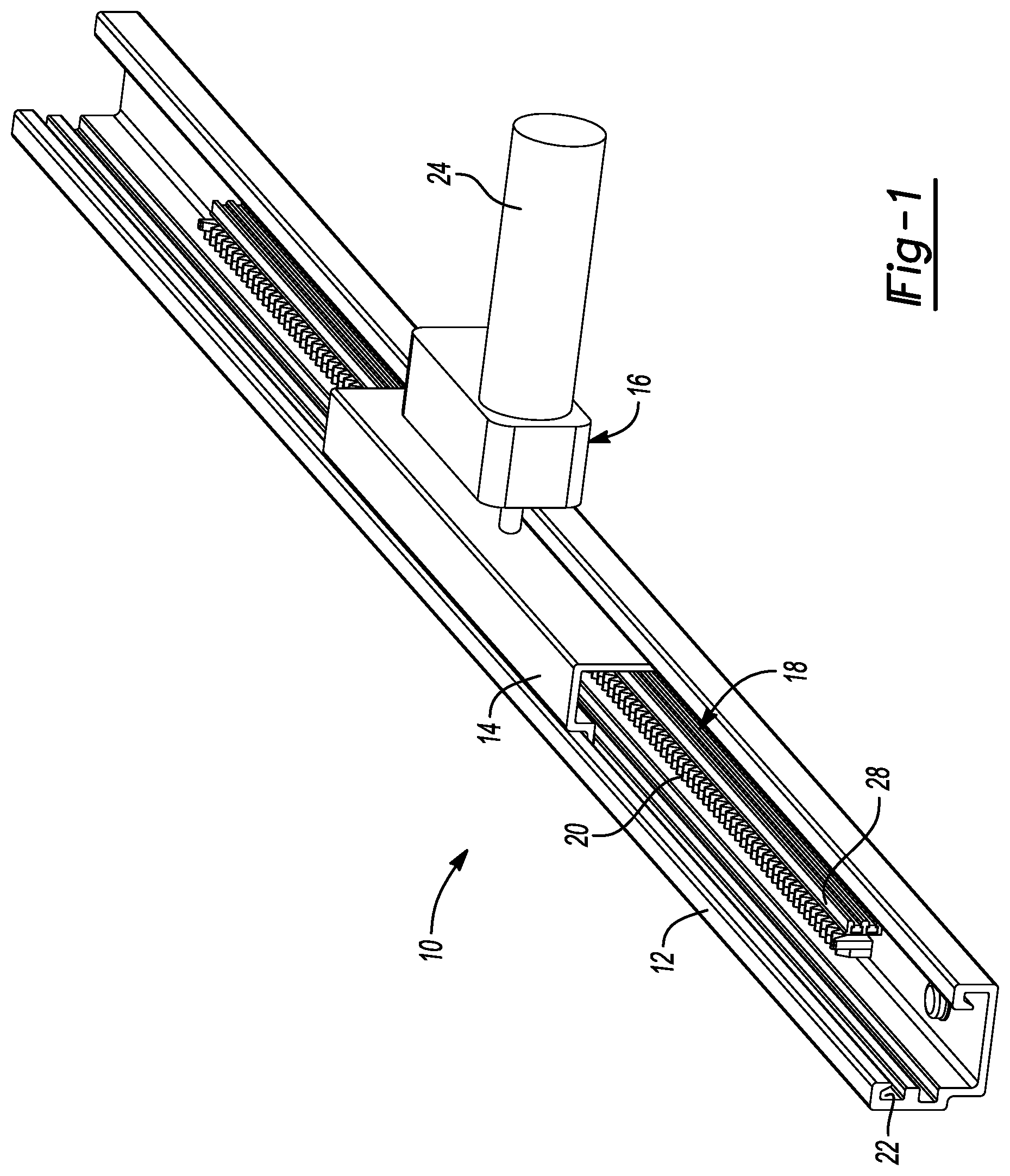
[0029] FIG. 1 is a perspective view of a power seat track assembly for a vehicle seat assembly;
[0030] FIG. 2 is another perspective view of the power seat track assembly of FIG. 1;
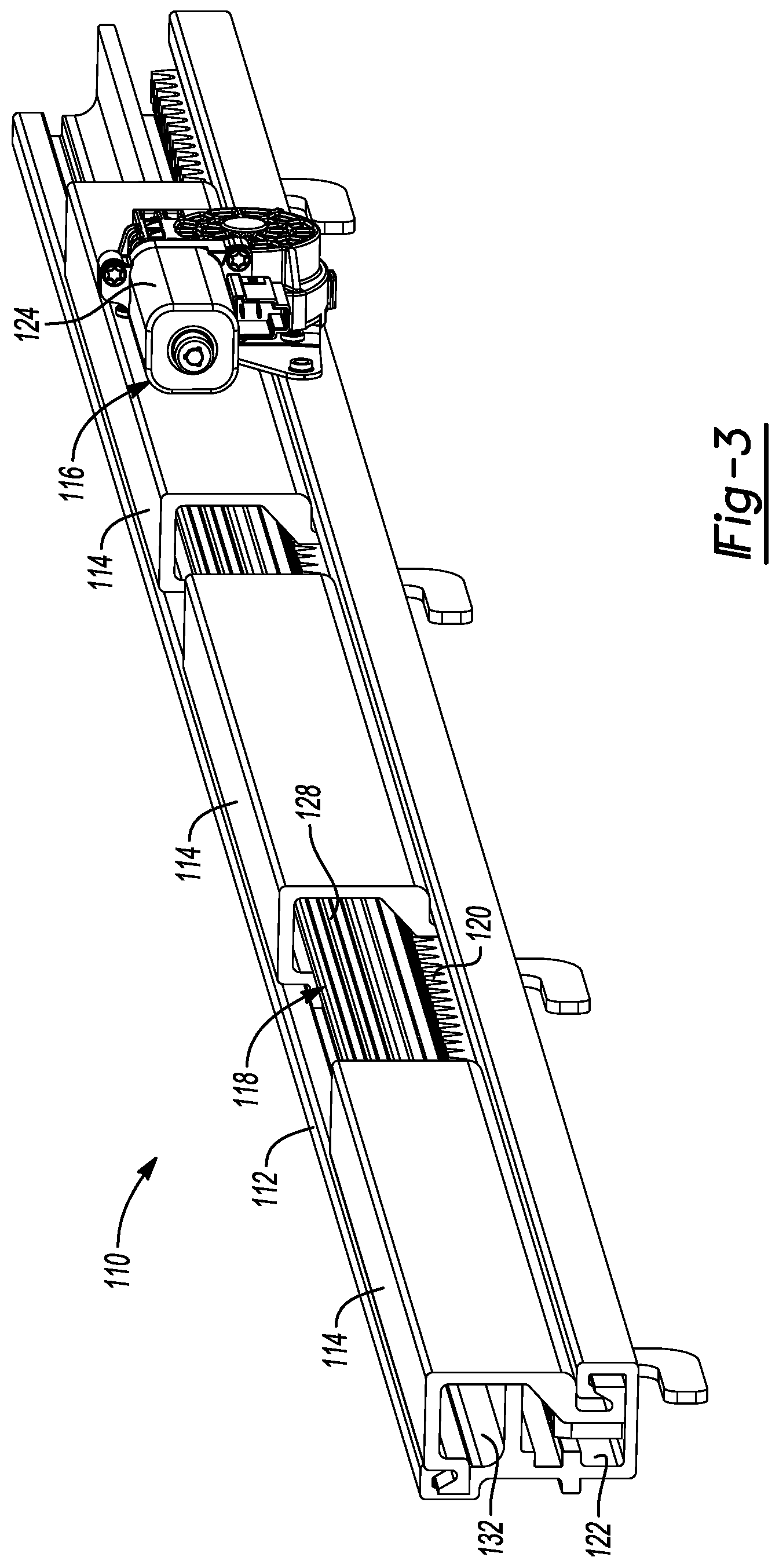
[0031] FIG. 3 is a perspective view of another power seat track assembly for a vehicle seat assembly;
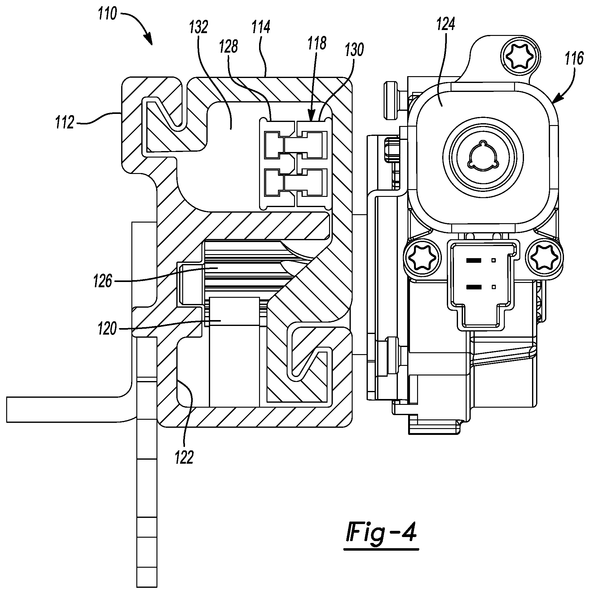
[0032] FIG. 4 is a cross-sectional view of the power seat track assembly of FIG. 3;
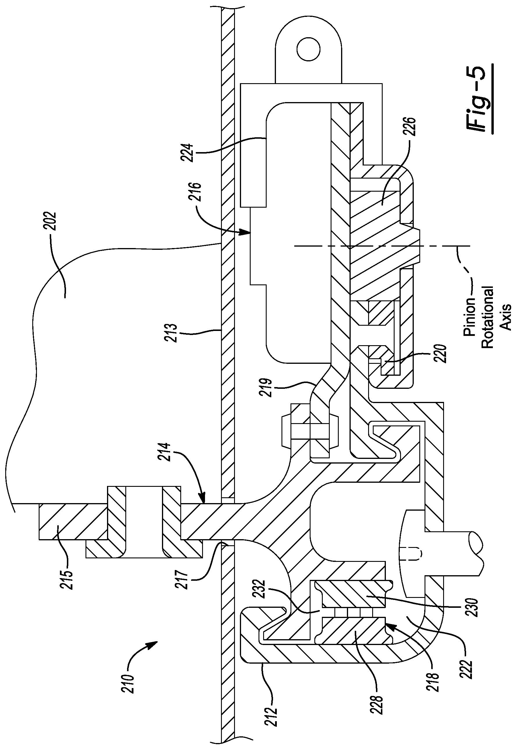
[0033] FIG. 5 is a cross-sectional view of another power seat track assembly for a vehicle seat assembly;
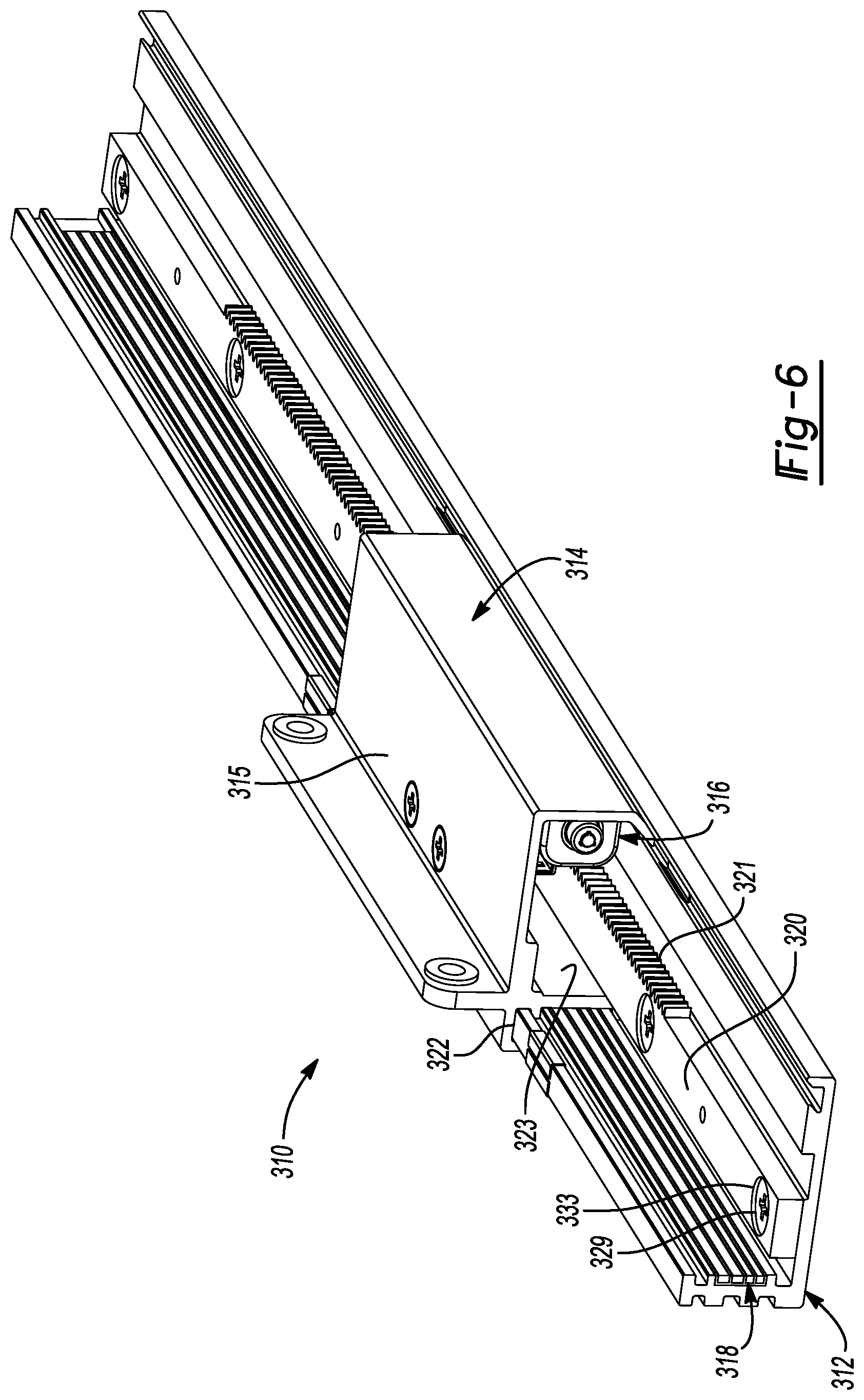
[0034] FIG. 6 is a partial perspective view of another power seat track assembly for a vehicle seat assembly;
[0035] FIG. 7 is a side view of the power seat track assembly of FIG. 6; and
[0036] FIG. 8 is another partial perspective view of the power seat track assembly of FIG. 6.
[0037] Corresponding reference numerals indicate corresponding parts throughout the several views of the drawings.
DETAILED DESCRIPTION
[0038] Example embodiments will now be described more fully with reference to the accompanying drawings.
[0039] Example embodiments are provided so that this disclosure will be thorough, and will fully convey the scope to those who are skilled in the art. Numerous specific details are set forth such as examples of specific components, devices, and methods, to provide a thorough understanding of embodiments of the present disclosure. It will be apparent to those skilled in the art that specific details need not be employed, that example embodiments may be embodied in many different forms and that neither should be construed to limit the scope of the disclosure. In some example embodiments, well-known processes, well-known device structures, and well-known technologies are not described in detail.
[0040] The terminology used herein is for the purpose of describing particular example embodiments only and is not intended to be limiting. As used herein, the singular forms "a," "an," and "the" may be intended to include the plural forms as well, unless the context clearly indicates otherwise. The terms "comprises," "comprising," "including," and "having," are inclusive and therefore specify the presence of stated features, integers, steps, operations, elements, and/or components, but do not preclude the presence or addition of one or more other features, integers, steps, operations, elements, components, and/or groups thereof. The method steps, processes, and operations described herein are not to be construed as necessarily requiring their performance in the particular order discussed or illustrated, unless specifically identified as an order of performance. It is also to be understood that additional or alternative steps may be employed.
[0041] When an element or layer is referred to as being "on," "engaged to," "connected to," or "coupled to" another element or layer, it may be directly on, engaged, connected or coupled to the other element or layer, or intervening elements or layers may be present. In contrast, when an element is referred to as being "directly on," "directly engaged to," "directly connected to," or "directly coupled to" another element or layer, there may be no intervening elements or layers present. Other words used to describe the relationship between elements should be interpreted in a like fashion (e.g., "between" versus "directly between," "adjacent" versus "directly adjacent," etc.). As used herein, the term "and/or" includes any and all combinations of one or more of the associated listed items.
[0042] Although the terms first, second, third, etc. may be used herein to describe various elements, components, regions, layers and/or sections, these elements, components, regions, layers and/or sections should not be limited by these terms. These terms may be only used to distinguish one element, component, region, layer or section from another region, layer or section. Terms such as "first," "second," and other numerical terms when used herein do not imply a sequence or order unless clearly indicated by the context. Thus, a first element, component, region, layer or section discussed below could be termed a second element, component, region, layer or section without departing from the teachings of the example embodiments.
[0043] Spatially relative terms, such as "inner," "outer," "beneath," "below," "lower," "above," "upper," and the like, may be used herein for ease of description to describe one element or feature's relationship to another element(s) or feature(s) as illustrated in the figures. Spatially relative terms may be intended to encompass different orientations of the device in use or operation in addition to the orientation depicted in the figures. For example, if the device in the figures is turned over, elements described as "below" or "beneath" other elements or features would then be oriented "above" the other elements or features. Thus, the example term "below" can encompass both an orientation of above and below. The device may be otherwise oriented (rotated 90 degrees or at other orientations) and the spatially relative descriptors used herein interpreted accordingly.
[0044] With reference to FIGS. 1 and 2, a power seat track assembly 10 is provided that may include a first rail 12, a second rail 14, a motor assembly 16, and a power-transfer assembly 18 (only partially shown in FIGS. 1 and 2). A pair (or multiple pairs) of the power seat track assemblies 10 (only one power seat track assembly 10 is shown in the figures) may be installed in or on a cabin floor of vehicle (e.g., an autonomous automotive vehicle or a human-driven automotive vehicle) and may support one or more vehicle seats (not shown). The power seat track assemblies 10 are operable to selectively move the one or more vehicle seats relative to the cabin floor (e.g., in fore-aft directions).
[0045] The first rail 12 may be an elongated, extruded rail and may be fixed relative to the cabin floor (e.g., fixedly mounted above or below the cabin floor). A rack 20 having a plurality of rack teeth may be attached to or formed on the first rail 12. A cross-sectional shape of the first rail 12 defines a channel 22 that movably receives a portion of the second rail 14. That is, a portion of the second rail 14 includes a cross-sectional shape that fits within the channel 22 to allow the second rail 14 to move (e.g., slide) along the length of the first rail 12. A vehicle seat may be mounted to the second rail 14 (i.e., the vehicle seat may be mounted to the second rail 14 of each power seat track assembly 10 of a pair of power seat track assemblies 10).
[0046] The motor assembly 16 may be mounted to the second rail 14 and may include a motor 24 and a pinion 26 (FIG. 2). The pinion 26 may be meshingly engaged with the rack 20. The motor 24 may drive rotation of the pinion 26 relative to the rack 20 to move the second rail 14 along the length of the first rail 12.
[0047] The power-transfer assembly 18 can be any suitable type of wireless power-transfer assembly such as an inductive power transfer assembly, for example. The power-transfer assembly 18 may include an elongated power-transfer rail 28 and a power-transfer block 30. The power-transfer rail 28 may be fixed to the first rail 12 and may extend along much of (or the entire) length of the first rail 12. The power-transfer block 30 may be mounted to the second rail 14 and may move with the second rail 14 relative to the power-transfer rail 28 and the first rail 12 during operation of the motor assembly 16. The power-transfer rail 28 may be connected via wires to a source of electrical power (e.g., a battery). Power may be wirelessly transferred from the power-transfer rail 28 to the power-transfer block 30 (via induction, for example) even while the power-transfer block 30 moves along the length of the power-transfer rail 28. The power-transfer block 30 may be connected via wires to the motor 24 to provide electrical current to the motor 24.
[0048] In some configurations, a pair of power seat track assemblies 10 may movably support multiple vehicle seats (e.g., a front row seat, a second row seat, a third row seat, etc.). That is, each power seat track assembly 10 may include more than one second rail 14 engaging a single first rail 12. Each second rail 14 may be independently driven by a respective motor assembly 16 and can support a respective vehicle seat. In this manner, multiple vehicle seats can be independent moved along a single first rail 12 (or a single pair of first rails 12). Each second rail 14 may also include a respective power-transfer block 30 that is movable along the power-transfer rail 28. Each power-transfer block 30 can independently receive power from the power-transfer rail 28. This significantly reduces length of wire harnesses powering the motor assemblies 16.
[0049] With reference to FIGS. 3 and 4, another power seat track assembly 110 is provided that may include a first rail 112, a plurality of second rails 114, a plurality of motor assemblies 116 (only one of which is shown), and a power-transfer assembly 118. As described above with respect to the power seat track assembly 10, a pair (or multiple pairs) of the power seat track assemblies 110 (only one power seat track assembly 110 is shown in the figures) may be installed in or on a cabin floor of vehicle (e.g., an autonomous automotive vehicle or a human-driven automotive vehicle) and may support a plurality of vehicle seats (not shown). The power seat track assemblies 110 are operable to independently move the vehicle seats relative to the cabin floor (e.g., in fore-aft directions).
[0050] The first rail 112 and the second rails 114 can be generally similar to the first rail 12 and second rail 14 described above. That is, the first rail 112 may be an elongated, extruded rail and may be fixed relative to the cabin floor (e.g., fixedly mounted above or below the cabin floor). A rack 120 having a plurality of rack teeth may be attached to or formed on the first rail 112. A cross-sectional shape of the first rail 112 defines a channel 122 that movably receives a portion of each of the second rails 114. That is, a portion of each of the second rails 114 includes a cross-sectional shape that fits within the channel 122 to allow the second rails 114 to move (e.g., slide or move along bearings) along the length of the first rail 112. A vehicle seat may be mounted to each of the second rails 114 (i.e., each vehicle seat may be mounted to a respective one of the second rails 114 of each power seat track assembly 110 of a pair of power seat track assemblies 110).
[0051] Each of the motor assemblies 116 may be mounted to a respective one of the second rails 114 and each may include a motor 124 and a pinion 126 (FIG. 4). The pinion 126 of all of the motor assemblies 116 may be meshingly engaged with the rack 120. Each motor 124 may drive rotation of the respective pinion 126 relative to the rack 120 to move the respective second rail 114 along the length of the first rail 112.
[0052] The power-transfer assembly 118 can be any suitable type of wireless power-transfer assembly such as an inductive power transfer assembly, for example. The power-transfer assembly 118 may include an elongated power-transfer rail 128 and a plurality of power-transfer blocks 130. The power-transfer rail 128 may be fixed to the first rail 112 and may extend along much of (or the entire) length of the first rail 112. Each of the power-transfer blocks 130 may be mounted to a respective one of the second rails 114 and may move with the respective second rail 114 relative to the power-transfer rail 128 and the first rail 112 during operation of the respective motor assembly 116. The power-transfer rail 128 may be connected via wires to a source of electrical power (e.g., a battery). Power may be wirelessly transferred from the power-transfer rail 128 to the power-transfer blocks 130 (via induction, for example) even while the power-transfer blocks 130 move along the length of the power-transfer rail 128. Each of the power-transfer blocks 130 may be connected via wires to the respective motor 124 to provide electrical current to the motor 124. Like the power-transfer assembly 18, the power-transfer assembly 118 may be disposed in a space 132 between the first rail 112 and the second rails 114.
[0053] With reference to FIG. 5, another power seat track assembly 210 is provided that may include a first rail 212, one or more second rails 214, one or more motor assemblies 216 (only one of which is shown), and a power-transfer assembly 218. As described above with respect to the power seat track assembly 10, 110, a pair (or multiple pairs) of the power seat track assemblies 210 (only one power seat track assembly 210 is shown in FIG. 5) may be installed in or on a cabin floor of vehicle (e.g., an autonomous automotive vehicle or a human-driven automotive vehicle) and may support a plurality of vehicle seats 202 (shown schematically). The power seat track assemblies 210 are operable to independently move the vehicle seats relative to the cabin floor (e.g., in fore-aft directions).
[0054] The first rail 212 may be an elongated, extruded rail and may be fixedly mounted below a cabin floor 213 of the vehicle. A rack 220 having a plurality of rack teeth may be attached to or formed on the first rail 212. A cross-sectional shape of the first rail 212 defines a channel 222 that movably receives a portion of each of the second rails 214. That is, a portion of each of the second rails 214 includes a cross-sectional shape that fits within the channel 222 to allow the second rails 214 to move (e.g., slide or move along bearings) along the length of the first rail 212. Each of the second rails 214 may also include a blade or bracket portion 215 that extends upward through an elongated slot or opening 217 in the cabin floor 213. A vehicle seat may be mounted to the bracket portion 215 (i.e., each vehicle seat may be mounted to the bracket portion 215 of a respective one of the second rails 214 of each power seat track assembly 210 of a pair of power seat track assemblies 210). As shown in FIG. 5, the bracket portion 215 may be the only part of the power seat track assembly 210 that is disposed above the cabin floor 213. That is, the first rail 212, a portion of the second rails 214, the motor assemblies 216, and the power-transfer assemblies 218 may be disposed beneath the cabin floor 213.
[0055] Each of the motor assemblies 216 may be mounted to a respective one of the second rails 214 (e.g., via motor bracket 219) and each may include a motor 224 and a pinion 226. The pinion 226 of all of the motor assemblies 216 may be meshingly engaged with the rack 220. Each motor 224 may drive rotation of the respective pinion 226 relative to the rack 220 to move the respective second rail 214 along the length of the first rail 212. The horizontal orientation of the motor assemblies 216 (i.e., the pinion 226 being horizontally adjacent the rack 220 rather than vertically above the rack 220) reduces the thickness of the power seat track assembly 210 to allow all of the power seat track assembly 210 (except for the bracket portion 215 to be disposed below the cabin floor 213.
[0056] The power-transfer assembly 218 can be any suitable type of wireless power-transfer assembly such as an inductive power transfer assembly, for example. The power-transfer assembly 218 may include an elongated power-transfer rail 228 and a plurality of power-transfer blocks 230. The power-transfer rail 228 may be fixed to the first rail 212 and may extend along much of (or the entire) length of the first rail 212. Each of the power-transfer blocks 230 may be mounted to a respective one of the second rails 214 and may move with the respective second rail 214 relative to the power-transfer rail 228 and the first rail 212 during operation of the respective motor assembly 216. The power-transfer rail 228 may be connected via wires to a source of electrical power (e.g., a battery). Power may be wirelessly transferred from the power-transfer rail 228 to the power-transfer blocks 230 (via induction, for example) even while the power-transfer blocks 230 move along the length of the power-transfer rail 228. Each of the power-transfer blocks 230 may be connected via wires to the respective motor 224 to provide electrical current to the motor 224. Like the power-transfer assembly 18, 118, the power-transfer assembly 218 may be disposed in a space 232 between the first rail 212 and the second rails 214.
[0057] With reference to FIGS. 6-8, another power seat track assembly 310 is provided that may include a first rail 312, one or more second rails 314, one or more motor assemblies 316 (only one of which is shown), and a power-transfer assembly 318 (e.g., similar or identical to the power-transfer assemblies 18, 118, 218). As described above with respect to the power seat track assembly 10, 110, 210, a pair (or multiple pairs) of the power seat track assemblies 310 may be installed on a cabin floor 313 of vehicle (e.g., an autonomous automotive vehicle or a human-driven automotive vehicle) and may support a one or more vehicle seats 302 (shown schematically). The power seat track assemblies 310 are operable to independently move the vehicle seat(s) relative to the cabin floor 313 (e.g., in fore-aft directions).
[0058] The first rail 312 may be an elongated, extruded rail and may be fixedly mounted to the cabin floor 313 (FIG. 7) of the vehicle. A rack 320 having a plurality of rack teeth 321 may be attached to or formed on the first rail 312. A cross-sectional shape of the first rail 312 may define a first channel 322 and a second channel 323 that movably receive portions of each of the second rails 314. That is, portions of each of the second rails 314 include cross-sectional shapes that fits within the first and second channels 322, 323 to allow the second rails 314 to move (e.g., slide or move along bearings) along the length of the first rail 312. Each of the second rails 314 may also include a bracket portion 315 to which a vehicle seat may be mounted.
[0059] The motor assembly 316 may be mounted to the second rail 314 and disposed within the second channel 323. The motor assembly 316 may include a motor 324 and a pinion 326 (FIG. 7). The pinion 326 may be meshingly engaged with the rack 320. The motor 324 may drive rotation of the respective pinion 326 about a rotational axis R relative to the rack 320 to move the second rail 314 along the length of the first rail 312. The rack 320 may be oriented horizontally such that the teeth 321 extend horizontally outward from a lateral surface of the rack 320 so that the pinion 326 is horizontally adjacent the rack 320 (rather than vertically above the rack 320). The rotational axis R of the pinion 326 extends in a vertical direction (e.g., perpendicular to the cabin floor 313 and perpendicular to the direction in which the second rail 314 moves relative to the first rail 312). This orientation of the rack 320 and the pinion 326 allow fasteners 329 (e.g., threaded fasteners or rivets) to extend through the rack 320 and the first rail 312 and extend into the cabin floor 313 to secure the power seat track assembly 310 to the cabin floor 313. As shown in FIG. 7, the fasteners 329 extend through respective apertures 331 in the rack 320 and apertures 333 in the first rail 312 and into apertures 335 in the cabin floor 313. A longitudinal axis A of the fastener 329 may be parallel to the rotational axis R of the pinion 326 (i.e., in a direction perpendicular to the cabin floor 313 and perpendicular to the direction in which the second rail 314 moves relative to the first rail 312).
[0060] The foregoing description of the embodiments has been provided for purposes of illustration and description. It is not intended to be exhaustive or to limit the disclosure. Individual elements or features of a particular embodiment are generally not limited to that particular embodiment, but, where applicable, are interchangeable and can be used in a selected embodiment, even if not specifically shown or described. The same may also be varied in many ways. Such variations are not to be regarded as a departure from the disclosure, and all such modifications are intended to be included within the scope of the disclosure.
* * * * *
D00000
D00001
D00002
D00003
D00004
D00005
D00006
D00007
D00008
XML
uspto.report is an independent third-party trademark research tool that is not affiliated, endorsed, or sponsored by the United States Patent and Trademark Office (USPTO) or any other governmental organization. The information provided by uspto.report is based on publicly available data at the time of writing and is intended for informational purposes only.
While we strive to provide accurate and up-to-date information, we do not guarantee the accuracy, completeness, reliability, or suitability of the information displayed on this site. The use of this site is at your own risk. Any reliance you place on such information is therefore strictly at your own risk.
All official trademark data, including owner information, should be verified by visiting the official USPTO website at www.uspto.gov. This site is not intended to replace professional legal advice and should not be used as a substitute for consulting with a legal professional who is knowledgeable about trademark law.