Rolling Or Sliding Inch-worm Style Exercise Platforms
Sankot; Philip
U.S. patent application number 16/240407 was filed with the patent office on 2020-07-09 for rolling or sliding inch-worm style exercise platforms. The applicant listed for this patent is Philip Sankot. Invention is credited to Philip Sankot.
| Application Number | 20200215382 16/240407 |
| Document ID | / |
| Family ID | 71404085 |
| Filed Date | 2020-07-09 |


| United States Patent Application | 20200215382 |
| Kind Code | A1 |
| Sankot; Philip | July 9, 2020 |
ROLLING OR SLIDING INCH-WORM STYLE EXERCISE PLATFORMS
Abstract
Non-stationary exercise "inch worm" style platforms are supported by either several skateboard trucks or large wheels on the outside of the platforms. The skateboard trucks include wheels secured to the platform via screws or other fastening mechanisms. At least one wheel includes a ratcheted or clutched one-way bearing to limit movement of the wheel in the desired direction(s). Notched wheels in combination with a track secured to the floor or a greased metal rod or pipe secured on the underside of several platforms can be utilized for further controlling directional movement. Where several platforms are used, the use of a secured stop on the rear platform allows the front platform to move forward as the user's abdominal muscles provide energy for moving the platforms in one direction. Hand-controlled break rods with rubber or plastic stops allow the user to control the pace at which the board is used.
| Inventors: | Sankot; Philip; (Jefferson, IA) | ||||||||||
| Applicant: |
|
||||||||||
|---|---|---|---|---|---|---|---|---|---|---|---|
| Family ID: | 71404085 | ||||||||||
| Appl. No.: | 16/240407 | ||||||||||
| Filed: | January 4, 2019 |
| Current U.S. Class: | 1/1 |
| Current CPC Class: | A63B 22/203 20130101; A63B 23/0222 20130101; A63B 23/03533 20130101; A63B 2208/0219 20130101 |
| International Class: | A63B 23/02 20060101 A63B023/02; A63B 22/20 20060101 A63B022/20 |
Claims
1. An apparatus for exercising abdominal muscles comprising: a platform; wheels attached to the platform, at least one of the wheels including a ratcheted or clutched one-way bearing to prevent movement in at least one direction.
2. The apparatus of claim 1 wherein the apparatus is free from restraints which cause the apparatus to remain in one place during use.
3. The apparatus of claim 1 further comprising an attaching member between the wheels and the platform.
4. The apparatus of claim 3 further comprising screws or nuts and bolts for fastening the wheels to the attaching member.
5. The apparatus of claim 1 wherein the wheels are notched wheels.
6. The apparatus of claim 5 further comprising a track in which the notched wheels will ride on to preserve directional control of the platform.
7. The apparatus of claim 1 wherein the wheels are all-terrain wheels.
8. The apparatus of claim 1 further comprising handles.
9. The apparatus of claim 1 further comprising an actuatable break rod with rubber or plastic stops to allow a user to control a pace at which the apparatus is used.
10. The apparatus of claim 1 further comprising: an additional platform having wheels positioned in front of the apparatus; a greased or lubricated metal rod or pipe secured to the apparatus and the additional platform via guides attached to bottom surfaces of the apparatus and the additional platform; and a secured stop that allows only the additional platform to move forward as a user's abdominal muscles provide energy for locomotion.
11. An apparatus for exercising abdominal muscles comprising: a first platform having a first platform bottom surface and first platform wheels attached to the first platform bottom surface, at least one of the first platform wheels including a one-way bearing preventing movement of the at least one first platform wheel in a first platform first direction; and a second platform having a second platform bottom surface and second platform wheels attached to the second platform bottom surface, at least one of the second platform wheels including a one-way bearing preventing movement of the at least one second platform wheel in a second platform first direction; and wherein during exercising abdominal muscles, the first platform is aligned with the second platform so that the first platform first direction is the same direction as the second platform first direction.
12. The apparatus of claim 11 further comprising: a secured stop that allows only the second platform to move forward as a user's abdominal muscles provide energy for locomotion.
13. The apparatus of claim 11 further comprising: a first guide secured to the first platform bottom surface; a second guide secured to the second platform bottom surface; and a rod slidably secured between the first guide and the second guide.
14. The apparatus of claim 13 wherein the rod is secured to the first guide and slidably received by the second guide.
15. The apparatus of claim 13 wherein the rod further includes a first end and a second end and the first end includes a first stop.
16. The apparatus of claim 15 wherein the rod second end further includes a second stop.
17. The apparatus of claim 16 wherein the rod is slidably received by the first guide and slidably received by the second guide.
18. An apparatus for exercising abdominal muscles comprising: a first platform having a first platform bottom surface and first platform wheels attached to the first platform bottom surface, at least one of the first platform wheels including a one-way bearing preventing movement of the at least one first platform wheel in a first platform first direction; a second platform having a second platform bottom surface and second platform wheels attached to the second platform bottom surface; a first guide secured to the first platform bottom surface; a second guide secured to the second platform bottom surface; and a rod slidably secured between the first guide and the second guide.
19. The apparatus of claim 18 wherein the rod is secured to the first guide and slidably received by the second guide.
20. The apparatus of claim 18 wherein the rod is slidably received by the first guide and slidably received by the second guide.
Description
FIELD OF THE INVENTION
[0001] The present invention relates generally to an apparatus and corresponding method of use in at least the fitness, wellness, and sports industries. More particularly, but not exclusively, the present invention relates to a set of exercise "inch worm" style platforms for strengthening the abdominal muscles of a user and minimizing the psychological disinterest for exercise that occurs with the current standard in abdominal conditioning equipment used in at least the fitness, wellness, and sports industries.
BACKGROUND OF THE INVENTION
[0002] The background description provided herein is for the purpose of generally presenting the context of the present disclosure. Work of the presently named inventors, to the extent the work is described in the present disclosure, as well as aspects of the description that may not otherwise qualify as prior art at the time of filing, are neither expressly nor impliedly admitted as prior art.
[0003] Participants in high-school, college, or professional level sports, as well as anyone who actively seeks to be more physically fit tomorrow by exercising today, knows that anything to make what can otherwise be considered boring exercise more psychologically interesting is a welcome improvement to incentivize all of us to exercise more, feel better, live better lives, and become more physically competitive.
[0004] Our desire for being fit is in continuous conflict with our very convenient, very comfortable modern lifestyles. All too often the common, stationary gym exercises do not keep our interest long enough to get us to temporarily forego the comfort of our modern lifestyle long enough for us to begin to gain the long-term look and feel of being more fit. It is thus an aim of the present invention to help us overcome the psychological problem of losing interest in exercise faster than we intend. This is done by allowing the user to condition their abdominal muscles while focusing on traversing a certain distance in front of themselves. In contrast, the fitness devices used today to condition the abdominal muscles include descriptive ab roller wheels, spring tempered ab roller wheels, ab dolly rollers, and other abdominal conditioning equipment that all remain in one physical place or area while the user is using them. The ab roller wheels and ab dolly rollers and other abdominal conditioning equipment, presently known, do not provide a means engaging the mind, or psychological excitement, while using them.
[0005] Thus, there exists a need in the art for an apparatus which not only engages the necessary abdominal conditioning but engages the mind and minimizes the disinterest that occurs when using stationary abdominal-conditioning equipment.
SUMMARY OF THE INVENTION
[0006] Therefore, it is a primary object, feature, or advantage of the present invention to improve on or overcome the deficiencies in the art.
[0007] It is still yet a further object, feature, or advantage of the present invention to provide an apparatus that limits the movement of the apparatus in directions that may potentially cause the user injury.
[0008] It is still yet a further object, feature, or advantage of the present invention to provide an apparatus that may be used in a wide variety of physical locations.
[0009] It is still yet a further object, feature, or advantage of the present invention to provide an apparatus that is cost effective.
[0010] It is still yet a further object, feature, or advantage of the present invention to provide an apparatus that is reliable and durable and has a long usable life.
[0011] It is still yet a further object, feature, or advantage of the present invention to provide an apparatus which is easily used and reused.
[0012] It is still yet a further object, feature, or advantage of the present invention to provide an apparatus that is easily manufactured, assembled, disassembled, repaired, replaced, stored, transported, and cleaned.
[0013] It is still yet a further object, feature, or advantage of the present invention to provide an apparatus that is aesthetically pleasing.
[0014] It is still yet a further object, feature, or advantage of the present invention to incorporate an apparatus into a system accomplishing some or all of the previously stated objectives.
[0015] It is still yet a further object, feature, or advantage of the present invention to provide methods of using or manufacturing an apparatus accomplishing some or all of the previously stated objectives.
[0016] It is still yet a further object, feature, or advantage of the present invention to remove the disinterest in exercise by allowing a user to use the conditioning of abdominal muscles, to propel them across a large floor, or up an incline, or across a relatively flat grass field. Seeing the distance covered adds a psychological element of accomplishment to the process of conditioning the abdominal muscles that current art does not.
[0017] It is still yet a further object, feature, or advantage of the present invention to provide multiple users a means of conditioning their abdominal muscles while competing with one another as to how far they can ambulate themselves across a floor, up and incline or across a relatively flat grass yard or field. Multiple users using the present invention, competing for the distance covered in the use of the present invention, adds a psychological element of accomplishment and excitement to the process of conditioning the abdominal muscles that current art cannot.
[0018] The following provides a list of aspects or embodiments disclosed herein and does not limit the overall disclosure. It is contemplated that any of the embodiments disclosed herein can be combined with other embodiments, either in full or partially, as would be understood from reading the disclosure.
[0019] According to some aspects of the present disclosure, an apparatus for exercising abdominal muscles comprises a platform and wheels attached to the platform, wherein at least one of the wheels including a ratcheted or clutched one-way bearing to prevent movement in at least one direction.
[0020] According to some additional aspects of the present disclosure, the apparatus is free from restraints which cause the apparatus to remain in one place during use.
[0021] According to some additional aspects of the present disclosure, the apparatus further comprises an attaching member between the wheels and the platform.
[0022] According to some additional aspects of the present disclosure, the apparatus further comprises screws or nuts and bolts for fastening the wheels to the attaching member.
[0023] According to some additional aspects of the present disclosure, the wheels can also be "notched" wheels like that of gears that might run on an equally "notched" or "geared" rail.
[0024] According to some additional aspects of the present disclosure, the apparatus further comprises a track in which the "channeled" wheels will ride on to preserve directional control of the platform.
[0025] According to some additional aspects of the present disclosure, the wheels are all-terrain wheels.
[0026] According to some additional aspects of the present disclosure, the apparatus further comprises handles.
[0027] According to some additional aspects of the present disclosure, the apparatus further comprises an actuatable break rod with rubber or plastic stops to allow a user to control a pace at which the apparatus is used.
[0028] According to some additional aspects of the present disclosure, the apparatus further comprises an additional platform having wheels positioned in front of the apparatus, a greased or lubricated metal rod or pipe secured to the apparatus and the additional platform via guides attached to bottom surfaces of the apparatus and the additional platform, and a secured stop that allows only the additional platform to move forward as a user's abdominal muscles provide energy for motion.
[0029] According to some other aspects of the present disclosure, an apparatus for exercising abdominal muscles comprises a first platform having a first platform bottom surface and first platform wheels attached to the first platform bottom surface, at least one, (if not all wheels) of the first platform comprised of a one-way bearing, or "clutch" bearing uniformly limiting movement of the same wheels to one direction only, and a second platform having a second platform bottom surface and second platform wheels attached to the second platform bottom surface, at least one (if not all wheels) of the second platform wheels comprised of a one-way bearing or "clutch" bearing uniformly limiting movement of the same wheels to one direction equal to that of the first platform. During the exercising of the abdominal muscles, the first platform is aligned with the second platform so that the first platform's only direction is the same direction as the second platform's only direction.
[0030] According to some additional aspects of the present disclosure, the apparatus further comprises a secured stop that allows only the second platform to move forward as a user's abdominal muscles provide energy for locomotion.
[0031] According to some additional aspects of the present disclosure, the present disclosure further comprises a first guide secured to the first platform bottom surface, a second guide secured to the second platform bottom surface, and a "slide rod" such as a greased rod encased on a hydraulic casing, secured between the first guide and the second guide maintaining directional control.
[0032] According to some additional aspects of the present disclosure, the rod is secured to the first guide and a "slide rod" such as a greased rod encased on a hydraulic casing received by the second guide maintaining directional control.
[0033] According to some additional aspects of the present disclosure, the rod further includes a first end and a second end and the first end includes a first stop.
[0034] According to some additional aspects of the present disclosure, the rod second end further includes a second stop.
[0035] According to some additional aspects of the present disclosure, the rod is "slide rod" received by the first guide and "slide rod" received by the second guide.
[0036] According to some additional aspects of the present disclosure, the "slide rod" is secured to the first guide such as a greased rod encased on a hydraulic casing received by the second guide maintaining directional control by the second guide.
[0037] These or other objects, features, and advantages of the present invention will be apparent to those skilled in the art after reviewing the following detailed description of the illustrated embodiments, accompanied by the attached drawings.
BRIEF DESCRIPTION OF THE DRAWINGS
[0038] FIG. 1 shows a bottom elevation view of a rolling or sliding inch worm style exercise apparatus, according to some aspects of the present disclosure.
[0039] FIG. 2 shows a top elevation view of the rolling or sliding inch worm style exercise apparatus of FIG. 1, according to some aspects of the present disclosure.
[0040] FIG. 3 shows a front elevation view of the rolling or sliding inch worm style exercise apparatus of FIG. 1, according to some aspects of the present disclosure.
[0041] FIG. 4 shows a side elevation view of the rolling or sliding inch worm style exercise apparatus of FIG. 1, the left and right side views being mirror images of one another, according to some aspects of the present disclosure.
[0042] FIG. 5 shows a front elevation view of an alternative rolling or sliding inch worm style exercise apparatus having hand-controlled break rods with rubber or plastic stops, according to some aspects of the present disclosure.
[0043] FIG. 6 shows a side elevation view of an alternative rolling or sliding inch worm style exercise apparatus having hand-controlled break rods with rubber or plastic stops, the left and right side views being mirror images of one another, according to some aspects of the present disclosure.
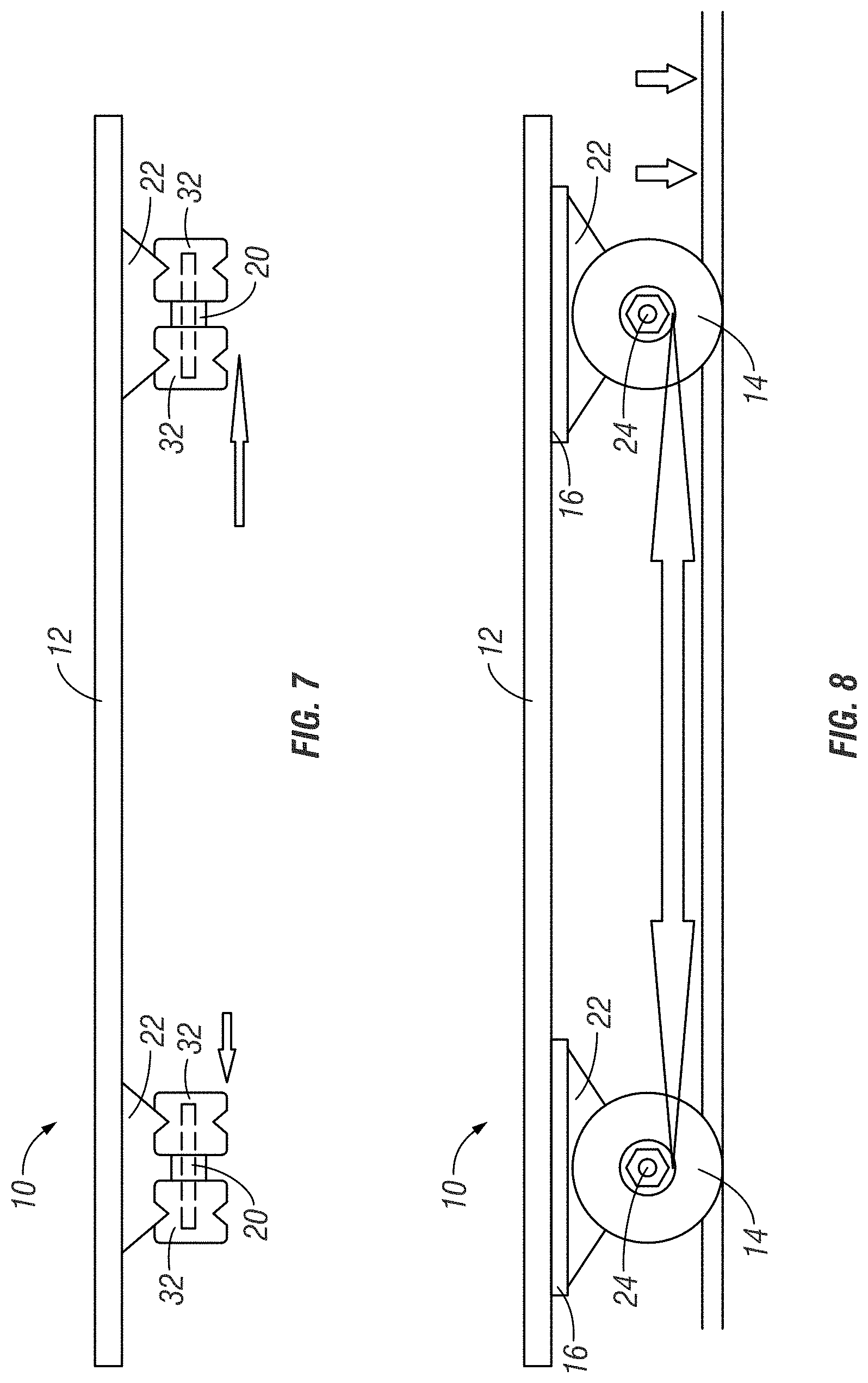
[0044] FIG. 7 shows a front elevation view of an alternative rolling or sliding inch worm style exercise apparatus having notched wheels that ride on an accompanying track, according to some aspects of the present disclosure.
[0045] FIG. 8 shows a side elevation view of an alternative rolling or sliding inch worm style exercise apparatus having notched wheels that ride on an accompanying track, the left and right side views being mirror images of one another, according to some aspects of the present disclosure.
[0046] FIG. 9 shows a bottom elevation view of a system including two platforms, the rolling or sliding inch worm style exercise apparatuses having a greased metal rod or pipe secured on the underside of both platforms, according to some aspects of the present disclosure.
[0047] FIG. 10 shows a front elevation view of a rear platform of the system of FIG. 9, the rear platform with a lubricated guide rod and back stop attached directly to the platform, the left and right side views being mirror images of one another, according to some aspects of the present disclosure.
[0048] FIG. 11 shows a side elevation view of a front platform of the system of FIG. 9, the front platform with a lubricated guide rod secured to the platform to allow for the guide rod to move within the guides, the left and right side views being mirror images of one another, according to some aspects of the present disclosure.
[0049] FIG. 12 shows a front elevation view of an alternative rolling or sliding inch worm style exercise apparatus having all-terrain wheels, according to some aspects of the present disclosure.
[0050] FIG. 13 shows a side elevation view of an alternative rolling or sliding inch worm style exercise apparatus having all-terrain wheels, the left and right side views being mirror images of one another, according to some aspects of the present disclosure.
[0051] FIG. 14 shows two platforms in an expanded position and FIG. 15 shows two platforms in a retracted position to illustrate the "inch worm" movement of the device.
[0052] Various embodiments of the present disclosure illustrate several ways in which the present invention may be practiced. These embodiments will be described in detail with reference to the drawings, wherein like reference numerals represent like parts throughout the several views. Reference to specific embodiments does not limit the scope of the present disclosure and the drawings represented herein are presented for exemplary purposes.
DETAILED DESCRIPTION OF THE INVENTION
[0053] The following definitions and introductory matters are provided to facilitate an understanding of the present invention. Unless defined otherwise, all technical and scientific terms used herein have the same meaning as commonly understood by one of ordinary skill in the art to which embodiments of the present invention pertain.
[0054] The terms "a," "an," and "the" include plural referents unless context clearly indicates otherwise. Similarly, the word "or" is intended to include "and" unless context clearly indicate otherwise. The word "or" means any one member of a particular list and also includes any combination of members of that list.
[0055] The terms "invention" or "present invention" as used herein are not intended to refer to any single embodiment of the particular invention but encompass all possible embodiments as described in the specification and the claims.
[0056] Terms such as first, second, vertical, horizontal, top, bottom, upper, lower, front, rear, end, sides, concave, convex, and the like, are referenced according to the views presented. These terms are used only for purposes of description and are not limiting unless these terms are expressly included in the claims. Orientation of an object or a combination of objects may change without departing from the scope of the invention.
[0057] The apparatuses, systems, and methods of the present invention may comprise, consist essentially of, or consist of the components of the present invention described herein. The term "consisting essentially of" means that the apparatuses, systems, and methods may include additional components or steps, but only if the additional components or steps do not materially alter the basic and novel characteristics of the claimed apparatuses, systems, and methods.
[0058] The following embodiments are described in sufficient detail to enable those skilled in the art to practice the invention however other embodiments may be utilized. Mechanical, procedural, and other changes may be made without departing from the spirit and scope of the invention. Accordingly, the scope of the invention is defined only by the appended claims, along with the full scope of equivalents to which such claims are entitled.
[0059] Referring now to the drawings, FIG. 1 shows a sliding exercise inch worm apparatus 10 viewed from the underside of a platform 12 comprising the apparatus 10. The platform 12 preferably comprises a rigid body with a rectangular shape however the surfaces of the platform 12 may take any known two-dimensional shape, such as ovals (including ellipses, circles, etc.), partial ellipses (including semicircles), stadiums, regular polygons (including triangles, rectangles, etc.), irregular polygons, cones, shapes of letters or numbers, curves and splines (i.e., a piecewise polynomial parametric curve, the shape of which depends on the values of the intervals it is made up of) extruded in two dimensions, or a combination of any of the preceding two-dimensional shapes.
[0060] The platform 12 includes several skateboard trucks preferably positioned in symmetric positions around the periphery of the platform 12 to more easily withstand stresses applied from the weight of people or objects placed on the top side of the platform. Each skateboard truck typically includes two wheels 14 secured to the platform 12 via an attaching member 16 and screws 18 on the top side of the platform 12, as is shown in FIG. 2. Padding may be placed over the screws 18 on the top side of the platform 12 to protect a user from scratching his or her elbows while exercising with the apparatus 10. The screws 18 may be replaced by or used in conjunction with nuts, bolts, pins, rivets, staples, clecos, washers, grommets, latches, clamps, lobster clasps, flanges, ties, adhesives, any other known fastening mechanisms, or any combination thereof may be used to facilitate securing the wheels 14 to the platform 12.
[0061] As shown in FIG. 3, the wheels 14 may be attached to one another via an axle assembly 20 which includes a rod or spindle (either fixed or rotating) passing through the center of the wheels 14. Furthermore, the wheels 14 may be integrally formed with or otherwise attached to a support member 22 which may allow for the swiveling of the wheels, thereby allowing the platform to be turned while a user exercises with the apparatus 10.
[0062] To exercise with the apparatus 10, a user may place his or her forearms/hands on the apparatus 10 and his or her feet/knees on the ground and push the apparatus 10 forward until the user is in the plank position (elbows directly beneath the user's shoulders, the user's body forming a straight line from the user's head to the user's feet). The user then "inches" or walks towards the apparatus 10 with his or her feet until his or her feet are close in proximity to the apparatus 10. The user may then repeat the process for a desired distance or until the user runs out of space. The user may also choose to place his or her feet/knees on the apparatus 10 and his or her forearms/hands on the ground and push the apparatus 10 forward until the apparatus 10 is close in proximity to the user's forearms/hands. The user then "inches" or walks away from the apparatus 10 with his or her forearms/hands until the user is in the plank position. The user may then repeat the process for a desired distance or until the user runs out of space. It is contemplated by the present disclosure that the user could move a "rearward" or "sideways" direction if the user were to position himself or herself looking away from the direction of travel. For example, the user may choose to place his or her feet/knees on the apparatus 10 and his or her forearms/hands on the ground and kick the apparatus 10 rearward until the user is in the plank position. The user then "inches" or walks towards the apparatus 10 with his or her forearms/hands until his or her forearms/hands are close in proximity to the apparatus 10. The user may then repeat the process for a desired distance or until the user runs out of space.
[0063] As shown in FIG. 4, the wheels 14 include a ratcheted or clutched one-way bearing 24 inside the wheels 14 which allows only for the platform 12 to move in a "forward" direction (e.g. in the direction indicated by the arrow in FIGS. 4, 6, 8, and 10-11). The ratcheted or clutched one-way bearings 24 do not allow the platform 12 to move in a rear direction while the user "inches" or walks towards/away the apparatus 10, increasing the stability of the apparatus 10 during use. The composition of or materials used to make the wheels 14 may affect how difficult it is to move the apparatus 10 in a forward direction and may be chosen to help increase or decrease a desired resistance which corresponds with the user's fitness level.
[0064] As shown in FIGS. 5 and 6, the apparatus 10 may include hand-controlled (via handles 26) break rods 28 with rubber or plastic stops 30. The break rod 28 can be held up by a user's hands and can be pushed down or dropped to stop forward motion if necessary. If a swiveling support member 22 is utilized, the handles 26 may be may comprise handlebars, a stick or pole acting as a lever arm, a steering wheel, or the like, and may be mechanically attached to the platform 12 to allow the platform 12 to be turned by an operator without having to twist the platform 12 itself. Furthermore, the handles 26 may comprise any material which assists the user in gripping the tool, such as knurling, specially shaped grooves, partially adhesive substances, any other materials known gripping mechanisms, or any combination thereof. This helps prevent the platform 12 from getting away from the user while exercising with the apparatus 10, thereby increasing the stability of the apparatus 10.
[0065] To further increase the stability of the apparatus 10, an alternative embodiment as shown in FIGS. 7-8 may be utilized. In such an embodiment, the wheels 14 are replaced with notched wheels 32 that ride on an accompanying track 34. The notched wheels 32 will ride the track in the same shape of the notch in the wheels 32 preserving directional control of the platform.
[0066] A second alternative embodiment for controlling the direction while exercising is contemplated in FIGS. 9-11. In such an embodiment, two platforms 12 are used. A greased or lubricated metal rod or pipe 36 is secured to the underside of both platforms 12 with ratcheted or clutched wheels 14 being included with at least one of the platforms 12. The rear platform includes a secured stop 38 allowing only the front platform to move in the forward direction through the guides 40 as the user's abdominal muscles provide energy to move the platforms 12 forward. A rod stop 44 may be permanently or removably attached to either or both of the first ends of the greased or lubricated metal rod or pipe 36 to prevent accidental disassembly of the apparatus during exercise. FIGS. 14-15 best illustrate the "inch-worm" movement of the platforms 12 while a user exercises.
[0067] An alternative configuration places larger all-terrain wheels 42 on the outside of the platforms with the same ratcheted or clutched trait, as shown in FIGS. 12-13. Having larger all-terrain wheels 42 on the outside of the platforms enable users on to take advantage of the same principles of engaging the user's abdominal muscles, while in a yard or football, soccer or baseball fields. The all-terrain wheels 42 may include tread which facilitates movement while in a yard or football, soccer or baseball fields.
[0068] The apparatus 10 may comprise various sensors. The sensors sense one or more characteristics of an object and can include, for example, accelerometers, position sensors, or pressure sensors among many others. The accelerometers can sense acceleration of an object in a variety of directions (e.g., an x-direction, a y-direction, etc.). The position sensors can sense the position of one or more components of an object. For example, the position sensors can sense the position of an object relative to another fixed object such as a wall. Pressure sensors can sense the pressure exerted on the apparatus 10. Fewer or more sensors can be provided as desired. For example, a rotational sensor can be used to detect speed(s) of object(s), motion or distance sensors can be used to detect the distance an object has traveled, one or more timers can be used for detecting a length of time an object has been used and/or the length of time any component has been used, and temperature sensors can be used to detect the temperature of an object or fluid.
[0069] The sensors of the apparatus 10 can output any sensed characteristics to a display such that the display can show conditions or data associated with the main device in real-time or substantially real-time. More specifically, the display could be a liquid crystal display ("LCD"), a light-emitting diode ("LED") display, an organic LED ("OLED") display, an electroluminescent display ("ELD"), a surface-conduction electron emitter display ("SED"), a field-emission display ("FED"), a thin-film transistor ("TFT") LCD, a bistable cholesteric reflective display (i.e., e-paper), etc. According to some additional aspects of the disclosure, the display may be configured with a user interface controlled by a microcontroller capable of interpreting user input(s) from input devices such as a touch-screen, knobs, dials, switches, buttons, etc.
[0070] Artificial lighting or light fixtures may be positioned on the apparatus or system to achieve a practical or aesthetic affect consistent with the objects of the present disclosure, such as illuminating an area for visibility at night or for warning others about a potential collision. A nonlimiting example of artificial lighting is small light emitting diode ("LED") lamps. Such light fixtures would require a power source, such as a battery.
[0071] From the foregoing, it can be seen that the present invention accomplishes at least all of the stated objectives.
LIST OF REFERENCE NUMERALS
[0072] The following list of reference numerals is provided to facilitate an understanding and examination of the present disclosure and is not exhaustive. Provided it is possible to do so, elements identified by a numeral may be replaced or used in combination with any elements identified by a separate numeral. Additionally, numerals are not limited to the descriptors provided herein and include equivalent structures and other objects possessing the same function. [0073] 10 rolling or sliding inch worm style exercise apparatus [0074] 12 platform, including an underside and top side [0075] 14 wheel [0076] 16 attaching member [0077] 18 screw or other fastening mechanism [0078] 20 axle assembly [0079] 22 support member [0080] 24 ratcheted or clutched one-way bearing [0081] 26 handle [0082] 28 actuatable break rod [0083] 30 rubber/plastic break [0084] 32 notched wheel [0085] 34 track [0086] 36 greased rod or pipe [0087] 38 secured stop(s) [0088] 40 guides [0089] 42 all-terrain wheels [0090] 44 rod stop(s)
[0091] The present disclosure is not to be limited to the particular embodiments described herein. The following claims set forth a number of the embodiments of the present disclosure with greater particularity.
* * * * *
D00000
D00001
D00002
D00003
D00004
D00005
D00006
D00007
D00008
D00009
XML
uspto.report is an independent third-party trademark research tool that is not affiliated, endorsed, or sponsored by the United States Patent and Trademark Office (USPTO) or any other governmental organization. The information provided by uspto.report is based on publicly available data at the time of writing and is intended for informational purposes only.
While we strive to provide accurate and up-to-date information, we do not guarantee the accuracy, completeness, reliability, or suitability of the information displayed on this site. The use of this site is at your own risk. Any reliance you place on such information is therefore strictly at your own risk.
All official trademark data, including owner information, should be verified by visiting the official USPTO website at www.uspto.gov. This site is not intended to replace professional legal advice and should not be used as a substitute for consulting with a legal professional who is knowledgeable about trademark law.