Drawer Slide Assembly
Wang; Guanwen ; et al.
U.S. patent application number 16/630312 was filed with the patent office on 2020-07-09 for drawer slide assembly. The applicant listed for this patent is Plant IP Pty Ltd. Invention is credited to Gary Raymond Plant, Ronald Rae, Guanwen Wang.
| Application Number | 20200214445 16/630312 |
| Document ID | / |
| Family ID | 65000952 |
| Filed Date | 2020-07-09 |


View All Diagrams
| United States Patent Application | 20200214445 |
| Kind Code | A1 |
| Wang; Guanwen ; et al. | July 9, 2020 |
DRAWER SLIDE ASSEMBLY
Abstract
A slide assembly 30 is provided for slidably mounting a drawer 200 within a carcass 101. The slide assembly includes a runner bar 16 and a slide limiter. The runner bar 30 has a first slidable connection 36,48 for slidably mounting the drawer 200 for sliding movement relative to the runner bar 30 between retracted and extended configurations. The runner bar 30 also has a second slidable connection 42, 50 for slidably mounting the runner bar 30 for sliding movement relative to the carcass 101 between retracted and extended configurations. The slide limiter includes stops 72, 80, 82, 372, 380, 382 for limiting the relative extension of the drawer 200 and the runner bar 46, and the runner bar 46 and the carcass 101. The stops 72, 80, 82, 372, 380, 382 are discrete from the first and second slidable connections 36, 48, 42, 50.
| Inventors: | Wang; Guanwen; (Chengdu, CN) ; Plant; Gary Raymond; (Cairns, AU) ; Rae; Ronald; (Pacific Pines, AU) | ||||||||||
| Applicant: |
|
||||||||||
|---|---|---|---|---|---|---|---|---|---|---|---|
| Family ID: | 65000952 | ||||||||||
| Appl. No.: | 16/630312 | ||||||||||
| Filed: | July 13, 2018 | ||||||||||
| PCT Filed: | July 13, 2018 | ||||||||||
| PCT NO: | PCT/AU2018/050730 | ||||||||||
| 371 Date: | January 10, 2020 |
| Current U.S. Class: | 1/1 |
| Current CPC Class: | A47B 2210/0043 20130101; A47B 88/437 20170101; A47B 88/49 20170101; A47B 88/57 20170101; A47B 88/473 20170101; A47B 88/493 20170101; A47B 2210/0032 20130101; A47B 2210/0059 20130101; A47B 2210/02 20130101 |
| International Class: | A47B 88/57 20060101 A47B088/57; A47B 88/493 20060101 A47B088/493 |
Foreign Application Data
| Date | Code | Application Number |
|---|---|---|
| Jul 13, 2017 | CN | 201710569788.1 |
| Jul 13, 2017 | CN | 201720848326.9 |
| Jul 13, 2017 | CN | 201720848363.X |
| Aug 17, 2017 | AU | 2017903315 |
Claims
1. A slide assembly for slidably mounting a drawer within a carcass, the slide assembly including: a runner bar having a first slidable connection for slidably mounting the drawer for sliding movement relative to the runner bar between retracted and extended configurations, the runner bar having a second slidable connection for slidably mounting the runner bar for sliding movement relative to the carcass between retracted and extended configurations; and a slide limiter including stops for limiting the relative extension of the drawer and the runner bar, and the runner bar and the carcass, wherein the stops are discrete from the first and second slidable connections.
2. The slide assembly as claimed in claim 1 wherein the stops of the slide limiter include: a first set of inter-engageable stops including a first runner stop disposed on the runner bar and a drawer stop for fixedly mounting on the drawer; and a second set of inter-engagable stops including a second runner stop disposed on the runner bar and a body stop for fixedly mounting on the carcass.
3. The slide assembly as claimed in claim 2 wherein the drawer stop and the body stop are movable relative to the runner bar along respective dedicated pathways in the runner bar, discrete from any tracks provided for the slidable connections.
4. The slide assembly as claimed in claim 3 wherein the dedicated pathways are in the form of channels in the runner bar on opposite sides of the runner bar.
5. The slide assembly as claimed in claim 3 wherein the runner bar is arranged with the first slidable connection and the second slidable connection, one above the other with a bridging portion therebetween and the dedicated pathways are disposed on either side of the bridging portion.
6. The slide assembly as claimed in claim 1 wherein the runner stops are fitted at each end of the runner bar to close the channels.
7. The slide assembly as claimed in claim 2 wherein the stops of the first set are removably interconnectable and the stops of the second set are removably interconnectable.
8. The slide assembly as claimed in claim 1 wherein the runner bar has tracks to accommodate drawer-mounted wheels or rollers and carcass-mounted wheels or rollers.
9. The slide assembly as claimed in claim 4 wherein the runner bar has a first track above a second track.
10. The slide assembly as claimed in claim 9 wherein the two tracks are each open to a respective side of the runner bar to define an S-shaped cross-section.
11. The slide assembly as claimed in claim 9 wherein the slide limiter is disposed in the channels between the two tracks.
12. The slide assembly as claimed in claim 9 wherein a bridging portion is provided between the two tracks with the channels for the drawer stop and the body stop respectively disposed on each side of the bridging portion.
13. The slide assembly as claimed in claim 2, further including an outer drawer plate for mounting on the outside of a drawer side panel, whereby drawer wheels and the drawer stop are mounted on the outer drawer plate.
14. The slide assembly as claimed in claim 13 wherein an inner drawer plate is provided for mounting on the inside of the drawer side panel to provide additional support.
15. The slide assembly as claimed in claim 2, further including a first body plate for mounting on one side of a carcass side panel wherein body wheels and the body stop are provided on the first body plate.
16. The slide assembly as claimed in claim 15 wherein a second body plate is provided for mounting on the other side of the carcass side panel.
17. A slide assembly for slidably mounting a drawer within a carcass, the slide assembly including: a first runner bar having a first slidable connection for slidably mounting the drawer for sliding movement relative to the first runner bar between retracted and extended configurations, the first runner bar having a second slidable connection for slidably mounting the first runner bar for sliding movement relative to the carcass between retracted and extended configurations; a first slide limiter including stops for limiting the relative extension of the drawer and the first runner bar, and the first runner bar and the carcass, wherein the stops are discrete from the first and second slidable connections; a second runner bar having a third slidable connection for slidably mounting the drawer for sliding movement relative to the second runner bar between retracted and extended configurations, the second runner bar having a fourth slidable connection for slidably mounting the second runner bar for sliding movement relative to the carcass between retracted and extended configurations; a second slide limiter including further stops for limiting the relative extension of the drawer and the second runner bar, and the second runner bar and the carcass, wherein the further stops are discrete from the third and fourth slidable connections.
18. The slide assembly as claimed in claim 17 wherein the first and second runner bars are connected by a joining bar.
19. A drawer assembly including a drawer slidably mounted within a carcass using a slide assembly as claimed in claim 1.
Description
FIELD OF THE INVENTION
[0001] The present invention relates to a slide assembly. In particular, although not exclusively, the invention relates to a drawer slide assembly for slidably mounting a drawer within a cabinet body or carcass. The present invention has particular application to an ancillary storage unit for a vehicle. However, the invention may also have application to other kinds of cabinets and furniture systems where a drawer slides relative to the cabinet body. The invention may also have application beyond a drawer and could have application to pull out desks, trundle beds and other furniture applications. Furthermore, the invention could also have application beyond furniture and storage units.
BACKGROUND OF THE INVENTION
[0002] Ancillary storage units, particularly for use in vehicles are known. Generally, these are used for storage of tools and have slidable drawers which may be accessed by the user through an opening in the vehicle such as the back or side of a utility vehicle or the boot of a car. When used in recreational vehicles, it is sometimes desirable to use these drawers to store refrigeration units. Accordingly, it is particularly useful if the drawer can pull out from the cabinet body as far as possible in order to increase the access opening into the drawer, particularly when a refrigeration unit is stored within the drawer. For this purpose, it is known to use a floating runner bar to which the drawer is slidably mounted, the runner bar also being slidably mounted relative to the cabinet body. This permits the drawer to extend beyond what would normally be permitted if the drawer was directly slidably mounted to the cabinet body.
[0003] WO 2016/090406 discloses one particular storage cabinet with a drawer, cabinet body and a floating runner bar. The arrangement in D1 relies on drawer-mounted wheels rolling in a track on the runner bar and cabinet-mounted wheels which roll within another track on the runner bar. The runner bar has two plugs which are placed at either end which incorporate respective stopping mechanisms. When the drawer is opened sufficiently from the cabinet body, one of the drawer wheels abuts against the forward stopping mechanism of the runner bar. Further opening of the drawer causes extension of the runner bar out of the cabinet body until the rearward stopping mechanism abuts one of the cabinet wheels. The wheels which engage with the stopping mechanisms are referred to as "stopper wheels" which are part of the set of drawer mounted wheels and body-mounted wheels. Thus, repeated impact between the stopper wheels and the stopping mechanisms could damage the wheels and hinder their rolling function.
[0004] It is an object of the present invention to provide a slide assembly which addresses the above mentioned disadvantage or at least provides the public with a useful choice over known slide assemblies.
SUMMARY OF THE INVENTION
[0005] In accordance with an aspect of the present invention, there is provided a slide assembly for slidably mounting a drawer within a carcass, the slide assembly including:
[0006] a runner bar having a first slidable connection for slidably mounting the drawer for sliding movement relative to the runner bar between retracted and extended configurations, the runner bar having a second slidable connection for slidably mounting the runner bar for sliding movement relative to the carcass between retracted and extended configurations; and
[0007] a slide limiter including stops for limiting the relative extension of the drawer and the runner bar, and the runner bar and the carcass, wherein the stops are discrete from the first and second slidable connections.
[0008] Thus, preferably the stops do not perform any functioning role of the slidable connections. The function of the slide limiter is therefore preferably independent of the slidable connections. The stops may therefore be dedicated to the function of the slide limiter, not forming a dual role as part of the slidable connections i.e. wheels of the slidable connection do not function as stops to limit the sliding extension of the drawer or the runner bar. Thus, the stops are preferably non-rotatable.
[0009] In a preferred form of the invention, the slide limiter includes a first set of inter-engageable stops including a first runner stop disposed on the runner bar and a drawer stop for fixedly mounting on the drawer. The slide limiter may also include a second set of inter-engagable stops including a second runner stop disposed on the runner bar and a body stop for fixedly mounting on the carcass. In this preferred form of the invention, when the drawer is fully extended from the carcass, the drawer stop engages with the first runner stop and the second runner stop engages with the body stop to define the limit of full extension of the drawer.
[0010] In a preferred form of the invention, the drawer stop and the body stop move relative to the runner bar along respective dedicated pathways in the runner bar. The dedicated pathways are suitably discrete from any tracks provided for the slidable connection. The dedicated pathways may be in the form of channels in the runner bar. The dedicated pathways may be on opposite sides of the runner bar. Preferably, the runner bar is arranged with the first slidable connection and the second slidable connection, one above the other with a bridging portion therebetween and the dedicated pathways are disposed on either side of the bridging portion.
[0011] The runner stops may be integrally moulded with the runner bar. Alternatively, the runner stops may be in the form of a moulded fitting. The moulded runner stops may fit onto an extruded runner bar. The runner stops may be fitted at each end of the runner bar to close the channels.
[0012] The inter-engagement between the stops of the slide limiter may be by abutment only. However, in a more preferred form of the invention, the stops of the slide limiter may be removably interconnectable to retain the drawer in a predetermined position such as the fully extended position. More specifically, the first set of stops may be removably interconnectable, for example, nestable profiles such as tongue and groove. Likewise, the second set of stops may be removably interconnectable.
[0013] The slide connection may be in the form of slidably engageable surfaces. Alternatively, the slide connection may be in the form of a rolling part and a track. For example, the rolling part may comprise wheels, rollers, ball bearings which are moveable along a track.
[0014] Preferably the runner bar has tracks to accommodate the drawer-mounted wheels or rollers and carcass-mounted wheels or rollers. Alternatively, the wheels or rollers may be mounted on the runner bar for running along respective tracks in the drawer and carcass.
[0015] Preferably, the runner bar has a first track above a second track. The two tracks may be open to a respective side of the runner bar. Thus, the runner bar may have a S-shaped cross section. Preferably, the slide limiter is disposed in the channels between the two tracks. In a most preferred form of the invention, the bridging portion mentioned above may be provided between the two tracks with the channels for the drawer stop and the body stop disposed on each side of the bridging portion.
[0016] The slide assembly may also include an outer drawer plate for mounting on the outside of the drawer side panel. The drawer wheels and the drawer stop may be mounted on the outer drawer plate. Additionally, an inner drawer plate may be provided for mounting on the inside of the drawer side panel to provide additional support.
[0017] Additionally, the slide assembly may include a first body plate for mounting on one side of the carcass side panel. The body wheels and the body stop may be provided on the first body plate. A second body plate may also be provided for mounting on the other side of the carcass side panel.
[0018] The drawer plates and the body plates may be integrally formed with the drawer side panel and the carcass side panel respectively.
[0019] The slide assembly may include a first such runner bar and first such slide limiter for mounting on a first side of the drawer and a second such runner bar and a second such slide limiter for mounting on the second side of the drawer. The first and second runner bars may be connected by a joining bar.
[0020] In accordance with a second aspect of the present invention, there is provided a drawer assembly including a drawer slidably mounted within a carcass using a slide assembly as defined above in connection with the first aspect of the invention.
[0021] Any of the features described above in connection with the first aspect of the invention may be applied to the second aspect of the invention.
[0022] It will be understood that the invention disclosed and defined in this specification extends to all alternative combinations of two or more of the individual features mentioned or evident from the text or drawings. All of these different combinations constitute various alternative aspects of the invention.
BRIEF DESCRIPTION OF THE DRAWINGS
[0023] In order that the invention may be more fully understood, one embodiment will now be described, by way of example, with reference to the figures in which:
[0024] FIG. 1 is a perspective view of a fully assembled storage unit in accordance with a first preferred embodiment of the present invention;
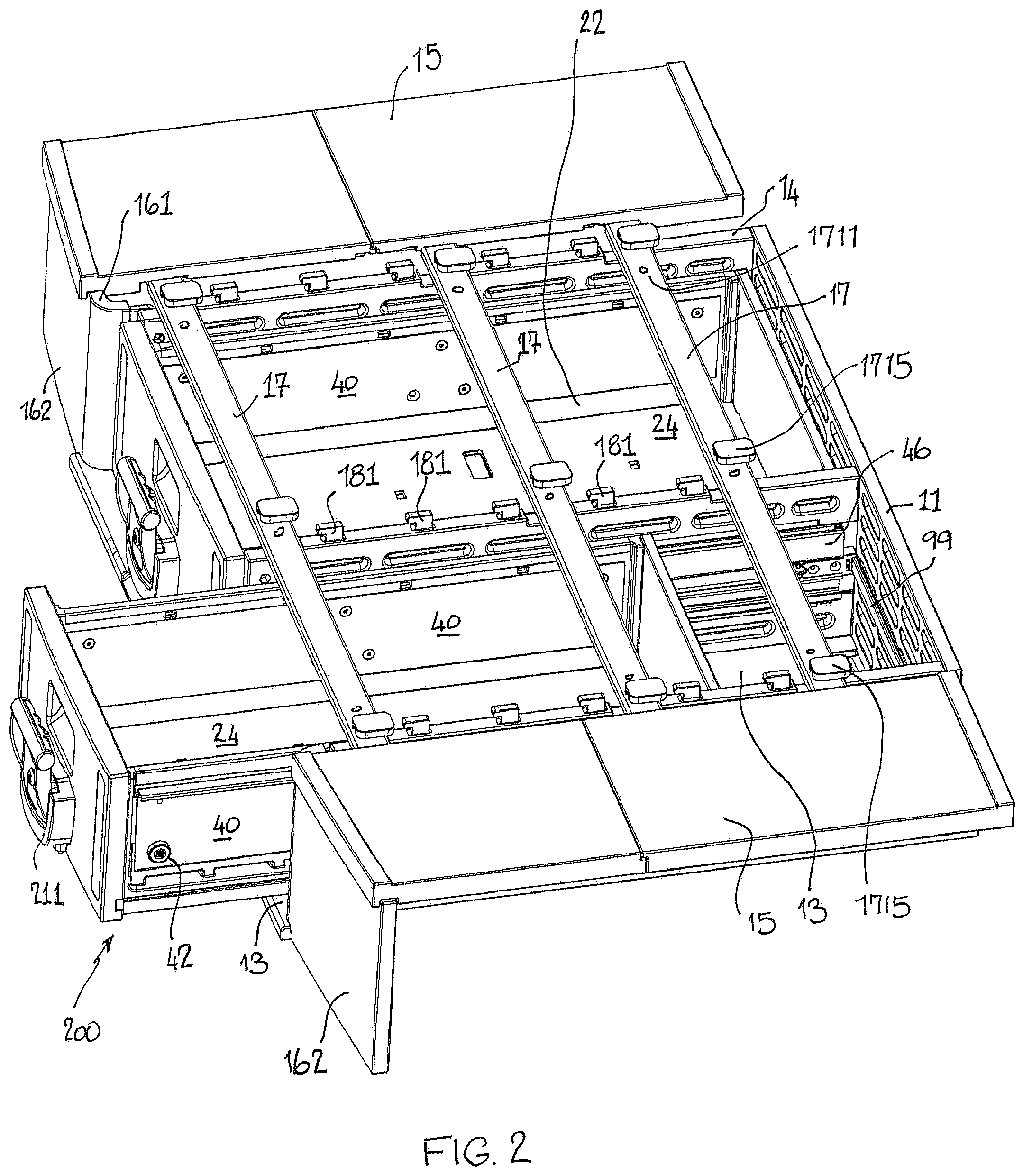
[0025] FIG. 2 is a perspective view of the storage unit of FIG. 1, except with the top panel removed;
[0026] FIG. 3 is a perspective view of the storage unit shown in FIGS. 1 and 2, except showing various parts removed for clarity including the top panel, one of the extension panels and the front panel of one of the drawers;
[0027] FIG. 4 is a perspective view substantially from the front of the storage unit shown in FIG. 1, except with various parts removed including one of the extension panels, the front panel of one of the drawers and the adjacent side panels of the drawer and carcass at A;
[0028] FIG. 5 is a perspective view similar to FIG. 4;
[0029] FIG. 6 is a detailed perspective view of the drawer slide assembly as per A in FIG. 4, the side panels of the drawer and the carcass being removed for clarity;
[0030] FIG. 7 is a detailed perspective view of the drawer slide assembly as per B in FIG. 5;
[0031] FIG. 8 illustrates the section of a runner bar used in the drawer slide assembly of FIGS. 6 and 7;
[0032] FIG. 9 is a partial view of the drawer slide assembly of FIGS. 6 and 7, except with the drawer plates for the carcass side panel being removed for clarity;
[0033] FIG. 10 is a perspective view similar to FIG. 9, except additionally showing the runner bar removed for clarity;
[0034] FIG. 11 is an exploded perspective view of a drawer and a carcass side panel showing the drawer slide assembly mounted on the carcass side panel;
[0035] FIG. 12 is an exploded perspective view similar to FIG. 11, except showing the runner bar removed for clarity;
[0036] FIG. 13 is a perspective view of a spring catch used to retain the drawer in the open and closed configuration;
[0037] FIG. 14 is a perspective view of a storage unit similar to FIG. 3 except according to a second preferred embodiment which is similar in many respects to the first preferred embodiment;
[0038] FIG. 15 is a perspective view of a runner assembly incorporated into the storage unit of the second preferred embodiment, the runner assembly being shown with the side plates for the carcass side panel having been removed for clarity;
[0039] FIG. 16 is a perspective view from the rear of a drawer of the storage unit shown in FIG. 14;
[0040] FIG. 17 is a perspective view from the rear of a side panel of the carcass assembled with the drawer slide assembly;
[0041] FIG. 18 is an exploded view showing the drawer of FIG. 16, except with the rear panel of the drawer removed for clarity, together with a side panel of the carcass, showing portions of the drawer slide assembly, similar to FIG. 17, except with the runner bars removed for clarity;
[0042] FIG. 19 is an assembled view of the drawer of FIG. 18, together with the opposite side panel of the carcass, showing the runner bar in position, with the near side panel of the carcass removed for clarity, the drawer being shown in the fully closed configuration;
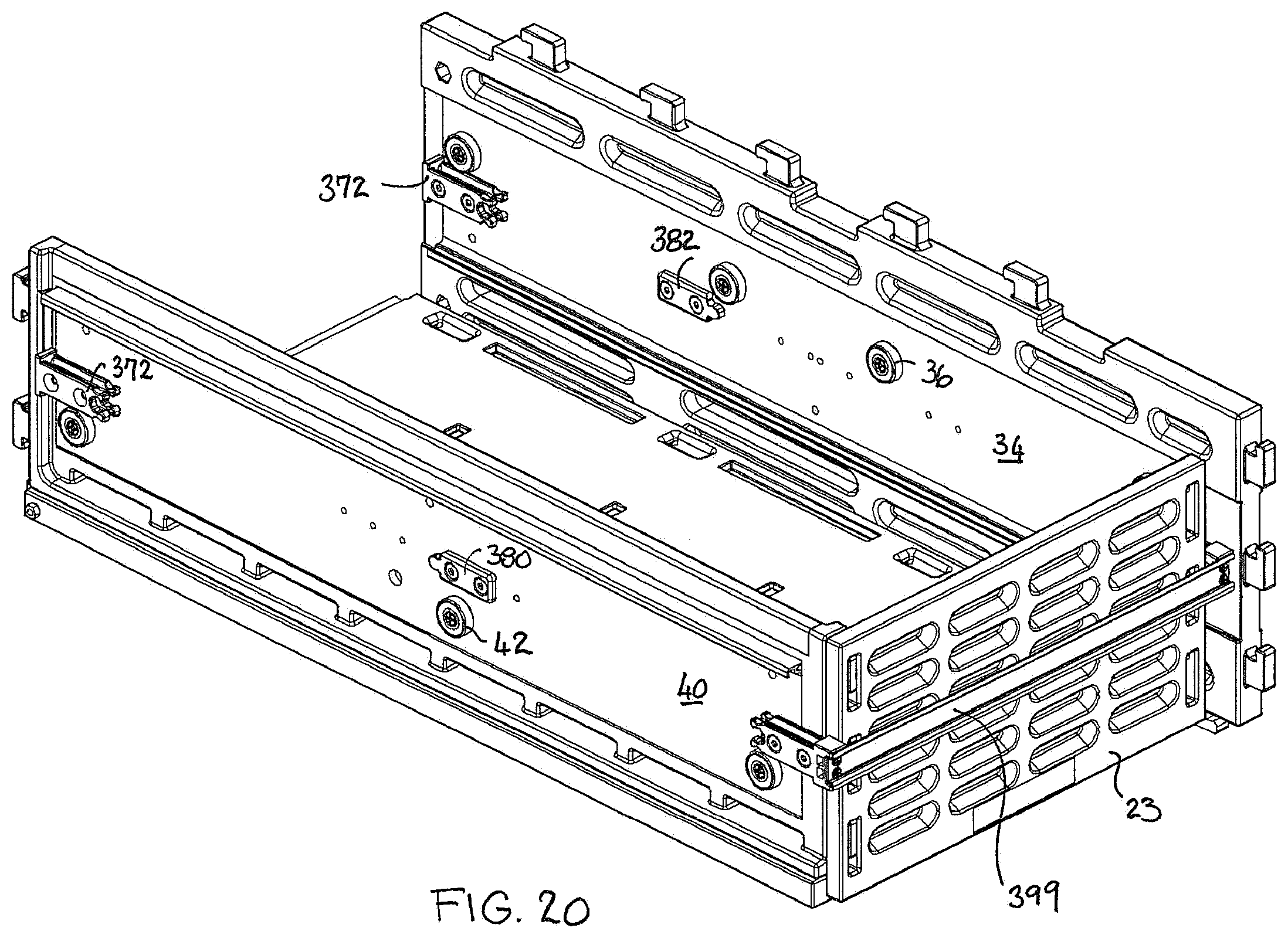
[0043] FIG. 20 is a perspective view similar to FIG. 19, except showing the near runner bar and the far side panel of the drawer removed for clarity;
[0044] FIG. 21 is a perspective view of the drawer of FIG. 19, except shown in the fully extended configuration, the far runner bar removed for clarity;
[0045] FIG. 22 is a view similar to FIG. 21 with the drawer fully extended, except with both of the runner bars removed for clarity;
[0046] FIG. 23 is a perspective view of the drawer except shown without front and rear panels, shown with the drawer fully received within the carcass.
DETAILED DESCRIPTION OF THE EMBODIMENTS
First Embodiment
[0047] The figures show a multipurpose vehicle-mounted storage unit 10 which is made up of flat-packable panels which are substantially planar or plate-like. Many features of the unit 10 are similar to the unit described and shown in our earlier PCT applications WO2018/014079 and WO2018/014080, details of which are incorporated herein by reference.
[0048] The panels may be shipped to the end user in a flat-pack for do-it-yourself assembly by the end user. The panels and the assembly features provided thereon, also lend themselves to being de-constructed as desired by the end-user for lower volume storage. The panels make up a carcass 101 (best shown in FIG. 3) to form compartments to accommodate a number of drawers 200. The drawers 200 are also constructed from flat-packable panels.
[0049] As shown in FIGS. 1 to 5, the storage unit 10 has a carcass 101 comprising a rear panel 11, a horizontally arranged top panel 12 (see FIG. 1) and bottom panel 13, and several upright divider panels 14 uprightly placed between the top panel 12 and bottom panel 13. The panels 11, 12, 13 and 14 are all fabricated using the construction technique of blow-moulding of plastics material e.g. polypropylene to produce hollow panels.
[0050] The bottom panel 13, top panel 12, and rear panel 11 are connected to the divider panels 14 with mortise-tenon joints, thus forming two side-by-side storage compartments used for placing drawers 200 as shown in FIGS. 1 to 3. When the unit 10 is installed, these compartments open towards the same direction as the opening in the vehicle (not shown).
[0051] Support Beams
[0052] As shown in FIG. 2, three continuous support beams 17 extend across the upper edges of the divider panels 14 and received in complementary recesses provided on the underside of the top panel 12. The top panel 12 is fixed to the beams 17 with fastenings (not shown).
[0053] Each fastening passes through the top panel 12. There are 3 rows of fasteners spaced across the top panel 12. The central row of fasteners are fixed in fastening screw holes 17 which are threaded holes provided in the beams 17.
[0054] As shown in FIGS. 1 and 2, a dust cap 1715 is placed on the top of the fastener. The dust cap 1715 prevents dust and dirt from entering into the fastener and the fastening screw hole 1711 and thus protects them from rust and other damage to prolong their service life.
[0055] The support beams 17 are each comprised of a central flattened aluminium tube 1710 of approximately rectangular cross-section which is able to receive extendible and retractable extension pieces (not shown). Each extension piece is provided with a series of spaced adjustment holes (not shown) which are threaded and allow adjustment of the extension/retraction of the extension pieces. The outer rows of fasteners seat into aligned holes in the support bars and the extension pieces to allow for adjustment.
[0056] The telescopic beams 17 permit the overall width of the unit 10 to be reduced for easy removal from the rear of the vehicle. Generally the width of the opening of a vehicle such as the boot opening, hatch or tailgate is less than the width inside the vehicle so this feature allows easy removal of the unit 10 from the vehicle.
[0057] Further details of the support beams are shown and described in the above mentioned PCT applications which are incorporated herein by reference.
[0058] Sundries Compartments
[0059] As shown in FIGS. 1-3, extension panels 15 that are flush with the top panel 12 are fixed to the beams 17 at the ends of the beams 17/extension pieces. On each side of the carcass 101, the extension panel 15, the inner wall of the vehicle body (not shown) and the adjacent divider panel 14 form a sundries compartment which is convenient for holding tools and articles. The extension panel 15 increases the flat extent of the top surface of the unit and makes it feasible to place luggage and other objects on top of the storage unit.
[0060] As shown in FIGS. 1-3, at the front of each sundries compartment, front panels 16 are fixed to the divider panels 14 on both sides of the unit 10. The upper edge of the front panel 16 is fixed to the top panel 12 and extension panel 15 through a grooved connection (see FIG. 2), and the lower edge is fixed to the bottom panel 13 through a grooved connection.
[0061] The front panel 16 is composed of a curved segment 161 and a flat baffling segment 162, which are unitarily moulded in one piece. The curved segment 161 is fixed to the outer side of the divider panel 14, and installed into two complementary arc-shaped grooves on the undersurface of the top panel 12 and the top surface of the bottom panel 13, which are consistent with the curved segment 161 in shape.
[0062] The upper edge of the baffling segment 162 is fixed to the underside of the extension panel 15 through a grooved connection. There is a straight groove on the underside of the extension panel 15, which matches with the upper edge of the baffling segment 162, and the upper edge of the baffling segment 162 is embedded in the straight groove 150.
[0063] The curved segment 161 is convenient for fixing the front panel 16 to the divider panel 14, and the baffling segment 162 keeps the front of the unit flat. The front panel 16 can prevent articles in the sundries compartment from falling out and further improve the effectiveness of space partitioning.
[0064] The sundries compartment can be used for storing car repair tools. Further details of the sundries compartments are shown and described in the above-mentioned PCT applications which are incorporated herein by reference.
[0065] Mortice-Tenon Joints
[0066] As shown in FIGS. 2 and 3, the upper edges, lower edges, and rear edges of all the divider panels 14 are provided with aligned tenons 181, and the bottom panel 13, top panel 12, and rear panel 11 are all provided with mortises (not shown) at the corresponding positions. The tenons 181 mate with the mortises to form a roughly cuboid structure of the carcass 101. It is very easy to assemble the panels with mortise-tenon joints. When not in use, the carcass 101 can be disassembled for easy storage, thus giving users more autonomy and flexibility.
[0067] The mortises are all of the same form and the tenons 181 are also all of the same form throughout the unit 10. The tenons 181 are integrally moulded with the associated divider panel 14. Likewise, the material surrounding the mortices i.e. the mortise surrounds, are integrally moulded with the associated panel.
[0068] Each tenon 181 is formed as a projection extending from the panel, in line with the general plane of the divider panel 14. The tenon 181 has a hook profile.
[0069] The mortice surround defines a slotted mortice hole which is complementary to and cooperates with the hook profile of the tenon 181. The tenons 181 engage with respective mortice surrounds with a snap engagement. The tenons 181 are pushed into the respective surrounds and then with a relative sliding movement, the tenons are pushed into a home position, effecting the snap engagement. Further detail of the mortice and tenon joins are described in the foregoing PCT applications, details of which are incorporated herein by reference.
[0070] When assembling the carcass 101, the user should first assemble all the divider panels 14 on the bottom panel 13 by inserting the tenons 181 into the corresponding mortises of the bottom panel, and then longitudinally pushing the divider panels 14 until each hook profile is seated in its home position. Thus, the bottom panel 13 remains stationary while each divider panel 14 is pushed to seat the tenons 181 in the home position in the mortice. The rear panel 11 is then assembled with the divider panels with the tenons 181 at the rear edges of the divider panels received in the mortices of the rear panel 11. The rear panel is pushed down to lock the tenons in place--and a longitudinal rib on the bottom edge of the rear panel seats in a groove in the upper face of the bottom panel.
[0071] The support beams 17 and extension pieces are positioned as explained above.
[0072] The top panel 12 is overlaid onto the divider panels 14 to line up the tenons on the divider panels 14 with the mortices in the top panel 12. The tenons 181 must be all received in the top panel 12 before the top panel 12 is pushed rearwardly so that the tenons 181 in the divider panels 14 seat in the home position in the mortices in the top panel 12.
[0073] This structure is very simple to assemble, easy to operate, and rigid in final form. Dismantling is possible if desired but requires individual prising apart of each tenon/mortice pair with a suitable pronged tool.
[0074] Seals (not shown) may be provided to insert into the mortice holes from above the top panel 12 to seal the mortice holes and prevent entry of dirt and other debris.
[0075] In this embodiment, there are several sunken grooves 141 (see FIG. 3) on the upper edges of the divider panels 14, and the support beams 17 are placed in the grooves 141 so as to avoid the situation that the beams 17 protrude over the upper edge of the divider panel 14, which would otherwise impair the tenon-mortise joint between the divider panel 14 and the top panel 12.
[0076] Mounting in Vehicle
[0077] The rear edge of the bottom panel 13 may have margin (not shown) of reduced thickness.
[0078] To position the storage unit in a vehicle, reduced thickness margin of bottom panel 13 is pushed with a firm fit into a channel portion of a matching hollow metal section (not shown) that is fixed across the vehicle floor at the rear edge of bottom panel 13. If desired, the unit is fastened into place by suitable clamps or other releasable fasteners at the sides of outer divider panels 14 (not shown).
[0079] Drawers
[0080] As shown in FIGS. 1 to 3, the drawers 200 of the vehicle-mounted storage unit proposed in this embodiment may be used for storing articles. Additionally, the drawer 200 may be utilised for placing a vehicle-mounted refrigerator 203 or insulated unit. In this particular embodiment, there is a large drawer 201 for accommodating a refrigerator 203 and a smaller drawer 202 for other articles. The large drawer 201 and the smaller drawer 202 are of substantially the same construction.
[0081] As shown in FIGS. 11 and 12, the drawer 200 consists of a bottom panel 24, a handle-bearing panel 21 in the front, a rear panel 23 at the back, and two upright panels 22 on each side.
[0082] The handle-bearing panel 21 is provided with a handle 211 (FIG. 2) which is lockable.
[0083] The rear panel 23 may be provided with ventilation holes 230, designed for promoting heat transfer of the refrigerator 203.
[0084] The front edge of the upright panel 22 is provided with first tenons (not shown), and the back edge provided with second tenons 224 and the lower edge is provided with third tenons (not shown). There are first mortises at the front of the handle-bearing panel 21, three on each side, which match with the first tenons. The handle-bearing panel 21 is connected to the upright panels 22 through mortise-tenon joints. Front plates 213 (see FIG. 1) disguise these mortice-tenon joints and depending on the selected material, can reduce vibration in the front mortice-tenon joints. An insulative or sound absorbent material such as cotton may reduce vibration and extend service life.
[0085] There are second mortises (not shown) on the rear panel 23 which match with the second tenons 224 (FIG. 12) on the upright panel 22. There are third mortices (not shown) on the bottom panel 24 which match with the third tenons (not shown) of the upright panel 22. The bottom panel 24 and the rear panel 23 are thus connected to the upright panels 22 through mortise-tenon joints.
[0086] The configuration of the tenon projections and the mortice holes and surrounds is the same for the drawers as that described above for the carcass 101. The resulting mortice-tenon joints are therefore the same.
[0087] Structure of Panels
[0088] The panels of the drawers 200 and carcass 101 are in a unitary hollow structural form of a panel constructed from plastic material e.g. polypropylene, using blow-moulding so the panel is of low weight and easy to manufacture. The rear panel 23 of the large drawer 201 has an arrayed recess structure which is similarly applied to all of the panels used in the storage unit 10. The panel 23 may have removable pieces 230 (FIG. 11) in the recesses 237 to provide ventilation openings when the large drawer 201 is used to house a refrigerator 203. These removable pieces 230 may be selectively removed by the end user. The feature of the removable ventilation pieces 230 may also be applied to the rear panel 11 of the carcass 101. The divider panels 14 in the carcass 101 may also have removable pieces within at least some of the recesses.
[0089] The panel 23 has a cavity (not shown) enclosed by two spaced walls which reduces the overall weight of the panel 23. The outer surface of the first wall 231 is provided with an array of recesses 237 that are arranged at regular intervals transversely and longitudinally and sunken into the cavity 233. Each recess 237 is of rectangular or slotted shape with generally rounded ends as shown in FIG. 11.
[0090] The inner surface of the first wall in the region of the recess 237 may be closely spaced or connected to the second wall, or there a clearance may be provided between them. The cavity with the panel 23 is thus punctuated by the recesses 237. Both the first wall and the second wall may have an array of recesses 237 with the recesses in each wall meeting to define a "waffle" structure.
[0091] Drawer Slide Assembly
[0092] FIGS. 6 and 7 illustrate the components of the drawer slide assembly 30. The drawer slide assembly 30 is disposed to permit sliding movement between the drawer 200 and the carcass 101. In the first embodiment, the drawer slide assembly 30 is made up of two sub-assemblies disposed on opposite sides of the drawer. In the second embodiment, the two sub-assemblies are linked by a joining bar 399 (FIG. 23). The sub-assemblies each provide a sliding or wheeled connection between the drawer and a runner bar 46 on the one hand, and between the runner bar 46 and the carcass 101 on the other hand. Thus, the runner bar 30 has a first slidable connection in the form of drawer wheel 42, and track 50 for slidably mounting the drawer 200 for sliding movement relative to the runner bar 30 between retracted and extended configurations. The runner bar 30 also has a second slidable connection in the form of body wheel 36 and track 48 for slidably mounting the runner bar 30 for sliding movement relative to the carcass 101 between retracted and extended configurations.
[0093] The carcass side panel 14 is defined by one of the divider panels 14. Neither the carcass side panel nor drawer side panel 22 are shown in FIG. 6 for the purposes of clarity. First and second plates 32, 34 are embedded on opposite sides of the carcass side panel 14 and held together by bolts 35 (see FIG. 10) that pass through the side panel 14. These bolts also provide a mounting for body wheels 36. As can be seen from FIG. 10, body wheels 36 are arranged spaced apart in the direction of travel of the drawer 200. The body wheels 36 may be mounted on the same bolts 35 that connect the first and second plates 32, 34 to the sides of the carcass side panel 14. The body wheels 36 permit sliding or rolling movement between the carcass 101 and the runner bar 46.
[0094] In a similar manner, the side panel 22 of the drawer may also have embedded inner and outer plates 38, 40, secured to the side panel 22 through the use of bolts passing through the side panel 22. The inner and outer plates 38, 40 also support a series of spaced drawer wheels 42, (see FIGS. 2 and 10) which are spaced apart in the direction of travel of the drawer 200. The drawer wheels 42 may also be supported by the bolts 43 which interconnect the inner and outer plates 38, 40. The drawer wheels 42 are disposed in a linear array which is arranged below the linear array of body wheels 36, as best appreciated from FIG. 10. The drawer wheels permit sliding/rolling movement between the drawer 200 and the runner bar 46.
[0095] While the drawer slide assembly operates to permit the drawer 200 to slide in and out of the carcass 101, an additional floating runner bar 46 is provided. The floating runner bar 46 is neither fixed to the drawer 200 nor the carcass 101. Rather, the floating runner bar 46 is mounted to slide relative to the drawer side panel 22 and the carcass side panel 14. This is provided by the body wheels 36 and the drawer wheels 42 being received in upper and lower tracks 48, 50 as shown in FIG. 8. FIG. 8 shows the form of the runner bar 46. The runner bar 46 is comprised of a substantially S-shaped profile which is firstly defined by an upper open channel 52. The upper open channel receives the body wheels 36. It is essentially C-shaped in form with an opening towards the carcass side panel 14. The C-shaped channel 52 defines the upper track 48 for the body wheels 36. The opening of the C-shaped channel 52 is defined by upwardly and downwardly projecting lips 56.
[0096] Secondly, a lower C-shaped channel 54 is provided to define a track and receive the drawer wheels 42. The lower C-shaped channel 54 is open in the opposite direction to the upper channel 52 towards the drawer 200. The upper channel 52 and the lower channel 54 thereby define an S-shaped runner bar 46. The upper and lower channels 52, 54 are bridged by bridging portion 58. The bridging portion defines channels 60 on opposite sides of the runner bar 46, the purpose of which will be explained.
[0097] The runner bar 46 is also provided with dampening slots 62 at the upper and lower edges. The dampening slots 62 are defined by flanges 64 which provide that the dampening slots 62 have a narrower opening than the base 66 of the slot 62. The dampening slots receive dampening strips 68 which have a T-section with the top of the T being received in the base 66 of the slot 62.
[0098] As shown in FIG. 7, the outer plate 40 is formed with a guide profile 70 to receive the projecting top of the dampening strip 68. Similarly, the second plate 34 is also provided with a guide profile 70 to receive the projecting bottom of the lower dampening strip 68. The dampening strips 68 received in the guide profiles 70 are suitably made of rubber or plastics material and facilitate smooth running of the runner bar 46 relative to the carcass side panel 14 and the drawer side panel 22 for quieter operation with reduced vibration.
[0099] A slide limiter is provided in the form of stops or stoppers 72, 80, 82, for limiting the relative extension of the drawer 200 and the runner bar 46, and the runner bar 46 and the carcass 101. The stops or stoppers 72, 80, 82, are discrete from the first and second slidable connections 36, 48, 42, 50 i.e. the wheels 36, 42 and the tracks 48, 50 do not function to limit the relative sliding movement of the runner bar, drawer and carcass.
[0100] FIGS. 6 and 10 illustrate the end stoppers 72. The end stoppers 72 can be best seen in FIG. 10. The form of the end stoppers 72 is a moulded plastic body having an end plate 74 with two projecting pegs 76 which define a gap 78 therebetween. Each end stopper 72 is seated at one end of the runner bar 46 with the pegs 76 spaced either side of the bridging portion 58 so that the bridging portion is received within the gap 78. The end stoppers have end plate 74. With one of the end stoppers 72 at each end of the runner bar 46, the channels 60 are closed at each end.
[0101] FIG. 6 illustrates the runner bar 46 with the outer end stopper 72 installed whereas in FIG. 7, the end stopper 72 is removed for clarity purposes. FIG. 11 also illustrates the end stoppers 72 at each end of the runner bar 46.
[0102] FIG. 11 also illustrates that the outer plate 40 of the drawer 200 is provided with a drawer stopper 80. The outer plate 40 on both sides of the drawer is provided with a drawer stopper 80, although only one is depicted in FIG. 11. The drawer stopper 80 is disposed approximately midway relative to the height of the drawer and approximately midway relative to the length of the drawer 200. When the drawer 200 is assembled in the carcass 101, the drawer stopper 80 will reside in one of the channels 60 along the runner bar 46. As the drawer 200 extends from and retracts into the carcass 101, the drawer stopper 80 will commute back and forth along the channel 60 between the end stoppers 72. Drawer stopper 80 is also visible in FIG. 7 within the channel 60.
[0103] Similarly, the side panel 14 of the carcass 101 is also provided with a body stopper 82 (see FIGS. 7 and 9). The body stopper 82 is similarly positioned on the side panel 14 i.e. approximately midway relative to the height and midway relative to the side panel 14. When the drawer slide assembly is fully assembled, the body stopper 82 resides within the other channel 60 in the runner bar 46. As can be seen from FIG. 7, the drawer stopper 80 and the body stopper 82 lie in respective channels 60 on opposite sides of the bridging portion 58. As the runner bar 46 moves relative to the side panel 14, the runner bar will be able to run past the body stopper 82 until the end stopper 72 meets with the body stopper 82.
[0104] Operation of the Drawer Slide Assembly
[0105] When the user wishes to operate a drawer 200, it may be first necessary to unlock the drawer via a lock 84 provided as part of a locking assembly on the front panel 21 of the drawer 200. When unlocked, the user can pull down on the handle 86 to release a latch. On pulling down of the handle 86, a latch tongue (88) is withdrawn from its extended latching position within a slot 90 at the front of the bottom panel 13 (see FIG. 3). The latch tongue 88 is biased towards the extended position so that on closing the drawer, the latch will be biased into the slot 90. This ensures that the drawer remains closed during transit so that articles do not fall out.
[0106] As the drawer 200 is withdrawn from the carcass 101, the drawer stopper 80 will move within the corresponding channel 60 in the runner bar 46 until the drawer stopper 80 engages the outer end stopper 72 on the runner bar 46. As the runner bar 46 is floating between the drawer 200 and the carcass 101, as the drawer is withdrawn further from the carcass 101, the drawer stopper 80 will push on the end stopper 72, tending to withdraw the runner bar 46 from its location adjacent to the carcass side panel 21. The runner bar 46 will continue to be extended from the carcass 101 until the rear end stopper 72 contacts the body stopper 82 on the carcass 101. At this point, the drawer reaches its maximum extended position as defined by the stoppers 72, 80, 82. The maximum extended position of the drawer 200 relative to the carcass 101 is therefore extended by virtue of the runner bar 46. This means that it will be easier to access the contents of the drawer as the drawer 200 will be more extended from the carcass 101 than would have been the case without the runner bar 46. It is also possible with this arrangement for the drawer 200 to extend entirely from the carcass 101 so that the drawer opening is fully accessible.
[0107] Spring Catch
[0108] The drawer may be provided with a stopper or limiting part engaging with a corresponding part on the carcass 101 to avoid the drawers from being excessively pushed into or pulled out of the storage compartments due to a force or accident.
[0109] FIG. 13 illustrates the form of a spring catch 92. The spring catch 92 is in the form of a U-shape including a mounting portion 94 and a flat spring portion 93. The mounting portion 94 is seated in a recess 95 as shown in FIG. 3. As can be seen from FIG. 3, there are four such recesses 95 provided in respect of each drawer in the bottom panel 13. Each recess 95 houses a spring catch 92. Therefore, for each drawer, two such spring catches 92 are provided at the forward end of the bottom panel 13 and two such spring catches 92 are provided at the rear end of the bottom panel 13.
[0110] As can be seen from FIG. 12, the bottom panel 24 of each drawer 200 are provided with integrally moulded elongate protrusions 96 having a rounded profile. These protrusions 96 are able to seat into a groove 97 formed in the flat spring portion 93 as shown in FIG. 13. Thus, the spring catches 92 at the forward end of the bottom panel 13 will define a holding position for the outermost extent of the drawer 200. Due to the shape of the flat spring 93 with the groove 97, the spring will need to be depressed by the protrusion 96 in order for the protrusion 96 to achieve/leave the seated position within the groove 97. Thus, the drawer 200 will be held in the outermost position. Similarly, the spring catches 92 at the rear of the bottom panel 13 also define a position where the drawer is detained in a closed configuration. The user must apply a force to overcome the bias of the flat spring 93 to move the protrusions 96 out of their seated positions within the grooves 97 in order to move the drawer 200.
Second Embodiment
[0111] The second embodiment illustrated in FIGS. 14 to 23 is similar in many respects to the first embodiment and for this reason, same reference numerals are used to represent same parts. However, where a part has been changed to suit the second embodiment, that part number will be proceeded by a "3" to indicate that the part is similar to that of the first embodiment but changed in some respect.
[0112] Referring to FIG. 14, the spring catches 392 are only provided at the rear of the bottom panel 313. Therefore, only spring catches 392 are provided to hold the drawer in the closed position as per FIG. 19. In all other aspects, the spring catches 392 are the same as for the first embodiment.
[0113] In the second embodiment, the main difference is to be found in the drawer slide assembly 330. As per FIG. 15, the drawer slide assembly 330 has inner and outer plates 38, 40 on the drawer side panel 22 as before. Likewise, first and second plates 32, 34, are provided on the carcass side panel 14 although these plates are not visible in FIG. 15.
[0114] It can be seen that the end stoppers 372 are of a different form than in the first embodiment. The end stoppers 372 have an end plate 374 and two pegs 376 with a gap (not shown) therebetween to receive the bridging portion 58 of the runner bar 46. The front end stopper 372 has the same configuration as the rear end stopper 372.
[0115] The inwardly extending end of the peg 376 has a shaped profile 377. The rearward facing end of the body stopper 382 also has a shape profile 383 which is complementary to the shape profile 377 of the end stopper 372. The complementary profiles may define a tongue and groove arrangement. The tongue 383 and the groove 377 may be shaped like the mating parts of a jig-saw. The groove 377 is concave while the tongue is a complementary convex shape. The groove 377 may have an undercut whereby the tongue 383 spreads the fingers of the peg 376 in order for the tongue 383 to be received in the groove 377. This provides a snap engagement between the body stopper 382 and the end stopper 372.
[0116] Similarly, the drawer stopper 380 (see FIG. 16-18) has the same configuration as the body stopper 382 except that the tongue 381 points forwardly instead of rearwardly as is the case with the tongue 383. The tongue 381 engages with the front end stopper 372 as the drawer is withdrawn. The tongue 381 engages within the groove 377 of the front end stopper 372.
[0117] It will be appreciated that the drawer stopper 380 and the body stopper 382 traverse the channels on opposite sides of the bridging portion 58. Thus, the drawer stopper 380 will engage with the groove on the peg 376 on the corresponding side of the end stopper 372. Likewise, the body stopper will engage with the groove on the peg 376 on the corresponding side of the end stopper 372, which happens to be on the opposite side of the bridging portion 58.
[0118] Thus, where there is a snap fit engagement between the tongues 381, 383 and their respective grooves 377, the drawer will be held in its extended position as a result of the snap fit connection. This requires a force to be applied by the user in order to disengage the snap fit connections, in order to move the drawer towards the retracted position. This arrangement takes the place of a forward spring catch.
[0119] Operation of Second Embodiment
[0120] In operation, as the user pulls the drawer 200, the drawer stopper 380 will move forwardly with the drawer 200 until it engages with the front end stopper 372, with the tongue 381 engaging in the groove 377. As the drawer is extended further, the runner bar 46 will be extended along with the drawer until the rear end stopper 372 reaches the body stopper 382 which engage to define the fully extended position of the drawer 200.
[0121] The invention thus provides a slide assembly 30, 330 for slidably mounting a drawer 200 within a carcass 101. The slide assembly 30, 330 includes a runner bar 16 and a slide limiter. The runner bar 30 has a first slidable connection 36, 48 for slidably mounting the drawer 200 for sliding movement relative to the runner bar 30 between retracted and extended configurations. The runner bar 30 also has a second slidable connection 42, 50 for slidably mounting the runner bar 30 for sliding movement relative to the carcass 101 between retracted and extended configurations. The slide limiter includes stops 72, 80, 82, 372, 380, 382 for limiting the relative extension of the drawer 200 and the runner bar 46, and the runner bar 46 and the carcass 101. The stops 72, 80, 82, 372, 380, 382 are discrete from the first and second slidable connections 36, 48, 42, 50.
[0122] The foregoing describes only one embodiment of the present invention and modifications may be made thereto without departing from the scope of the present invention.
* * * * *
D00000
D00001
D00002
D00003
D00004
D00005
D00006
D00007
D00008
D00009
D00010
D00011
D00012

D00013

D00014

D00015

D00016

D00017

D00018
D00019

D00020

D00021

XML
uspto.report is an independent third-party trademark research tool that is not affiliated, endorsed, or sponsored by the United States Patent and Trademark Office (USPTO) or any other governmental organization. The information provided by uspto.report is based on publicly available data at the time of writing and is intended for informational purposes only.
While we strive to provide accurate and up-to-date information, we do not guarantee the accuracy, completeness, reliability, or suitability of the information displayed on this site. The use of this site is at your own risk. Any reliance you place on such information is therefore strictly at your own risk.
All official trademark data, including owner information, should be verified by visiting the official USPTO website at www.uspto.gov. This site is not intended to replace professional legal advice and should not be used as a substitute for consulting with a legal professional who is knowledgeable about trademark law.