Curved, Bonded Fastening Element
LY; John
U.S. patent application number 16/735389 was filed with the patent office on 2020-07-09 for curved, bonded fastening element. The applicant listed for this patent is The North Face Apparel Corp.. Invention is credited to John LY.
| Application Number | 20200214402 16/735389 |
| Document ID | / |
| Family ID | 69374430 |
| Filed Date | 2020-07-09 |


| United States Patent Application | 20200214402 |
| Kind Code | A1 |
| LY; John | July 9, 2020 |
CURVED, BONDED FASTENING ELEMENT
Abstract
A fastening element may comprise a first panel and the second panel. The first panel may have a first longitudinal edge and the second panel may have a second longitudinal edge. The second longitudinal edge may be spaced from the first longitudinal edge to form a curvilinear gap. The fastening element may comprise a fastening mechanism coupled to the first longitudinal edge using an adhesive. The fastening mechanism may comprise a zipper tape and a plurality of teeth. The zipper tape may be configured by applying the adhesive on at least a portion of the zipper tape and cutting through the adhesive and zipper tape to define a plurality of cut-outs in the zipper tape.
| Inventors: | LY; John; (Oakland, CA) | ||||||||||
| Applicant: |
|
||||||||||
|---|---|---|---|---|---|---|---|---|---|---|---|
| Family ID: | 69374430 | ||||||||||
| Appl. No.: | 16/735389 | ||||||||||
| Filed: | January 6, 2020 |
Related U.S. Patent Documents
| Application Number | Filing Date | Patent Number | ||
|---|---|---|---|---|
| 62789319 | Jan 7, 2019 | |||
| Current U.S. Class: | 1/1 |
| Current CPC Class: | A44B 19/34 20130101; A44B 19/343 20130101; A44B 19/42 20130101; A44B 19/06 20130101; A44B 19/346 20130101 |
| International Class: | A44B 19/34 20060101 A44B019/34; A44B 19/06 20060101 A44B019/06 |
Claims
1. A fastening mechanism comprising: a first panel comprising a first longitudinal edge; a second panel comprising a second longitudinal edge spaced from the first longitudinal edge to form a curvilinear gap; and a first fastening element coupled to the first longitudinal edge using an adhesive, wherein the first fastening element comprises a zipper tape and a plurality of teeth, and wherein the zipper tape is configured by applying the adhesive on at least a portion of the zipper tape and cutting through the adhesive and zipper tape to define a plurality of cut-outs in the zipper tape.
2. The fastening mechanism of claim 1, wherein the zipper tape comprises at least one of a woven substrate or knit substrate.
3. The fastening mechanism of claim 1, wherein the zipper tape defines a continuous panel segment.
4. The fastening mechanism of claim 1, wherein the zipper tape comprises a first substrate and the second panel comprises a second substrate positioned opposite the first substrate.
5. The fastening mechanism of claim 1, wherein the zipper tape defines a continuous panel segment and a plurality of longitudinally juxtaposed segments extending laterally outward from the continuous panel segment.
6. The fastening mechanism of claim 1, further comprising a second fastening element coupled to the second longitudinal edge.
7. The fastening mechanism of claim 6, further comprising a slider slidably engaged with the first fastening element and the second fastening element.
8. The fastening mechanism of claim 7, wherein the slider is configured to urge the first fastening element into a mating engagement with the second fastening element and to disengage the first fastening element from a mating engagement with the second fastening element.
9. The fastening mechanism of claim 1, wherein the zipper tape comprises a woven construct.
10. The fastening mechanism of claim 1, wherein the zipper tape comprises a plurality of warp yarns.
11. The fastening mechanism of claim 10, wherein the plurality of warp yarns extends longitudinally from one finished edge of the zipper tape to an opposed finished edge of the zipper tape.
12. The fastening mechanism of claim 10, wherein the plurality of warp yarns have equivalent lengths.
13. The fastening mechanism of claim 10, wherein the plurality of warp yarns have non-uniform lengths.
14. The fastening mechanism of claim 1, wherein the zipper tape comprises a knitted construct.
15. The fastening mechanism of claim 14, wherein the knitted construct comprises a plurality of knit rows.
16. The fastening mechanism of claim 15, wherein the plurality of knit rows extend from a laterally innermost edge of the zipper tape to a laterally outermost edge of the zipper tape.
17. The fastening mechanism of claim 16, wherein at least one of the laterally innermost edge or the laterally outermost edge comprises a tie yarn.
18. The fastening mechanism of claim 1, wherein the cut-outs comprise at least one of dye-cut or laser-cut cut-outs.
19. A method comprising: applying an adhesive to a first tape of a first plurality of fastener elements and a second tape of a second plurality of fastener elements; forming cut-outs in the first tape and the second tape; bending the first tape and the second tape; bonding the first tape along an edge of a first panel; and bonding the second tape along an edge of a second panel, wherein the second panel is separated from the first panel by a curvilinear gap.
20. The method of claim 19, wherein the first plurality of fastener elements and the second plurality of fastener elements are configured to be urged into mating engagement and to be disengaged by a slider slidably engaged with the first plurality of fastener elements and the second plurality of fastener elements.
Description
CROSS REFERENCE TO RELATED APPLICATIONS
[0001] This application claims priority to U.S. Provisional Patent Application No. 62/789,319, filed Jan. 7, 2019, the entirety of which is incorporated by reference herein.
BACKGROUND
[0002] An article of textile, such as apparel or luggage, may comprise one or more panels configured to be adjustably joined and un-joined. The panels may be joined by a fastening element, such as a slide fastener. The fastening element may be coupled to the panels by a tape. The tape may comprise warp yarns. The warp yarns may run linearly in parallel with each other in a weaving direction or a knitting direction. The warp yarns may be substantially inelastic. Therefore, adjusting yarn tension in the weaving direction or the knitting direction of the tape, such as by attempting to bend or curve the tape horizontally with respect to a tape surface, may cause one or more of the warp yarns to buckle. The buckling of the warp yarns may cause a wavy surface extending out of a plane relative of the planar surface of the un-deflected, at-rest tape. There is a need for a fastening element with reduced buckling and methods of efficiently producing such fastening element.
SUMMARY
[0003] A fastening element with reduced buckling may be formed by applying adhesive to tapes of the fastening element. Cut-outs, such as juxtaposed notches, may be formed in the tapes, such as by dye-cutting or laser-cutting the tapes. The tapes may be bent, such as in a form of curved edges of a panels of an article. The bent tapes may be bonded to the edges of the panels.
BRIEF DESCRIPTION OF THE DRAWINGS
[0004] The following drawings illustrate generally, by way of example, but not by way of limitation, various examples discussed in the present disclosure. In the drawings:
[0005] FIG. 1 shows an example fastening element.
[0006] FIG. 2 shows an example fastening element.
[0007] FIG. 3 shows an example fastening element.
[0008] FIG. 4 shows an example fastening element.
[0009] FIG. 5 shows an example fastening element.
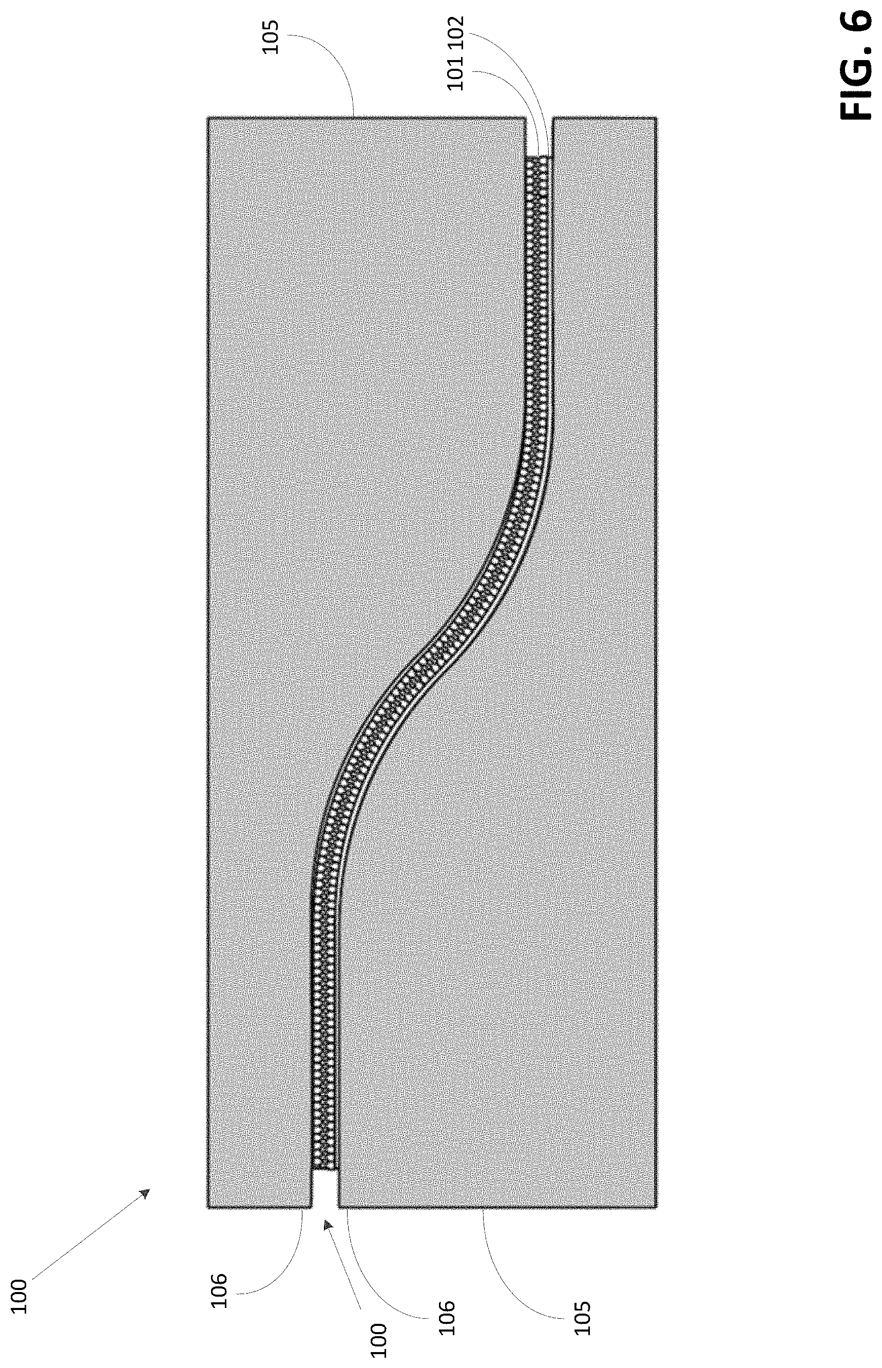
[0010] FIG. 6 shows an example fastening element.
[0011] FIG. 7 shows an example fastening element.
[0012] FIG. 8 shows an example fastening element.
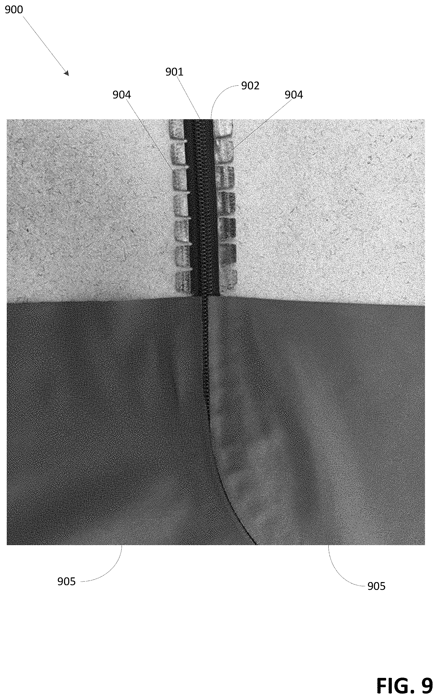
[0013] FIG. 9 shows an example fastening element.
[0014] FIG. 10 shows an example method.
DETAILED DESCRIPTION
[0015] An article may comprise a reversibly closeable, curved aperture between one or more segments, such as panels. A user may join or separate the segments by a fastening element, such as a slide fastener. The slide fastener may comprise a zipper. The fastening element may comprise a slider. The fastening element may comprise two sets of teeth configured to be matingly engaged by the slider. The fastening element may comprise two tapes coupled to the teeth. The fastening element may be coupled to one or more of the segments by one or more of the tapes. The tapes may comprise yarns, such as warp yarns. The yarns may run linearly in parallel with each other in a weaving direction or a knitting direction. The yarns may be substantially inelastic. As a result, adjusting yarn tension in the weaving direction or the knitting direction of the tapes, such as by attempting to bend or curve the tapes horizontally with respect to a tape surface, may cause one or more of the yarns to buckle. The buckling of the warp yarns may cause a wavy surface. The wavy surface may extend out of a plane relative of the planar surface of the un-deflected, at-rest tape.
[0016] A fastening element with reduced buckling may be formed by applying adhesive to the tapes. Cut-outs may be formed in the tapes, such as by dye-cutting or laser-cutting the tapes. The tapes may be bent, such as in a form of curved edges of panels of an article. The bent tape may be bonded to the edges of the panels.
[0017] FIG. 1 shows an example fastening element 100. The fastening element 100 may comprise a slide fastener, such as a zipper. The fastening element 100 may comprise one or more sets of teeth 101. The teeth may comprise a polymer, a metal, another material, or a combination thereof. Each of the sets of teeth 101 may comprise a plurality of matingly engageable fastener elements. The fastener elements of one set of teeth may be configured to matingly engage and disengage with the fastener elements of the other set of teeth 101.
[0018] The fastening element 100 may comprise a slider. The slider may comprise a polymer, a metal, another material, or a combination thereof. When the slider is moved in one direction relative to the teeth, the slider may urge the teeth in mating engagement. When the slider is moved in an opposite direction relative to the teeth, the slider may urge the teeth apart.
[0019] Each of the sets of teeth 101 may be coupled to a tape 102. The sets of teeth 101 may be bonded, sewn, or engageably coupled to the tape 102. The tape 102 may be substantially inelastic. The tape 102 may lay substantially flat on a tape surface. The tape 102 may lay substantially flat when a force is not acting on the tape 102.
[0020] The tape 102 may comprise a woven or knit substrate. The tape 102 may be woven to form a plurality of longitudinally juxtaposed segments extending laterally outward of a continuous segment. The segments may extend in a weaving (e.g., longitudinal) direction. The segments may be woven separately to form notches positioned there between. The segments may be woven to have finished perimeter edges. The finished perimeter edges may extend around an outer periphery of each segment. The finished perimeter edges extending around the outer periphery may lack tails and may not fray.
[0021] The tape 102 may comprise a plurality of panel warp yarns. The warp yarns may extend longitudinally from a finished edge of one of the substrate to an opposed finished edge the substrate. The warp yarns may have equivalent lengths. The warp yarns may have non-uniform lengths. The warp yarns of each segment may be relatively short compared to the warp yarns within the continuous segment. The warp yarns of each segment may extend only the length of the respective segment in the weaving (e.g., longitudinal) direction.
[0022] The tape 102 may comprise a plurality of continuous warp yarns positioned laterally adjacent each other to form the continuous segment. A set of warp yarns may be positioned laterally adjacent to each other and correspond to each segment. The set of warp yarns positioned laterally adjacent to each other may extend in a weaving direction parallel to the continuous warp yarns. The set of warp yarns may be longitudinally spaced apart from one or more adjacent sets of warp yarns.
[0023] FIG. 2 shows the fastening element 100. As shown in FIG. 2, adhesive 103 may be applied to the tape 102. The adhesive 103 may be applied to one side of the tape 102. The adhesive 103 may be extruded on the tape 102. The adhesive 103 may comprise a bead, a film, a tape, or a line of adhesive that may be extruded. The adhesive 103 may be heated, such as to melt. The heated adhesive 103 may be applied to the tape 102. The adhesive 103 may cool and harden on the tape 102. The adhesive 103 may comprise a liquid form. The adhesive 103 in the liquid form may be applied to the tape 102. The liquid adhesive 103 may dry and/or harden on the tape 102.
[0024] FIG. 3 shows the fastening element 100. As shown in FIG. 3, cut-outs 104 may be formed in the tape 102 of the fastening element 100. The cut-outs 104 may comprise a repeating pattern. The cut-outs 104 may comprise juxtaposed notches. The juxtaposed notches may be arranged lengthwise (e.g., longitudinally) along an edge of the tape 102.
[0025] The cut-outs 104 may be formed by dye-cutting or laser-cutting the tape 102. The cut-outs 104 may be formed by knitting the tape 102, such as by warp-knitting the tape. If the cut-outs 104 are knit, the spaces or gaps between sets of warp yarns may define the space and shape of the cut-outs 104. The cut-outs 104 may reduce buckling of the tape 102 as it is bent. The cut-outs 104 may enable the tapes 102 to be curved in-plane without buckling or deformation of the tapes 102 out-of-plane.
[0026] FIG. 4 shows the fastening element 100. As shown in FIG. 4, the fastening element 100 may be bent. The cut-outs 104 may facilitate the bending of the fastening element 100. The cut-outs 104 may reduce buckling of the tapes 102 as the fastening element is bent. The cut-outs 104 may enable the tapes 102 to be curved in-plane without buckling of the tapes 102 out-of-plane. The fastening element 100 may be bent in a curved shape. The curved shape may be similar to a curved shape of an edge of a component of an article.
[0027] FIG. 5 shows the fastening element 100 coupled to panels 105. The panels 105 may each comprise a longitudinal edge 106. The longitudinal edges 106 may comprise peripheral edges. The longitudinal edges 106 may be finished. For example, the longitudinal edges 106 may lack tails. The finished edges 106 may be configured to maintain structural integrity of the panels 105. For example, traditional panels that do not have finished edges and/or have cut-outs may fray or unravel.
[0028] The panels 105 may comprise a first panel 105 positioned opposite a second panel 105. The panels 105 may comprise respective portions of a single construct. A first of the panels 105 may comprise a portion of a first construct and a second of the panels 105 may comprise a portion of a second construct. The first construct and the second construct may be joined at a seam.
[0029] The panels 105 may each define continuous panel segments. The panels 105 may each define a plurality of longitudinally juxtaposed panel segments extending laterally outward from the continuous panel segment. The continuous panel segment may define a finished perimeter edge. The continuous panel segment may be separated from the adjacent panel segment by a gap between respectively opposed finished perimeter edges.
[0030] The panels 105 may comprise a textile. For example, the panels 105 may comprise a knitted textile, a woven textile, a felted textile, or a combination thereof. The panels 105 may comprise a synthetic material, such as polyester, acrylic, and nylon. The panels 105 may comprise an organic material, such as cotton or wool. The panels 105 may comprise a blend of synthetic and organic materials.
[0031] The fastening element 100 may be bent in a curved shape corresponding to longitudinal edges 106 of the panels 105. The tapes 102 of the fastening element may be bonded to the longitudinal edges 106. The tapes 102 may be bonded to the longitudinal edges 106 by the adhesive 103. For example, the tapes 102 may be applied to the longitudinal edges 106 such that the adhesive is in contact with the longitudinal edges 106. The tapes 102 may bond to the longitudinal edges 106 based on the adhesive drying and/or cooling and hardening. The fastening element 100 may define a curvilinear gap between the longitudinal edges 106. The curvilinear gap may extend from a first terminal end of the longitudinal edges 106 to a second terminal end of the longitudinal edges 106. The curvilinear gap may vary between the first terminal end and the second terminal end. The curvilinear gap may define an inflection point between the first terminal end and the second terminal end.
[0032] FIG. 6 shows the fastening element 100 coupled to the panels 105. FIG. 6 shows an opposite site of the fastening element 100 and the panels 105 than the side shown in FIG. 5. As shown in FIG. 6, the cut-outs 104 may be bonded to one side of the panels 105. The cut-outs 104 may not be visible on the other side of the panels 105, such as a side of the panels configured to be in contact with the body of a wearer of a garment comprising the panels.
[0033] FIG. 7 shows an example fastening element 700. The fastening element 700 may be similar to the fastening element 100 shown in FIGS. 1-6. Adhesive may be applied to tape 702 of the fastening element 700. The fastening element 700 may be bent in a curved shape corresponding to a shape of edges of panels 705. For example, as shown in FIG. 7, the curved shape may comprise a bell shape. The bent fastening element 700 may be bonded to panels 705 with the adhesive.
[0034] FIG. 8 shows an example fastening element 800. The fastening element 800 may be similar to the fastening element 100 shown in FIGS. 1-6. The fastening element may comprise teeth 801. The fastening element 800 may comprise a slider 807. The slider 807 may comprise a polymer, a metal, another material, or a combination thereof. The slider 807 may slidably engage the fastening element 800, such as by slidably engaging the teeth 701 of the fastening element 800. When the slider 807 is moved in one direction relative to the teeth 801, the slider 807 may urge the teeth 801 in mating engagement. When the slider 807 is moved in an opposite direction relative to the teeth 801, the slider 807 may urge the teeth 801 apart. The fastening element 800 may comprise a stopper 808. The stopper 808 may be configured to prevent the slider 807 from disengaging the teeth 801 and/or from separating from the fastening element 800.
[0035] Adhesive may be applied to tape 802 of the fastening element 800. The fastening element 800 may be bent in a curved shape corresponding to a shape of edges of panels 805. For example, as shown in FIG. 8, the curved shape may comprise a circular shape. The bent fastening element 800 may be bonded to panels 805 with the adhesive.
[0036] FIG. 9 shows an example fastening element 900. The fastening element 900 may be similar to the fastening element 100 shown in FIGS. 1-6. The fastening element 900 may be comprise teeth 901. The teeth 901 may be coupled to tape 902. The tape 902 may comprise cut-outs 904. The tape 902 may be bonded to panels 905 of an article. The tape 902 may be bonded to the panels 905 along longitudinal edges of the panels 905. For example, FIG. 9 shows the tape 902 bonded to an underside of the panels 905. As shown in FIG. 9, the fastening element 900 may extend past the panels 905.
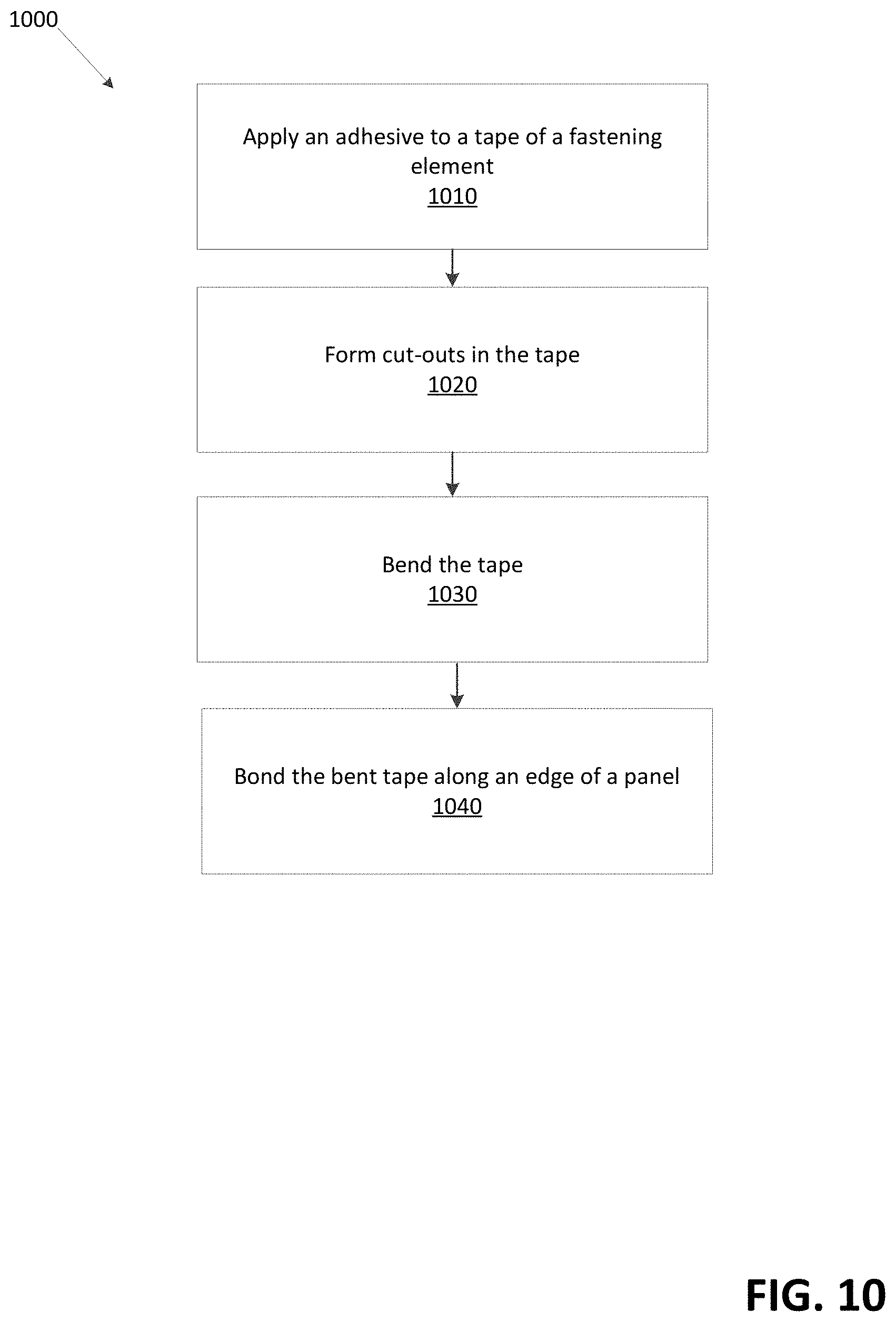
[0037] FIG. 10 shows an example method. At step 1010, an adhesive may be applied to a tape of a fastening element. The fastening element may be similar to any of the fastening element 100 in FIGS. 1-6, the fastening element 700 in FIG. 7, the fastening element 800 in FIG. 8, or the fastening element 900 in FIG. 9. The fastening element may comprise teeth. The fastening element may comprise a slider coupled to the teeth. The fastening element may comprise tape coupled to the teeth.
[0038] The tape may comprise two sides. The adhesive may be applied to one side of the tape. The adhesive may be extruded on the tape. The adhesive may comprise a bead, a film, a tape, or a line of adhesive that may be extruded. The adhesive may be heated, such as to melt. The heated adhesive may be applied to the tape. The adhesive may cool and harden on the tape. The adhesive may comprise a liquid form. The adhesive in the liquid form may be applied to the tape. The liquid adhesive may dry and/or harden on the tape.
[0039] At step 1020, cut-outs may be formed in the tape. The cut-outs may be formed by dye-cutting or laser-cutting the tape. The cut-outs may comprise a repeating pattern. The cut-outs may comprise juxtaposed notches. The juxtaposed notches may be arranged lengthwise (e.g., longitudinally) along an edge of the tape. The cut-outs may reduce buckling of the tape as it is bent. The cut-outs may enable the tape to be curved in-plane without buckling of the tape out-of-plane.
[0040] At step 1030, the tape may be bent. The tape may be bent in a curved shape. The curved shape may be similar to a curved shape of an edge of a component of an article. For example, the tape may be bent in a shape corresponding to a shape of an edge of a panel of the article.
[0041] At step 1040, the bent tape may be bonded along an edge of a panel. The bent tape may be bonded using the adhesive. For example, the adhesive on the tape may be heated and/or melted. The heated and/or melted adhesive may be put in contact with the edge of the panel. The adhesive may cool and/or harden on the edge of the panel. The panel may comprise a portion of an article. The article may comprise a garment, such as a jacket, a sweater, a dress, pants, shorts, a shirt, or a jumpsuit. The article may comprise a sporting good, such as a tent, a canopy, or a backpack. The article may comprise a luggage item, such as a suitcase, a purse, a garment bag, a toiletry bag, or a duffel bag. The article may comprise a furniture item, such as a chair, a couch, a mattress, or other furniture having a permanent or removable cover. The article may comprise footwear, such as boots, sneakers, or sandals. The article may comprise any article of manufacture that desirably incorporates a reversibly closeable, curved aperture.
* * * * *
D00000
D00001
D00002
D00003
D00004
D00005
D00006
D00007
D00008
D00009
D00010
XML
uspto.report is an independent third-party trademark research tool that is not affiliated, endorsed, or sponsored by the United States Patent and Trademark Office (USPTO) or any other governmental organization. The information provided by uspto.report is based on publicly available data at the time of writing and is intended for informational purposes only.
While we strive to provide accurate and up-to-date information, we do not guarantee the accuracy, completeness, reliability, or suitability of the information displayed on this site. The use of this site is at your own risk. Any reliance you place on such information is therefore strictly at your own risk.
All official trademark data, including owner information, should be verified by visiting the official USPTO website at www.uspto.gov. This site is not intended to replace professional legal advice and should not be used as a substitute for consulting with a legal professional who is knowledgeable about trademark law.