Packaging
McKenzie; Aaron ; et al.
U.S. patent application number 16/096889 was filed with the patent office on 2020-07-09 for packaging. The applicant listed for this patent is NICOVENTURES HOLDINGS LIMITED. Invention is credited to Andy DRAY, Aaron McKenzie.
| Application Number | 20200214341 16/096889 |
| Document ID | / |
| Family ID | 56234194 |
| Filed Date | 2020-07-09 |


View All Diagrams
| United States Patent Application | 20200214341 |
| Kind Code | A1 |
| McKenzie; Aaron ; et al. | July 9, 2020 |
PACKAGING
Abstract
Packaging comprises a sleeve and a re-configurable container comprising first and second boxes which are hinged together and are pivotable between a folded-together configuration in which a first main panel of the first box faces a first main panel of the second box and the container is insertable into and removable from the sleeve and an unfolded configuration in which the first main panels of the first and second boxes do not face one another. The first main panel of the first box has an aperture which provides access to a first compartment. The second box has a first edge panel for providing access to a second compartment. The arrangement is such that, when the container is inserted in the sleeve, the sleeve covers the first edge panel of the second box, and, when the container is removed from the sleeve, the first edge panel of the second box provides access to the second compartment.
| Inventors: | McKenzie; Aaron; (London, GB) ; DRAY; Andy; (London, GB) | ||||||||||
| Applicant: |
|
||||||||||
|---|---|---|---|---|---|---|---|---|---|---|---|
| Family ID: | 56234194 | ||||||||||
| Appl. No.: | 16/096889 | ||||||||||
| Filed: | April 28, 2017 | ||||||||||
| PCT Filed: | April 28, 2017 | ||||||||||
| PCT NO: | PCT/GB2017/051202 | ||||||||||
| 371 Date: | October 26, 2018 |
| Current U.S. Class: | 1/1 |
| Current CPC Class: | B65D 5/0085 20130101; B65D 2581/05 20130101; B65D 2585/86 20130101; A24F 15/01 20200101; B65D 5/5028 20130101; B65D 5/38 20130101; B65D 77/042 20130101 |
| International Class: | A24F 15/01 20060101 A24F015/01; B65D 5/00 20060101 B65D005/00; B65D 5/38 20060101 B65D005/38; B65D 5/50 20060101 B65D005/50 |
Foreign Application Data
| Date | Code | Application Number |
|---|---|---|
| Apr 29, 2016 | GB | 1607580.6 |
Claims
1. Packaging comprising: a sleeve; and a re-configurable container comprising a first box and a second box which are hinged together and are pivotable between (i) a folded-together configuration in which a first main panel of the first box faces a first main panel of the second box and the container is insertable into and removable from the sleeve and (ii) an unfolded configuration in which the first main panel of the first box and the first main panel of the second box do not face one another; wherein the first main panel of the first box has an aperture which provides access to a first compartment; the second box has a first edge panel for providing access to a second compartment; and the arrangement is such that, when the container is inserted in the sleeve, the sleeve covers the first edge panel of the second box, and, when the container is removed from the sleeve, the first edge panel of the second box provides access to the second compartment.
2. The packaging according to claim 1, wherein: the first box and the second box each comprise the respective first main panel, a second main panel opposed to the first main panel, a first edge panel, a second edge panel, a third edge panel and a fourth edge panel; and a hinge panel connects the second main panel of the first box with the second main panel of the second box.
3. The packaging according to claim 1, wherein: a tray is positioned inside the first compartment of the first box and has a well which is positioned underneath the aperture of the first main panel of the first box.
4. The packaging according to claim 3, wherein: the tray is sandwiched between the first main panel and the second main panel of the first box and the tray has sides which abut against the first edge panel, the second edge panel, the third edge panel and the fourth edge panel of the first box.
5. The packaging according to claim 3, wherein: the tray has a platform surface which abuts against the first main panel of the first box; and the platform surface comprises an outer annulus which extends around the well of the tray.
6. The packaging according to claim 5, wherein: the aperture of the first main panel of the first box is wider than the well of the tray, such that an inner annular strip of the outer annulus of the platform surface is visible through the aperture of the first main panel of the first box.
7. The packaging according to claim 1, wherein: the first edge panel of the second box is a closeable flap.
8. The packaging according to claim 1, wherein: the container is formed from a single blank.
9. The packaging according to claim 1, wherein: a vaping device is stored in the first compartment.
10. The packaging according to claim 9, wherein: a tray is positioned inside the first compartment of the first box and has a well which is positioned underneath the aperture of the first main panel of the first box; and the vaping device is nested in the well of the tray.
11. The packaging according to claim 1, further comprising: an insert which is insertable into and removable from the second compartment via the first edge panel of the second box; wherein the second box has a second main panel opposed to its first main panel and a second edge panel opposed to its first edge panel; the insert comprises a third box with a third compartment defined between a first main panel opposing a second main panel and a first edge panel opposing a second edge panel; the first main panel of the third compartment extends beyond at least one of the first edge panel or the second edge panel of the third compartment to provide at least one of a first bracing projection or a second bracing projection; and the arrangement is such that, when the insert is in the second compartment, the first main panel and the second main panel of the third compartment are co-planar with and abut against the first main panel and the second main panel of the second box and the at least one bracing projection holds the third compartment at a position in the second compartment spaced away from the at least one of the first edge panel or the second edge panel of the second box.
12. The packaging according to claim 11, wherein: the first main panel of the third compartment includes the first bracing projection and the second bracing projection; and the arrangement is such that, when the insert is in the second compartment, the first bracing projection and the second bracing projection hold the third compartment at a central position in the second compartment between the first edge panel of the second box and the second edge panel of the second box.
13. The packaging according to claim 11, wherein: the third box has a third edge panel and a fourth edge panel extending in the direction of insertion of the insert into the second compartment; the third edge panel of the third box is a flap for providing access to the third compartment; and the arrangement is such that, when the insert is in the second compartment, an edge panel of the second box covers the third edge panel of the third box, and, when the insert is removed from the second compartment, the third edge panel of the third box provides access to the third compartment.
14. The packaging according to claim 13, wherein: the insert includes a divider which divides the third compartment of the third box into a first sub-compartment and a second sub-compartment; the divider extends in a direction transverse to the direction of insertion of the insert into the second compartment; and the third edge panel of the third box provides access to both the first sub-compartment and the second sub-compartment.
15. The packaging according to claim 11, wherein: the third box has a third edge panel and a fourth edge panel extending in the direction of insertion of the insert into the second compartment; the third edge panel of the third box is a flap for providing access to the third compartment; the fourth edge panel of the third box is a flap for providing access to the third compartment; and the arrangement is such that, when the insert is in the second compartment, edge panels of the second box cover the third edge panel and the fourth edge panel of the third box, and, when the insert is removed from the second compartment, the third edge panel and the fourth edge panel of the third box provide access to the third compartment.
16. The packaging according to claim 15, wherein: the insert includes a divider which divides the third compartment of the third box into a first sub-compartment and a second sub-compartment; the divider extends in the direction of insertion of the insert into the second compartment; the third edge panel of the third box provides access to the first sub-compartment; and the fourth edge panel of the third box provides access to the second sub-compartment.
17. The packaging according to claim 11, wherein: the insert is formed from a single blank.
18. The packaging according to claim 11, wherein: the third compartment contains one or more of a charger for a vaping device, an e-liquid bottle for resupplying a vaping device with e-liquid, and an instruction booklet for a vaping device.
19. A blank for forming the container of claim 1.
20. A blank for forming the insert of claim 11.
21. A method of forming a container for packaging, comprising: providing a blank for a container; and folding the blank to form the container of claim 1.
22. A method of forming an insert for packaging, comprising: providing a blank for an insert; and folding the blank to form the insert of claim 11.
23. A method of forming packaging, comprising: providing a blank for a sleeve; providing a blank for a container; providing a blank for an insert; and folding the blanks to form the sleeve, the container, and the insert, wherein the container comprises: a first box and a second box which are hinged together and are pivotable between (i) a folded-together configuration in which a first main panel of the first box faces a first main panel of the second box and the container is insertable into and removable from the sleeve and (ii) an unfolded configuration in which the first main panel of the first box and the first main panel of the second box do not face one another, wherein the first main panel of the first box has an aperture which provides access to a first compartment, the second box has a first edge panel for providing access to a second compartment, and the arrangement is such that, when the container is inserted in the sleeve, the sleeve covers the first edge panel of the second box, and, when the container is removed from the sleeve, the first edge panel of the second box provides access to the second compartment; and wherein the insert is insertable into and removable from the second compartment via the first edge panel of the second box, and the second box has a second main panel opposed to its first main panel and a second edge panel opposed to its first edge panel, and wherein the insert comprises: a third box with a third compartment defined between a first main panel opposing a second main panel and a first edge panel opposing a second edge panel, the first main panel of the third compartment extends beyond at least one of the first edge panel or the second edge panel of the third compartment to provide at least one of a first bracing projection or a second bracing projection, and the arrangement is such that, when the insert is in the second compartment, the first main panel and the second main panel of the third compartment are co-planar with and abut against the first main panel and the second main panel of the second box and the at least one bracing projection holds the third compartment at a position in the second compartment spaced away from the at least one of the first edge panel or the second edge panel of the second box.
24. (canceled)
Description
PRIORITY CLAIM
[0001] The present application is a National Phase entry of PCT Application No. PCT/GB2017/051202, filed Apr. 28, 2017, which claims priority from GB Patent Application No. 1607580.6, filed Apr. 29, 2016, each of which is hereby fully incorporated herein by reference.
TECHNICAL FIELD
[0002] The present disclosure relates to packaging.
BACKGROUND
[0003] Packaging may be used to protect a product prior to use by a user and to contain ancillary items related to the product that will be needed by the user when using the product.
[0004] For example, when the product is a vaping device, the packaging may contain the vaping device and ancillary items such as a charger for the vaping device and an instruction booklet for the vaping device.
SUMMARY
[0005] According to some embodiments described herein, there is provided packaging comprising: a sleeve; and a re-configurable container comprising first and second boxes which are hinged together and are pivotable between (i) a folded-together configuration in which a first main panel of the first box faces a first main panel of the second box and the container is insertable into and removable from the sleeve and (ii) an unfolded configuration in which the first main panels of the first and second boxes do not face one another; wherein the first main panel of the first box has an aperture which provides access to a first compartment; the second box has a first edge panel for providing access to a second compartment; and the arrangement is such that, when the container is inserted in the sleeve, the sleeve covers the first edge panel of the second box, and, when the container is removed from the sleeve, the first edge panel of the second box provides access to the second compartment.
[0006] The packaging may provide an attractive and secure way of storing a product and ancillary items. By looking at the packaging, the user may understand that the container may be removed from the sleeve, in the same way that it is intuitive to a reader of a book that a book may be removed from its slipcase prior to reading the book.
[0007] When the container has been removed from the sleeve, the user may understand, from looking at the container, that the container may be folded open, in the same way that is it intuitive to the reader of the book that, having removed the book from its slipcase, the book may now be opened so that it may be read.
[0008] A product such as a vaping device may be stored in the first compartment, and ancillary items may be stored in the second compartment. When the container has been folded open, the vaping device may be removed from the first compartment through the aperture of the first compartment. Also, the second compartment is accessible, because the first edge panel of the second box is no longer covered by the sleeve, and the ancillary items may be removed from the second compartment via the first edge panel of the second box so that the ancillary items are available to support the use of the vaping device.
[0009] In contrast, when the container is in its folded-together configuration and is stored in the sleeve, the first compartment and the second compartment are not accessible. The aperture in the first main panel of the first box which would otherwise give access to the first compartment is covered by the first main panel of the second box. The second compartment is not accessible because the sleeve is covering the first edge panel of the second box. Thus, whatever is stored in the first and second compartments is securely stored as it cannot fall out of the first and second compartments.
[0010] In some embodiments, the first and second boxes each comprise the first main panel, a second main panel opposed to the first main panel, and first to fourth edge panels. A hinge panel may connect the second main panels of the first and second boxes.
[0011] Because the hinge panel extends between the second main panels of the first and second boxes, it may have a width which is generally at least the sum of the depth dimension of the first box and the depth dimension of the second box, in order to permit the container to adopt the folded-together configuration in which the first box is folded against the second box. Because of this width of the hinge panel, the hinge panel serves to space the first box apart from the second box when the container is in the unfolded configuration. For example, the unfolded first and second boxes may be laid flat on a surface, and the hinge panel will space apart the first and second boxes by the width of the hinge panel, and this helps to make a visual distinction (a gap) between the two boxes whilst still maintaining a neat and tidy relative positioning of each box relative to the other box by means of the guidance (the positional framework) provided by the hinge panel. Advantage may be taken of the surface of the hinge panel which is exposed to view when the container is in the unfolded configuration by, for example, printing information on that surface such as instructions to remove the product from the first compartment and the ancillary items from the second compartment.
[0012] In some embodiments, a tray is positioned inside the first compartment of the first box. The tray may have a well which is positioned underneath the aperture of the first main panel of the first box.
[0013] The well may be formed to fit around a particular product which it is desired to store in the first compartment. By producing a range of trays with differently-shaped wells, a range of different products may be stored in the first compartment depending on which particular style of tray is selected to be used in the first compartment. The aperture of the first main panel of the first box may be made wider than the widest well of the range of trays, and thus it would not be necessary to alter the aperture when switching between using different ones of the range of trays.
[0014] In some embodiments, the tray is sandwiched between the first and second main panels of the first box. The tray may have sides which abut against the first to fourth edge panels of the first box.
[0015] In this way, the tray may be held in position internally of the first box without, for example, needing to be glued or fastened to an internal surface of the first compartment. Thus, the fabrication of the packaging may be simplified.
[0016] In some embodiments, the tray has a platform surface which abuts against the first main panel of the first box. The platform surface may comprise an outer annulus which extends around the well of the tray. The platform surface may also include one or more dividers which project into the well. These divider(s) may be used to partition the well into a plurality of zones for receiving a plurality of products in the well instead of just one product.
[0017] The plurality of products may be, for example, components of a vaping device which, when removed from the well, may be assembled together.
[0018] The outer annulus of the platform surface may provide at least 10%, or at least 15%, or at least 20% of the area of the upper face of the tray.
[0019] In some embodiments, the aperture of the first main panel of the first box is wider than the well of the tray. An inner annular strip of the outer annulus of the platform surface may be visible through the aperture of the first main panel of the first box. The inner annular strip may have a width of from 2 mm to 10 mm, for example from 2 mm to 7 mm, or for example from 2 mm to 5 mm. The inner annular strip serves to space the aperture of the first main panel of the first box away from the well so that the user of the packaging is less likely to snag his or her fingers or thumb on the material of the first main panel when removing a product from the well or when returning a product into the well.
[0020] In some embodiments, the first edge panel of the second box is a closeable flap. In other embodiments, the first edge panel of the second box incorporates a line of weakness, such as a line of perforations, which may be ruptured in order to open the first edge panel and thereby provide access into the second compartment of the second box.
[0021] In some embodiments, the container is formed from a single blank.
[0022] In some embodiments, a vaping device is stored in the first compartment. The vaping device may be nested in the well of the tray. The shape of the well of the tray may match the shape of the vaping device around at least 50% of the periphery of the well, for example around at least 60%, 70%, 80% or 90% of the periphery of the well. The higher the percentage, the better the grip of the well on the vaping device.
[0023] In some embodiments, the packaging further comprises: an insert which is insertable into and removable from the second compartment via the first edge panel of the second box; wherein the second box has a second main panel opposed to its first main panel and a second edge panel opposed to its first edge panel; the insert comprises a third box with a third compartment defined between opposed first and second main panels and opposed first and second edge panels; the first main panel of the third compartment extends beyond the first and/or second edge panels of the third compartment to provide first and/or second bracing projections; and the arrangement is such that, when the insert is in the second compartment, the first and second main panels of the third compartment are co-planar with and abut against the first and second main panels of the second box and the bracing projection(s) hold the third compartment at a position in the second compartment spaced away from the first and/or second edge panels of the second box.
[0024] Ancillary items may be indirectly stored in the second compartment by being stored in the third compartment of the insert, and by the insert being inserted into the second compartment. The volume needed by the ancillary items may be less than the volume of the second compartment. The volume of the third compartment is less than the volume of the second compartment and may be matched to the volume required by the ancillary items. The bracing projection(s) hold the third compartment in position in the second compartment to stop the insert sliding up and down internally inside the second compartment, whilst at the same time the third compartment, being matched in size/volume to the size/volume required by the ancillary items, reduces the movement that may be experienced by the ancillary items in response to shaking of the packaging.
[0025] When the insert is being inserted into the second compartment, the insert is stabilized and guided as it is inserted because the first and second main panels of the third compartment of the insert are co-planar with and abut against the first and second main panels of the second box.
[0026] In some embodiments, the first main panel of the third compartment includes the first and second bracing projections; and the arrangement is such that, when the insert is in the second compartment, the first and second bracing projections hold the third compartment at a central position in the second compartment between the first and second edge panels of the second box.
[0027] Each of the first and second bracing projections may project from the third compartment by a distance which is at least 5% or at least 10% or at least 15% or at least 20% of the length of the second compartment in the direction of insertion of the insert into the second compartment.
[0028] In some embodiments, the third box has third and fourth edge panels extending in the direction of insertion of the insert into the second compartment; the third edge panel of the third box is a flap for providing access to the third compartment; and the arrangement is such that, when the insert is in the second compartment, an edge panel of the second box covers the third edge panel of the third box, and, when the insert is removed from the second compartment, the third edge panel of the third box provides access to the third compartment.
[0029] When the insert is in the second compartment of the second box, the third compartment is not accessible. The third edge panel of the third box which would otherwise give access to the third compartment is covered by the overlying edge panel of the second box. Thus, whatever is stored in the third compartment is securely stored as it cannot fall out of the third compartment. The contents of the third compartment may be accessed and removed by first of all removing the insert from the second compartment, and then opening the flap which is the third edge panel of the third box.
[0030] The arrangement may be such that, when the insert is in the second compartment, the third edge panel of the third box is co-planar with and abuts against the overlying edge panel of the second box.
[0031] In some embodiments, the insert includes a divider which divides the third compartment of the third box into first and second sub-compartments; the divider extends in a direction transverse to the direction of insertion of the insert into the second compartment; and the third edge panel of the third box provides access to both of the first and second sub-compartments.
[0032] In some embodiments, the third box has third and fourth edge panels extending in the direction of insertion of the insert into the second compartment; the third edge panel of the third box is a flap for providing access to the third compartment; the fourth edge panel of the third box is a flap for providing access to the third compartment; and the arrangement is such that, when the insert is in the second compartment, edge panels of the second box cover the third and fourth edge panels of the third box, and, when the insert is removed from the second compartment, the third and fourth edge panels of the third box provide access to the third compartment.
[0033] When the insert is in the second compartment of the second box, the third compartment is not accessible. The third and fourth edge panels of the third box which would otherwise give access to the third compartment are covered by the overlying edge panels of the second box. Thus, whatever is stored in the third compartment is securely stored as it cannot fall out of the third compartment. The contents of the third compartment may be accessed and removed by first of all removing the insert from the second compartment, and then opening one or both of the flaps which are the third and fourth edge panels of the third box.
[0034] The arrangement may be such that, when the insert is in the second compartment, the third and fourth edge panels of the third box are co-planar with and abut against the overlying edge panels of the second box.
[0035] In some embodiments, the insert includes a divider which divides the third compartment of the third box into first and second sub-compartments; the divider extends in the direction of insertion of the insert into the second compartment; the third edge panel of the third box provides access to the first sub-compartment; and the fourth edge panel of the third box provides access to the second sub-compartment.
[0036] In some embodiments, when the packaging includes the sleeve, the container and the insert, the arrangement is such that, in order to gain access to the contents of the third compartment, the container may be removed laterally from the sleeve, the insert may be removed longitudinally from the second compartment of the container, and the contents may be removed laterally from the third compartment of the insert.
[0037] In some embodiments, the insert is formed from a single blank.
[0038] In some embodiments, the third compartment contains one or more of a charger for a vaping device, an e-liquid bottle for resupplying a vaping device with e-liquid, and an instruction booklet for a vaping device.
BRIEF DESCRIPTION OF THE DRAWINGS
[0039] Embodiments of the disclosure will now be described, by way of example only, with reference to the accompanying drawings, in which:
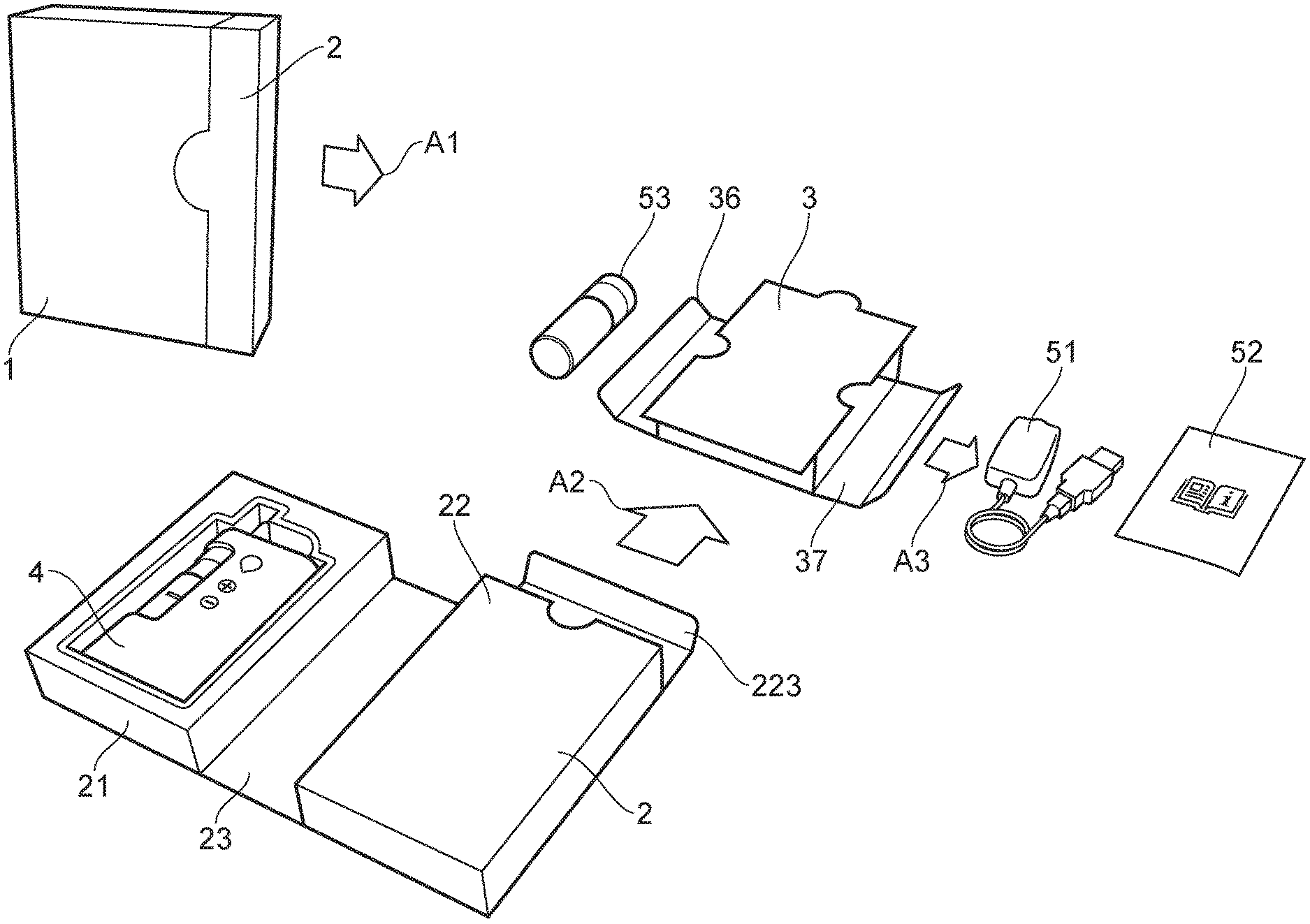
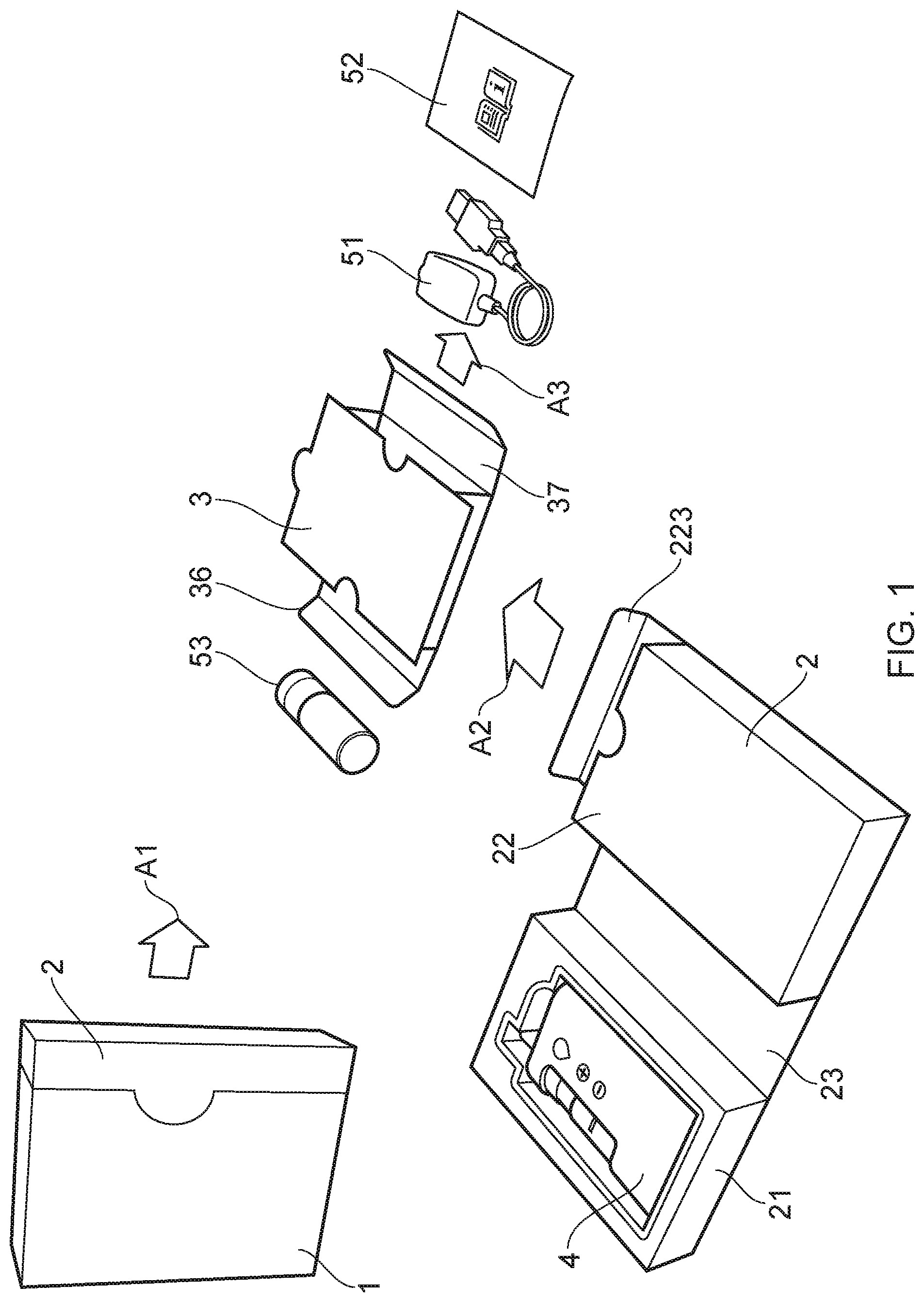
[0040] FIG. 1 is a schematic representation of how packaging in accordance with a first embodiment may be opened up, in sequence, by removing the folded-up container sideways out of the sleeve, by unfolding the container, by opening a top flap on the container, by removing the insert up out of the opened top flap of the container, by opening the side flaps of the insert, and by removing ancillary items out via the side flaps of the insert.
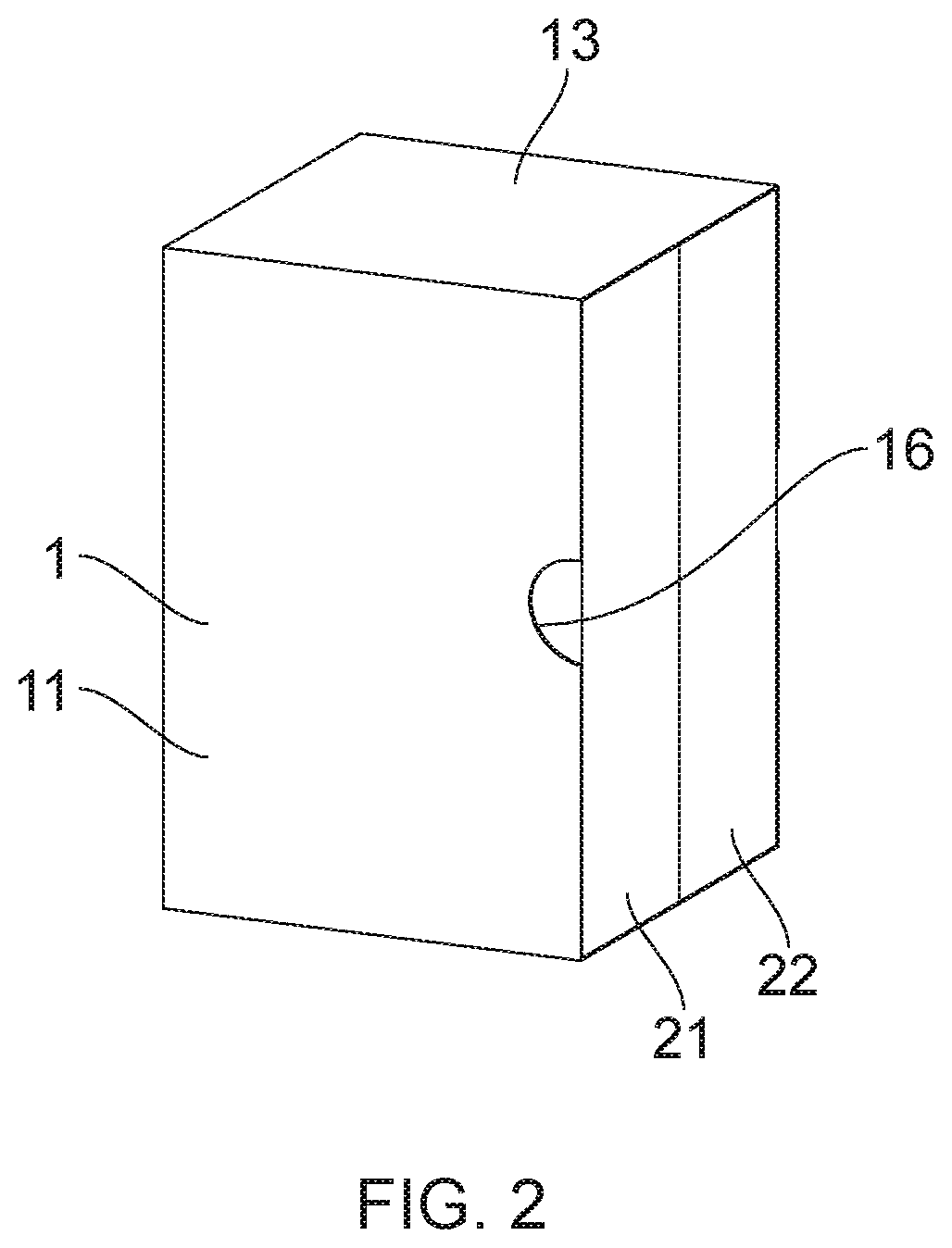
[0041] FIG. 2 is a perspective view of a sleeve of a second embodiment of the packaging.
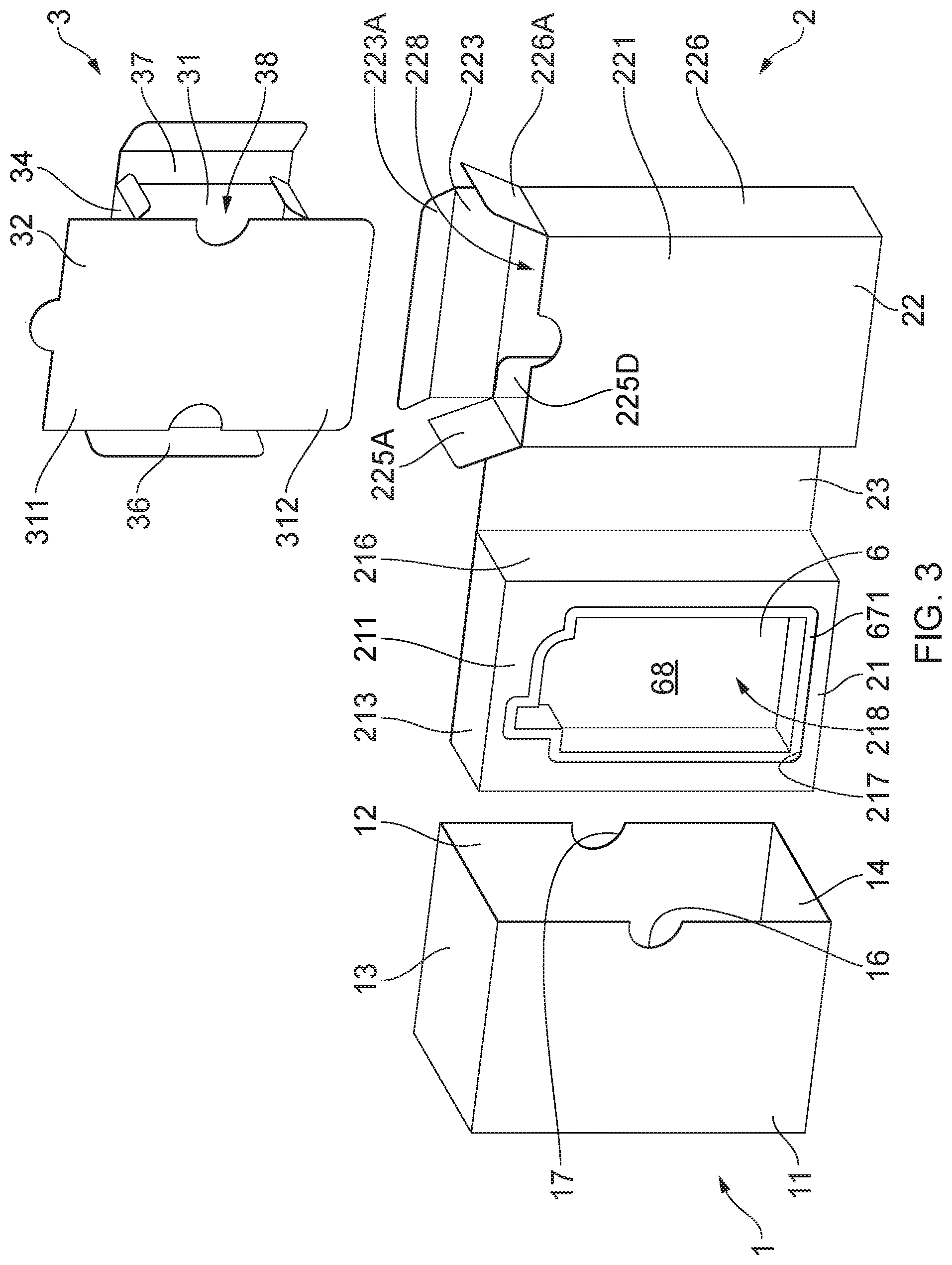
[0042] FIG. 3 is an exploded perspective view of the second embodiment, wherein the container has been removed from the sleeve and unfolded, and the insert has been removed from the container.
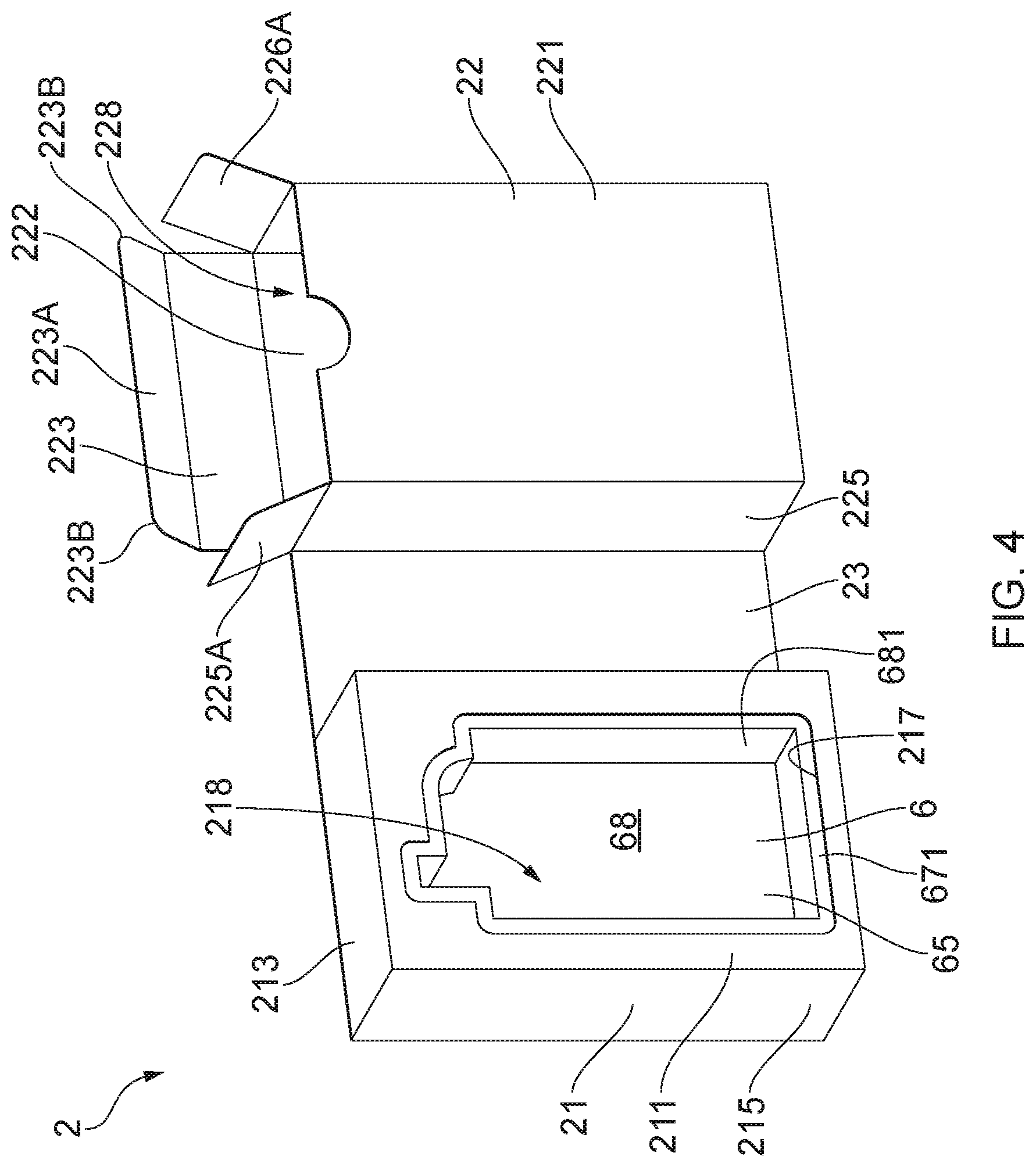
[0043] FIG. 4 is a perspective view of the unfolded container of the second embodiment.
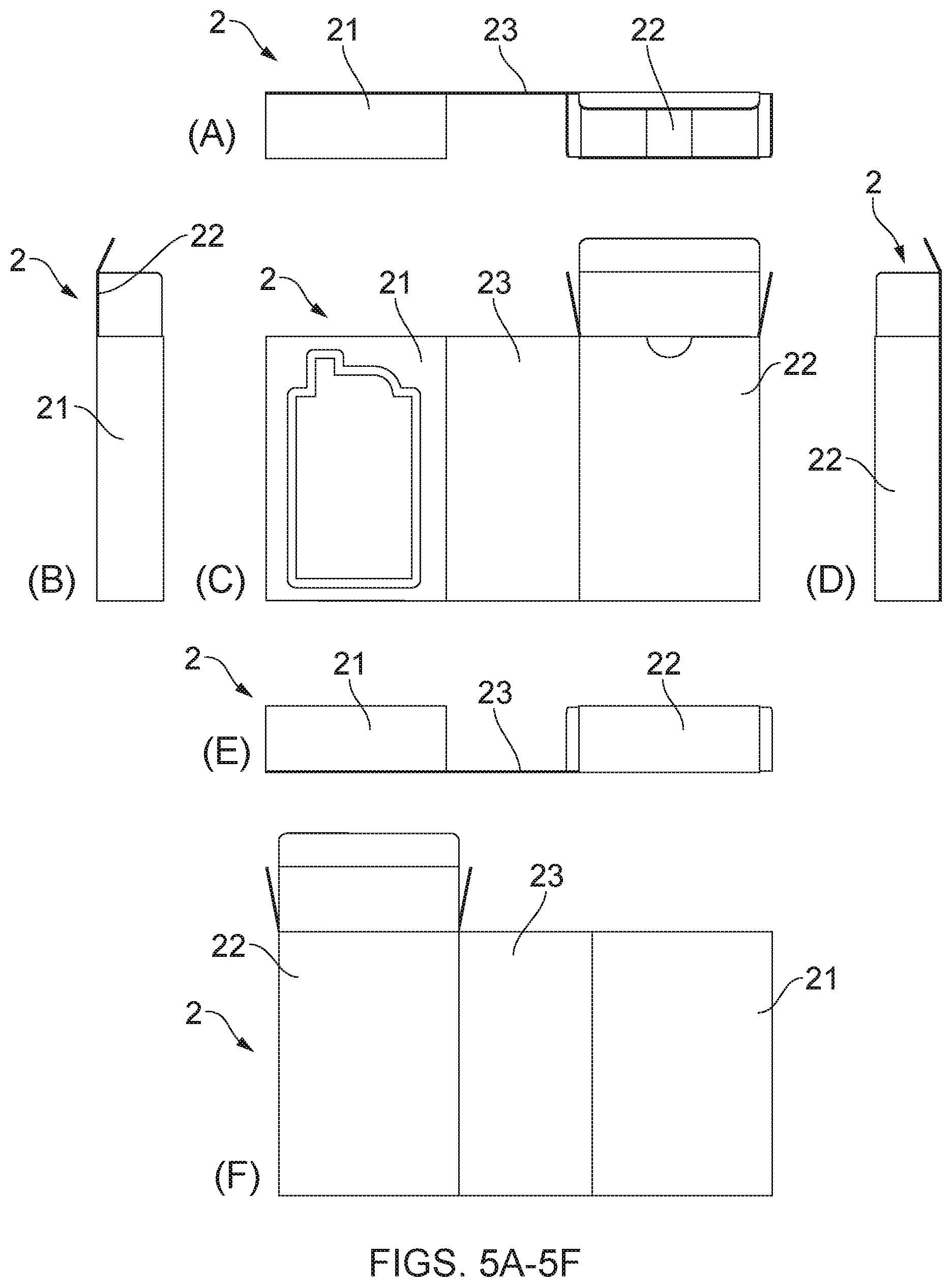
[0044] FIGS. 5A to 5F are respectively top, left side, front, right side, bottom and rear views of the unfolded container of the second embodiment.
[0045] FIG. 6 is a plan view of the blank used to form the container of the second embodiment.
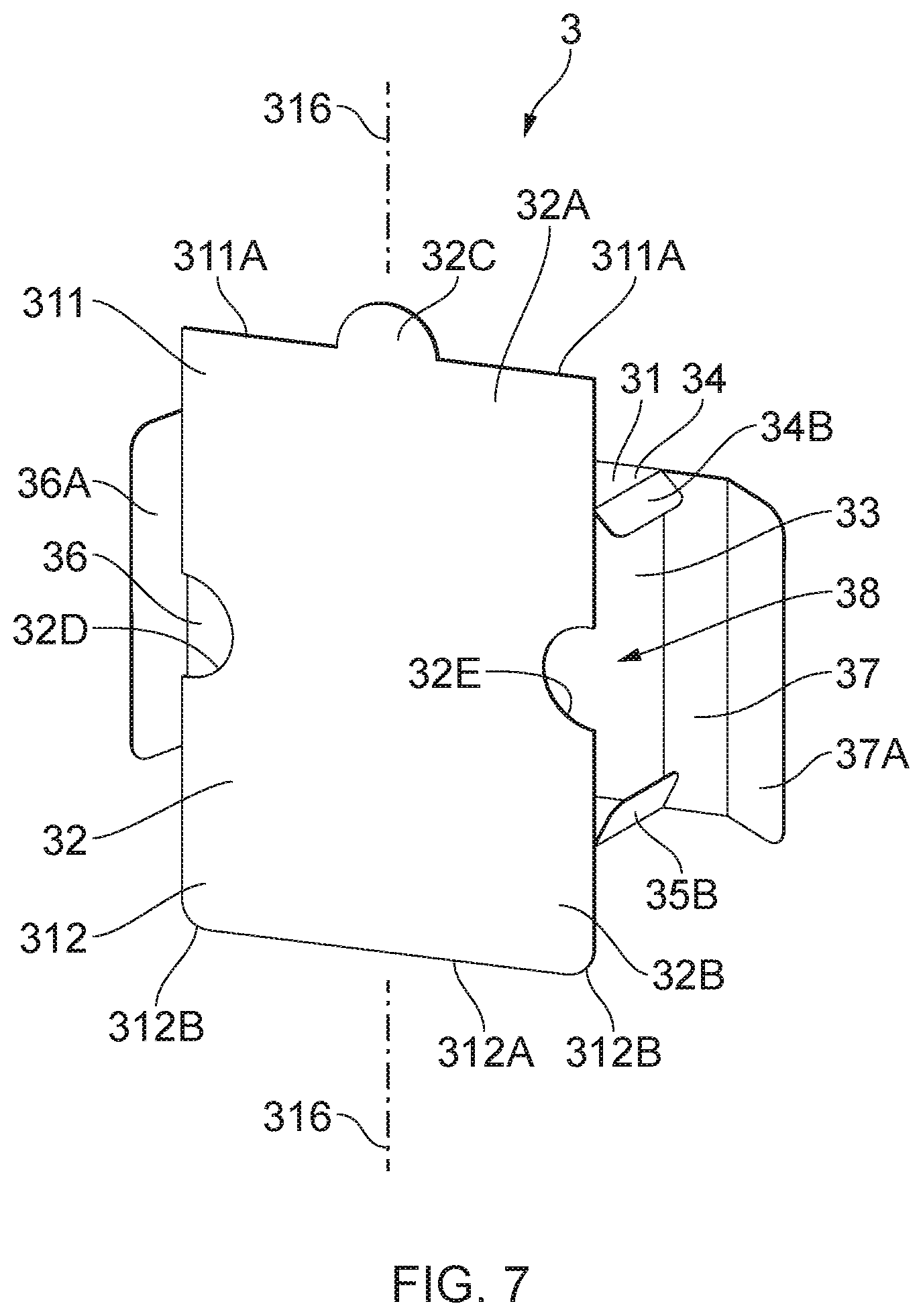
[0046] FIG. 7 is a perspective view of the insert of the second embodiment with its two side flaps open.
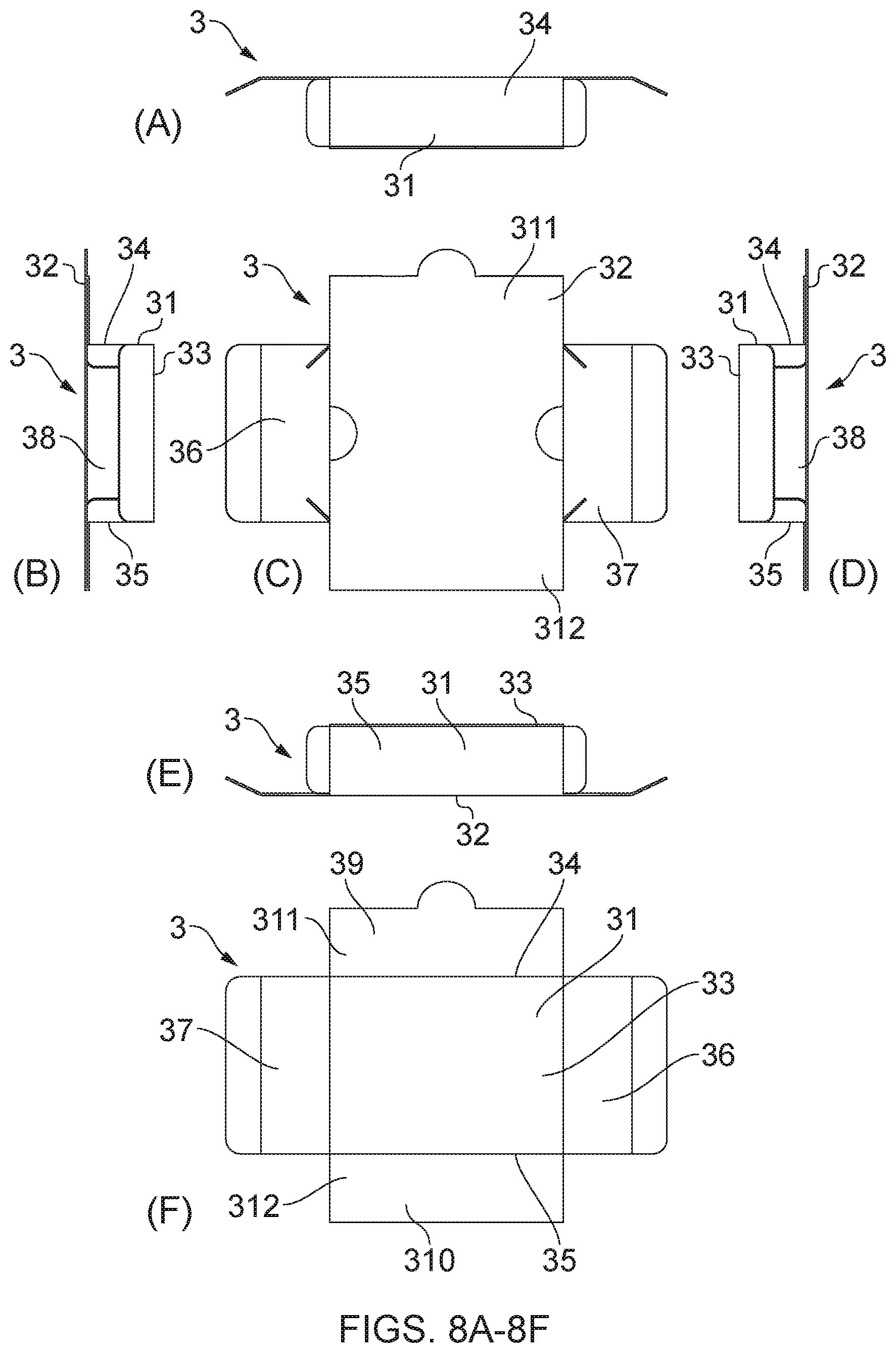
[0047] FIGS. 8A to 8F are respectively bottom, right side, front, left side, top and rear views of the insert of the second embodiment with its two side flaps open.
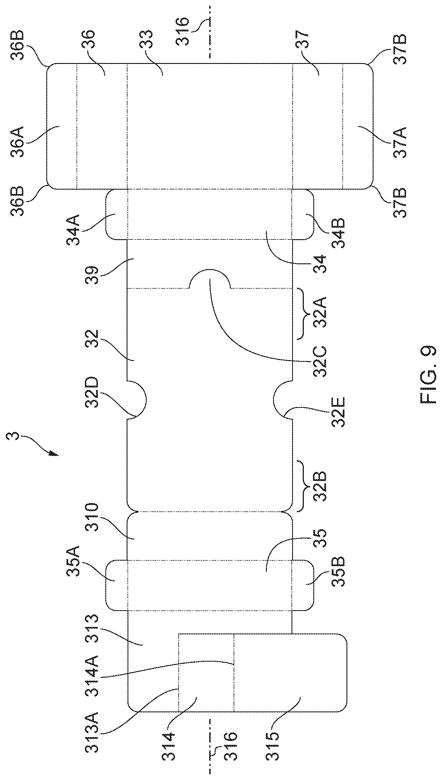
[0048] FIG. 9 is a plan view of the blank used to form the insert of the second embodiment.
[0049] FIG. 10 is a plan view of the blank used to form the sleeve of the second embodiment.
[0050] FIGS. 11A and 11B are respectively a plan view and a sectional view on the line A-A of the tray of the second embodiment.
[0051] FIG. 12 shows the container and insert in exploded perspective view of a third embodiment of the packaging (but with the sleeve not being shown).
[0052] FIG. 13 shows the container and insert in exploded perspective view of a fourth embodiment of the packaging (but with the sleeve not being shown).
[0053] FIG. 14 shows the container and insert in exploded perspective view of a fifth embodiment of the packaging (but with the sleeve not being shown).
DETAILED DESCRIPTION
[0054] The first embodiment of the packaging shown in FIG. 1 of the drawings comprises a sleeve 1, a container 2 and an insert 3. Initially, the insert 3 is housed in the container 2, and the container 2 is housed in the sleeve 1.
[0055] The container 2 may be removed from the sleeve 1 by sliding the container 2 out laterally (arrow A1) relative to the longitudinal axis of the sleeve 1 (the generally vertical axis in FIG. 1). As shown, the container 2 may then be opened up (like opening a book) by folding apart first and second boxes 21, 22 of the container 2 which are connected by a hinge panel 23. A product in the form of a vaping device 4 is stored in the first box 21 and may be lifted out of the first box 21. The insert 3 is stored in the second box 22 and may be removed by sliding the insert up out of the second box 22 in the longitudinal direction (arrow A2) of the container 2. When the insert 3 has been fully removed from the second box 22, various ancillary items of the vaping device 4 (in the form of a charger 51, an instruction booklet 52, and an e-liquid bottle 53) may be removed laterally (arrow A3 and in the opposite direction) relative to the longitudinal axis of the insert 3 out of the sides of the insert 3. Thus, the movement of the ancillary items in the overall process is "lateral" (arrow A1), "longitudinal" (arrow A2) and then "lateral" (arrow A3) again, and this assists with keeping the ancillary items securely stored prior to use, as will be explained in more detail below.
[0056] Reference is now made to the second embodiment of the packaging shown in FIGS. 2 to 11B. The second embodiment is similar to the first embodiment. The sleeve 1 of the second embodiment is shown in FIGS. 2, 3 and 10 and has first and second side panels 11, 12 and top and bottom panels 13, 14. The sleeve 1 is formed from a single blank (see FIG. 10) and the bottom panel 14 is of double thickness as it is formed from overlapping panels 14A, 14B of the blank which are stuck together by means of an adhesive patch 15 which is shown in FIG. 10. The assembled sleeve 1 has the form of a tube (with two open ends) but alternatively the blank used to form the sleeve 1 could be adapted to close one of the ends so that the sleeve resembles the slipcase of a book.
[0057] The sleeve 1 is provide with cut-outs 16, 17 in vertical edges of the first and second side panels 11, 12 in order to assist the user in gripping the container 2 when extracting the container 2 from the sleeve 1.
[0058] The sleeve 1 has the shape of a rectangular box because it is designed to receive the container 2 which is also rectangular, and the container 2 nests within the sleeve 1 as a close fit.
[0059] The container 2 will now be discussed in more detail with reference primarily to FIGS. 3 to 6. The container 2 is formed from a single blank (shown in FIG. 6) and the first box 21 of the container 2 has first and second main panels 211, 212 which form front and rear faces of the first box 21 when the container 2 has been folded open. The first box 21 also has first and second edge panels 213, 214 which form top and bottom faces of the first box 21, and third and fourth edge panels 215, 216 which form left and right faces of the first box 21.
[0060] The top and bottom ends of the third edge panel 215 include extensions 215A, 215B respectively, and the top and bottom ends of the fourth edge panel 216 include extensions 216A, 216B respectively.
[0061] The first edge panel 213 has an extension 213A which includes a notch 213B at one end, and the second edge panel 214 has an extension 214A which includes a notch 214B at one end. These notches 213B, 214B cooperate with tabs 216C of the fourth edge panel 216 in order to maintain the first box 21 closed after the blank of FIG. 6 has been folded up to form the container 2. The fourth edge panel 216 has an extension 216D which includes the tabs 216C at its ends.
[0062] When the first box 21 is formed, the four extensions 215A, 215B, 216A, 216B tuck inside the first box 21 underneath the first and second edge panels 213, 214 and are not visible.
[0063] The first main panel 211 includes a central aperture 217 which has a shape which is generally the same as, but slightly larger than, the outline of the vaping device 4. The aperture 217 provides access to a first compartment 218 of the first box 21. The first compartment 218 is occupied by a tray 6 which is designed to accommodate the vaping device 4.
[0064] The tray 6 is shown in more detail in FIGS. 11A and 11B. The tray 6 may be a molded tray, such as a tray molded from plastics material or from rigid foam. It has first to fourth side panels 61, 62, 63, 64 and a bottom panel 65 and a top panel 66 which provides an upper, platform surface 67.
[0065] The upper platform surface 67 forms an outer annulus around a central well 68 and, when the tray 6 is in the first compartment 218 of the first box 21, the well 68 is aligned underneath the aperture 217 of the first box 21. The well 68 has generally the same shape as the aperture 217 but has a slightly smaller area than the aperture 217 such that an annular strip 671 of the platform surface 67 is visible through the aperture 217 (see FIG. 4). The well 68 conforms to the shape of the vaping device 4 so as to receive and grip the vaping device 4 when the vaping device 4 is nested in the well 68. The circumferential periphery 681 of the well 68 may be a match for the shape of the vaping device around sufficient of the periphery 681 as to provide a secure grip on the vaping device 4 when it is inserted into the well 68. A sufficient gap may be left between the periphery 681 and the vaping device 4 to enable a user to be able to insert a finger to be able to lever the vaping device up out of the well 68.
[0066] When the tray 6 is in the first compartment 218, the tray is stabilized in its position by being sandwiched between the first and second main panels 211, 212 of the first box 21 as a result of the top panel 66 abutting against the first main panel 211 and the bottom panel 65 abutting against the second main panel 212. Also, the four side panels 61-64 of the tray 6 abut against the four edge panels 213-216 of the first box 21. In this way, the tray 6 is securely held in position inside the first box 21.
[0067] The second box 22 of the container 2 has first and second main panels 221, 222 which form front and rear faces of the second box 22 when the container 2 has been folded open. The second box 22 also has first and second edge panels 223, 224 which form top and bottom faces of the second box 22, and third and fourth edge panels 225, 226 which form left and right faces of the second box 22.
[0068] The top and bottom ends of the third edge panel 225 include extensions 225A, 225B respectively, and the top and bottom ends of the fourth edge panel 226 include extensions 226A, 226B respectively.
[0069] In the second box 22, unlike in the first box 21, the top edge panel (the first edge panel 223) extends from the second (rear) main panel and not from the first (front) main panel. Specifically, the first edge panel 223 extends from the second main panel 222. The first edge panel 223 has an extension 223A with rounded corners 223B so that the first edge panel 223 may function, when the container 2 has been formed from the blank shown in FIG. 6, as a flap that may be opened and closed in order to open and close access into a second compartment 228 provided inside the second box 22.
[0070] The second edge panel 224 has an extension 224A which includes a notch 224B at one end. The notch 224B cooperates with a tab 225C of the third edge panel 225 in order to maintain the bottom end of the second box 22 closed after the blank of FIG. 6 has been folded up to form the container 2. The third edge panel 225 has an extension 225D which includes the tab 225C at its bottom end.
[0071] When the second box 22 is formed, the two extensions 225B, 226B tuck inside the second box 22 underneath the second edge panel 224 and are not visible. The two extensions 225A, 226A are visible when the flap formed by the first edge panel 223 is opened.
[0072] A recess 221A is provided in the upper lip of the first main panel 221 in order to assist a user in gripping and removing the insert 3 from out of the second compartment 228.
[0073] The hinge panel 23 connects together the second (rear) main panels 212, 222 of the first and second boxes 21, 22 and the hinge panel 23 has a width which is slightly greater than the combined depth dimension of the first box 21 and depth dimension of the second box 22. This enables the first and second boxes 21, 22 to be folded together to close the container 2 without putting strain on the hinge panel 23 which might damage the hinge panel.
[0074] In relation to the blank shown in FIG. 6, the tray 6 may be positioned behind the first main panel 211. Adhesive patches (not shown) may be applied to the upper surfaces of the extension 216D and the extension 225D shown in FIG. 6, and then the blank and the tray 6 may be folded up to form the container 2 as shown in FIG. 4.
[0075] The insert 3 will now be discussed in more detail with reference primarily to FIGS. 3, 7, 8 and 9. The insert 3 is formed from a single blank (shown in FIG. 9) and comprises a third box 31 having first and second main panels 32, 33 which form front and rear faces of the third box 31. The third box 31 also has first and second edge panels 34, 35 which form top and bottom faces of the third box 31, and third and fourth edge panels 36, 37 which form left and right faces of the third box 31 and which function as flaps for providing access into a third compartment 38 which is inside the third box 31.
[0076] The first main panel 32 includes a top portion 32A which extends beyond the first edge panel 34 in the finished insert 3. In the blank (see FIG. 9), a first linking panel 39 links the top portion 32A to the first edge panel 34. When the insert 3 has been assembled from the blank, the top portion 32A overlaps the first linking panel 39 to form a first bracing projection 311 which is of double thickness and which projects beyond the first edge panel 34.
[0077] The first main panel 32 also includes a bottom portion 32B which extends beyond the second edge panel 35 in the finished insert 3. In the blank (see FIG. 9), a second linking panel 310 links the bottom portion 32B to the second edge panel 35. When the insert 3 has been assembled from the blank, the bottom portion 32B overlaps the second linking panel 310 to form a second bracing projection 312 which is of double thickness and which projects beyond the second edge panel 35.
[0078] The left and right ends of the first edge panel 34 include extensions 34A, 34B respectively, and the left and right ends of the second edge panel 35 include extensions 35A, 35B respectively.
[0079] When the insert 3 has been formed from the blank of FIG. 9, the extensions 34A, 35A are visible when the flap formed by the third edge panel 36 is open, and the extensions 34B, 35B are visible when the flap formed by the fourth edge panel 37 is open.
[0080] The third edge panel 36 has an extension 36A with rounded corners 36B so that the third edge panel 36 may function, when the insert 3 has been formed from the blank shown in FIG. 9, as a flap that may be opened and closed in order to open and close access into the left side of the third compartment 38 provided inside the third box 31.
[0081] Similarly, the fourth edge panel 37 has an extension 37A with rounded corners 37B so that the fourth edge panel 37 may function, when the insert 3 has been formed from the blank shown in FIG. 9, as a flap that may be opened and closed in order to open and close access into the right side of the third compartment 38 of the third box 31.
[0082] A central protrusion 32C is provided on the top edge of the first main panel 32 in order to assist a user in pulling the insert 3 up out of the second compartment 228 of the second box 22 of the container 2. When the insert 3 is in the second compartment 228 and the flap formed by the first edge panel 223 is folded shut in order to close the second compartment 228, the central protrusion 32C is bent over underneath the first edge panel 223, but the central protrusion 32C will tend to spring up again when the first edge panel 223 is next opened.
[0083] The first main panel 32 also has left and right recesses 32D, 32E positioned centrally in the left and right edges respectively, and the recesses 32D, 32E assist the user in opening the flaps formed by the third and fourth edge panels 36, 37 respectively.
[0084] A third linking panel 313 extends from the side of the second edge panel 35 remote from the second linking panel 310 and, in the finished insert 3, is glued to the second main panel 33 in order to form the third compartment 38. The third linking panel 313 leads to a divider panel 314 which, in turn, leads to a foot panel 315 which, in the finished insert 3, forms a foot of a Z-shaped dividing structure (formed by a Z-shaped configuration of the third linking panel 313, divider panel 314, and foot panel 315) and is glued to the first main panel 32 inside the third compartment 38 in order to maintain the Z-shape of the dividing structure inside the third compartment 38.
[0085] The functional dividing part of the dividing structure is provided by the divider panel 314 which, in the finished insert 3, functions as a divider which divides the third compartment 38 into left and right sub-compartments which are accessible by opening the third (left) edge panel 36 and the fourth (right) edge panel 37 respectively. The divider panel 314 provides a divider which extends in the longitudinal direction of the insert 3 which is the direction of insertion of the insert 3 into the second compartment 228 of the second box 22.
[0086] As shown in FIG. 9, the fold line 313A between the third linking panel 313 and the divider panel 314, and the fold line 314A between the divider panel 314 and the foot panel 315, are aligned in the longitudinal direction of the insert 3.
[0087] The fold line 313A and the fold line 314A may instead be aligned transverse to the direction of insertion of the insert 3 into the second compartment 228. This would enable the divider panel 314 to provide a divider which extends transverse to the direction of insertion of the insert 3 into the second compartment 228 and which divides the third compartment 38 into upper and lower sub-compartments which are accessible by opening either one of the third (left) edge panel 36 and the fourth (right) edge panel 37.
[0088] In some embodiments, sub-compartments may not be needed, and the divider panel 314 and the foot panel 315 may be omitted.
[0089] Glue (adhesive) is used to stick the first and second linking panels 39, 310 to the first main panel 32 when forming the insert 3 from the blank of FIG. 9 and when forming the first and second bracing projections 311, 312. The glue increases the strength and the structural stability of the first and second bracing projections 311, 312.
[0090] The glue that is used on the insert 3 in the various positions when forming the blank of FIG. 9 into the finished insert 3 may be applied as adhesive patches to the relevant panels of the insert 3 prior to forming the blank by folding it into the shape of the finished insert 3.
[0091] The top edge 311A of the first bracing projection 311 is flat (apart from at the central protrusion 32C) and is substantially perpendicular to the longitudinal axis 316 of the insert 3.
[0092] The bottom edge 312A of the second bracing projection 312 is also flat and substantially perpendicular to the longitudinal axis 316 of the insert 3. The bottom edge 312A is provided with rounded corners 312B which help to guide the insert 3 when the insert 3 is being inserted into the second compartment 228 of the second box 22.
[0093] When the insert 3 is in the second compartment 228, the length between the top edge 311A and the bottom edge 312A substantially matches the internal length of the second compartment 228. Thus, when the flap formed by the first edge panel 223 of the second box 22 is closed, the first and second bracing projections 311, 312 of the insert 3 abut against the inner surfaces of the first and second edge panels 223, 224 of the second box 22, and the insert 3 is prevented from sliding up and down in the second compartment 228 if the container 2 is shaken.
[0094] The third box 31 of the insert 3 is held at a central position in the second compartment 228 by the first and second bracing projections 311, 312. The internal volume of the third compartment 38 of the third box 31 is less than the internal volume of the second compartment 228 and may be matched to the volume needed to store the ancillary items (such as the charger 51, instruction booklet 52, and e-liquid bottle 53), thereby helping to prevent the ancillary items from being damaged if the container 2 is shaken. In other words, the room available for the ancillary items to tumble around inside the third box 31 may be reduced to a small amount because the third compartment 38 is smaller than the second compartment 228 as a result of the bracing projections 311, 312 being provided.
[0095] Instead of two bracing projections being provided, the insert could be provided with just one bracing projection (e.g. the upper or first bracing projection) which is lengthened so as to compensate for the omission of the other bracing projection. The overall length of the first main panel of the third box (including the one bracing projection) would be made substantially the same as the internal length of the second compartment of the second box.
[0096] When the insert 3 is in the second compartment 228, the first and second main panels 32, 33 of the insert 3 are co-planar with and abut against the first and second main panels 221, 222 of the second box 22. Also, the third and fourth edge panels 36, 37 of the insert 3 are co-planar with and abut against the third and fourth edge panels 225, 226 of the second box 22. Thus, the insert 3 (including the third box 31 of the insert 3) is securely held in position inside the second box 22 and will not be jarred around inside the second box 22 in response to any unwanted shaking of the container 2. Also, because the flaps formed by the third and fourth edge panels 36, 37 are unable to move and thus open, the contents (the ancillary items) inside the third compartment 38 are prevented from falling out of the third compartment 38. The contents (the ancillary items) can only be removed by first of all extracting the insert 3 from the second box 22 by opening the flap at the top of the second box 22 (i.e. by opening the first edge panel 223). This flap is the only way of gaining access to the second compartment 228 of the second box 22.
[0097] When the container 2 has been folded shut and has been inserted into the sleeve 1, the first edge panel 223 of the second box 22 is not accessible because it is covered by the top panel 13 of the sleeve. Thus, the container 2 must first of all be removed from the sleeve 1 before the container 2 may be unfolded so that (i) access is given to the aperture 217 of the first box 21 to enable the product (the vaping device 4) in the well 68 of the tray 6 to be removed through the aperture 217 and (ii) access is given to the first edge panel 223 to enable the insert 3 to be extracted from the second box 22 after the first edge panel 223 (the top flap) has been opened, whereby, as explained above, the contents (the ancillary items) may then be extracted from the third compartment 38 through the sides of the third box 31.
[0098] It may therefore be understood that, when the container 2 is inserted in the sleeve 1, both the product (the vaping device 4) stored in the first box 21 and the contents (the ancillary items) stored in the third box 31 in the second box 22 are unable to fall out of the packaging.
[0099] The differences of the third, fourth and fifth embodiments of the packaging relative to the second embodiment will now be described with reference to FIG. 12 (the third embodiment), FIG. 13 (the fourth embodiment) and FIG. 14 (the fifth embodiment). None of FIGS. 12, 13 and 14 shows the sleeve 1 of the packaging.
[0100] In relation to the third embodiment shown in FIG. 12, it is used to store a vaping device 4A which is of a different shape to the vaping device 4 of the second embodiment. The vaping device 4A is rectangular, and thus the aperture 217 of the first box 21 is rectangular, and the well 68 of the tray 6 is also rectangular. The vaping device 4A is thinner than the vaping device 4, and thus the well 68 is less deep, and the first box 21 is less deep. The first and second boxes are usually of the same depth, and thus the second box 22 of the third embodiment is also less deep than in the second embodiment. In relation to the insert 3 of the third embodiment, only the right side flap (the fourth edge panel 37) opens. There is no left side flap. Instead, the third (left) edge panel 36 is secured to the first and second edge panels 34, 35 of the third box 31.
[0101] In relation to the fourth embodiment shown in FIG. 13, it is used to store a vaping device 4B which comprises two components 4B1 and 4B2 which may be assembled together. The platform surface 67 of the tray 6 includes first and second dividers 672, 673 which project into the well 68 from the outer annulus of the platform surface 67 and which divide the well 68 into two zones for receiving the two components 4B1 and 4B2 of the vaping device 4B. The aperture 217 of the first box 21 is rectangular in order to give access to the overall rectangular area formed by the two zones which store the two components 4B1 and 4B2. In the fourth embodiment, as with the third embodiment, the insert 3 has only one side flap for providing access to the third compartment 38. The vaping device component 4B2 is a mouthpiece which contains a reservoir of e-liquid which will consumed during vaping, such that the component 4B2 will need to be replaced by the user. In order to provide the user with a number of replacement components 4B2, the ancillary items of the fourth embodiment include a pack 54 of spare components 4B2.
[0102] In relation to the fifth embodiment shown in FIG. 14, it is again of the type where the vaping device 4C comprises two components 4C1 and 4C2 which may be assembled together. Thus the tray again has dividers 672, 673 to provide separate zones in the well 68 for the components 4C1 and 4C2. The components 4C1 and 4C2 of the fifth embodiment are smaller than the components 4B1 and 4B2 of the fourth embodiment, and thus in the fifth embodiment the rectangular aperture 217 of the first box 21 is smaller than in the fourth embodiment. The insert 3 has both left and right side flaps for providing access to the third compartment 38.
[0103] The various embodiments described herein are presented only to assist in understanding and teaching the claimed features. These embodiments are provided as a representative sample of embodiments only, and are not exhaustive and/or exclusive. It is to be understood that advantages, embodiments, examples, functions, features, structures, and/or other aspects described herein are not to be considered limitations on the scope of the invention as defined by the claims or limitations on equivalents to the claims, and that other embodiments may be utilized and modifications may be made without departing from the scope of the claimed invention. Various embodiments of the invention may suitably comprise, consist of, or consist essentially of, appropriate combinations of the disclosed elements, components, features, parts, steps, means, etc., other than those specifically described herein. In addition, this disclosure may include other inventions not presently claimed, but which may be claimed in future.
* * * * *
D00000
D00001
D00002
D00003
D00004
D00005
D00006
D00007
D00008
D00009
D00010
D00011
D00012

D00013

D00014

XML
uspto.report is an independent third-party trademark research tool that is not affiliated, endorsed, or sponsored by the United States Patent and Trademark Office (USPTO) or any other governmental organization. The information provided by uspto.report is based on publicly available data at the time of writing and is intended for informational purposes only.
While we strive to provide accurate and up-to-date information, we do not guarantee the accuracy, completeness, reliability, or suitability of the information displayed on this site. The use of this site is at your own risk. Any reliance you place on such information is therefore strictly at your own risk.
All official trademark data, including owner information, should be verified by visiting the official USPTO website at www.uspto.gov. This site is not intended to replace professional legal advice and should not be used as a substitute for consulting with a legal professional who is knowledgeable about trademark law.