Electrodes for gas- and liquid-cooled plasma torches, system consisting of an electrode and a cooling tube, gas conducting unit,
KRINK; Volker ; et al.
U.S. patent application number 16/622267 was filed with the patent office on 2020-07-02 for electrodes for gas- and liquid-cooled plasma torches, system consisting of an electrode and a cooling tube, gas conducting unit,. This patent application is currently assigned to KJELLBERG-STIFTUNG. The applicant listed for this patent is KJELLBERG-STIFTUNG. Invention is credited to Volker KRINK, Frank LAURISCH, Ralf-Peter REINKE.
| Application Number | 20200214118 16/622267 |
| Document ID | / |
| Family ID | 63012993 |
| Filed Date | 2020-07-02 |


View All Diagrams
| United States Patent Application | 20200214118 |
| Kind Code | A1 |
| KRINK; Volker ; et al. | July 2, 2020 |
Electrodes for gas- and liquid-cooled plasma torches, system consisting of an electrode and a cooling tube, gas conducting unit, plasma torch, method for conducting gas in a plasma torch, and method for operating a plasma torch
Abstract
The invention relates to an electrode (30) for an especially gas-cooled plasma torch (10), in particular plasma cutting torch, the electrode comprising: an elongated electrode body (30b) with an open end (34) and a closed end (33), said ends defining a longitudinal axis L, and an emission insert (31) in the closed end (33), a cavity (32; 32a, 32b) extending in the electrode body (30b) from the open end (34) of the electrode body towards the closed end (33), said cavity fluidically communicating with the outer face (37) of the electrode body which is radial with regard to the longitudinal axis, via at least one opening (32c, 32d) in its wall (30a) or in the front solid portion of the closed end (33). The invention further relates to a system consisting of said electrode and cooling tube, to a gas conducting unit, a plasma torch comprising same, a method for conducting gas in a plasma torch and a method for operating the plasma torch.
| Inventors: | KRINK; Volker; (Finsterwalde, DE) ; LAURISCH; Frank; (Finsterwalde, DE) ; REINKE; Ralf-Peter; (Finsterwalde, DE) | ||||||||||
| Applicant: |
|
||||||||||
|---|---|---|---|---|---|---|---|---|---|---|---|
| Assignee: | KJELLBERG-STIFTUNG Finsterwalde DE |
||||||||||
| Family ID: | 63012993 | ||||||||||
| Appl. No.: | 16/622267 | ||||||||||
| Filed: | July 12, 2018 | ||||||||||
| PCT Filed: | July 12, 2018 | ||||||||||
| PCT NO: | PCT/EP2018/068942 | ||||||||||
| 371 Date: | December 12, 2019 |
| Current U.S. Class: | 1/1 |
| Current CPC Class: | B23K 37/003 20130101; H05H 1/28 20130101; H05H 2001/3442 20130101; H05H 2001/3436 20130101; B23K 10/00 20130101; B23K 9/322 20130101; H05H 2001/3468 20130101; B23K 35/0216 20130101; H05H 2001/3457 20130101; H05H 1/34 20130101 |
| International Class: | H05H 1/34 20060101 H05H001/34; H05H 1/28 20060101 H05H001/28; B23K 10/00 20060101 B23K010/00; B23K 35/02 20060101 B23K035/02; B23K 37/00 20060101 B23K037/00; B23K 9/32 20060101 B23K009/32 |
Foreign Application Data
| Date | Code | Application Number |
|---|---|---|
| Jun 12, 2017 | DE | 102017112821.2 |
Claims
1. An electrode for a gas-cooled plasma cutting torch comprising: an elongate electrode body with an open end and with a closed end which define a longitudinal axis L, and an emission insert in said closed end, wherein a cavity extends in said electrode body from said open end of said electrode body in the direction of said closed end, and said cavity is fluidically connected via at least one opening in a wall of said electrode body or in the front solid portion of said closed end to the radial outer side, in relation to said longitudinal axis, of said electrode body.
2. The electrode of claim 1 wherein said cavity extends from said open end to one of over more than half, over more than two thirds, and over more than five sixths, of the length of said electrode body toward said closed end.
3. The electrode of claim 2 wherein said at least one opening is situated--as viewed from said closed end--at a distance of at most one of one half, one third, and one sixth, of the length of said electrode body.
4. The electrode of claim 1, wherein said at least one opening extends entirely or partially radially with respect to said longitudinal axis L and/or with an offset a; b with respect to the radial to said longitudinal axis L and/or at an angle (.alpha.) in a range from 45.degree. to 90.degree. with respect to said longitudinal axis L in the direction of said open end and/or at an angle .beta. in a range from 45.degree. to 90.degree. with respect to said longitudinal axis L in the direction of said closed end and/or at an angle .epsilon..noteq.0 with respect to the radial to said longitudinal axis L.
5. The electrode of claim 1 wherein said cavity is cylindrical or has at least one cylindrical portion.
6. The electrode of claim 1, wherein said cavity has a first cylindrical portion with a first diameter D and has a second cylindrical portion with a second diameter D, wherein said first cylindrical portion is situated closer to said closed end than said second cylindrical portion, and said first diameter D is smaller than said second diameter D.
7. The electrode of claim 1 wherein the cross-sectional area A of said cavity radially with respect to said longitudinal axis (L) or the largest cross-sectional area A of said cavity radially with respect to said longitudinal axis L is one of larger, larger by a factor of 2, and larger by a factor of 4, than said cross-sectional area A of said cavity, of said at least one opening, or than the sum of said cross-sectional area A and of the said at least one openings.
8. The electrode of claim 1, wherein the smallest cross-sectional area A of said cavity radially with respect to said longitudinal axis L is one of larger, larger by a factor of 2, and larger by a factor of 4, than said cross-sectional area A of said cavity, of said at least one opening, or than the sum of said cross-sectional area and said at least one openings.
9. The electrode of claim 1, wherein said electrode body has an external thread on its outer surface at said open end.
10. The electrode of claim 1, wherein the radial outer surface, in relation to said longitudinal axis L, of said electrode body has--proceeding from said closed end--a substantially cylindrical first portion and a second portion which adjoins said first portion, wherein said second portion has, per unit of length along said longitudinal axis L, a larger surface area than said first portion.
11. The electrode of claim 10, wherein said second portion has a thread or at least one spiral-shaped groove.
12. The electrode of claim 10, wherein said radial outer surface, in relation to said longitudinal axis L, of said electrode body has a third portion which adjoins said second portion in the direction of said open end and which has a largest diameter D which is larger than the largest diameter of said first and second portions of said outer surface of said electrode body.
13. The electrode of claim 12, wherein said third portion is part of said open end.
14. The electrode of claim 13, wherein said third portion has an external thread.
15. The electrode of claim 12, wherein said electrode body has, on its outer surface in the region of the largest diameter D, an encircling groove and a round ring in said groove.
16. The electrode of claim 1, wherein, on the base of said cavity a pillar-like projection that extends in the direction of said open end.
17. An electrode for a gas-cooled or liquid-cooled plasma cutting torch comprising: an elongate electrode body with an open end and with a closed end which define a longitudinal axis L, and an emission insert in said closed end, wherein a cavity extends in said electrode body from said open end of said electrode body in the direction of said closed end, and wherein at least one depression, one elevation, and one depression are situated in a direct sequence on said outer surface approximately in the front third of the longitudinal extent of said electrode body.
18. The electrode of claim 17, wherein the direct sequence of at said least one depression, one said elevation, and one said depression is arranged on said outer surface between said at least one openings and said end surface of said closed end.
19. A system composed of an electrode for a gas-cooled plasma cutting torch comprising: an elongate electrode body with an open end and with a closed end which define a longitudinal axis L, an emission insert in said closed end, wherein a cavity extends in said electrode body from said open end of said electrode body in the direction of said closed end, and said cavity is fluidically connected via at least one opening in a wall of said electrode body or in the front solid portion of said closed end to the radial outer side, in relation to said longitudinal axis, of said electrode body, and a cooling tube, wherein said cooling tube has an elongate cooling tube body with a front end arranged in said open end of said electrode and with a rear end extending through said cooling tube body, wherein said front end of said cooling tube projects beyond said at least one opening in said wall of said cavity in said electrode body into said electrode.
20. The system of claim 19 wherein said cavity has a first cylindrical portion with a first diameter D and has a second cylindrical portion with a second diameter D, wherein said first cylindrical portion is situated closer to said closed end than said second cylindrical portion, and said first diameter D is smaller than said second diameter D, wherein said front end of said cooling tube projects into said electrode as far as the transition between said first cylindrical portion and said second cylindrical portion of said cavity.
21. The system of claim 19, wherein the largest cross-sectional area A of said coolant channel is one of larger, larger by a factor of 2, or larger by a factor of 4, than said cross-sectional area A of said cavity, of said at least one opening, or than the sum of said cross-sectional area A and of said at least one opening.
22. A gas-conducting unit for a gas-cooled plasma cutting torch, in particular plasma cutting torch, wherein the gas-conducting unit is single-part or multi-part tubular or annular and the gas-conducting unit comprises: a single-part or multi-part tubular or annular gas-conducting unit body with a longitudinal axis L1, wherein, in a wall of the gas-conducting unit body, there are situated at least one opening, which is inclined by an angle .delta. in a range of .+-.15.degree. with respect to the longitudinal axis L1, and at least one second opening, which is inclined radially with respect to the longitudinal axis L1 or which, in a radial plane, is inclined at an angle .gamma. in the range of .+-.30.degree. from the radial to the longitudinal axis L1.
23. The gas-conducting unit of claim 22, wherein the gas-conducting unit is electrically insulating.
24. A plasma cutting torch comprising: an electrode comprising: an elongate electrode body with an open end and with a closed end which define a longitudinal axis L, and an emission insert in said closed end, wherein a cavity extends in said electrode body from said open end of said electrode body in the direction of said closed end, and said cavity is fluidically connected via at least one opening in a wall of said electrode body or in the front solid portion of said closed end to the radial outer side, in relation to said longitudinal axis, of said electrode body.
25. The plasma cutting torch of claim 24 further comprising a cooling tube, wherein said cooling tube has an elongate cooling tube body with a front end arranged in said open end of said electrode and with a rear end and with a coolant channel extending through said cooling tube body, wherein said front end of said cooling tube projects beyond said at least one opening in said wall of said cavity-in said electrode body into said electrode.
26. The plasma cutting torch of claim 24, comprising a gas-conducting unit wherein the gas-conducting unit is single-part or multi-part tubular or annular and the gas-conducting unit comprises a single-part or multi-part tubular or annular gas-conducting unit body with a longitudinal axis L1, wherein, in a wall of the gas-conducting unit body, there are situated at least one opening, which is inclined by an angle .delta. in a range of .+-.15.degree. with respect to the longitudinal axis L1, and at least one second opening, which is inclined radially with respect to the longitudinal axis L1 or which, in a radial plane, is inclined at an angle .gamma. in the range of .+-.30.degree. from the radial to the longitudinal axis L1.
27. The plasma torch of claim 26, wherein the gas-conducting unit is electrically insulating and is arranged such that it spaces a nozzle belonging to said plasma torch and said electrode belonging to said plasma torch apart from one another in the axial direction and electrically insulates these.
28. The plasma torch of claim 26, wherein said electrode is arranged in said gas-conducting unit such that an annular gap results between said electrode and said gas-conducting unit over a partial region in the longitudinal direction.
29. The plasma torch of claim 28, wherein said annular gap is fluidically connected to the outer side of said gas-conducting unit and/or to the inner side of said electrode and/or to said at least one opening which is inclined at an angle .delta. in a range of .+-.15.degree. with respect to the longitudinal axis L1.
30. The plasma torch of claim 29, wherein said annular gap is also fluidically connected to the outer side of said plasma torch body.
31. The plasma torch of claim 29, wherein said at least one opening which is inclined at an angle .delta. in a range of .+-.15.degree. with respect to said longitudinal axis L1 is fluidically connected to a nozzle bore via the inner side and/or the outer side of said nozzle.
32. The plasma torch of claim 24, wherein said plasma torch has an opening for a gas feeder.
33. The plasma torch of claim 32, wherein said plasma torch has a gas distributor connected downstream of said opening for said gas feeder.
34. The plasma torch of claim 24, wherein said plasma torch has a nozzle protection cap.
35. The plasma torch of claim 24, wherein said plasma torch is a gas-cooled plasma torch.
36. The plasma torch of claim 24, wherein said plasma torch is a liquid-cooled plasma torch.
37. A method for conducting gas in a gas-cooled plasma torch, wherein the plasma torch has a plasma torch body which holds an electrode with an open end and a closed end, wherein a cavity extends from the open end in the direction of the closed end, and which, with a spacing in an axial direction, holds a nozzle by means of a nozzle holder, wherein the nozzle has a central opening with an upstream inlet end, into which the electrode projects, and with an outlet end with a nozzle bore and is surrounded by a nozzle cap and/or a nozzle protection cap, wherein the plasma torch body has an opening for a gas feeder, which opening is fluidically connected to a cooling tube which projects into the open end of the electrode, wherein the method comprises: conducting a total gas stream through the opening of the gas feeder, conducting the total gas stream through the cooling tube into the electrode in the direction of the closed end of the electrode, conducting the total gas stream out of the electrode via an annular gap between the cooling tube and the electrode either only via a gas channel in the plasma torch body, which gas channel is fluidically connected to the annular gap via the open end of the electrode, or additionally via at least one opening in the wall of the electrode, and conducting the first partial gas stream of the total gas stream through the first space formed between the electrode and the nozzle and through the nozzle bore, conducting a second partial gas stream of the total gas stream through a second space formed by the nozzle and the nozzle cap and/or through a space formed by the nozzle cap and the nozzle protection cap or through a second space formed by the nozzle and the nozzle protection cap and possibly also outward through one or more openings in the nozzle protection cap, and conducting a third partial gas stream of the total gas stream through a third space formed between the electrode and a gas-conducting unit and through one or more openings in the gas-conducting unit to the outer side of the plasma torch.
38. The method of claim 37, wherein the third partial gas stream is conducted through one or more openings in the nozzle holder to the outer side of the plasma torch.
39. The method of claim 37, wherein the total gas stream is divided up into the first to third partial gas streams only after exiting the electrode.
40. The method of claim 38, wherein the total gas stream is, after exiting the electrode, conducted through the at least one opening which is inclined at an angle .delta. in a range of .+-.15.degree. with respect to the longitudinal axis L1.
41. The method of claim 38, wherein the third partial gas stream is branched off from the total gas stream via the at least one opening in the wall of the electrode.
42. The method of claim 41, wherein the gas stream that corresponds to the total gas stream minus the third partial gas stream is, after exiting the electrode, conducted through at least one opening, which is inclined with respect to the longitudinal axis L1 or at an angle .delta. in the range of .+-.15.degree. with respect to the longitudinal axis L1, in the gas-conducting unit.
43. The method of claim 37, wherein the first partial gas stream is branched off from the total gas stream via the at least one opening in the wall of the electrode.
44. The method of claim 43, wherein the gas stream that corresponds to the total gas stream minus the first partial gas stream is, after exiting the electrode, conducted through at least one opening which is inclined at an angle .delta. in a range of .+-.15.degree. with respect to the longitudinal axis L1.
45. The method of claim 37, wherein the first and third partial gas streams are branched off from the total gas stream via the at least one opening in the wall of the electrode.
46. The method of claim 45, wherein the second partial gas stream is, after exiting the electrode, conducted through at least one opening which is inclined at an angle .delta. in a .+-.15.degree. with respect to the longitudinal axis L1.
47. A method for conducting gas in a gas-cooled plasma torch, wherein the plasma torch has a plasma torch body which holds an electrode with an open end and a closed end, wherein a cavity extends from the open end in the direction of the closed end, and which, with a spacing in an axial direction, holds a nozzle by means of a nozzle holder, wherein the nozzle has a central opening with an upstream inlet end, into which the electrode projects, and with an outlet end with a nozzle bore and is surrounded by a nozzle cap and/or a nozzle protection cap, wherein the plasma torch body has an opening for the gas feeder, wherein the method comprises: conducting a total gas stream through the opening for the gas feeder, branching off either i) a second partial gas stream or ii) a first and a second partial gas stream or iii) a second and a third partial gas stream from the total gas stream upstream of the electrode via a channel in the plasma torch body, conducting the remaining gas stream through the open end of the electrode into the cavity in the direction of the closed end of the electrode, conducting the remaining gas stream out of the electrode via at least one opening in the wall of the electrode, and conducting the first partial gas stream of the total gas stream through the first space formed between the electrode and the nozzle and through the nozzle bore, conducting the second partial gas stream of the total gas stream through a second space formed by the nozzle and the nozzle cap and/or through a second space and the nozzle protection cap and possibly also outward through one or more openings in the nozzle protection cap, and conducting the third partial gas stream of the total gas stream through a third space formed between the electrode and a gas-conducting unit and through one or more openings in the gas-conducting unit to the outer side of the plasma torch.
48. The method of claim 37, wherein the third partial gas stream is conducted through one or more openings in the nozzle holder to the outer side of the plasma torch.
49. The method of claim 47, wherein, if the remaining gas stream comprises the first partial gas stream and a third partial gas stream, said remaining gas stream is also divided up in the electrode into the first partial gas stream and the third partial gas stream.
50. The method of claim 49, wherein the remaining gas stream is divided up by branching off the first and third partial gas streams via the at least one opening in the wall of the electrode.
51. The method of claim 49, wherein the branched-off second partial gas stream is conducted through the at least one opening which is inclined at an angle .delta. in a range of .+-.15.degree. with respect to the longitudinal axis L1.
52. The method of claim 47, wherein, if the first and the second partial partial gas stream are branched off upstream of the electrode, the branched-off first and second partial gas streams are conducted through the at least one opening which is inclined relative to the longitudinal axis L1 at an angle .delta. in the range of .+-.15.degree. with respect to the longitudinal axis L1.
53. The method of claim 37, wherein the conducting of the first partial gas stream through the first space comprises conducting through the first space with rotation about the longitudinal axis L in the direction of the closed end of the electrode.
54. The method of claim 37, wherein the conducting of the third partial gas stream through the third space comprises conducting through the third space about the longitudinal axis L in the direction of the open end of the electrode-H.
55. The method of claim 37, wherein, during operation, the difference between a pressure p1 in the cavity and a pressure p2 in the third space and/or the difference between the pressure p1 in the cavity and a pressure p3 in the first space, preferably in the immediate vicinity of the opening(s), are/is selected so as to amount to at least 1 bar.
56. The method of claim 371, wherein, during operation, a pressure drop in the cavity between the open end of the electrode or the interior space of the cooling tube between the rear end and the front end and/or the opening(s) of the electrode is smaller than a pressure drop across the opening(s) between the inner surface and the outer surface of the electrode.
57. The method of claim 55, wherein the operation comprises cutting operation and/or operation with a burning arc.
58. An electrode for a gas-cooled or liquid-cooled plasma cutting torch wherein the electrode comprises: an elongate electrode body with a rear open end and a front closed end which define a longitudinal axis L, wherein the front closed end has a substantially cylindrical outer surface, and an emission insert in the closed end, wherein at least one depression, one elevation, and one depression are situated in a direct sequence on the outer surface approximately in the front third of the longitudinal extent of the electrode body.
59. The electrode of claim 58, wherein the direct sequence of at least one depression, one elevation, and one depression is arranged on the outer surface between the openings and the end surface of the closed end.
60. The electrode of claim 55, wherein the width of the elevation between the depressions is smaller than the sum of the widths of the depressions, preferably smaller than the width of one of the depressions.
61. The electrode of claim 58, wherein the depression, the elevation, and the depression extend on the surface in a circumferential direction or with a maximum deviation of at most 5.degree. with respect to the circumferential direction.
62. The electrode of claim 58, wherein the depression, the elevation, and the depression extend over one of at least 1/5, one half, and the entirety of the circumference.
63. The electrode of claim 58, wherein the depression, the elevation, and the depression extend on segments of the circumference.
64. The electrode of claim 58, wherein the elevation has a diameter which is at most equal to its maximum diameter and/or to the maximum diameter of its front third.
65. The electrode of claim 58, wherein the depth of the depressions amounts to one of at most 1/10 of the largest diameter of the electrode, at most 1/20 of the largest diameter of the electrode, 1/30 of the largest diameter of the electrode, at most one millimeter, at most 0.5 millimeters, and at most 0.3 millimeters.
66. The electrode of claim 58, wherein an interior space or cavity which extends in the interior of the electrode proceeding from the rear end extends at most as far as the depression and depression.
67. A plasma torch, comprising: a plasma torch body with an electrode with an open end and a closed end and, with a spacing in an axial direction, a nozzle by means of a nozzle holder, wherein the electrode projects with its front, closed end into the nozzle and the electrode and the nozzle are insulated with respect to one another by means of a gas-conducting unit, wherein the electrode further comprises: an elongate electrode body with a rear open end and a front closed end which define a longitudinal axis L, wherein the front closed end has a substantially cylindrical outer surface, and an emission insert in the closed end, wherein at least one depression, one elevation, and one depression are situated in a direct sequence on the outer surface approximately in the front third of the longitudinal extent of the electrode body.
68. The plasma torch of claim 67, wherein the diameter of the elevation of the electrode is smaller than or equal to the inner diameter of the gas-conducting unit.
69. The plasma torch of claim 67, wherein the at least one depression, one elevation, and one depression of the electrode are situated opposite the inner surface of the nozzle.
70. The plasma torch of claim 69, wherein the shortest spacing between the gas-conducting unit and the elevation of the electrode amounts to at least 1.5 mm or at least 3 mm.
Description
[0001] The following invention relates to an electrode for an, in particular gas-cooled, plasma torch, to an electrode for a gas-cooled or liquid-cooled plasma torch, to a system composed of an electrode for an, in particular gas-cooled, plasma torch and of a cooling tube, to a single-part or multi-part tubular or annular gas-conducting unit, to a plasma torch, in particular plasma cutting torch, and to a method for conducting gas in a gas-cooled plasma torch, in particular plasma cutting torch, and to a method for operating a plasma torch, in particular plasma cutting torch. The liquid-cooled plasma torch may in particular be a water-cooled plasma torch.
[0002] In plasma cutting, an arc (pilot arc) is firstly ignited between a cathode (electrode) and an anode (nozzle) and is subsequently transferred directly to a workpiece in order to thereby make a cut.
[0003] Said arc forms a plasma, which is a thermally highly heated electrically conductive gas (plasma gas), which is composed of positive and negative ions, electrons and excited and neutral atoms and molecules. As plasma gas, use is made of gases such as argon, hydrogen, nitrogen, oxygen or air. These gases are ionized and dissociated by the energy of the arc. The resulting plasma jet is used for cutting the workpiece.
[0004] A gas-cooled plasma cutting torch is composed substantially of the main elements of plasma torch body, electrode (cathode), nozzle, one or more caps, in particular a nozzle protection cap which surrounds the nozzle, and of connections which serve for the supply of electrical current and gases to the plasma cutting torch. The electrode, the nozzle and nozzle protection cap are the thermally most highly loaded parts. These are subject to intense operational wear and are therefore referred to as wearing parts, which are exchanged at regular intervals.
[0005] By contrast to liquid-cooled plasma cutting torches, not liquid but a gas, preferably air, is used for cooling the thermally highly loaded wearing parts of the plasma torch. For this purpose, however, large volume flows or mass flows of air are required in order to achieve an acceptable cooling action. While a water-cooled plasma torch requires between 1000 l/h and 6000 l/h of gas depending on the electrical cutting current, the volume flows of the gas-cooled plasma torches amount to between 12,000 and 18,000 l/h depending on the electrical cutting current. The service life of the wearing parts of gas-cooled plasma torches is nevertheless shorter than that of water-cooled plasma torches.
[0006] Advantages of gas-cooled plasma torches are their simple and inexpensive construction and their ease of handling. The exchange of the wearing parts is straightforward. Furthermore, no liquid coolant can lead to faults. In the case of liquid-cooled plasma torches, coolant that finds its way between wearing parts, for example electrode and nozzle, which have a different voltage potential during the cutting process can lead to a short circuit and thus to damage to the plasma torch.
[0007] In the case of gas-cooled torches, it is common for air to be used as plasma gas and cooling gas. A system for plasma cutting using a gas-cooled plasma torch is composed at least of an electrical current source for providing the voltage and the electrical current for the plasma cutting process and of a gas supply, which for example of a valve, which activates and deactivates or controls the gas flow and of the plasma torch. The plasma torch is then connected via lines and hoses to the electrical current source and to the gas supply.
[0008] The electrical current source and gas supply may be arranged in one housing.
[0009] It is common for the air to be fed to the plasma torch via a gas line.
[0010] FIG. 1 schematically illustrates an overall system from the prior art. Said system comprises a plasma cutting installation 300. The plasma cutting installation 300 comprises an electrical current source 310, a high-voltage ignition device 320, a control unit 330 for gas or compressed air (compressed-air bottle) (gas supply 335) in this case a solenoid valve and a nozzle contactor 350. A plasma torch 10 is connected to the plasma cutting installation 300 via lines 360, which comprise an electrical current line 362 to an electrode 30 and an electrical current line 363 to a nozzle 50 and also a gas hose 361 for a gas feeder.
[0011] Likewise, a workpiece 400 is connected via an electrical current line 370 to the plasma cutting installation 300.
[0012] In the plasma cutting installation 300, there is situated a controller (not shown) which controls the process sequence, in particular the electrical current, the ignition device and the gas flow.
[0013] The plasma torch 10 schematically shown in FIG. 1 is a gas-cooled plasma torch according to the prior art. The plasma torch 10 that is shown comprises a plasma torch body 20 which in turn is composed of multiple constituents (not shown here), for example hose connectors, connectors for electrical lines, electrically insulating parts, for example with openings for conducting gas. Further constituents of the plasma torch are the electrode 30, the nozzle 50, a gas-conducting unit 70 and a nozzle protection cap 60. These are illustrated schematically.
[0014] The nozzle 50 has an internal cavity, in which a part of the electrode 30 with the emission insert 31 is arranged, and a nozzle bore 51. The electrode 30 and the nozzle 50 are mounted so as to be insulated with respect to one another by means of the gas-conducting unit 70. The nozzle protection cap 60 has an internal cavity which surrounds a part of the nozzle 50 with a spacing and which is likewise electrically insulated with respect thereto. The gas-conducting unit 70 is composed of electrically insulating material, while the electrode 30, the nozzle 50 and the nozzle protection cap 60 are composed of material with good electrical conductivity, normally copper or an alloy with copper. The emission insert 31 in the electrode 30 is composed of material with a higher melting point than the electrode itself. Hafnium, zirconium or tungsten is normally used here.
[0015] For the cutting process, a total gas stream flows firstly through a gas feeder 23, then through a cavity 32 of the electrode 30, and is then, in the plasma torch body 20, divided up into a first partial gas stream 210 (plasma gas), which flows between the electrode 30 and the nozzle 50 and then out of the nozzle bore 51, and a second partial gas stream 220 (cooling gas, nozzle-nozzle protection cap), which flows between the nozzle 50 and the nozzle protection cap 60 and then out of a nozzle protection cap opening 61. This is followed by the ignition of a pilot arc that burns between the electrode 30 and the nozzle 50. The ignition is performed by applying a high voltage, with the aid of the high-voltage ignition device 320, between the electrode 30 and the nozzle 50. The high voltage ionizes the plasma gas such that it becomes electrically conductive, and the pilot arc is formed. When the pilot arc makes contact with the workpiece 400, the anodic point of contact moves from the nozzle 50 to the workpiece 400 owing to the voltage drop, generated by the pilot resistor 340, between nozzle 50 and workpiece 400, and the plasma jet 15 burns between the electrode 30 and the workpiece 400. Cutting can be performed.
[0016] It is also possible to ignite the pilot arc by means of a short circuit. Here, the electrode 30 and the nozzle 50 are in contact with one another by way of physical contact. For this purpose, the nozzle 50 and/or the electrode 30 are mounted so as to be movable relative to one another. After the activation of the electrical current source, an electrical current flows between the electrode 30 and the nozzle 50 through the short circuit. The total gas stream is subsequently activated, and the nozzle and the electrode are separated from one another by the pressure generated in the space by the flowing plasma gas, and the pilot arc is ignited. There is then no need for a high-voltage ignition device.
[0017] With this system, that is to say the division of the total gas stream into a first partial gas stream 210 (plasma gas) and second partial gas stream 220 (cooling gas, nozzle-nozzle protection cap), a service life of 100 cuts with in each case 20 seconds cutting time at 100 A was achieved. It was subsequently necessary to exchange the electrode 30 and the nozzle 50, because they were worn. Furthermore, the plasma torch body 20 was very hot. This leads, in particular in the case of the plastics parts used, to a shortening of the service life of the plasma torch 10 as a whole. This in turn leads to high costs. Furthermore, the working process must be interrupted for the exchange of the wearing parts.
[0018] The present invention is therefore based on the object of lengthening the service life of the wearing parts in order to reduce the costs of the operation of a plasma torch, in particular of the plasma cutting, and to increase productivity.
[0019] According to the invention, said object is achieved according to a first aspect by means of an electrode for an, in particular gas-cooled, plasma torch, in particular plasma cutting torch, wherein the electrode has: [0020] an elongate electrode body with an open end and with a closed end which define a longitudinal axis L, and [0021] an emission insert in the closed end, wherein a cavity extends in the electrode body from the open end of the electrode body in the direction of the closed end, and the cavity is fluidically connected via at least one opening in the wall thereof or in the front solid portion of the closed end to the radial outer side, in relation to the longitudinal axis, of the electrode body.
[0022] According to a further aspect, said object is achieved by means of an electrode for a gas-cooled or liquid-cooled plasma torch, in particular plasma cutting torch, wherein the electrode has: [0023] an elongate electrode body with an open end and with a closed end which define a longitudinal axis (L), and [0024] an emission insert in the closed end, wherein a cavity extends in the electrode body from the open end of the electrode body in the direction of the closed end, and wherein at least one depression, one elevation and one depression are situated in a direct sequence on the outer surface approximately in the front third of the longitudinal extent of the electrode body.
[0025] Said object is furthermore achieved by means of a system composed of an electrode for an, in particular gas-cooled, plasma torch, in particular plasma cutting torch, as claimed in any of claims 1 to 18, and of a cooling tube, wherein the cooling tube has an elongate cooling tube body with a front end arranged in the open end of the electrode and with a rear end and with a coolant channel extending through said cooling tube body, wherein the front end of the cooling tube projects beyond the opening or the openings in the wall of the cavity in the electrode body into the electrode.
[0026] Said object is furthermore achieved by means of a system composed of an electrode for an, in particular gas-cooled, plasma torch, in particular plasma cutting torch, as claimed in any of claims 6 to 17, and of a cooling tube, wherein the cooling tube has an elongate cooling tube body with a front end arranged in the open end of the electrode and with a rear end and with a coolant channel extending through said cooling tube projects body, wherein the front end of the cooling tube projects into the electrode as far as the transition between the first cylindrical portion and the second cylindrical portion of the cavity.
[0027] According to a further aspect, said object is achieved by means of a single-part or multi-part tubular or annular gas-conducting unit for a gas-cooled plasma torch, in particular plasma cutting torch, wherein the gas-conducting unit has: [0028] a single-part or multi-part tubular or annular gas-conducting unit body with a longitudinal axis L1, wherein, in the wall of the gas-conducting unit body, there are situated at least one opening, which is inclined by an angle .delta. in a range of .+-.20.degree., preferably .+-.15.degree., with respect to the longitudinal axis L1, and at least one opening, which is inclined radially with respect to the longitudinal axis L1 or which, in a radial plane, is inclined at an angle .gamma. in the range of .+-.45.degree., preferably .+-.30.degree., from the radial to the longitudinal axis L1.
[0029] Said object is furthermore achieved by means of a plasma torch, in particular plasma cutting torch, having an electrode as claimed in any of claims 1 to 18.
[0030] Said object is also achieved by means of a plasma torch, in particular plasma cutting torch, having a system as claimed in any of claims 19 to 21.
[0031] Said object is furthermore achieved by means of a plasma torch, in particular plasma cutting torch, in particular as claimed in claim 24 or 25, comprising a gas-conducting unit as claimed in claim 22 or 23.
[0032] Said object is furthermore achieved by means of a method for conducting gas in a gas-cooled plasma torch, in particular as claimed in any of claims 24 to 36, wherein the plasma torch has a plasma torch body which holds an electrode with an open end and a closed end, wherein a cavity extends from the open end in the direction of the closed end, and which, with a spacing in an axial direction, holds a nozzle by means of a nozzle holder, wherein the nozzle has a central opening with an upstream inlet end, into which the electrode projects, and with an outlet end with a nozzle bore and is surrounded by a nozzle cap and/or a nozzle protection cap, wherein the plasma torch body has an opening for a gas feeder, which opening is fluidically connected to a cooling tube which projects into the open end of the electrode, wherein the method comprises: [0033] conducting a total gas stream through the opening of the gas feeder, [0034] conducting the total gas stream through the cooling tube into the electrode in the direction of the closed end of the electrode, [0035] conducting the total gas stream out of the electrode via an annular gap between the cooling tube and the electrode either only via a gas channel in the plasma torch body, which gas channel is fluidically connected to the annular gap via the open end of the electrode, or additionally via at least one opening in the wall of the electrode, and [0036] conducting the first partial gas stream of the total gas stream through the first space formed between the electrode and the nozzle and through the nozzle bore, conducting a second partial gas stream of the total gas stream through a second space formed by the nozzle and the nozzle cap and/or through a space formed by the nozzle cap and the nozzle protection cap or through a second space formed by the nozzle and the nozzle protection cap and possibly also outward through one or more openings in the nozzle protection cap, and conducting a third partial gas stream of the total gas stream through a third space formed between the electrode and a gas-conducting unit and through one or more openings in the gas-conducting unit to the outer side of the plasma torch.
[0037] The third space may be an annular gap, or may comprise this.
[0038] Said object is furthermore achieved by means of a method for conducting gas in a gas-cooled plasma torch, in particular as claimed in any of claims 24 to 36, wherein the plasma torch has a plasma torch body which holds an electrode with an open end and a closed end, wherein a cavity extends from the open end in the direction of the closed end, and which, with a spacing in an axial direction, holds a nozzle by means of a nozzle holder, wherein the nozzle has a central opening with an upstream inlet end, into which the electrode projects, and with an outlet end with a nozzle bore and is surrounded by a nozzle cap and/or a nozzle protection cap, wherein the plasma torch body has a plasma gas feeder, wherein the method comprises: [0039] conducting a total gas stream through the opening for the gas feeder, [0040] branching off either i) a second partial gas stream or ii) a first and a second partial gas stream or iii) a second and a third partial gas stream from the total gas stream upstream of the electrode via a gas channel in the plasma torch body, [0041] conducting the remaining gas stream through the open end of the electrode into the cavity in the direction of the closed end of the electrode, [0042] conducting the remaining gas stream out of the electrode via at least one opening in the wall of the electrode, and [0043] conducting the first partial gas stream of the total gas stream through the first space formed between the electrode and the nozzle and through the nozzle bore, conducting the second partial gas stream of the total gas stream through a second space formed by the nozzle and the nozzle cap and/or through a second space formed by the nozzle and the nozzle protection cap and possibly also outward through one or more openings in the nozzle protection cap, and conducting the third partial gas stream of the total gas stream through a third space formed between the electrode and a gas-conducting unit and through one or more openings in the gas-conducting unit to the outer side of the plasma torch.
[0044] Finally, the present invention also provides an electrode for a gas-cooled or liquid-cooled plasma torch, in particular plasma cutting torch, in particular electrode as claimed in any of claims 1 to 18, wherein the electrode has: [0045] an elongate electrode body with a rear open end and a front closed end which define a longitudinal axis L, wherein the front closed end has a substantially cylindrical outer surface, and [0046] an emission insert in the closed end, [0047] wherein at least one depression, one elevation and one depression are situated in a direct sequence on the outer surface approximately in the front third of the longitudinal extent of the electrode body,
[0048] and a plasma torch, comprising a plasma torch body which an electrode with an open end and a closed end and, with a spacing in an axial direction, a nozzle by means of a nozzle holder, wherein the electrode projects with its front, closed end into the nozzle and the electrode and the nozzle are insulated with respect to one another by means of a gas-conducting unit, wherein the electrode is an electrode as claimed in any of claims 55 to 62.
[0049] The expressions "depression" and "elevation" relate only to the immediate vicinity. In other words, a "depression" is not imperatively meant as relating to the maximum diameter. Correspondingly, an "elevation" is not imperatively meant as going beyond the maximum diameter or the outer contour of the electrode.
[0050] In the case of the electrode according to the first aspect, provision may be made whereby the cavity extends from the open end over more than half, more preferably over more than two thirds, even more preferably over more than five sixths, of the length of the electrode body toward the closed end.
[0051] In particular, provision may be made whereby the opening or at least one of the openings is/are situated as viewed from the closed end at a distance of at most one half, more preferably one third, even more preferably one sixth, of the length of the electrode body.
[0052] Expediently, the opening or at least one of the openings extends entirely or partially radially with respect to the longitudinal axis L and/or with an offset a; b with respect to the radial to the longitudinal axis L and/or at an angle .alpha. in a range from 45.degree. to 90.degree. with respect to the longitudinal axis L in the direction of the open end and/or at an angle .beta. in a range from 45.degree. to 90.degree. with respect to the longitudinal axis L in the direction of the closed end and/or at an angle .epsilon..noteq.0 with respect to the radial to the longitudinal axis L. Expediently, the cavity is cylindrical or has at least one cylindrical portion.
[0053] In a particular embodiment, the cavity has a first cylindrical portion with a first diameter and has a second cylindrical portion with a second diameter, wherein the first cylindrical portion is situated closer to the closed end than the second cylindrical portion, and the first diameter is smaller than the second diameter.
[0054] Advantageously, the cross-sectional area of the cavity radially with respect to the longitudinal axis L or the largest cross-sectional area of the cavity radially with respect to the longitudinal axis L is larger, preferably by a factor of 2, even more preferably by a factor of 4, than the cross-sectional area of the opening or larger than the sum of the cross-sectional areas of the openings. This refers in particular to the cross-sectional area that is relevant with regard to flow.
[0055] Expediently, the smallest cross-sectional area of the cavity radially with respect to the longitudinal axis L is larger, preferably by a factor of 2, even more preferably by a factor of 4, than the cross-sectional area of the opening or than the sum of the cross-sectional areas of the openings.
[0056] Provision may furthermore be made whereby the electrode body has an external thread on its outer surface at the open end.
[0057] It is also conceivable that the radial outer surface, in relation to the longitudinal axis L, of the electrode body has--proceeding from the closed end--a substantially cylindrical first portion and a second portion which, preferably directly, adjoins said first portion, wherein the second portion has, per unit of length along the longitudinal axis L, a larger surface area than the first portion.
[0058] Expediently, the second portion has a thread or at least one spiral-shaped groove.
[0059] In a particular embodiment, the radial outer surface, in relation to the longitudinal axis L, of the electrode body has a third portion which, preferably directly, adjoins the second portion in the direction of the open end and which has a largest diameter which is larger than the largest diameter of the first and second portions of the outer surface of the electrode body.
[0060] In particular, provision may be made whereby the third portion is part of the open end.
[0061] It is furthermore conceivable that the third portion has the external thread.
[0062] Expediently, the electrode body has, in its outer surface in the region of the largest diameter, an encircling groove and a round ring in the groove.
[0063] Advantageously, on the base of the cavity, preferably centrally, a preferably pillar-like projection extends in the direction of the open end.
[0064] In the case of the electrode as per claim 17, provision may be made whereby the direct sequence of at least one depression, one elevation and one depression is arranged on the outer surface between the openings and the end surface of the closed end 33.
[0065] In the case of the system as claimed in claim 19 or 20, provision may be made whereby the largest cross-sectional area of the coolant channel is larger, preferably by a factor of 2, even more preferably by a factor of 4, than the cross-sectional area or larger than the sum of the cross-sectional areas of the openings. This refers in particular to the cross-sectional area that is relevant with regard to flow.
[0066] The gas-conducting unit is advantageously electrically insulating.
[0067] In the case of the plasma torch as claimed in claim 25, provision may be made whereby the gas-conducting unit is electrically insulating and is arranged such that it spaces a nozzle belonging to the plasma torch and an electrode belonging to the plasma torch apart from one another in an axial direction and electrically insulates these.
[0068] In particular, provision may be made here whereby the electrode is arranged in the gas-conducting unit such that an annular gap results between the electrode and the gas-conducting unit over a partial region in the longitudinal direction. For example, the third space may be an annular gap, or may comprise this.
[0069] In particular, provision may be made here whereby the annular gap is, preferably directly, fluidically connected to the outer side of the gas-conducting unit and/or to the inner side of the electrode and/or to the at least one opening which is inclined at an angle .delta. in a range of .+-.20.degree., preferably .+-.15.degree., with respect to the longitudinal axis L1. The annular gap is advantageously also fluidically connected to the outer side of the plasma torch body.
[0070] Advantageously, the at least one opening which is inclined at an angle .delta. in a range of .+-.20.degree., preferably .+-.15.degree., with respect to the longitudinal axis L1 is fluidically connected to the nozzle bore via the inner side and/or the outer side of the nozzle.
[0071] The plasma torch advantageously has an opening for the gas feeder.
[0072] The plasma torch likewise advantageously has a gas distributor connected downstream of the opening for the gas feeder.
[0073] The plasma torch expediently has a nozzle protection cap.
[0074] In a particular embodiment, the plasma torch is a gas-cooled plasma torch.
[0075] In a particular embodiment, the plasma torch is a liquid-cooled plasma torch.
[0076] In the method for conducting gas, provision may be made whereby the third partial gas stream is conducted through one or more openings in the nozzle holder to the outer side of the plasma torch.
[0077] Provision may furthermore be made whereby the total gas stream is divided up into the first to third partial gas streams only after exiting the electrode.
[0078] Advantageously, the total gas stream is, after exiting the electrode, conducted through the at least one opening which is inclined at an angle .delta. in a range of .+-.20.degree., preferably .+-.15.degree., with respect to the longitudinal axis L1.
[0079] Expediently, the third partial gas stream is branched off from the total gas stream via the at least one opening in the wall of the electrode.
[0080] In a particular embodiment, the gas stream that corresponds to the total gas stream minus the third partial gas stream is, after exiting the electrode, conducted through at least one opening, which is inclined with respect to the longitudinal axis L1 or at an angle .delta. in the range of .+-.20.degree., preferably .+-.15.degree., with respect to the longitudinal axis L1, in the gas-conducting unit. Advantageously, the first partial gas stream is branched off from the total gas stream via the at least one opening in the wall of the electrode.
[0081] In particular, provision may be made here whereby the gas stream that corresponds to the total gas stream minus the first partial gas stream is, after exiting the electrode, conducted through at least one opening which is inclined at an angle .delta. in a range of .+-.20.degree., preferably .+-.15.degree., with respect to the longitudinal axis L1.
[0082] Provision may also be made whereby the first and third partial gas streams are branched off from the total gas stream via the at least one opening in the wall of the electrode.
[0083] In particular, provision may be made whereby the second partial gas stream is, after exiting the electrode, conducted through at least one opening which is inclined at an angle .delta. in a range of .+-.20.degree., preferably .+-.15.degree., with respect to the longitudinal axis L1.
[0084] Advantageously, in the method as claimed in claim 47, the third partial gas stream 230 is conducted through one or more openings in the nozzle holder to the outer side of the plasma torch.
[0085] In a further particular embodiment, if the remaining gas stream comprises the first partial gas stream and a third partial gas stream, said remaining gas stream is also divided up in the electrode into the first partial gas stream and the third partial gas stream.
[0086] In particular, provision may be made here whereby the remaining gas stream is divided up by branching off the first and third partial gas streams via the at least one opening in the wall of the electrode.
[0087] Advantageously, the branched-off second partial gas stream is conducted through the at least one opening which is inclined at an angle in a range of .+-.20.degree., preferably .+-.15.degree., with respect to the longitudinal axis L1.
[0088] In a particular embodiment, if the first and the second partial gas stream are branched off upstream of the electrode, the branched-off first and second partial gas streams are conducted through the at least one opening which is inclined relative to the longitudinal axis L1 at an angle .delta. in the range of .+-.20.degree., preferably .+-.15.degree., with respect to the longitudinal axis L1.
[0089] Expediently, the conducting of the first partial gas stream through the first space comprises conducting through the first space with rotation about the longitudinal axis L1 in the direction of the closed end of the electrode.
[0090] Advantageously, the conducting of the third partial gas stream through the third space comprises conducting through the third space about the longitudinal axis L1 in the direction of the open end of the electrode.
[0091] Provision may furthermore be made whereby, during operation, the difference between a pressure p1 in the cavity and a pressure p2 in the third space and/or the difference between the pressure p1 in the cavity and a pressure p3 in the first space, preferably in the immediate vicinity of the opening(s), are/is selected so as to amount to at least 0.5 bar, preferably at least 1 bar.
[0092] Provision may also be made whereby, during operation, a pressure drop in the cavity between the open end of the electrode or the interior space of the cooling tube between the rear end and the front end and the opening(s) of the electrode is smaller than a pressure drop across the opening(s) between the inner surface and the outer surface of the electrode.
[0093] Finally, the operation may comprise cutting operation and/or operation with a burning arc.
[0094] In a particular embodiment of the electrode as per claim 58 and referred back to any of claims 1 to 18, the direct sequence of at least one depression, one elevation and one depression is arranged on the outer surface between the openings and the end surface of the closed end.
[0095] Advantageously, the width b33b of the elevation between the depressions is smaller than the sum of the widths b33a and b33c of the depressions, preferably smaller than the width b33a or b33c of one of the depressions.
[0096] In the case of the electrode as per claim 58, provision may be made whereby the depression, the elevation and the depression extend on the surface in a circumferential direction or with a maximum deviation of 10.degree., preferably at most 5.degree., with respect to the circumferential direction.
[0097] Advantageously, the depression, the elevation and the depression extend over at least 1/5, one half or the entirety of the circumference.
[0098] In particular, provision may be made whereby the depression, the elevation and the depression extend on segments of the circumference.
[0099] In a particular embodiment of the present invention, the elevation has a diameter D33b which is at most equal to its maximum diameter D37c and/or to the maximum diameter D37b of its front third.
[0100] Provision may also be made whereby the depth t33a, t33c of the depressions amounts to at most 1/10, preferably at most 1/20 and even more preferably 1/30 of the largest diameter D37c of the electrode or to at most one millimeter, advantageously at most 0.5 millimeters, even more preferably at most 0.3 millimeters.
[0101] Advantageously, an interior space or cavity which extends in the interior of the electrode proceeding from the rear end extends at most as far as the depression, elevation and depression.
[0102] In the case of the plasma torch as per claim 63, provision may be made whereby the diameter D33b of the elevation of the electrode is smaller than or equal to the inner diameter D70a of the gas-conducting unit.
[0103] Advantageously, at least one depression, one elevation and one depression of the electrode are situated opposite the inner surface of the nozzle.
[0104] Finally, provision may be made whereby the shortest spacing S33b between the gas-conducting unit and the elevation of the electrode amounts to at least 1.5 mm, advantageously at least 3 mm.
[0105] Further features and advantages of the invention will emerge from the appended claims and from the following description, which describes multiple exemplary embodiments of the invention with reference to the schematic drawings, in which:
[0106] FIG. 1 is a schematic illustration of a plasma cutting installation according to the prior art;
[0107] FIG. 2 is a sectional diagram of a plasma torch according to a particular embodiment of the present invention;
[0108] FIG. 2a shows an electrode of the plasma torch from FIG. 2;
[0109] FIG. 2b shows a rear gas-conducting unit of a plasma torch as per one of FIGS. 2 to 20;
[0110] FIG. 2c shows a front gas-conducting unit of a plasma torch as per either of FIGS. 2 and 3;
[0111] FIG. 2d shows a single-part gas-conducting unit for the plasma torch as per FIGS. 2 and 3;
[0112] FIG. 2e an embodiment of a single-part gas-conducting unit for a plasma torch;
[0113] FIG. 2f a further embodiment of a single-part gas-conducting unit for a plasma torch;
[0114] FIG. 3 is a sectional diagram of a plasma torch according to a further particular embodiment of the present invention;
[0115] FIG. 3a shows an electrode of the plasma torch as per FIG. 3;
[0116] FIG. 4 is a sectional diagram of a plasma torch according to a further particular embodiment of the present invention;
[0117] FIG. 4a shows an electrode of the plasma torch from FIG. 4;
[0118] FIG. 4b shows a front gas-conducting unit of the plasma torch as per FIG. 4;
[0119] FIG. 4c shows a single-part gas-conducting unit for the plasma torch as per FIG. 4;
[0120] FIG. 5 is a sectional diagram of a plasma torch according to a further particular embodiment of the present invention;
[0121] FIG. 5a shows an electrode of the plasma torch from FIG. 5;
[0122] FIG. 5b shows a front gas-conducting unit of the plasma torch as per FIGS. 5 to 7;
[0123] FIG. 6 is a sectional diagram of a plasma torch according to a further particular embodiment of the present invention;
[0124] FIG. 6a shows an electrode of the plasma torch from FIG. 6;
[0125] FIG. 7 is a sectional diagram of a plasma torch according to a further particular embodiment of the present invention;
[0126] FIG. 7a shows an electrode of the plasma torch from FIG. 7;
[0127] FIG. 8 is a sectional diagram of a plasma torch according to a further particular embodiment of the present invention;
[0128] FIG. 8a shows an electrode of the plasma torch from FIG. 8;
[0129] FIG. 8b shows a front gas-conducting unit of the plasma torch from FIG. 8;
[0130] FIG. 8c shows a single-part gas-conducting unit for the plasma torch from FIG. 8;
[0131] FIG. 9 shows a plasma torch according to a further particular embodiment of the present invention;
[0132] FIG. 9a shows an electrode of the plasma torch from FIG. 9;
[0133] FIG. 9b shows a front gas-conducting unit of the plasma torch of FIGS. 9 to 11;
[0134] FIG. 9c shows a single-part gas-conducting unit for the plasma torch as per FIGS. 9 to 11;
[0135] FIG. 10 is a sectional diagram of a plasma torch according to a further particular embodiment of the present invention;
[0136] FIG. 10a shows an electrode of the plasma torch from FIG. 10;
[0137] FIG. 11 is a sectional diagram of a plasma torch according to a further particular embodiment of the present invention;
[0138] FIG. 11a shows an electrode of the plasma torch from FIG. 11;
[0139] FIG. 12 is a sectional diagram of a plasma torch according to a further particular embodiment of the present invention;
[0140] FIG. 12a shows an electrode of the plasma torch from FIG. 12;
[0141] FIG. 12b shows a front gas-conducting unit of the plasma torch from FIG. 12;
[0142] FIG. 12C shows a single-part gas-conducting unit for the plasma torch as per FIG. 12;
[0143] FIG. 13 is a sectional diagram of a plasma torch according to a further particular embodiment of the present invention;
[0144] FIG. 13a shows an electrode of the plasma torch from FIG. 13;
[0145] FIG. 13b shows a front gas-conducting unit of the plasma torch of figures to 17;
[0146] FIG. 13c shows a single-part gas-conducting unit for the plasma torch of FIGS. 13 to 17;
[0147] FIG. 14 is a sectional diagram of a plasma torch according to a further particular embodiment of the present invention;
[0148] FIG. 14a shows an electrode of the plasma torch from FIG. 14;
[0149] FIG. 15 is a sectional diagram of a plasma torch according to a further particular embodiment of the present invention;
[0150] FIG. 15a shows an electrode of the plasma torch from FIG. 15;
[0151] FIG. 16 is a sectional diagram of a plasma torch according to a further particular embodiment of the present invention;
[0152] FIG. 16a shows an electrode of the plasma torch from FIG. 16;
[0153] FIG. 17 is a sectional diagram of a plasma torch according to a further particular embodiment of the present invention;
[0154] FIG. 17a shows an electrode of the plasma torch from FIG. 17;
[0155] FIG. 18 is a sectional diagram of a plasma torch according to a further particular embodiment of the present invention;
[0156] FIG. 18a shows an electrode of the plasma torch from FIG. 18;
[0157] FIG. 18b shows a front gas-conducting unit of the plasma torch from FIG. 18;
[0158] FIG. 18c shows a single-part gas-conducting unit for the plasma torch from FIG. 18;
[0159] FIG. 18d shows an exemplary variant in relation to the electrode of FIG. 18a;
[0160] FIG. 19 is a sectional diagram of a plasma torch according to a further particular embodiment of the present invention;
[0161] FIGS. 19a, 19b and 19c show further examples for embodiments of openings in the associated electrode in a perspective illustration and in longitudinal section and in some cases also in a side view;
[0162] FIG. 20 is a sectional diagram of a plasma torch according to a further particular embodiment of the present invention;
[0163] FIG. 21 is a sectional diagram of a plasma torch according to a further particular embodiment of the present invention;
[0164] FIG. 21a shows an electrode of the plasma torch from FIG. 21 according to a particular embodiment;
[0165] FIG. 21b shows an electrode of the plasma torch from FIG. 21 according to a further particular embodiment;
[0166] FIG. 21c shows an electrode of the plasma torch from FIG. 21 according to a further particular embodiment;
[0167] FIG. 21d shows a front gas-conducting unit 70 of the plasma torch from FIG. 21;
[0168] FIG. 22 is a sectional diagram of a plasma torch according to a further particular embodiment of the present invention;
[0169] FIG. 22a shows an electrode of the plasma torch from FIG. 22;
[0170] FIG. 22b shows a front gas-conducting unit 70 of the plasma torch from FIG. 22; and
[0171] FIG. 22c shows a gas-conducting unit 88 of the plasma torch from FIG. 22.
[0172] FIG. 2 shows, by way of example, a plasma torch 10 according to a particular embodiment of the invention. FIG. 2a shows details of an electrode 30 used therein, FIG. 2b shows details of a gas-conducting unit 80 used therein, and FIG. 2c shows of a gas-conducting unit 70 used therein. The plasma torch 10 that is shown comprises a plasma torch body 20 which in turn is composed of multiple constituents (not shown here), for example hose connectors, connectors for electrical lines and electrically conductive parts for conducting electrical currents and also electrically insulating parts, for example with openings for conducting gas.
[0173] The electrode 30 is screwed into the plasma torch body 20. The electrode 30 has a front, closed end 33 and a rear, open end 34. The open end 34 leads into an internal cavity 32 of the electrode 30. The cavity 32 with a diameter D32 extends along the longitudinal axis L of the electrode 30 or of the plasma torch body 20. The closed end 33 receives an emission insert 31 for an electric arc. A cooling tube 90 is inserted into an opening 21 of the plasma torch body 20 and projects into the cavity 32 of the electrode 30. The cooling tube 90 projects in with its front end 95 as far as into the vicinity of the end or as far as the end of the cavity 32, and may be supported there in order that it cannot slip any further forward. Here, the electrode 30 is screwed by way of a thread (external thread) 34a at the closed end 34 into the torch body 20. A transmission of electrical current from the plasma torch body 20 to the electrode 30 also takes place here. The cavity 32 extends in the direction of the front, closed end 33 at least to an extent to which the thread 34a for screwing into the plasma torch body 20 extends on the outer surface 37 of the electrode 30. In this way, the location of the transmission of electrical current between the plasma torch body 20 and the electrode 30 is cooled.
[0174] The outer surface 37 of the electrode 30 comprises, or is substantially composed of, three portions (see also FIG. 2a). A first portion 37a at the front, closed end 33 projects into the internal cavity 52 of the nozzle 50 and into a part of the gas-conducting unit 70, and has a substantially cylindrical shape. A second portion 37b begins after an encircling projection 37d on the surface of the electrode 30 and projects into a part of the gas-conducting unit 70 and into the gas-conducting unit 80, and likewise has a substantially cylindrical shape. A third portion 37c is situated at the rear end 34 of the electrode 30. Said third portion comprises the thread 34a and a region 39 with the (substantially) circular annular stop surfaces 39a, 39b and 39c, the outer (substantially cylindrical) centering surface 39d, and an outer surface 39f with an encircling groove 39g for receiving a round ring. The stop surfaces 39a and/or 39b serve for the axial positioning, relative to the longitudinal axis L, of the electrode 30 with respect to stop surfaces Boa and/or Bob of the gas-conducting unit 80 (see also FIG. 2b). A stop surface 39c serves for the axial positioning of the electrode 30 with respect to the plasma torch body 20. The (substantially cylindrical) outer surface 39f of the electrode 30 serves for the radial alignment, relative to the longitudinal axis L, with respect to (substantially cylindrical) inner centering surface 8od of the gas-conducting unit 80. The (substantially cylindrical) outer centering surface 39d of the electrode 30 is interrupted by "flattened" surfaces 39e. These serve as wrench flats for a tool for enabling the electrode to be screwed in and unscrewed. The expression "substantially cylindrical" means that such interruptions on a cylindrical outer surface are permitted (continuation being possible by means of a virtual body edge).
[0175] The nozzle 50 has an internal cavity 52 which surrounds a part of the electrode 30 with a spacing and which is electrically insulated with respect thereto. The insulation and spacing between the electrode 30 and the nozzle 50 is realized by means of the gas-conducting unit 70 (in certain cases, this may also be referred to as plasma gas feeder) and the gas-conducting unit 80 (depending on the configuration, this may conduct all gases or gas types or gas constituents). The nozzle 50 is held by means of a nozzle holder 55 which is screwed together with the plasma torch body 20 by means of threads. In the assembled state of the plasma torch, a cavity 53 is formed between the front portion 37a of the outer surface of the electrode 30 and the inner surface 54 of the nozzle 50.
[0176] The nozzle protection cap 60 has an internal cavity 62 which surrounds a part of the nozzle 50 with a spacing and which is electrically insulated with respect thereto. The insulation and spacing between the nozzle 50 and the nozzle protection cap 60 is realized by means of a nozzle protection cap bracket 65. Here, the nozzle protection cap 60 is screwed together with the nozzle protection cap bracket 65 by way of a thread, and said nozzle protection cap bracket is screwed together with the nozzle holder 55. The gas-conducting unit 70, the gas-conducting unit 80 and the nozzle protection cap bracket 65 are composed of electrically insulating material, while the electrode 30, the nozzle 50 and the nozzle protection cap 60 are composed of material with good electrical conductivity, normally copper or an alloy with copper. The emission insert 31 in the electrode 30 is composed of material with a higher melting point than the electrode itself. Hafnium, zirconium or tungsten is normally used here.
[0177] In the plasma torch 10 that is shown, the total gas stream 200 is conducted through an opening 21 in the torch body 20 through the interior space 91 of a cooling tube 90 into the interior space 32 of an electrode 30. Said total gas stream impinges on the front, closed end 33 of the electrode 30, in which the emission insert 31 is also situated. This portion, at which the heat is generated by the arc (plasma jet) which makes contact with the emission insert, is thus cooled in an effective manner. The total gas stream 200 subsequently flows back in a space 94 formed by the outer surface 93 of the cooling tube 90 and the inner surface 36 of the electrode 30, and is conducted through openings or grooves 22 or channels in the plasma torch body 20 firstly in a radially outward direction with respect to the longitudinal axis L and then through openings 84 of the gas-conducting unit 80 in the direction of the nozzle 50 and nozzle protection cap 60. The total gas stream 200 is then divided up into a first partial gas stream 210 for the plasma gas and a second partial gas stream 220 for the cooling gas for the nozzle 50 and the nozzle protection cap 60 and also a third partial gas stream 230 for the cooling gas for the electrode 30.
[0178] The first partial gas stream 210, that is to say in this case the plasma gas, flows through openings 71 in the gas-conducting unit 70 before flowing into the space 53 between the nozzle 50 and the electrode 30 and ultimately out of the nozzle bore 51. The first partial gas stream 210 thus flows around the first, front portion 37a of the outer surface 37 of the electrode 30.
[0179] The second partial gas stream 220, that is to say in this case the cooling gas for the nozzle 50 and the nozzle protection cap 60, flows through openings or grooves 56 of the nozzle holder 55 before flowing into the space 63 between the outer surface 54a of the nozzle 50 and the inner surface 66 of the nozzle protection cap 60 and then out of the nozzle protection cap opening 61 and the further openings 64 of the nozzle protection cap 60.
[0180] The third partial gas stream 230, that is to say in this case the cooling gas for the electrode 30, flows through opening 72 in the gas-conducting unit 70 into the space 73 formed by the second, central portion 37b of the outer surface 37 of the electrode 30, by the front gas-conducting unit 70 and by the rear gas-conducting unit 80, and flows through said space in the direction of the rear end 34. The partial gas stream 230 thus flows around the second, central portion 37b of the outer surface 37 of the electrode 30. In the vicinity of the rear end 34 of the electrode 30, the partial gas stream 230 is conducted radially outward through openings 85 in the gas-conducting unit 80 and the openings 57 of the nozzle holder 55.
[0181] Thus, the total gas stream 200 cools the inner surface 36 and the third partial gas stream 230 cools the second, central portion 37b of the outer surface 37 of the electrode 30. The improvement in the cooling has the effect that the service life of the electrode 30 is considerably lengthened. It is thus additionally possible to achieve good cutting quality over a longer period of time.
[0182] FIG. 2a shows the electrode 30 used in the plasma torch 10, wherein the upper image is a perspective illustration and the lower image is a sectional illustration (longitudinal section). The electrode 30 is already shown in FIG. 2 and has already been described. Said electrode extends along the longitudinal axis L and has a front, closed end 33 and a rear, open end 34 and a substantially cylindrical shape. In the region 39, said electrode has the stop surfaces 39a and/or 39b, which are formed perpendicular to the longitudinal axis and which serve for the axial positioning with respect to stop surfaces Boa and/or Bob of the gas-conducting unit 80. Said electrode has, at the transition between the front, first portion 37a and the central, second portion 37b, an encircling projection 37d which has an outer surface 38 (centering surface) which aligns the electrode 30 with the inner surface 70a of the front gas-conducting unit 70 (FIG. 3c) radially with respect to the longitudinal axis L.
[0183] FIG. 2b shows the rear gas-conducting unit 80 which is used in the plasma torch 10 of FIGS. 2 to 20, wherein the upper image shows a perspective and the lower left-hand image shows the longitudinal section and the lower right-hand image shows the section through the plane A-A. The rear gas-conducting unit 80 has already been partly shown in FIG. 2 and described in conjunction therewith. The rear gas-conducting unit 80 extends along the longitudinal axis L and has a front end 81 and a rear end 82 and a substantially cylindrical shape. On the inner surface 83a, said rear gas-conducting unit has the stop surfaces Boa and/or Bob, which are formed perpendicular to the longitudinal axis and which serve for the axial positioning with respect to stop surfaces 39a and/or 39b of the electrode 30. The rear gas-conducting unit 80 furthermore has cylindrical inner surfaces Sod and 80e. In the installed state, the inner surface 80e, with the then facing outer surface 39d of the electrode 30 and with a round ring 39h situated in the groove 39g, functions as a sealing surface. In the installed state, the inner surface 80e likewise functions as a centering surface with the facing outer centering surface 39d of the electrode 3o. The electrode 30 and the rear gas-conducting unit 80 are thus centered relative to one another and aligned radially along the longitudinal axis L.
[0184] Openings are situated in the wall 83 of the gas-conducting unit 80. In this example, eight openings 84 are shown, which extend in the wall 83 parallel to the longitudinal axis L. In the installed state, said openings conduct the total gas stream 200 or a partial gas stream from the rear end, or the vicinity of the rear end 82, to the front end 81. Here, eight openings 85 are shown which extend from the inner surface 83a to the outer surface 83b. Here, said openings 85 are aligned at right angles to the longitudinal axis L. In the installed state, the openings 85 conduct the partial gas stream 230 for cooling the electrode 30 out of the space 73, which is formed by the outer surface 37 of the electrode 3o, by the gas-conducting unit 70 and by the gas-conducting unit 8o, outward through the wall of the gas-conducting unit 80 (see also FIG. 2 and the description relating thereto).
[0185] The openings 84 need not be arranged parallel to the longitudinal axis L; deviations are possible. It is important that connect the rear end 82 or the vicinity of the rear end and the front end 81 or the vicinity of the front end to one another. Deviations of up to 20.degree. are possible.
[0186] The openings 85 need not be arranged perpendicular to the longitudinal axis L; deviations are possible. It is important that they connect the inner surface 83a and the outer surface 83b to one another. Deviations of up to 40.degree. are possible. The openings 84 are arranged relative to one another with respect to the openings 85 such that they are not connected to one another within the gas-conducting unit body 80f.
[0187] FIG. 2c shows the front gas-conducting unit 70 of the plasma torch from FIGS. 2 to 4, wherein the upper image shows a perspective, the middle image shows the longitudinal section, the lower left-hand image shows the section through the plane A-A, and the lower right-hand image shows the section through the plane B-B. The front gas-conducting unit 70 has already been partly described in FIG. 2. The front gas-conducting unit 70 extends along the longitudinal axis L and has a front end 74 and a rear end 75 and a substantially cylindrical shape. Said front gas-conducting unit has, in the vicinity of the front end 74, openings 71 through which the first partial gas stream 210, plasma gas, flows in the installed state and openings 72 through which the partial gas stream 23o, cooling gas, electrode, flows in the installed state.
[0188] Owing to the presence of the bore 84 and 85 and the throughflow of the total gas stream and a partial gas stream, the rear gas-conducting unit 80 is cooled in an effective manner. In this way, and owing to the larger spacing to the arc, the thermal loading is reduced in relation to the front gas-conducting unit 70, and can thus be produced from a thermally less resistant material than the front gas-conducting unit 70.
[0189] It is however possible for the gas-conducting units 70 and 80 to be produced from one part. FIG. 2d shows a single-part gas-conducting unit 88 of said type.
[0190] In the installed state, the inner surface 70a faces the outer surface 38 of the projection 37d of the electrode 30. By means of these two centering surfaces, the gas-conducting unit 88 and the electrode 30 are aligned and centered relative to one another radially with respect to the longitudinal axis.
[0191] FIG. 2e shows a design variant of a single-part gas-conducting unit 88. By contrast to FIG. 2d, the openings 84 are inclined relative to the longitudinal axis L and the angle .delta.. Said angle expediently amounts to at most 20.degree.. The gas flowing through said openings has, with the inclination relative to the longitudinal axis, a longer flow path through the gas-conducting unit 80 or 88, and thus cools the latter more effectively. Furthermore, more intense turbulence arises in the interior space of the plasma torch downstream of the exit from the openings 84, and cools the torch parts that come into contact with the gas flow more effectively.
[0192] The design variant with the inclined opening 84 is likewise possible for the gas-conducting unit 80 as shown for example in FIG. 2b, and the same comments apply. FIG. 2f shows a further design variant of a single-part gas-conducting unit 88. By contrast to FIG. 2d, the openings 85 are offset with respect to the radial to the longitudinal axis L by c (lower right-hand figure, upper section A-A) figure or inclined with respect to the radial to the longitudinal axis by the angle .gamma.. Said angle expediently amounts to at most 45.degree.. The gas flowing through said openings has, with the inclination, a longer flow path through the gas-conducting unit 80 or 88, and thus cools the latter more effectively. Furthermore, more intense turbulence arises in the interior space of the plasma torch downstream of the exit from the openings 85, and cools the torch parts that come into contact with the gas flow more effectively.
[0193] The design variant with the inclined opening 84 is likewise possible for the gas-conducting unit 80 as shown for example in FIG. 2b, and the same comments apply.
[0194] The of inclination of the openings 84 and 85 and offset of the openings 85 is also possible.
[0195] For the cutting process, the total gas stream firstly flows. This is followed by the ignition of the pilot arc that burns between the electrode 30 and nozzle 50. The ignition is performed by applying a high voltage between the electrode 30 and nozzle 50. The high voltage ionizes the plasma gas such that it becomes electrically conductive, and the pilot arc is formed. When the pilot arc makes contact with the workpiece, the anodic point of contact of the arc moves from the nozzle to the workpiece, and cutting can be performed.
[0196] It is also possible for the pilot art to be ignited by means of a short circuit, that is to say by means of contact between the electrode 30 and nozzle 50. For this purpose, the nozzle and/or electrode are/is arranged so as to be movable relative to one another, such that they make contact before the total gas stream 200 flows. Application of a DC voltage causes an electrical current to form, which flows via the nozzle and electrode. The total gas stream subsequently flows, which, as described above, is divided up into the partial gas streams. The first partial gas stream 210 (plasma gas) has the effect that either the nozzle is moved forward away from the electrode or the electrode is moved rearward away from the nozzle. The pilot arc subsequently forms.
[0197] FIG. 3 shows, by way of example, a similar system to FIG. 2. To (further) improve the cooling action, the second, central portion 37b of the outer surface 37 has been designed such that the partial gas stream 230 flowing past is made more intensely turbulent by means of a thread, and the cooling is thus further improved.
[0198] FIG. 3a shows the electrode 30 used in the plasma torch 10 shown in FIG. 3, wherein the upper image is a perspective illustration and the lower image is a sectional illustration (longitudinal section). Said electrode is of similar design to the electrode in FIG. 2a. By contrast thereto, the central, second portion 37b of the outer surface 37 has been designed such that, in the installed state, the partial gas stream 230 flowing past is made more intensely turbulent by means of a thread, and the cooling is thus further improved.
[0199] FIG. 4 shows a further system similar to FIG. 2. To (further) improve the cooling action, the central, second portion 37b of the outer surface 37 has been designed such that the partial gas stream 230 is conducted through a spiral-shaped groove 37e and thus remains in contact with the surface of the central, second portion 37b for longer, and the cooling is thus further improved. The arrangement of two or more spiral-shaped grooves running parallel is also possible.
[0200] Furthermore, by contrast to FIG. 2, the electrode 30 has no projection 37d on the outer surface 37 between the first, front portion 37a and the second, central portion 37b of the outer surface 37 of the electrode 30. Here, the centering surface 38 is a constituent part of the first, front portion 37a.
[0201] FIG. 4a shows the electrode 30 used in the plasma torch 10 shown in FIG. 4, wherein the upper image is a perspective illustration and the lower image is a sectional illustration (longitudinal section). Said electrode is of similar design to the electrode in FIG. 3a. By contrast thereto, the second, central portion 37b of the outer surface 37 has been designed such that, in the installed state, the partial gas stream 230 is conducted through a spiral-shaped groove 37e and thus remains in contact with the surface of the second, central portion 37b for longer, and the cooling is thus further improved. Furthermore, by contrast to FIG. 2a, the electrode 30 has no projection 37d on the outer surface 37 between the first, front portion 37a and the second, central portion 37b of the outer surface 37 of the electrode 30. Here, the centering surface 38 is a constituent part of the first, front portion 37a.
[0202] FIG. 4b shows the front gas-conducting unit 70, wherein the upper image shows a perspective, the middle image shows the longitudinal section, the lower left-hand image shows the section through the plane A-A, and the lower right-hand image shows the section through the plane B-B. Said front gas-conducting unit differs from the gas-conducting unit shown in FIG. 2c by the projection 76 which is present on the inner surface 70a and which has the inner surface 76a. In the installed state, said inner surface 76a faces the outer centering surface 38, which is a constituent part of the first, front portion 37a of the electrode 30. By means of these two centering surfaces, the gas-conducting unit 80 and the electrode 30 are aligned and centered relative to one another radially with respect to the longitudinal axis.
[0203] It is however possible for the gas-conducting units 70 and 80 to be produced from one part. FIG. 4c shows a single-part gas-conducting unit 88 of said type.
[0204] FIG. 5 shows, by way of example, a variant of a plasma torch according to the invention. FIG. 5a shows details of the electrode 30 used therein, and FIG. 5b shows details of the front gas-conducting unit 70 used therein. The rear gas-conducting unit 80 is identical to that shown in FIG. 2b.
[0205] The plasma torch shown differs from that shown in FIG. 2 by a different electrode 30 and a different front gas-conducting unit 70. Associated with this is the change in the conducting of the total gas stream 200 and the division into the partial gas streams 210, 220 and 230.
[0206] The cavity 32 of the electrode 30 extends along the longitudinal axis L as far as into the vicinity of the transition between the front, first portion 37a and the central, second portion 37b. From the cavity 32 or the inner surface 36 of the electrode 30, in this case two openings 32c lead outward through the electrode wall 30a in the second, central portion 37b. The third partial gas stream 230 (cooling gas, electrode) flows through said openings. One opening, or more than two openings, is/are however also possible. The openings 32c are in this case arranged radially with respect to the longitudinal axis L. An offset with respect to the radial is also possible in order to enable the third partial gas stream 230 to rotate in the space 73 between the electrode 30 and the front gas-conducting unit 70 and the rear gas-conducting unit 80. This in turn improves the cooling action (yet further).
[0207] In the plasma torch 10 that is shown, the total gas stream 200 is conducted through an opening 21 in the torch body 20 through the interior space 91 of a cooling tube 90 into the interior space 32 of an electrode 30. Said total gas stream impinges on the front, closed end 33 of the electrode 30, in which the emission insert 31 is also situated. This portion, at which the heat is generated by the arc (plasma jet) which makes contact with the emission insert, is thus cooled in an effective manner. The third partial gas stream 230 flows outward through the openings 32c through the wall 30a of the electrode 30.
[0208] The partial gas stream 205 that remains in the cavity of the electrode 30 flows back in the space 94 formed by the outer surface 93 of the cooling tube 90 and the inner surface 36 of the electrode 30, and is conducted through openings or grooves or channels 22 in the plasma torch body 20 firstly in a radially outward direction with respect to the longitudinal axis L and then through openings 84 of the rear gas-conducting unit 80 in the direction of the nozzle 50 and nozzle protection cap 60. The partial gas stream 205 is subsequently divided up into the first partial gas stream 210 for the plasma gas and the second partial gas stream 220 for the cooling gas for the nozzle 50 and the nozzle protection cap 60.
[0209] The first partial gas stream 210, that is to say in this case the plasma gas, flows through openings 71 of the gas-conducting unit 70 before flowing into the space 53 between the nozzle 50 and the electrode 30 and ultimately out of the nozzle bore 51. The first partial gas stream 210 thus flows around the first, front portion 37a of the outer surface 37 of the electrode 30. By contrast to FIG. 3, the front gas-conducting unit 70 has no openings 72 for the partial gas stream 230, cooling gas, electrode, because this is already conducted through the openings 32c of the electrode 30.
[0210] The second partial gas stream 220, that is to say in this case the cooling gas for the nozzle 50 and the nozzle protection cap 60, flows through openings or grooves 56 of the nozzle holder 55 before flowing into the space 63 between the outer surface 54a of the nozzle 50 and inner surface 66 of the nozzle protection cap 60 and then out of the nozzle protection cap opening 61 and the further openings 64 of the nozzle protection cap 60.
[0211] As already described in the preceding paragraph, the third partial gas stream 230, that is to say the cooling gas for the electrode 30, flows through the openings 32c of the electrode into the space 73 formed by the second, central portion 37b of the outer surface 37 of the electrode 30, by the front gas-conducting unit 70 and by the rear gas-conducting unit 80, and flows through said space. The third partial gas stream 230 thus flows around the second, central portion 37b of the outer surface 37 of the electrode 30 in the direction of the rear end 34 of the electrode 30. In the vicinity of the rear, open end 34 of the electrode 30, the third partial gas stream 230 is conducted (radially) outward through openings 85 of the gas-conducting unit 80 and the openings 57 of the nozzle holder 55.
[0212] Thus, the partial gas stream 205 cools the inner surface 36 of the electrode 30 and the third partial gas stream 230 cools the central, second portion 37b of the outer surface 37 of the electrode 30. The improvement in the cooling considerably lengthens the service life of the electrode 30. Additionally, the third partial gas stream 230 flowing through the openings 32c cools the electrode in said openings, and improves the cooling thereof. It is thus additionally possible to achieve good cutting quality over a longer period of time.
[0213] FIG. 5a shows the electrode 30 which is used in the plasma torch 10, wherein the upper image is a perspective illustration and the lower left-hand image is a sectional illustration (longitudinal section) and the lower right-hand image is a section through the plane A-A. The electrode 30 differs from that described in FIG. 2a by the openings 32c which extend, radially with respect to the longitudinal axis L, between the inner surface 36 and the outer surface 37 through the wall 30a in the second, central portion 37b. Gas can flow outward through said openings from the cavity 32 of the electrode 30.
[0214] In the installed state in the plasma torch 10, it is sought to attain as high a flow speed as possible for the third partial gas stream 230 through the openings 32c during the cutting process. For this purpose, in the presence of a flowing gas (total gas stream), a relatively small pressure drop on the flow path in the interior space 91 of the cooling tube 90 between the rear end 96 and the front end 95 of the cooling tube 90 and a relatively large pressure drop on the flow path of the openings 32c between the internal cavity 32 of the electrode 30 and the space 73 between the electrode 30 and the gas-conducting units 70 and 80 are necessary. In the presence of a flowing partial gas stream 230, the difference between the pressure p1 in the internal cavity 32 and the pressure p2 in the space 73, in each case in the immediate vicinity of the one or more openings 32c, advantageously amounts to at least 0.5 bar, but more preferably 1 bar.
[0215] This is achieved for example by virtue of the area A91, arising from the diameter D91 radially with respect to the longitudinal axis L, of the interior space 91 of the cooling tube 90 being larger than the sum of the areas A32c, arising from the diameter D32c radially with respect to the central axis/axes M, of the openings 32c. The high flow speed improves in particular the cooling action in the openings 32c and also at the surfaces of the downstream space 73, through which the third partial gas stream 230 flows.
[0216] The diameter D91 of the cavity 91 of the cooling tube 90 in this case amounts to for example 3 mm, and the diameter D32c (wherein the diameters may also differ) of the to openings 32c in this case amounts to 1.0 mm. Using PI/4*D.sup.2, this yields, for the cavity 91, an area A91, formed radially with respect to the longitudinal axis L, of approximately 7 mm.sup.2 and, for a bore 32c, an area A32c, formed radially with respect to the central axis M of the bore 32c, of approximately 0.8 mm.sup.2. Two bores thus yield approximately 1.6 mm.sup.2. The ratio between the area A91 and the sum of the two areas A32c amounts to 4.3.
[0217] FIG. 5b shows the front gas-conducting unit 70 of the plasma torch from FIGS. 5 to 7, wherein the upper image shows a perspective, the lower left-hand image shows the longitudinal section, and the lower right-hand image shows the section through the plane B-B. The front gas-conducting unit 70 differs from that described in FIG. 2c in that it has no openings 72 for the third partial gas stream 230 (cooling gas, electrode).
[0218] FIG. 6 shows, by way of example, a similar system to FIG. 5. Here, however, the cavity 32 of the electrode 30 is composed of two cavities, the front cavity 32a and the rear cavity 32b, which differ in terms of their diameter D32a and D32b. In this example, the rear cavity 32b has a larger diameter than the front cavity 32a. Further cavities with different diameters are also possible. The cooling tube 90 projects in with its front end 95 as far as into the vicinity of the transition, or as far as the transition, from the rear cavity 32b to the front cavity 32a, and may be supported there in order that it cannot slip any further forward.
[0219] By means of this arrangement, the thickness of the wall 30a of the electrode 30 in the region of the front cavity 32a is larger, and can more effectively dissipate heat by heat conduction from the front end 33 of the electrode 30 in the direction of the rear, open end 34.
[0220] FIG. 6a shows the electrode 30 used in the plasma torch 10 of FIG. 6. It differs from the electrode in FIG. 5a by the cavity 32, in this case composed of two cavities, the front cavity 32a and the rear cavity 32b, which differ in terms of their diameter D32a and D32b. The rear cavity 32b has a larger diameter than the front cavity 32a. Furthermore, the openings 32c in the second, central portion 37b are, as illustrated in the section A-A, arranged so as to be offset with respect to the radial to the longitudinal axis so as to be offset L by b. Gas can flow outward through said openings from the cavity 32a of the electrode 30. Thus, in the installed state, the gas flowing through the openings is set in rotation in the space 73 and cools the surface of the portion 37b of the electrode 30 more effectively.
[0221] In the installed state in the plasma torch 10, it is sought to attain as high a flow speed as possible for the third partial gas stream 230 through the openings 32c during the cutting process. For this purpose, in the presence of a flowing gas (total gas stream), a relatively small pressure drop on the flow path in the interior space 91 of the cooling tube 90 between the rear end 96 and the front end 95 of the cooling tube 90 and a relatively large pressure drop on the flow path of the openings 32c between the front internal cavity 32a of the electrode 30 and the space 73 between the electrode 30 and the gas-conducting units 70 and 80 are necessary. In the presence of a flowing partial gas stream 230, the difference between the pressure p1 in the front internal cavity 32a and the pressure p2 in the space 73, in each case in the immediate vicinity of the one or more openings 32c, advantageously amounts to at least 0.5 bar, but more preferably 1 bar.
[0222] This is achieved by virtue of the area A91, arising from the diameter D91 radially with respect to the longitudinal axis L, of the interior space 91 of the cooling tube 90 being larger than the sum of areas A32c, arising from the diameter D32c radially with respect to the central axis/axes M, of the openings 32c. The high flow speed improves in particular the cooling action in the openings 32c and also at the surfaces of the downstream space 73, through which the third partial gas stream 230 flows.
[0223] Since the diameter D91 of the interior space 91 of the cooling tube 90 is smaller than the diameter D32a of the front cavity 32a of the electrode 30, the area A91 formed by the diameter D91 has a greater influence than the area A32a formed by the diameter D32a in determining the pressure drop.
[0224] The diameter D91 of the cavity 91 of the cooling tube 90 in this case amounts to for example 3 mm, and the diameter D32c (wherein the diameters may also differ) of the two openings 32c in this case amounts to 1.0 mm. Using PI/4*D.sup.2, this yields, for the cavity 91, an area A91, formed radially with respect to the longitudinal axis L, of approximately 7 mm.sup.2 and, for a bore 32c, an area A32c, formed radially with respect to the central axis M of the bore 32c, of approximately 0.8 mm.sup.2. Two bores thus yield approximately 1.6 mm.sup.2. In this example, the ratio between the area A91 and the sum of the two areas A32c amounts to 4.3.
[0225] FIG. 7 shows a similar system to FIG. 5, but without a cooling tube. The cavity 32 of the electrode 30 has a smaller diameter D32 than that in FIG. 5. By means of this arrangement, the thickness of the electrode wall 30a is larger, and can more effectively dissipate heat by heat conduction from the front end 33 of the electrode 30 in the direction of the rear end 34.
[0226] The total gas stream 200 flows through the opening 21 in the plasma torch body 20 firstly in the direction of the cavity 32 of the electrode 30, but will in all likelihood not flow in its entirety through the entire cavity 32 because, upstream of the rear, open end 34 of the electrode 30, a partial gas stream 205 flows through the openings 22 of the torch body and, by contrast to FIGS. 5 and 6, no conducting through a cooling tube occurs. At least the third partial gas stream 230 flows through the cavity 32, which third partial gas stream then flows through the openings 32c of the electrode 30, as already discussed with regard to FIG. 5.
[0227] FIG. 7a shows the electrode used in the plasma torch 10 of FIG. 7. Said electrode differs from that shown in FIG. 5a by the smaller diameter D32 of the cavity 32. Furthermore, in the central, second portion 37b, said electrode has, by way of example, 4 openings 32c which extend radially with respect to the longitudinal axis and through which gas can flow outward from the cavity 32 of the electrode 30.
[0228] In the installed state in the plasma torch 10, it is sought to attain as high a flow speed as possible for the partial gas stream 230 through the openings 32c during the cutting process. For this purpose, in the presence of a flowing gas, a relatively small pressure drop on the flow path in the cavity 32 of the electrode 30 between the rear end 34 and the front end 33 of the electrode 30 and a relatively large pressure drop on the flow path of the openings 32c between the internal cavity 32 of the electrode 30 and the space 73 between the electrode 30 and the gas-conducting units 70 and 80 are necessary. In the presence of a flowing third partial gas stream 230, the difference between the pressure p1 in the internal cavity 32 and the pressure p2 in the space 73, in each case in the immediate vicinity of the one or more openings 32c, advantageously amounts to at least 0.5 bar, but more preferably 1 bar.
[0229] This is achieved by virtue of the area A32, arising from the diameter D32 radially with respect to the longitudinal axis L, of the cavity 32 of the electrode 30 being larger than the sum of the areas A32c, arising from the diameter D32c radially with respect to the central axis/axes M, of the openings 32c. The high flow speed improves in particular the cooling action in the openings 32c and also at the surfaces of the downstream space 73, through which the third partial gas stream 230 flows.
[0230] The diameter D32 of the interior space 32 of the electrode 30 in this case amounts to for example 2.5 mm, and the diameter D32c of the two openings 32c in this case amounts to 0.8 mm. Using PI/4*D.sup.2, this yields, for the cavity 32, an area A32, formed radially with respect to the longitudinal axis L, of approximately 5 mm.sup.2 and, for a bore 32c, an area A32c, formed radially with respect to the central axis M of the bore 32c, of approximately 0.5 mm.sup.2. Four bores thus yield approximately 2 mm.sup.2. In this example, the ratio between the area A32 and the sum of the four areas A32c amounts to 2.5.
[0231] FIG. 8 shows a further system similar to FIG. 5. To (further) improve the cooling action, the central, second portion 37b of the outer surface 37 has been designed such that the third partial gas stream 230 is conducted through a spiral-shaped groove 37e and thus remains in contact with the surface of the central, second portion 37b for longer, and the cooling is thus further improved. The arrangement of two or more spiral-shaped grooves or multi-start grooves running parallel is also possible.
[0232] Furthermore, by contrast to FIG. 5, the electrode 30 has no projection 37d on the outer surface 37 between the first, front portion 37a and the second, central portion 37b of the outer surface 37 of the electrode 30. Here, the centering surface 38 is a constituent part of the first, front portion 37a.
[0233] FIG. 8a shows the electrode 30 which is used in the plasma torch 10, wherein the upper image is a perspective illustration and the lower left-hand image is a sectional illustration (longitudinal section) and the lower right-hand image is a section through the plane A-A.
[0234] By contrast to FIG. 5a, the second, central portion 37b of the outer surface 37 has been designed such that, in the installed state, the third partial gas stream 230 is conducted through a spiral-shaped groove 37e and thus remains in contact with the surface of the second, central portion 37b for longer, and the cooling is thus further improved. Furthermore, by contrast to FIG. 5a, the electrode 30 has no projection 37d on the outer surface 37 between the first, front portion 37a and the second, central portion 37b of the outer surface 37 of the electrode 30. Here, the centering surface 38 is a constituent part of the first, front portion 37a.
[0235] The electrode 30 has two openings 32c which extend, radially with respect to the longitudinal axis L, between the inner surface 36 and the outer surface 37 through the electrode wall 30a in the second, central portion 37b. Gas can flow outward through said openings from the cavity 32 of the electrode 30.
[0236] The statements made with regard to FIG. 5a apply for the diameters D32 and D32c, the resulting areas A32 and A32c and the pressures p1 and p2.
[0237] The systems shown in FIGS. 5 to 8 may be equipped with electrodes 30 which have different surface in the portion 37b, as shown by way of example in FIG. 3.
[0238] FIG. 8b shows the front gas-conducting unit 70, wherein the upper image shows a perspective image, the lower left-hand image shows the longitudinal section, and the lower right-hand image shows the section through the plane B-B. Said front gas-conducting unit differs from the gas-conducting unit shown in FIG. 5b by the projection 76 which is present on the inner surface 70a and which has the inner surface 76a. In the installed state, said inner surface 76a faces the outer surface 38, which is a constituent part of the first, front portion 37a of the electrode 30. By means of these two centering surfaces, the gas-conducting unit 70 and the electrode 30 are aligned and centered relative to one another radially with respect to the longitudinal axis.
[0239] It is also possible for the gas-conducting units 70 and 80 shown in FIGS. 2b and 8b to be produced from one part. FIG. 8c shows such a single-part gas-conducting unit 88, which has the features of said gas-conducting units 70 and 80.
[0240] FIG. 9 shows, by way of example, a further variant of a plasma torch according to the invention. FIG. 9a shows details of the electrode 30 used therein, and FIG. 9b shows details of the front gas-conducting unit 70 used therein. The rear gas-conducting unit 8o is identical to that shown in FIG. 2b.
[0241] The plasma torch shown differs from that shown in FIG. 2 by a different electrode 3o and a different front gas-conducting unit 70. Associated with this is the change in the conducting of the total gas stream 200 and of the first partial gas stream 210.
[0242] The cavity 32 of the electrode 30 extends along the longitudinal axis L beyond the transition between the first, front portion 37a and the second, central portion 37b. From the cavity 32 or the inner surface 36 of the electrode 30, in this case two openings 32d lead outward through the electrode wall 30a in the first, front portion 37a. The first partial gas stream 210 (plasma gas) flows through said openings. One opening, or more than two openings, is/are however also possible. The openings 32d are in this case arranged radially with respect to the longitudinal axis L. An offset with respect to the radial is also possible in order to enable the first partial gas stream 210 to rotate in the space 53 between the electrode 30, the front gas-conducting unit 70 and the nozzle 50. This improves the cooling action and the cutting quality.
[0243] In the plasma torch 10 that is shown, the total gas stream 200 is conducted through an opening 21 in the torch body 20 through the interior space 91 of a cooling tube 90 into the interior space 32 of an electrode 3o. Said total gas stream impinges on the front, closed end 33 of the electrode 3o, in which the emission insert 31 is also situated. This portion, at which the heat is generated by the arc (plasma jet) which makes contact with the emission insert, is thus cooled in an effective manner. The first partial gas stream 210 flows outward through the openings 32d through the electrode wall 30a.
[0244] The partial gas stream 205 that remains in the cavity 32 of the electrode 30 flows back in the space 94 formed by the outer surface 93 of the cooling tube 90 and the inner surface 36 of the electrode 30, and is conducted through openings or grooves or channels 22 in the plasma torch body 20 firstly in a radially outward direction with respect to the longitudinal axis L and then through openings 84 of the rear gas-conducting unit 80 in the direction of the nozzle 50 and nozzle protection cap 60. The partial gas stream 205 is subsequently divided up into the third partial gas stream 230 for the cooling gas, electrode 30, and the second partial gas stream 220, cooling gas, for the nozzle 50 and the nozzle protection cap 60.
[0245] The third partial gas stream 230, that is to say in this case the cooling gas for the electrode 30, flows through openings 72 in the gas-conducting unit 70 into the space 73 formed by the electrode 30, by the front gas-conducting unit 70 and by the rear gas-conducting unit 80, and flows through said space. The third partial gas stream 230 thus flows around the central, second portion 37b of the outer surface 37 of the electrode 30. In the vicinity of the rear, open end 34 of the electrode 30, the third partial gas stream 230 is conducted radially outward through openings 85 of the gas-conducting unit 80 and through the openings 57 of the nozzle holder 55.
[0246] The second partial gas stream 220, that is to say in this case the cooling gas for the nozzle 50 and the nozzle protection cap 60, flows through openings or grooves 56 of the nozzle holder 55 before flowing into the space 63 between the outer surface 54a of the nozzle 50 and the inner surface 66 of the nozzle protection cap 60 and then out of the nozzle protection cap opening 61 and the further openings 64 of the nozzle protection cap 60.
[0247] As already described in the preceding paragraph, the first partial gas stream 210, that is to say in this case the plasma gas, flows through the openings 32d of the electrode before flowing into the space 53 between the nozzle 50 and the electrode 30 and ultimately out of the nozzle bore 51. The first partial gas stream 210 flows around the first, front portion 37a of the outer surface 37 of the electrode 30.
[0248] Thus, the partial gas stream 205 cools the inner surface 36 and the third partial gas stream 230 cools the central, second portion 37b of the outer surface 37 of the electrode 30. The improvement in the cooling considerably lengthens the service life of the electrode 30. Additionally, the first partial gas stream 210 flowing through the openings 32d cools the electrode in said openings, and improves the cooling thereof. It is thus additionally possible to achieve good cutting quality over a longer period of time.
[0249] FIG. 9a shows the electrode 30 which is used in the plasma torch 10, wherein the upper image shows a perspective illustration and the lower left-hand image shows a sectional illustration (longitudinal section) and the lower right-hand image shows the section through the plane A-A. The electrode 30 differs from that described in FIG. 2a inter alia by the openings 32d which extend, radially with respect to the longitudinal axis L, between the inner surface 36 and the outer surface 37 through the electrode wall 30a in the first, front portion 37a. Gas can flow outward through said openings from the cavity 32 of the electrode 30.
[0250] In the installed state in the plasma torch 10, it is sought to attain as high a flow speed as possible for the first partial gas stream 210 through the openings 32d during the cutting process. For this purpose, in the presence of a flowing gas (total gas stream), a relatively small pressure drop on the flow path in the interior space 91 of the cooling tube 90 between the rear end 96 and the front end 95 of the cooling tube 90 and a relatively large pressure drop on the flow path of the openings 32d between the internal cavity 32 of the electrode 30 and the space 53 between the electrode 30, the nozzle 50 and the gas-conducting unit 70 are necessary. In the presence of a flowing first partial gas stream 210, the difference between the pressure p1 in the internal cavity 32 and the pressure p3 in the space 53, in each case in the immediate vicinity of the one or more openings 32d, advantageously amounts to at least 0.5 bar, but more preferably 1 bar.
[0251] This is achieved by virtue of the area A91, arising from the diameter D91 radially with respect to the longitudinal axis L, of the interior space 91 of the cooling tube 90 being larger than the sum of areas A32d, arising from the diameter D32d radially with respect to the central axis/axes M, of the openings 32d. The high flow speed improves in particular the cooling action in the openings 32d and also at the surfaces of the downstream space 53, through which the first partial gas stream 210 flows.
[0252] The diameter D91 of the cavity 91 of the cooling tube 90 in this case amounts to for example 3 mm, and the diameter D32d of the two openings 32d in this case amounts to 1.0 mm. Using PI/4*D.sup.2, this yields, for the cavity 91, an area A91, formed radially with respect to the longitudinal axis L, of approximately 7 mm.sup.2 and, for a bore 32d, an area A32d, formed radially with respect to the central axis M of the bore 32d, of approximately 0.8 mm.sup.2. Two bores thus yield approximately 1.6 mm.sup.2. In this example, the ratio between the area A91 and the sum of the two areas A32d amounts to 4.3.
[0253] FIG. 9b shows the front gas-conducting unit 70 of the plasma torch from FIGS. 9 to 11, wherein the upper image shows a perspective, the lower left-hand image shows the longitudinal section, and the lower right-hand image shows the section through the plane A-A. The front gas-conducting unit 70 differs from that described in FIG. 2c in that it has no openings 71 for the partial gas stream 210, plasma gas.
[0254] It is also possible for the gas-conducting units 70 and 80 in FIGS. 2b and 9b to be produced from one part. FIG. 9c shows such a single-part gas-conducting unit 88, which has the features of said gas-conducting units 70 and 80.
[0255] Figure to shows, by way of example, a similar system to FIG. 9. Here, the cavity 32 of the electrode 30 is composed of two cavities, the front cavity 32a and the rear cavity 32b, which differ in terms of their diameter D32a and D32b. The rear cavity 32b has a larger diameter than the front cavity 32a. Further cavities with different diameters are also possible. The cooling tube 90 projects in with its front end 95 as far as into the vicinity of the transition, or as far as the transition, from the rear cavity 32b to the front cavity 32a, and may be supported there in order that it cannot slip any further forward.
[0256] By means of this arrangement, the thickness of the wall 30a of the electrode in the region of the front cavity 32a is larger, and can more effectively dissipate heat from the front end 33 of the electrode 30 in the direction of the rear end 34.
[0257] FIG. 10a shows the electrode 30 which is used in the plasma torch to of figure to, wherein the upper image is a perspective illustration and the lower left-hand image is a sectional illustration (longitudinal section) and the lower right-hand image is a section through the plane A-A. It differs from the electrode in FIG. 9a by the cavity 32, in this case composed of two cavities, the front cavity 32a and the rear cavity 32b, which differ in terms of their diameter D32a and D32b. The rear cavity 32b has a larger diameter than the front cavity 32a. Furthermore, the openings 32d in the first, front portion 37a are, as illustrated in the section A-A, arranged so as to be offset with respect to the radial to the longitudinal axis L by a. Gas can flow outward through said openings from the front cavity 32a of the electrode 30. Thus, the partial gas stream 210 flowing through the openings is, in the installed state, set in rotation in the space 53 between the electrode 30, the front gas-conducting unit 70 and the nozzle 50. This improves the cooling action and the cutting quality.
[0258] In the installed state in the plasma torch 10, it is sought to attain as high a flow speed as possible for the first partial gas stream 210 through the openings 32d during the cutting process. For this purpose, in the presence of a flowing gas, a relatively small pressure drop on the flow path in the interior space 91 of the cooling tube 90 between the rear end 96 and the front end 95 of the cooling tube 90 and a relatively large pressure drop on the flow path of the openings 32d between the internal cavity 32a of the electrode 30 and the space 53 between the electrode 30, the nozzle 50 and the gas-conducting units 70 are necessary. In the presence of a flowing first partial gas stream 210, the difference between the pressure p1 in the internal cavity 32a and the pressure p3 in the space 53, in each case in the immediate vicinity of the one or more openings 32d, advantageously amounts to at least 0.5 bar, but more preferably 1 bar.
[0259] This is achieved by virtue of the area A91, arising from the diameter D91 radially with respect to the longitudinal axis L, of the interior space 91 of the cooling tube 90 being larger than the sum of areas A32d, arising from the diameter D32d radially with respect to the central axis/axes M, of the openings 32d. The high flow speed improves in particular the cooling action in the openings 32d and also at the surfaces of the downstream space 53, through which the partial gas stream 210 flows.
[0260] Since the diameter D91 of the interior space 91 of the cooling tube 90 is smaller than the diameter D32a of the front cavity 32a of the electrode 30, the area A91 has a greater influence than the area A32a in determining the pressure drop.
[0261] The diameter D91 of the cavity 91 of the cooling tube 90 in this case amounts to for example 3 mm, and the diameter D32d of the two openings 32d in this case amounts to 1.0 mm. Using PI/4*D.sup.2, this yields, for the cavity 91, an area A91, formed radially with respect to the longitudinal axis L, of approximately 7 mm.sup.2 and, for a bore 32d, an area A32d, formed radially with respect to the central axis M of the bore 32d, of approximately 0.8 mm.sup.2. Two bores thus yield approximately 1.6 mm.sup.2. In this example, the ratio between the area A91 and the sum of the two areas A32d amounts to 4.3.
[0262] FIG. 11 shows a similar system to FIG. 9, but without a cooling tube. The cavity 32 of the electrode 30 has a smaller diameter D32 than that in FIG. 9. By means of this arrangement, the thickness of the electrode wall 30a is larger, and can more effectively dissipate the heat from the front, closed end 33 of the electrode 30 in the direction of the rear, open end 34.
[0263] The total gas stream 200 flows through the opening 21 in the plasma torch body 20 firstly in the direction of the cavity 32 of the electrode 30, but will in all likelihood not flow in its entirety through the entire cavity 32 because, upstream of the rear end 34 of the electrode 30, a partial gas stream 205 flows through the openings 22 of the torch body 20, and no conducting through a cooling tube, as shown in FIG. 9, occurs. At least the partial gas stream 210, plasma gas, flows through the cavity 32, which partial gas stream flows through the openings 32d of the electrode, as already discussed with regard to FIG. 9.
[0264] FIG. 11a shows the electrode which is used in the plasma torch 10 of FIG. 11, wherein the upper image is a perspective illustration and the lower left-hand image is a sectional illustration (longitudinal section) and the lower right-hand image is a section through the plane A-A. Said electrode differs from that shown in FIG. 9a by the smaller diameter D32 of the cavity 32. Furthermore, in the first, front portion 37a, said electrode has, by way of example, four openings 32d which extend radially with respect to the longitudinal axis L and through which gas can flow outward from the cavity 32 of the electrode 30.
[0265] In the installed state in the plasma torch 10, it is sought to attain as high a flow speed as possible for the partial gas stream 210 through the openings 32d during the cutting process. For this purpose, in the presence of a flowing gas, a relatively small pressure drop on the flow path in the cavity 32 of the electrode 30 between the rear end 34 and the front end 33 of the electrode 30 and a relatively large pressure drop on the flow path of the openings 32d between the internal cavity 32 of the electrode 30 and the space 53 between the electrode 30, the nozzle 50 and the gas-conducting unit 70 are necessary. In the presence of a flowing partial gas stream 210, the difference between the pressure p1 in the internal cavity 32 and the pressure p3 in the space 53, in each case in the immediate vicinity of the one or more openings 32d, advantageously amounts to at least 0.5 bar, but more preferably 1 bar.
[0266] This is achieved by virtue of the area A32, arising from the diameter D32 radially with respect to the longitudinal axis L, of the cavity 32 of the electrode 30 being larger than the sum of the areas A32d, arising from the diameter D32d radially with respect to the central axis/axes M, of the openings 32d. The high flow speed improves in particular the cooling action in the openings 32d and also at the surfaces of the downstream space 53, through which the first partial gas stream 210 flows.
[0267] The diameter D32 of the interior space 32 of the electrode 30 in this case amounts to for example 2.5 mm, and the diameter D32d of the four openings 32d in this case amounts to 0.8 mm. Using PI/4*D.sup.2, this yields, for the cavity 32, an area A32, formed radially with respect to the longitudinal axis L, of approximately 5 mm.sup.2 and, for a bore 32d, an area A32d, formed radially with respect to the central axis M of the bore 32d, of approximately 0.5 mm.sup.2. Four bores thus yield approximately 2 mm.sup.2. In this example, the ratio between the area A32 and the sum of the four areas A32d amounts to approximately 2.5.
[0268] FIG. 12 shows a further system similar to FIG. 9. To improve the cooling action, the second, central portion 37b of the outer surface 37 has been designed such that the third partial gas stream 230 is conducted through a spiral-shaped groove 37e and thus remains in contact with the surface of the second, central portion 37b for longer, and the cooling is thus further improved. The arrangement of two or more spiral-shaped grooves running parallel is also possible.
[0269] Furthermore, by contrast to FIG. 9, the electrode 30 has no projection 37d on the outer surface 37 between the first, front portion 37a and the second, central portion 37b of the outer surface 37 of the electrode 30. Here, the centering surface 38 is a constituent part of the first, front portion 37a.
[0270] FIG. 12a shows the electrode 30 which is used in the plasma torch 10, wherein the upper image is a perspective illustration and the lower left-hand image is a sectional illustration (longitudinal section) and the lower right-hand image is a section through the plane A-A.
[0271] By contrast to FIG. 9a, the central, second portion 37b of the outer surface 37 has been designed such that, in the installed state, the third partial gas stream 230 is conducted through a spiral-shaped groove 37e and thus remains in contact with the surface of the central, second portion 37b for longer, and the cooling is thus further improved. Furthermore, by contrast to FIG. 9a, the electrode 30 has no projection 37d on the outer surface 37 between the front, first portion 37a and the central, second portion 37b of the outer surface 37 of the electrode 30. Here, the centering surface 38 is a constituent part of the front, first portion 37a.
[0272] The electrode 30 has two openings 32d which extend, radially with respect to the longitudinal axis L, between the inner surface 36 and the outer surface 37 through the wall 30a in the front, first portion 37a. Gas can flow outward through said openings from the cavity 32 of the electrode 30.
[0273] The statements made with regard to FIG. 9a apply for the diameters D32 and D32d, the resulting areas A32 and A32d and the pressures p1 and p3.
[0274] FIG. 12b shows the front gas-conducting unit 70, wherein the upper image shows a perspective image, the lower left-hand image shows the longitudinal section, and the lower right-hand image shows the section through the plane A-A. Said front gas-conducting unit differs from the gas-conducting unit shown in FIG. 9b by the projection 76 which is present on the inner surface 70a and which has the inner surface 76a. In the installed state, said inner surface 76a faces the outer surface 38, which is a constituent part of the first, front portion 37a of the electrode 30. By means of these two centering surfaces, the gas-conducting unit 70 and the electrode 30 are aligned and centered relative to one another radially with respect to the longitudinal axis.
[0275] It is also possible for the gas-conducting units 70 and 80 in FIGS. 2b and 12b to be produced from one part. FIG. 12C shows such a single-part gas-conducting unit 88, which has the features of said gas-conducting units 70 and 80.
[0276] The systems shown in FIGS. 9 to 12 may be equipped with electrodes 30 which have different surfaces in the portion 37b, as shown by way of example in FIG. 3.
[0277] FIG. 13 shows, by way of example, a variant of a plasma torch 10 according to the invention. FIG. 13a shows details of the electrode 30 used therein, and FIG. 13b shows details of the front gas-conducting unit 70 used therein. The rear gas-conducting unit 8o is identical to that shown in FIG. 2b.
[0278] The plasma torch shown differs from that shown in FIG. 2 by a different electrode 3o and a different front gas-conducting unit 70. Associated with this is the change in the conducting of the total gas stream 200 and the division into the first to third partial gas streams 210, 220 and 230.
[0279] The cavity 32 of the electrode 30 extends along the longitudinal axis L beyond the transition between the first, front portion 37a and the second, central portion 37b. From the cavity 32 or the inner surface 36 of the electrode 3o, in this case two openings 32d lead outward through the electrode wall 30a in the first, front portion 37a and two openings 32c lead outward through the electrode wall 30a in the second, central portion 37b. The partial gas stream 210, plasma gas, flows through the openings 32d, and the partial gas stream 230, cooling gas, electrode, flows through the openings 32c. One opening, or more than two openings, is/are however also possible. The openings 32d and 32c are in this case arranged radially with respect to the longitudinal axis L. An offset of the openings 32d with respect to the radial is also possible in order to enable the partial gas stream 210 to rotate in the space 53 between the electrode 3o, the front gas-conducting unit 70 and the nozzle 5o. This improves the cooling action and the cutting quality. Likewise, an offset of the openings 32c with respect to the radial is also possible in order to enable the partial gas stream 230 to rotate in the space 73 between the electrode 30 and the front gas-conducting unit 70 and the rear gas-conducting unit 80. This in turn improves the cooling action.
[0280] In the plasma torch 10 that is shown, the total gas stream 200 is conducted through an opening 21 in the torch body 20 through the interior space 91 of a cooling tube 90 into the interior space 32 of an electrode 3o. Said total gas stream impinges on the front, closed end 33 of the electrode 30, in which the emission insert 31 is also situated. This portion, at which the heat is generated by the arc (plasma jet) which makes contact with the emission insert, is thus cooled in an effective manner. The third partial gas stream 230 flows outward through the openings 32c through the wall 30a, and the first partial gas stream 210 flows outward through the openings 32d through the electrode wall 30a. The second partial gas stream 220 that remains in the cavity of the electrode flows back in the space 94 formed by the outer surface 93 of the cooling tube 90 and the inner surface 36 of the electrode 3o, and is conducted through openings or grooves or channel 22 in the plasma torch body 20 firstly in a radially outward direction with respect to the longitudinal axis L and then through openings 84 of the rear gas-conducting unit 80 in the direction of the nozzle 50 and nozzle protection cap 60.
[0281] The second partial gas stream 220, that is to say in this case the cooling gas for the nozzle 50 and the nozzle protection cap 60, flows through openings or grooves 56 of the nozzle holder 55 before flowing into the space 63 between the nozzle 50 and the nozzle protection cap 60 and then out of the nozzle protection cap opening 61 and the further openings 64 of the nozzle protection cap 60.
[0282] As already described above, the third partial gas stream 230, that is to say in this case the cooling gas for the electrode 30, flows through the openings 32c of the electrode into the space 73 formed by the central, second portion 37b of the outer surface 37 of the electrode 30, by the front gas-conducting unit 70 and by the rear gas-conducting unit 80, and flows through said space. The third partial gas stream 230 thus flows around the second, central portion 37b of the outer surface 37 of the electrode 30. In the vicinity of the rear, open end 34 of the electrode 30, the third partial gas stream 230 is conducted radially outward through openings 85 of the gas-conducting unit 80 and the openings 57 of the nozzle holder 55.
[0283] As already described above, the first partial gas stream 210, that is to say in this case the plasma gas, flows through the openings 32d of the electrode before flowing into the space 53 between the nozzle 50 and the electrode 30 and ultimately out of the nozzle bore 51. The first partial gas stream 210 flows around the front, first portion 37a of the outer surface 37 of the electrode 30.
[0284] Since the second partial gas stream 220 cools the inner surface 36 and the third partial gas stream 230 cools the outer surface 37b of the electrode 30 and the first partial gas stream 210 cools the outer surface 37a of the electrode 30, the service life of the electrode 30 is considerably lengthened as a result of the improvement in the cooling action.
[0285] It is thus additionally possible to achieve good cutting quality over a longer period of time.
[0286] FIG. 13a shows the electrode 30 which is used in the plasma torch 10, wherein the upper image is a perspective illustration and the lower left-hand image is a sectional illustration (longitudinal section) and the lower right-hand images are the sections through the planes A-A and B-B. The electrode 30 differs from that described in FIG. 2a by the openings 32c which extend, radially with respect to the longitudinal axis L, between the inner surface 36 and the outer surface 37 through the electrode wall 30a in the central, second portion 37b and by the openings 32d which extend, radially with respect to the longitudinal axis L, likewise between the inner surface 36 and the outer surface 37 through the electrode wall 30a in the front, first portion 37a. Gas can flow outward through said openings from the cavity 32 of the electrode 30.
[0287] In the installed state in the plasma torch 10, it is sought to attain as high a flow speed as possible for the third partial gas stream 230 through the openings 32c and for the first partial gas stream 210 through the openings 32d during the cutting process. For this purpose, in the presence of a flowing gas (total gas stream), a relatively small pressure drop on the flow path in the interior space 91 of the cooling tube 90 between the rear end 96 and the front end 95 of the cooling tube 90 and a relatively large pressure drop on the flow path of the openings 32c between the internal cavity 32 of the electrode 30 and the space 73 between the electrode 30 and the gas-conducting units 70 and 80 and also a likewise relatively large pressure drop on the flow path of the openings 32d between the internal cavity 32 of the electrode 30 and the space 53 between the electrode 30, the nozzle 50 and the gas-conducting unit 70 are necessary. In the presence of flowing first and third partial gas streams 210 and 230, the difference between the pressure p1 in the internal cavity 32 and the pressure p2 in the space 73 and between the pressure p1 in the internal cavity 32 and the pressure p3 in the space 53, in each case in the immediate vicinity of the one or more openings 32c and 32d, advantageously amounts to at least 0.5 bar, but more preferably 1 bar.
[0288] This is achieved by virtue of the area A91, arising from the diameter D91 radially with respect to the longitudinal axis L, of the interior space 91 of the cooling tube 90 being larger than the sum of areas A32c and A32d arising from the diameter D32c, radially with respect to the central axis/axes M, of the openings 32c and also from the diameter D32d, radially with respect to the central axis/axes M, of the openings 32d. The high flow speed improves in particular the cooling action in the openings 32c and also at the surfaces of the downstream space 73 through which the third partial gas stream 230 flows, and also the cooling action in the openings 32d and also at the surfaces of the downstream space 53 through which the first partial gas stream 210 flows.
[0289] The diameter D91 of the cavity 91 of the cooling tube 90 in this case amounts to for example 3 mm, and the diameter D32c of the two openings 32c in this case amounts to 1.0 mm. Using PI/4*D.sup.2, this yields, for the cavity 91, an area A91, formed radially with respect to the longitudinal axis L, of approximately 7 mm.sup.2 and, for a bore 32c and a bore 32d, an area A32c, A32d, formed radially with respect to the central axis M of the bore 32c, 32c of approximately 0.8 mm.sup.2. Two bores 32c thus yield approximately 1.6 mm.sup.2, two bores 32d thus yield approximately 1.6 mm.sup.2. In this example, the ratio between the area A91 and the sum of the two areas A32c amounts to approximately 2.2.
[0290] FIG. 13b shows the front gas-conducting unit 70 of the plasma torch from FIGS. 13 to 17, wherein the upper image shows a perspective and the lower left-hand image shows the longitudinal section. The front gas-conducting unit 70 differs from that described in FIG. 2c in that it has neither openings 72 for the third partial gas stream 230 (cooling gas, electrode) nor openings 71 for the first partial gas stream 210 (plasma gas).
[0291] It is also possible for the gas-conducting units 70 and 80 shown in FIGS. 2b and 13b to be produced from one part. FIG. 13c shows such a single-part gas-conducting unit 88, which has the features of said gas-conducting units 70 and 80.
[0292] FIG. 14 shows, by way of example, a similar system to FIG. 13. Here, the cavity 32 of the electrode 30 is composed of two cavities, the front cavity 32a and the rear cavity 32b, which differ in terms of their diameter D32a and D32b. The rear cavity 32b has a larger diameter than the front cavity 32a. Further cavities with different diameters are also possible. The cooling tube 90 projects in with its front end 95 as far as into the vicinity of or as far as the transition, from the rear cavity 32b to the front cavity 32a, and may be supported there in order that it cannot slip any further forward.
[0293] By means of this arrangement, the thickness of the electrode wall 30a in the region of the front cavity 32a is larger than that of the rear cavity 32b, and can more effectively dissipate heat from the front, closed end 33 of the electrode 30 in the direction of the rear, closed end 34.
[0294] FIG. 14a shows the electrode 30 which is used in the plasma torch 10 of FIG. 14, wherein the upper image is a perspective illustration and the lower left-hand image is a sectional illustration (longitudinal section) and the lower right-hand images are the sections through the planes A-A and B-B. It differs from the electrode in FIG. 13a by the cavity 32, in this case composed of two cavities, the front cavity 32a and the rear cavity 32b, which differ in terms of their diameter D32a and D32b. The rear cavity 32b has a larger diameter than the front cavity 32a. Furthermore, the openings 32d in the first, front portion 37a are, as illustrated in the section B-B, arranged so as to be offset with respect to the radial to the longitudinal axis L by the dimension b. Gas can flow outward through said openings from the cavity 32a of the electrode 30. Thus, the first partial gas stream 210 flowing through the openings is, in the installed state, set in rotation in the space 53 between the electrode 30, the front gas-conducting unit 70 and the nozzle 50.
[0295] Likewise, the openings 32c in the second, central portion 37b are, as illustrated in the section A-A, arranged so as to be offset with respect to the radial to the longitudinal axis L by the dimension a. Gas can flow outward through said openings from the cavity 32a of the electrode 30. Thus, in the installed state, the partial gas stream 230 flowing through the openings is set in rotation in the space 73 and cools the surface of the portion 37b of the electrode 30 more effectively. This improves the cooling action and the cutting quality.
[0296] The offset a with respect to the radial to the longitudinal axis L of the bores 32c for the third partial gas stream 230 and the offset b of the bores 32d for the first partial gas stream 210 are mutually opposite, such that the first and third partial gas streams rotate oppositely to one another when the electrode 30 is installed in the plasma torch 10. In this way, the influence of the first and third partial gas streams 210 and 230 on one another is reduced, which has a positive effect on the cutting quality and the cooling.
[0297] In the installed state in the plasma torch 10, it is sought to attain as high a flow speed as possible for the third partial gas stream 230 through the openings 32c and for the first partial gas stream 210 through the openings 32d during the cutting process. For this purpose, in the presence of a flowing gas, a relatively small pressure drop on the flow path in the interior space 91 of the cooling tube 90 between the rear end 96 and the front end 95 of the cooling tube 90 and a relatively large pressure drop on the flow path of the openings 32c between the internal cavity 32 of the electrode 30 and the space 73 between the electrode 30 and the gas-conducting units 70 and 80 and also a likewise relatively large pressure drop on the flow path of the openings 32d between the internal cavity 32 of the electrode 30 and the space 53 between the electrode 30, the nozzle 50 and the front gas-conducting unit 70 are necessary. In the presence of flowing first and third partial gas streams 210 and 230, the difference between the pressure p1 in the internal cavity 32 and the pressure p2 in the space 73 and between the pressure p1 in the internal cavity 32 and the pressure p3 in the space 53, in each case in the immediate vicinity of the one or more openings 32c and 32d, advantageously amounts to at least 0.5 bar, but more preferably 1 bar.
[0298] This is achieved by virtue of the area A91, arising from the diameter D91 radially with respect to the longitudinal axis L, of the interior space 91 of the cooling tube 90 being larger than the sum of areas A32c and A32d arising from the diameter D32c, radially with respect to the central axis/axes M, of the openings 32c and also from the diameter D32d, radially with respect to the central axis/axes M, of the openings 32d. The high flow speed improves in particular the cooling action in the openings 32c and also at the surfaces of the downstream space 73 through which the third partial gas stream 230 flows, and also the cooling action in the openings 32d and also at the surfaces of the downstream space 53 through which the first partial gas stream 210 flows.
[0299] Since the diameter D91 of the interior space 91 of the cooling tube 90 is smaller than the diameter D32a of the front cavity 32a of the electrode 30, the area A91 has a greater influence than the area A32a in determining the pressure drop.
[0300] The diameter D91 of the cavity 91 of the cooling tube 90 in this case amounts to for example 3 mm, and the diameter D32c of the two openings 32c and the diameter D32d of the openings 32d in this case amount to 1.0 mm. Using PI/4*D.sup.2, this yields, for the cavity 91, an area A91, formed radially with respect to the longitudinal axis L, of approximately 7 mm.sup.2 and, for a bore 32c and a bore 32d, an area A32c, A32d, formed radially with respect to the central axis M of the bores 32c, 32d, of approximately 0.8 mm.sup.2. Two bores 32c thus yield approximately 1.6 mm.sup.2, two bores 32d thus yield approximately 1.6 mm.sup.2, and 3.2 mm.sup.2 in total. In this example, the ratio between the area A91 and the sum of the two areas A32c amounts to approximately 2.2.
[0301] FIG. 15 shows a similar system to FIG. 13, but without a cooling tube. The cavity 32 of the electrode 30 has a smaller diameter D32 than that in FIG. 13. By means of this arrangement, the thickness of the electrode wall 30a is larger, and can more effectively dissipate the heat from the front end 33 of the electrode 30 in the direction of the rear end 34.
[0302] The total gas stream 200 flows through the opening 21 in the plasma torch body firstly in the direction of the cavity 32 of the electrode 30, but will in all likelihood not flow in its entirety through the entire cavity 32 because, upstream of the rear end 34 of the electrode 30, a partial gas stream 205 flows through the openings 22 of the torch body and, by contrast to FIGS. 13 and 14, no conducting through a cooling tube occurs. At least the sum of the first and third partial gas streams 210 (plasma gas) and 230 (cooling gas, electrode) flows through the cavity 32. Subsequently, as already discussed in FIG. 14, the third partial gas stream 230 flows through the openings 32c, and the first partial gas stream 210 flows through the openings 32d.
[0303] Since both the sum of the first and third partial gas streams 210 and 230 cools the inner surface 36 and the third partial gas stream 230 cools the outer surface 371a of the electrode 30, the service life of the electrode 30 is considerably lengthened as a result of the improvement in the cooling action.
[0304] FIG. 15a shows the electrode used in the plasma torch 10 of FIG. 15. It differs from that shown in FIG. 13a by the relatively small diameter D32 of the cavity 32 and the number of openings 32c and 32d, in each case four here by way of example.
[0305] In the installed state in the plasma torch 10, it is sought to attain as high a flow speed as possible for the third partial gas stream 230 through the openings 32c and for the first partial gas stream 210 through the openings 32d during the cutting process. For this purpose, in the presence of a flowing gas, a relatively small pressure drop on the flow path in the cavity 32 of the electrode 30 between the rear, open end 34 and the front, closed end 33 of the electrode 30 and a relatively large pressure drop on the flow path of the openings 32c between the internal cavity 32 of the electrode 30 and the space 73 between the electrode 30 and the gas-conducting units 70 and 80 and also a likewise relatively large pressure drop on the flow path of the openings 32d between the internal cavity 32 of the electrode 30 and the space 53 between the electrode 30, the nozzle 50 and the gas-conducting unit 70 are necessary. In the presence of flowing first and third partial gas streams 210 and 230, the difference between the pressure p1 in the internal cavity 32 and the pressure p2 in the space 73 and between the pressure p1 in the internal cavity 32 and the pressure p3 in the space 53, in each case in the immediate vicinity of the one or more openings 32c and 32d, advantageously amounts to at least 0.5 bar, but more preferably 1 bar.
[0306] This is achieved by virtue of the area A32, arising from the diameter D32 radially with respect to the longitudinal axis L, of the cavity 32 of the electrode 30 being larger than the sum of areas A32c and A32d arising from the diameter D32c, radially with respect to the central axis/axes M, of the openings 32c and also from the diameter D32d, radially with respect to the central axis/axes M, of the openings 32d. The high flow speed improves in particular the cooling action in the openings 32c and also at the surfaces of the downstream s
D00000
D00001
D00002
D00003
D00004
D00005
D00006
D00007
D00008
D00009
D00010
D00011
D00012

D00013

D00014

D00015

D00016

D00017

D00018

D00019

D00020

D00021

D00022

D00023

D00024
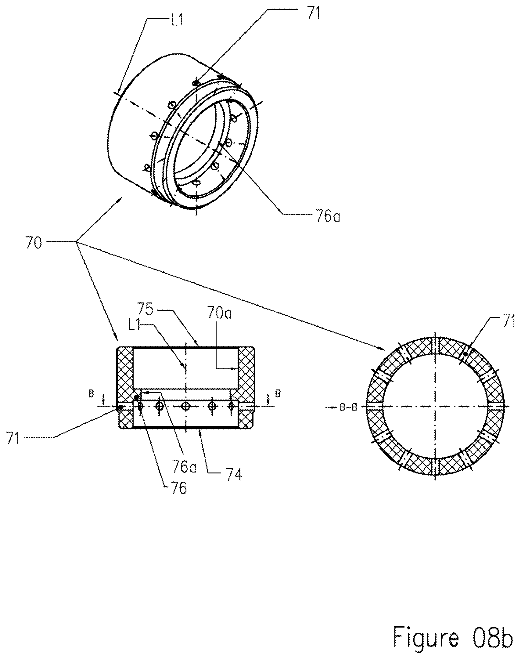
D00025

D00026
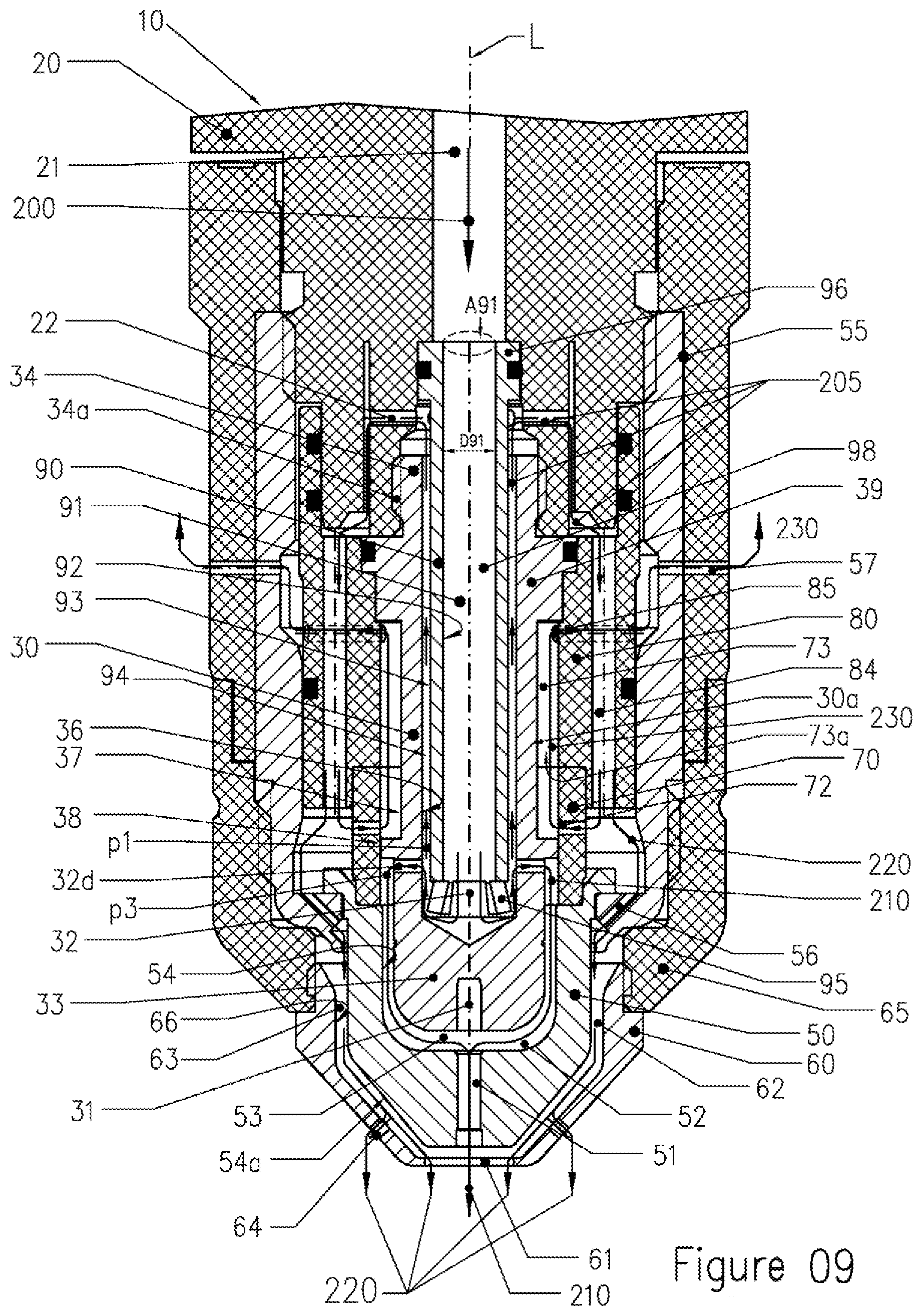
D00027
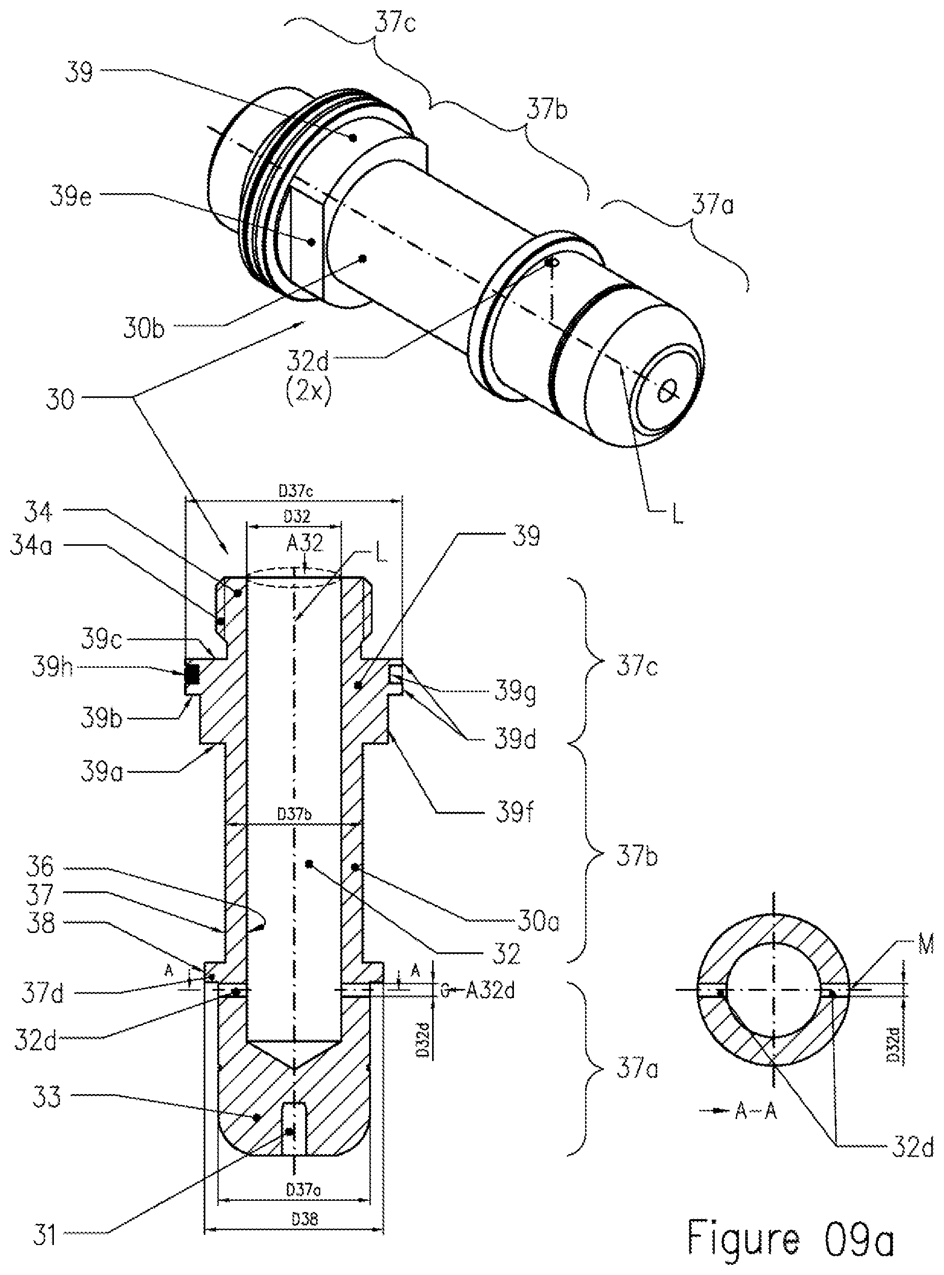
D00028
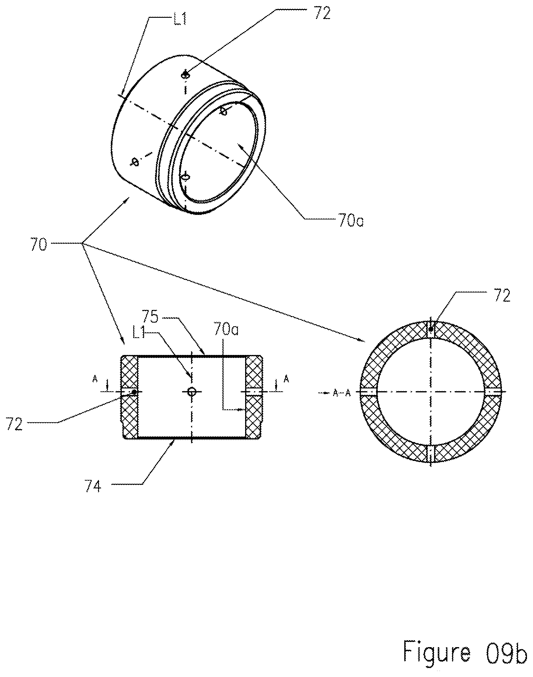
D00029
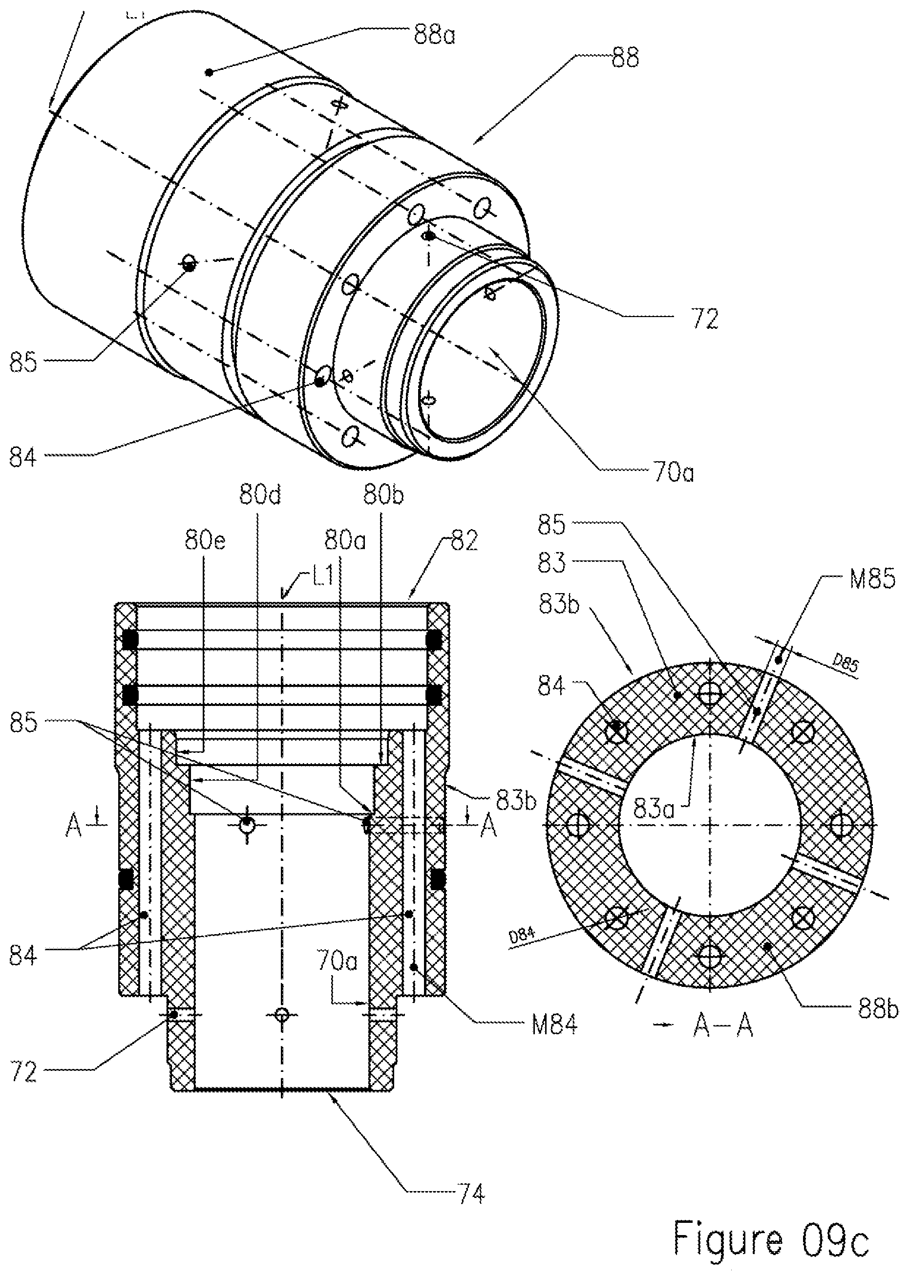
D00030

D00031

D00032

D00033

D00034

D00035

D00036

D00037

D00038
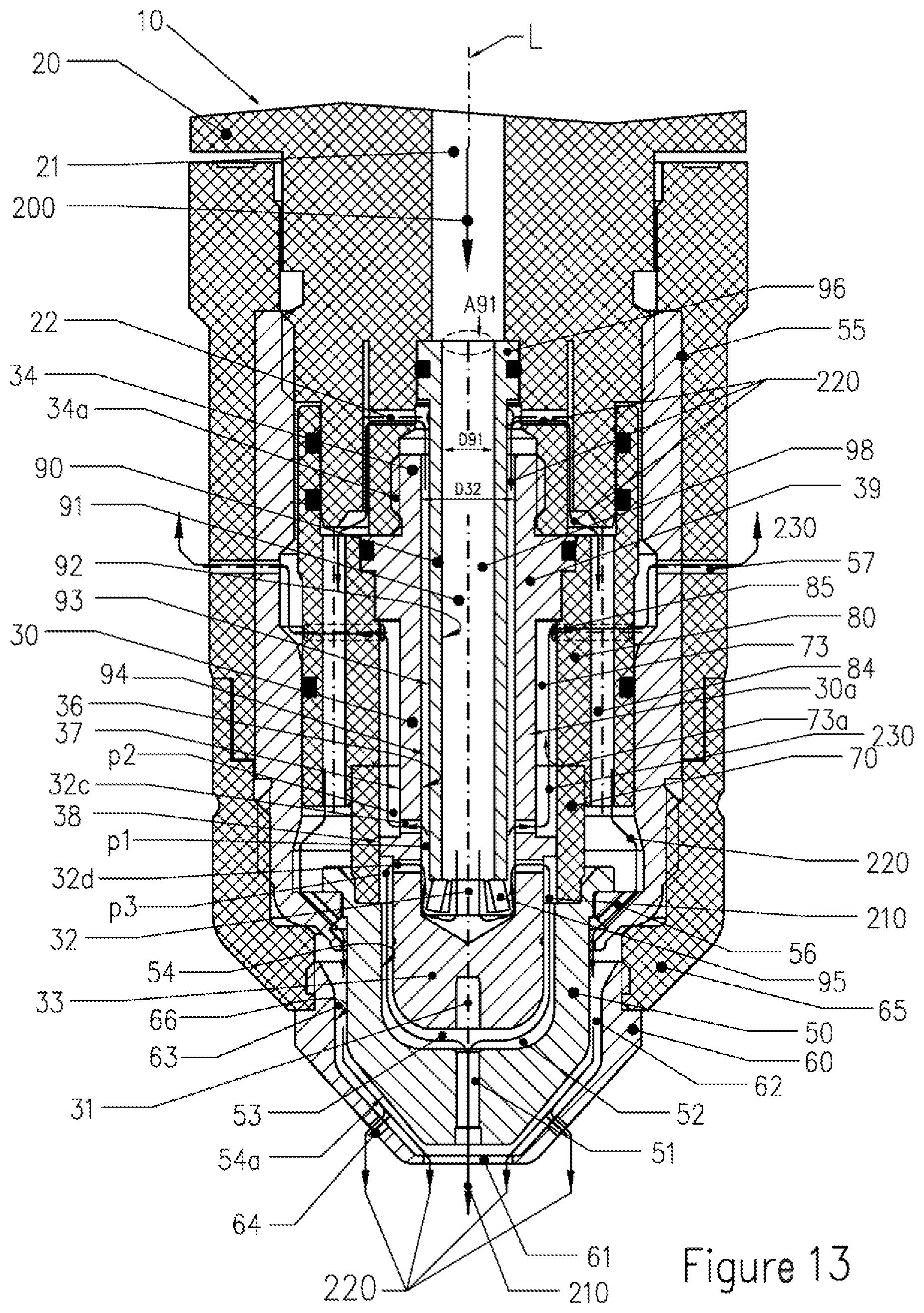
D00039

D00040

D00041

D00042
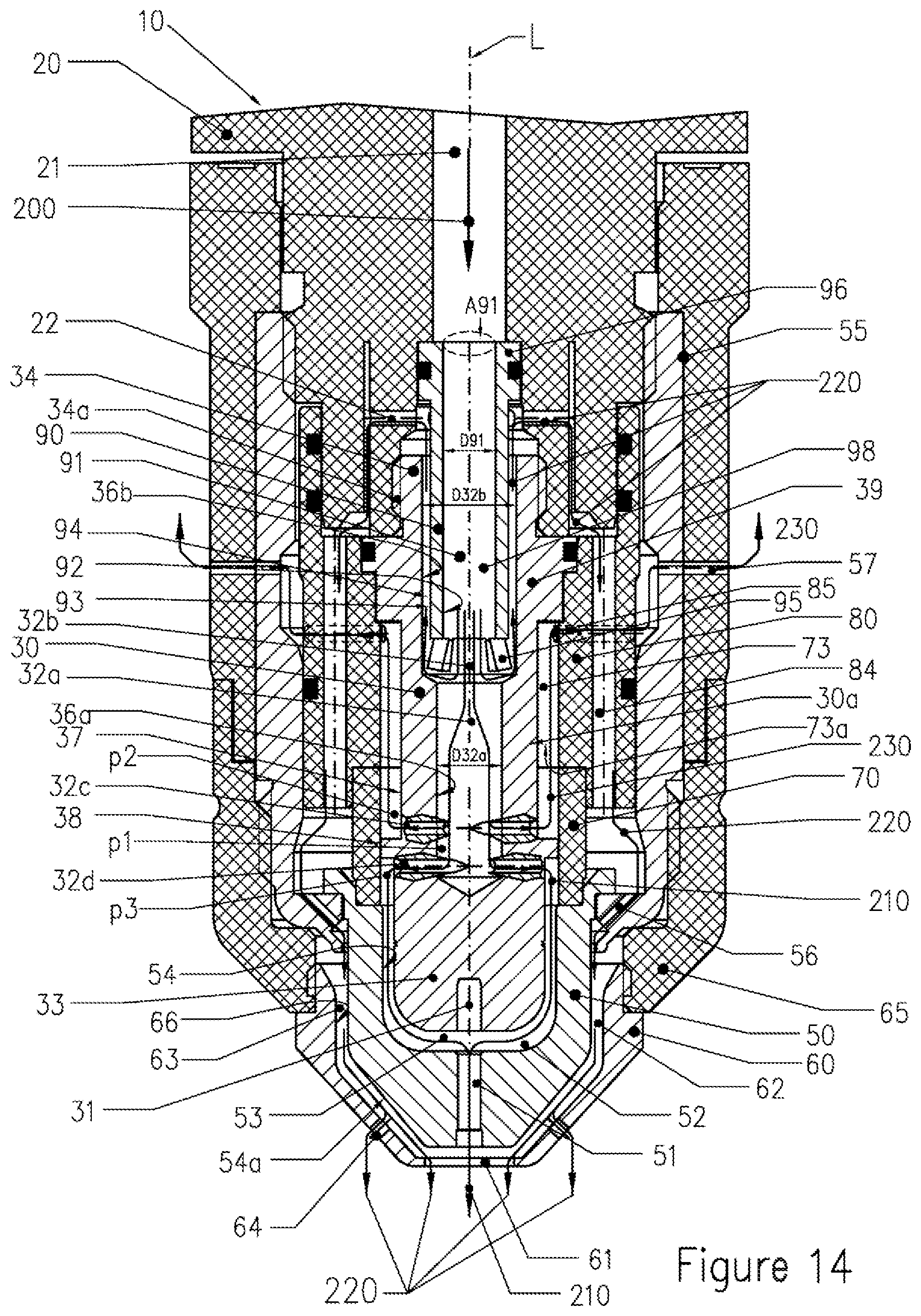
D00043

D00044

D00045

D00046

D00047

D00048
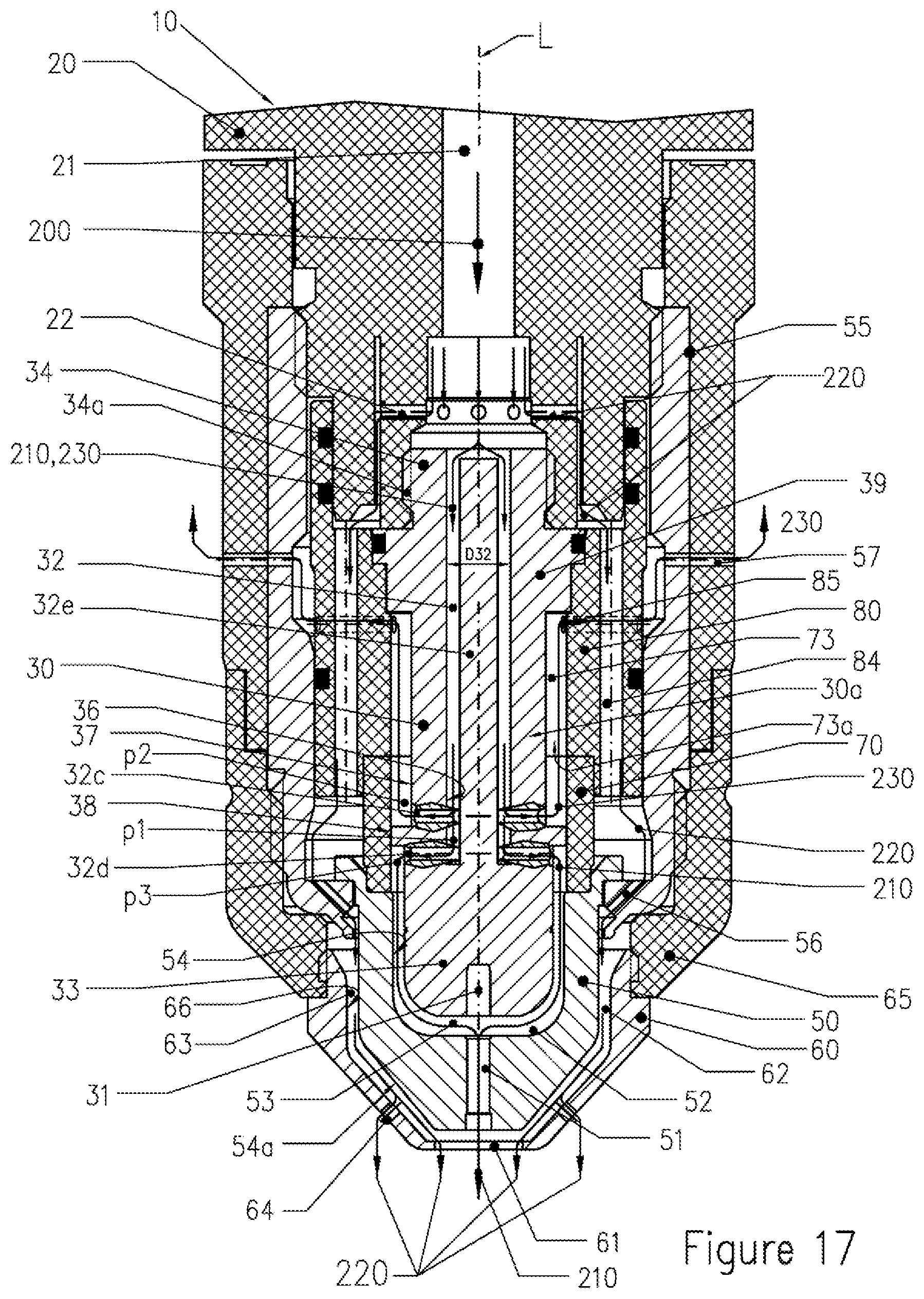
D00049
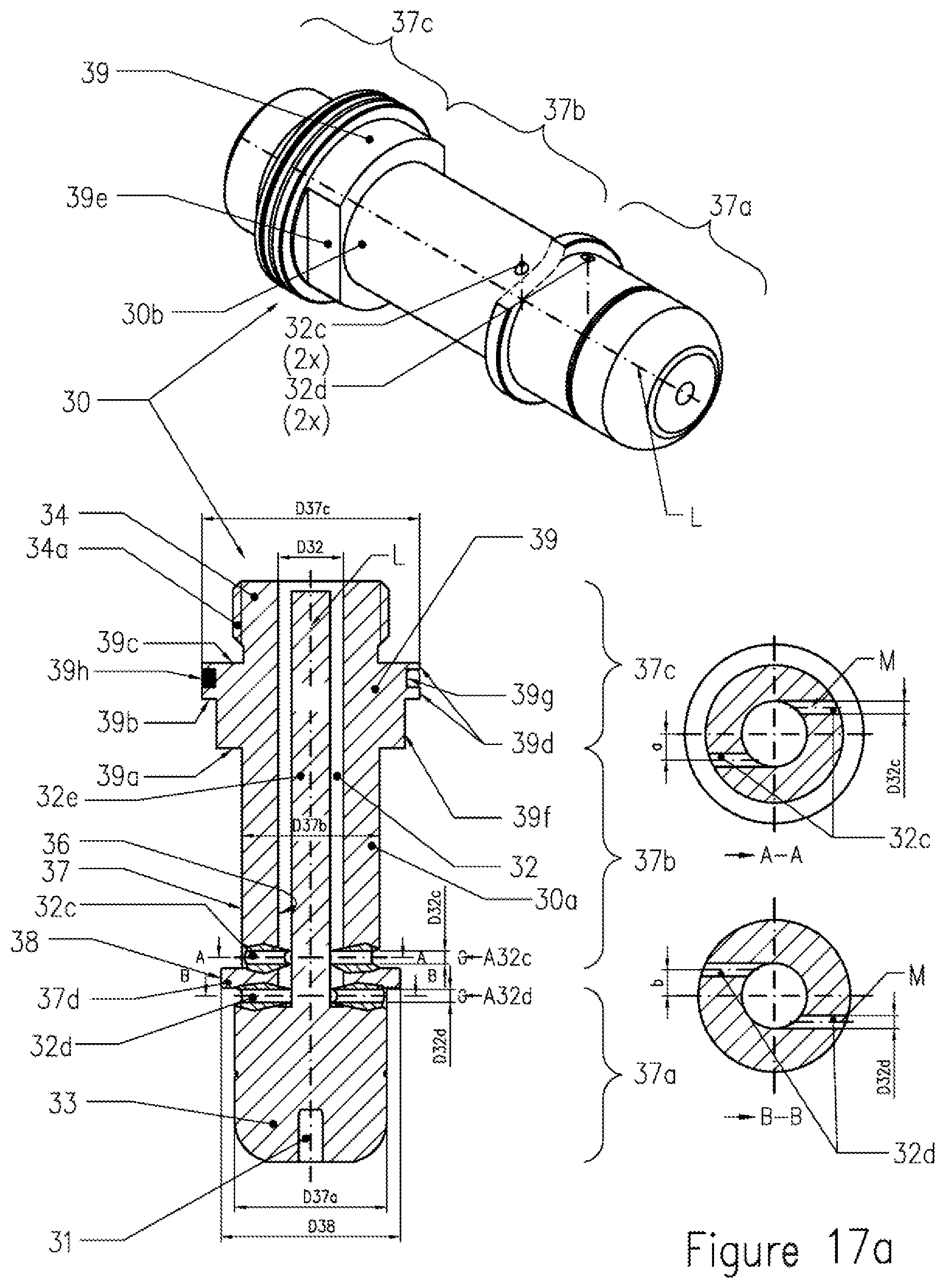
D00050

D00051

D00052

D00053

D00054

D00055

D00056

D00057

D00058

D00059

D00060

D00061

D00062

D00063

D00064

D00065

D00066

D00067

D00068
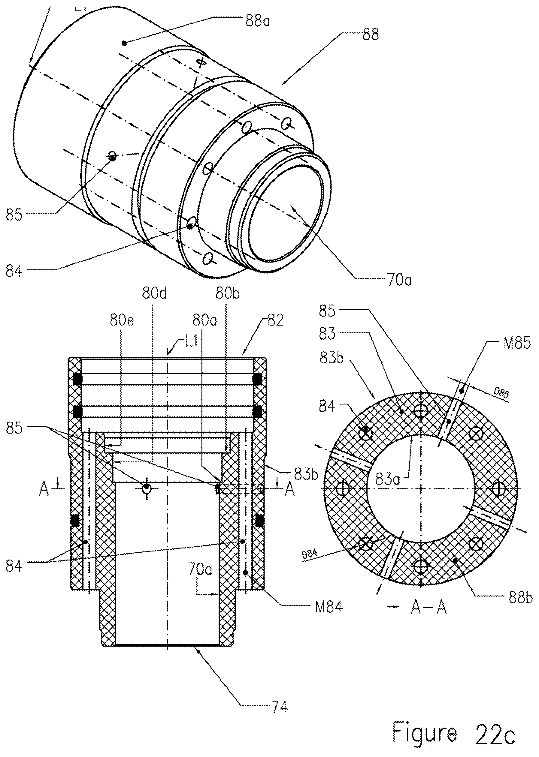
XML
uspto.report is an independent third-party trademark research tool that is not affiliated, endorsed, or sponsored by the United States Patent and Trademark Office (USPTO) or any other governmental organization. The information provided by uspto.report is based on publicly available data at the time of writing and is intended for informational purposes only.
While we strive to provide accurate and up-to-date information, we do not guarantee the accuracy, completeness, reliability, or suitability of the information displayed on this site. The use of this site is at your own risk. Any reliance you place on such information is therefore strictly at your own risk.
All official trademark data, including owner information, should be verified by visiting the official USPTO website at www.uspto.gov. This site is not intended to replace professional legal advice and should not be used as a substitute for consulting with a legal professional who is knowledgeable about trademark law.