Head-mounted Display Device And Display Control Method For Head-mounted Display Device
TAKEDA; Takashi ; et al.
U.S. patent application number 16/728315 was filed with the patent office on 2020-07-02 for head-mounted display device and display control method for head-mounted display device. This patent application is currently assigned to SEIKO EPSON CORPORATION. The applicant listed for this patent is SEIKO EPSON CORPORATION. Invention is credited to Toshiyuki KASAI, Toshiaki MIYAO, Masayuki TAKAGI, Takashi TAKEDA, Tokito YAMAGUCHI.
| Application Number | 20200213580 16/728315 |
| Document ID | / |
| Family ID | 71121884 |
| Filed Date | 2020-07-02 |


View All Diagrams
| United States Patent Application | 20200213580 |
| Kind Code | A1 |
| TAKEDA; Takashi ; et al. | July 2, 2020 |
HEAD-MOUNTED DISPLAY DEVICE AND DISPLAY CONTROL METHOD FOR HEAD-MOUNTED DISPLAY DEVICE
Abstract
In a left and right pair of a first display device and a second display device that perform repositionable display, mutually different display contents can be visually recognized as a first video image and a second video image. Further, a display control portion controls the display content in accordance with at least one of the first video image and the second video image.
| Inventors: | TAKEDA; Takashi; (Suwa-shi, JP) ; KASAI; Toshiyuki; (Okaya-shi, JP) ; TAKAGI; Masayuki; (Azumino-shi, JP) ; MIYAO; Toshiaki; (Matsumoto-shi, JP) ; YAMAGUCHI; Tokito; (Azumino-shi, JP) | ||||||||||
| Applicant: |
|
||||||||||
|---|---|---|---|---|---|---|---|---|---|---|---|
| Assignee: | SEIKO EPSON CORPORATION Tokyo JP |
||||||||||
| Family ID: | 71121884 | ||||||||||
| Appl. No.: | 16/728315 | ||||||||||
| Filed: | December 27, 2019 |
| Current U.S. Class: | 1/1 |
| Current CPC Class: | H04N 13/117 20180501; G02B 27/0172 20130101; G02B 2027/0134 20130101; H04N 13/366 20180501; H04N 13/344 20180501; G02B 2027/0178 20130101 |
| International Class: | H04N 13/344 20060101 H04N013/344; G02B 27/01 20060101 G02B027/01 |
Foreign Application Data
| Date | Code | Application Number |
|---|---|---|
| Dec 27, 2018 | JP | 2018-244289 |
Claims
1. A head-mounted display device comprising: a left and right pair of a first display device and a second display device configured to repositionably display a first video image and a second video having mutually different display contents; and a display control unit configured to control the display content in accordance with at least one of a display position change of the first video image in the first display device and a display position change of the second video image in the second display device.
2. The head-mounted display device according to claim 1, wherein the first display device and the second display device change the display in a range over which the display position of the first video image and the display position of the second video image are separated from each other.
3. The head-mounted display device according to claim 2, wherein the first display device and the second display device display the first video image and the second video image in a display position outside of a front-facing position.
4. The head-mounted display device according to claim 1, wherein in a superimposed range of the display position of the first video image and the display position of the second video image, the display control unit blocks a video image section of one of the first video image and the second video image.
5. The head-mounted display device according to claim 1, wherein the first display device and the second display device use an organic EL as a light source of the first video image and the second video image.
6. The head-mounted display device according to claim 1, wherein the display control unit changes a control mode depending on a display content change mode that changes the display content in conjunction with a display position change of a video image, and a display content maintaining mode that maintains the display content regardless of the display position change.
7. The head-mounted display device according to claim 6, wherein the display control unit changes the display content to maintain a positional relationship of the display content in a virtual video image display space in the display content change mode.
8. The head-mounted display device according to claim 1, comprising: a posture detecting unit configured to detect a posture of the first display device and the second display device and to output a detection result to the display control unit.
9. The head-mounted display device according to claim 1, wherein the display control unit includes: a first display control unit configured to control the display content for the first video image; a second display control unit configured to control the display content for the second video image; and a display operation synchronizing unit configured to synchronize display operations between the first display control unit and the second display control unit.
10. The head mounted type display device according to claim 1, comprising: a posture adjustment mechanism configured to change, by adjusting a posture of at least one of the first display device and the second display device, a display position of a corresponding one of the first video image and the second video image.
11. A display control method for a head-mounted display device that includes a left and right pair of a first display device and a second display device that repositionably display a first video image and a second video having mutually different display contents, the method comprising: controlling the display content in accordance with at least one of a display position change of the first video image in the first display device and a display position change of the second video image in the second display device.
12-14. (canceled)
15. A non-transitory computer-readable storage medium, comprising a display control program for a head-mounted display device that includes a left and right pair of a first display device and a second display device that repositionably display a first video image and a second video image having mutually different display contents, the display control program comprising: controlling the display content in accordance with at least one of a display position change of the first video image in the first display device and a display position change of the second video image in the second display device.
Description
[0001] The present application is based on, and claims priority from JP Application Serial Number 2018-244289, filed Dec. 27, 2018, the disclosure of which is hereby incorporated by reference herein in its entirety.
BACKGROUND
1. Technical Field
[0002] The present disclosure relates to a head-mounted display device represented by a head-mounted display, a display control method for a head-mounted display device, a display control system for a head-mounted display device, a display optical system for a head-mounted display device, a display control device for a head-mounted display device, and a display control program for a head-mounted display device.
2. Related Art
[0003] A head-mounted display device, such as a head-mounted display as described in JP-A-2018-54976, for example, is known in which a pair of left and right display devices are provided so as to allow stereoscopic video recognition. By providing first and second common display areas that perform image display of common content to left and right eyes, and an augmented display area that displays images unique to at least one of the left and right, various formats of image display are made possible while causing the image display to be perceived as a large image display. Note that the head-mounted display is also described as an HMD in the following.
[0004] However, in a configuration such as that exemplified in JP-A-2018-54976, for example, it is necessary to adjust the position of the left and right display with a high degree of precision so that the image being displayed to the left and right eyes is recognized as the common content. In this case, there is a possibility that it is difficult to respond to demands for maintaining optical performance, miniaturization, and the like, while increasing an amount of information displayed by individually displaying various pieces of information, for example.
SUMMARY
[0005] A head-mounted display apparatus according to an aspect of the present disclosure includes: a pair of left and right first display devices and a second display device for reversibly displaying a first video image and a second video image of different display contents. A display control unit configured to control the display content in accordance with the change in the display position of the first video image on the first display device and the display position change of the second video image on the second display device.
BRIEF DESCRIPTION OF THE DRAWINGS
[0006] FIG. 1 is a schematic perspective view illustrating a head-mounted display device according to a first embodiment.
[0007] FIG. 2 is a block diagram for describing a control mechanism of the head-mounted display device.
[0008] FIG. 3 is a conceptual diagram of an entire video region recognized by stereoscopic vision.
[0009] FIG. 4 is a conceptual diagram of the entire video region recognized by stereoscopic vision.
[0010] FIG. 5 is a conceptual diagram illustrating an example of image processing with respect to position changes of a first video image and a second video image.
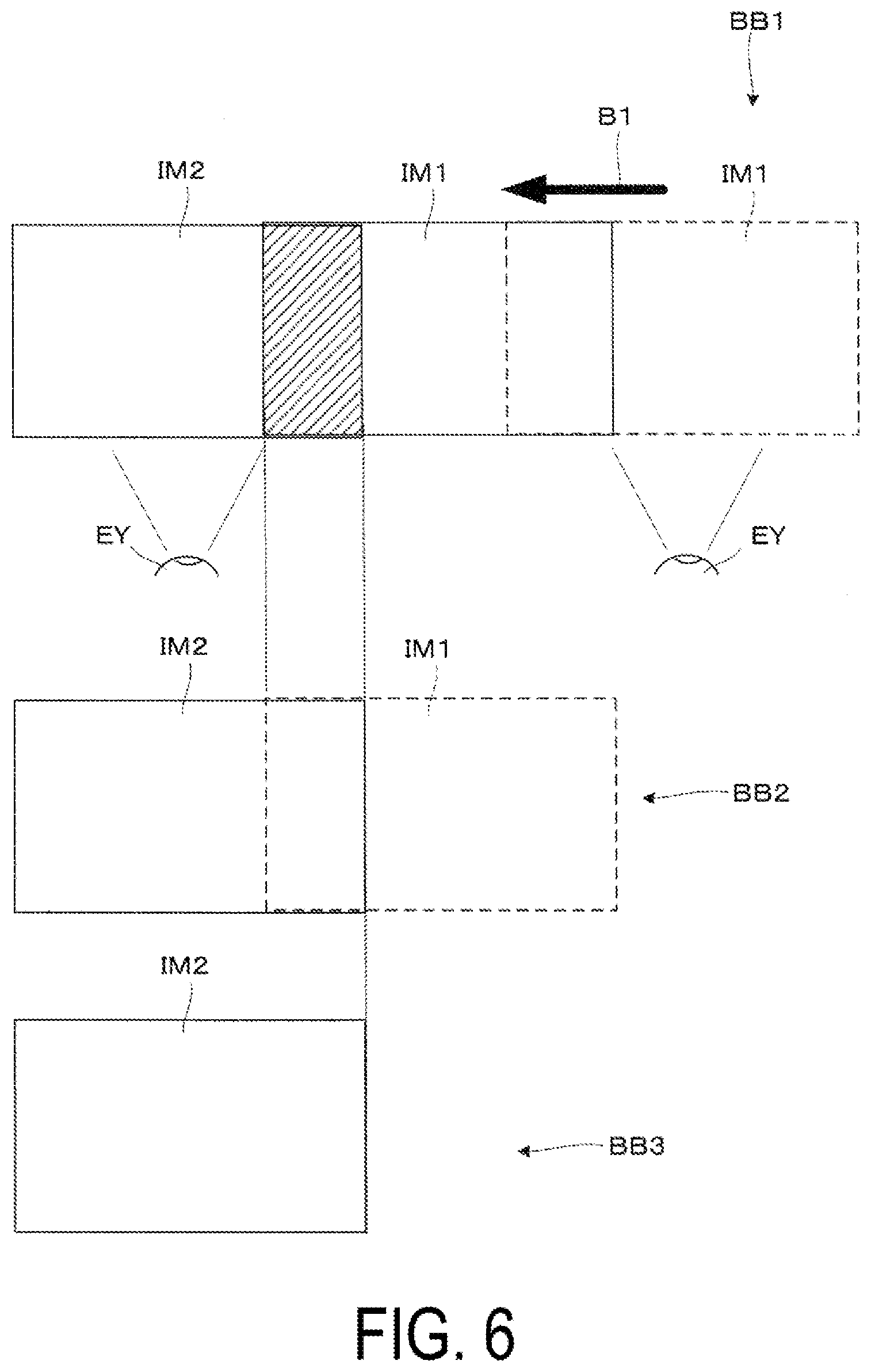
[0011] FIG. 6 is a conceptual diagram illustrating another example of the image processing with respect to position changes of the first video image and the second video image.
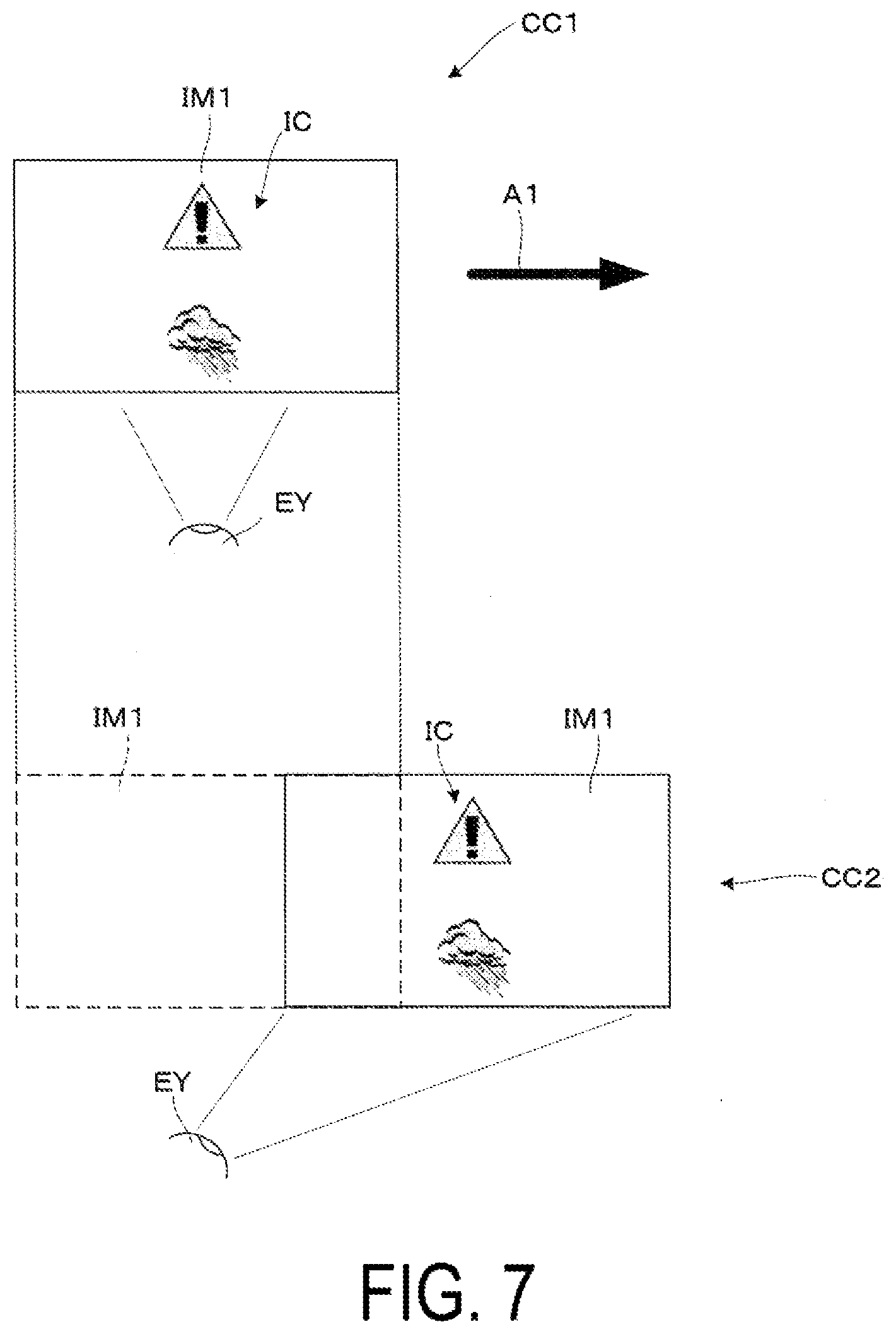
[0012] FIG. 7 is a conceptual diagram illustrating an example of operations in a display content maintaining mode in which display content is maintained even when a display position is changed.
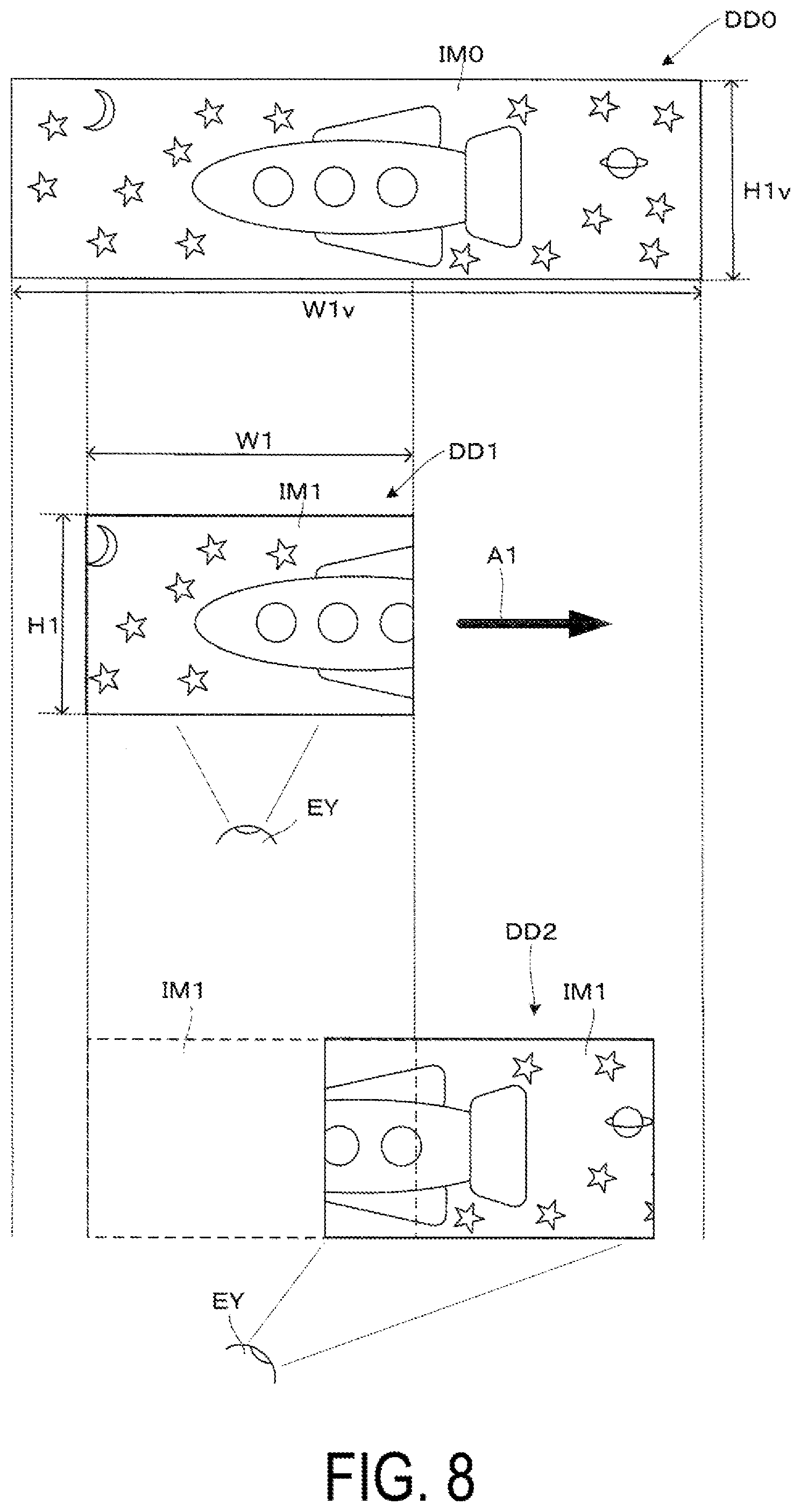
[0013] FIG. 8 is a conceptual diagram illustrating an example of operations in a display content change mode in which display content is changed in conjunction with a display position change of a video image.
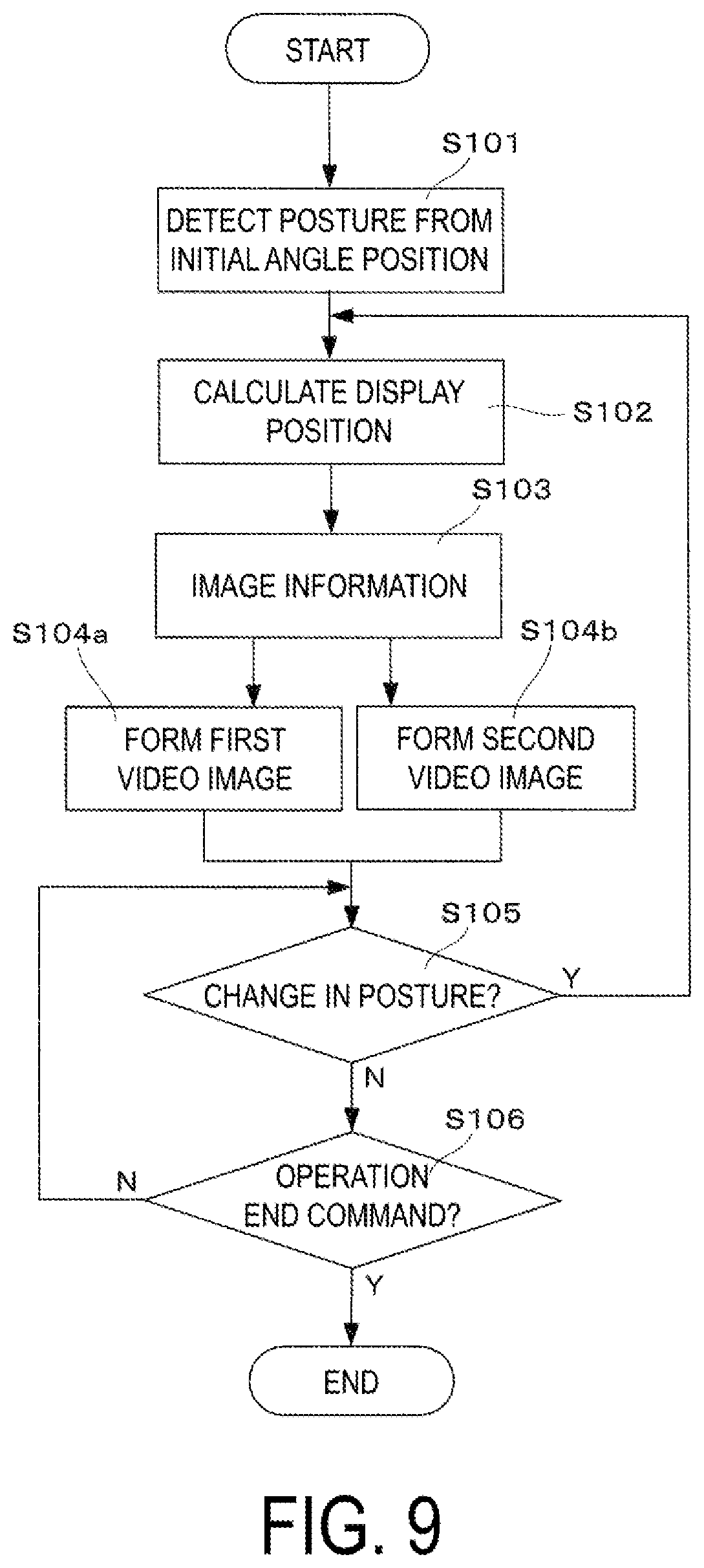
[0014] FIG. 9 is a flowchart for describing an example of display control.
[0015] FIG. 10 is a schematic perspective view illustrating an example of a display optical system of the head-mounted display device.
[0016] FIG. 11 is a bottom surface view for describing a rotational movement of a first display device.
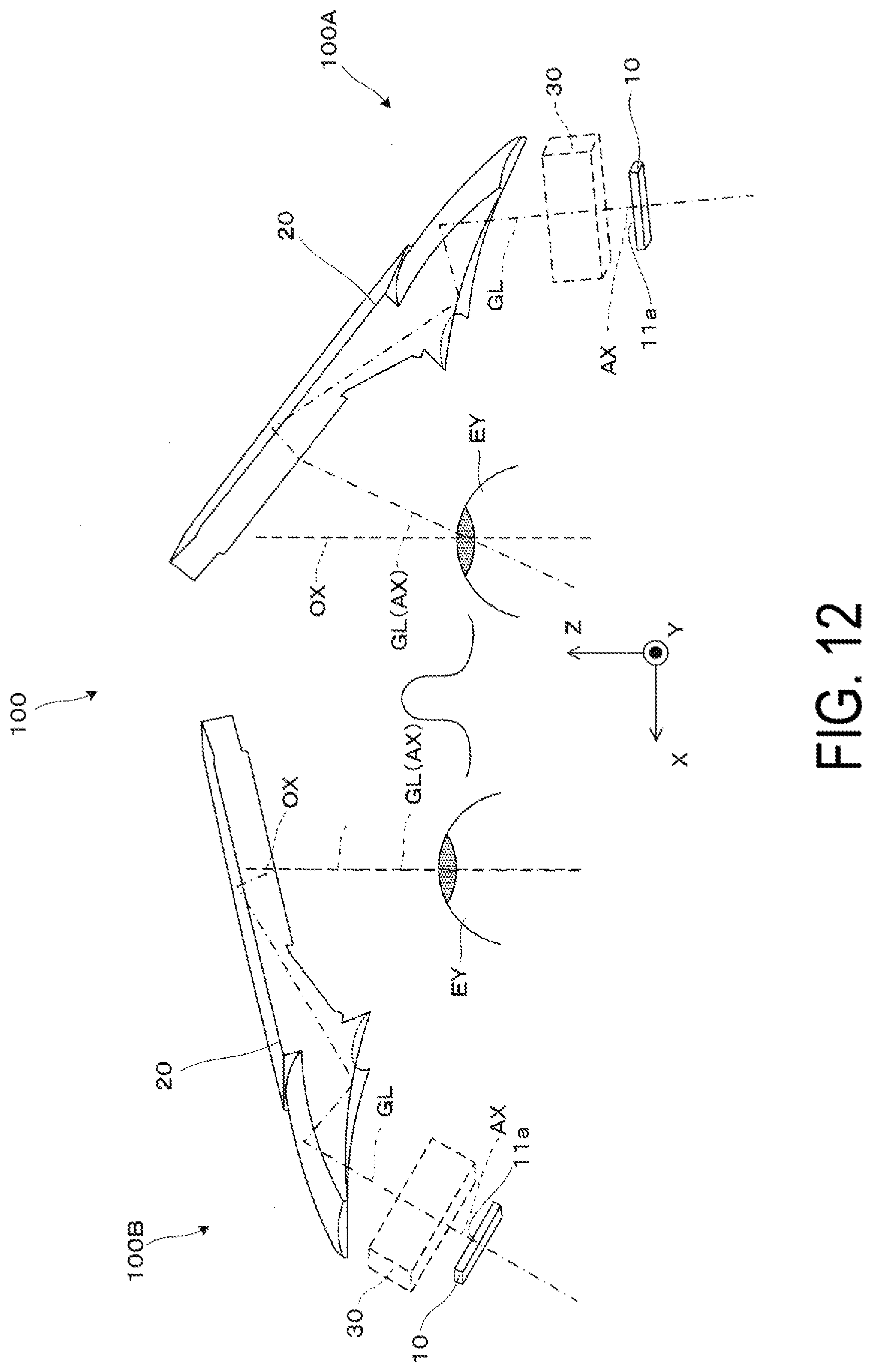
[0017] FIG. 12 is a conceptual diagram for describing the emission of image light to an observer by the first and a second display devices.
[0018] FIG. 13 is a conceptual diagram for describing changes in an emission angle of the image light to the observer by the first display device.
[0019] FIG. 14 is a block diagram for describing a control mechanism of the head-mounted display device according to a second embodiment.
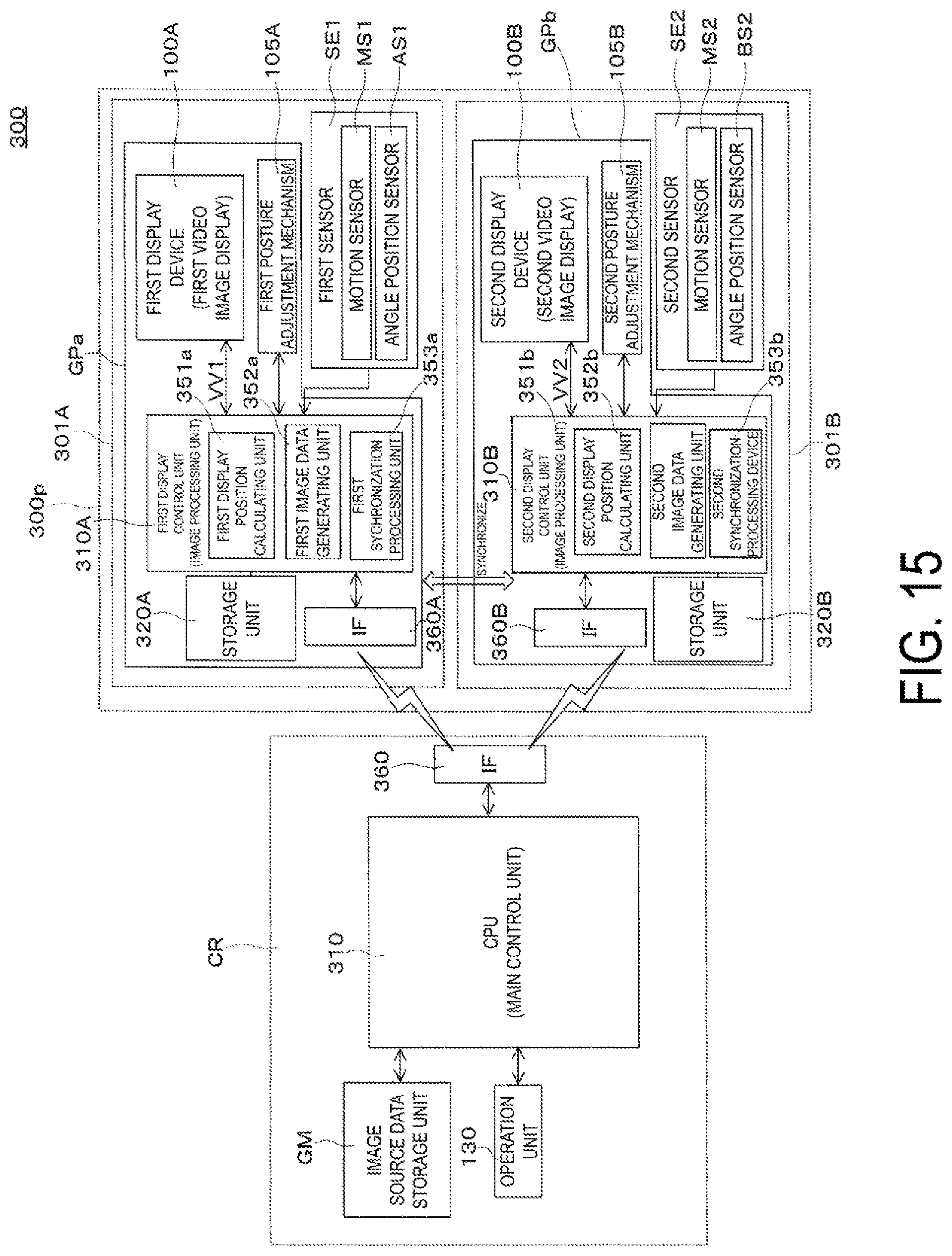
[0020] FIG. 15 is a block diagram for describing a control mechanism of the head-mounted display device according to a third embodiment.
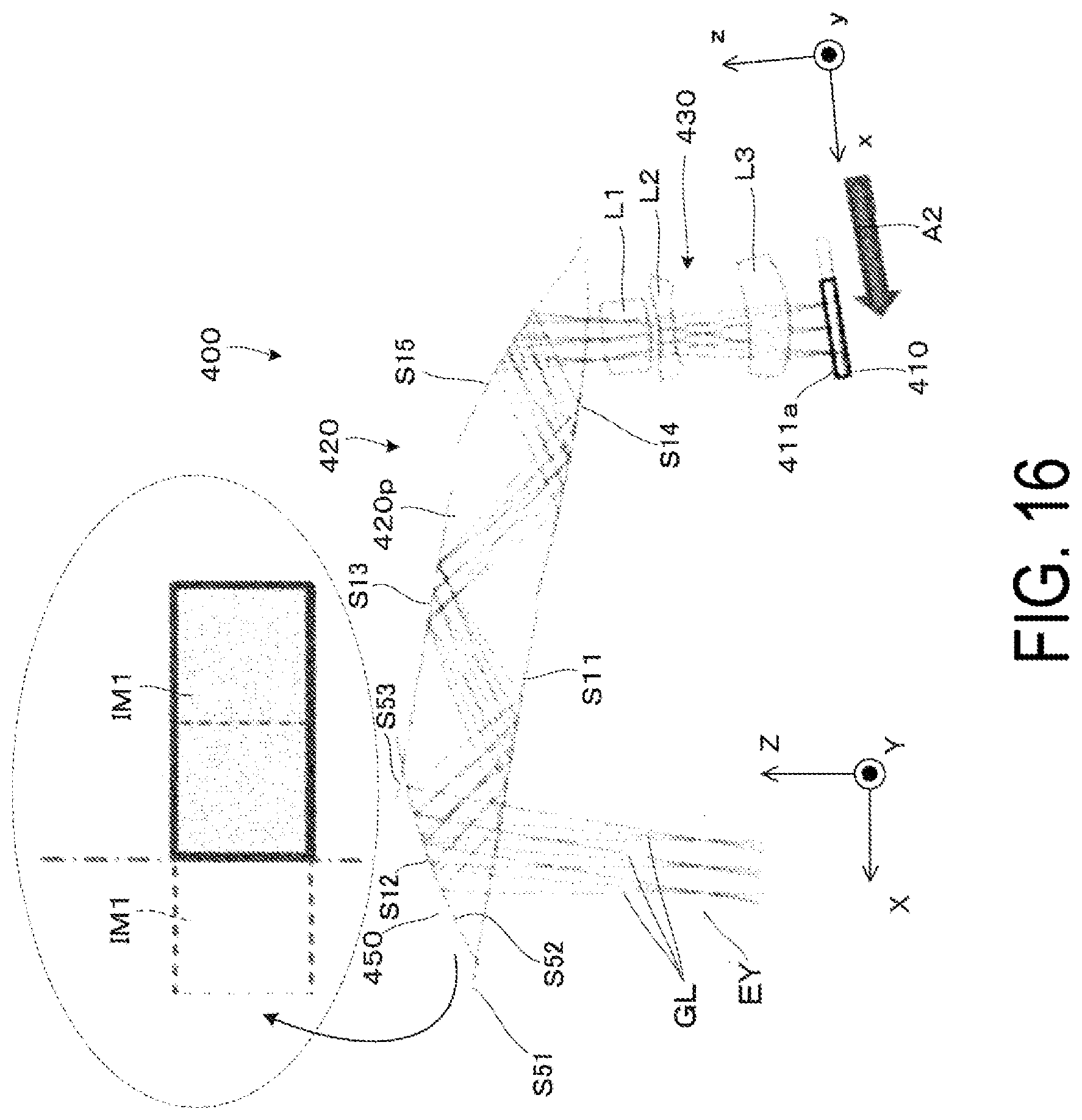
[0021] FIG. 16 is a schematic plan view illustrating a head-mounted display device according to a fourth embodiment.
[0022] FIG. 17 is a conceptual diagram illustrating a video region recognized by stereoscopic vision in the head-mounted display device according to a modified example.
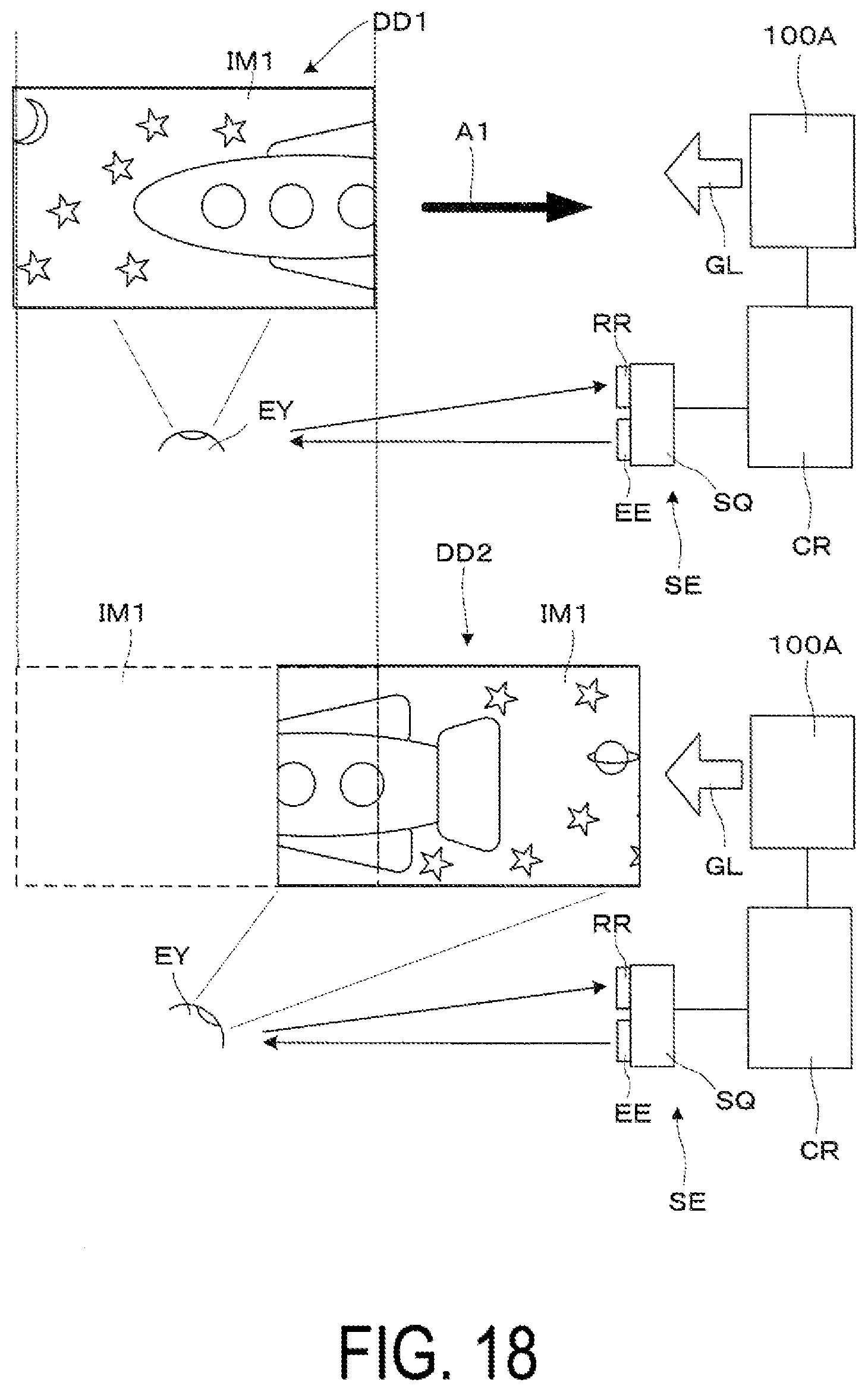
[0023] FIG. 18 is a conceptual diagram illustrating another example of operations performed in display position change.
DESCRIPTION OF EXEMPLARY EMBODIMENTS
First Embodiment
[0024] A head-mounted display device according to a first embodiment of the present disclosure will be described below in detail with reference to FIG. 1 and the like.
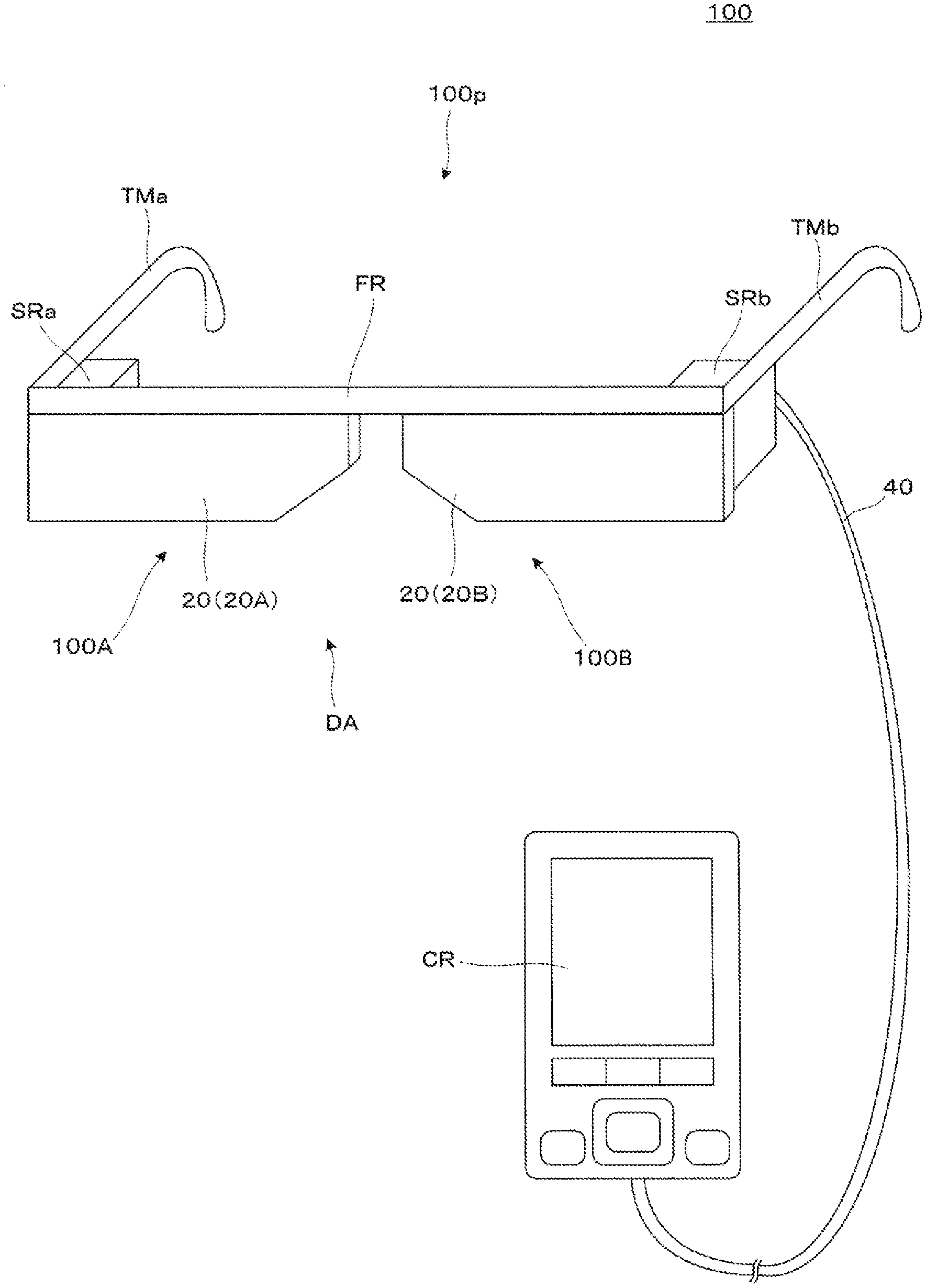
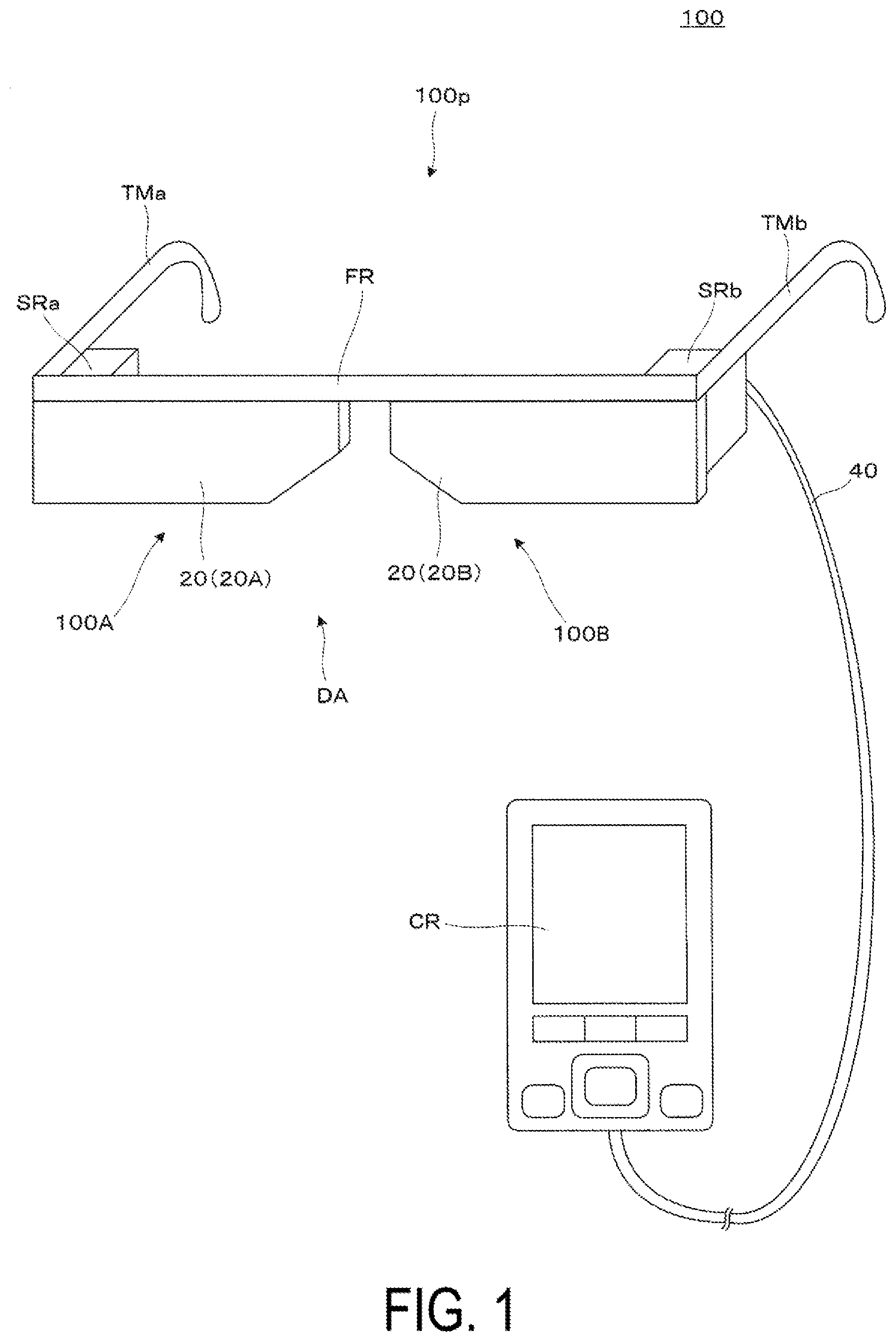
[0025] For example, as illustrated in FIG. 1 and the like, a head-mounted display device 100 of the present embodiment is a head-mounted display (HMD) having a visual appearance of eyeglasses, and is a virtual display device capable of causing an observer or user wearing the head-mounted display device 100 to visually recognize image light (image light) by a virtual image, and allowing the observer to visually recognize or observe an external world image in a see-through manner. The head-mounted display device 100 is provided with a first display device 100A and a second display device 100B.
[0026] Further, the head-mounted display device 100 includes an optical system, such as the first display device 100A or the like, outer packaging members (case members) SRa and SRb that house the optical system, or a frame portion FR that supports the optical system, and additionally, temple portions (temples) TMa and TMb or the like that are disposed on both left and right ends of the outer packaging members SRa and SRb or the frame portion FR and that extend to the rear. In this way, the head-mounted display device 100 can be worn in a similar manner to eyeglasses.
[0027] The head-mounted display device 100 is provided with a control device CR that configures a controller or the like as a UI for performing various control operations. In FIG. 1, of the head-mounted display device 100, respective portions on a mounting side, which is a configuration of the eyeglasses, are referred to as a main body 100p, and respective portions on a control side, such as the controller, are illustrated as the control device CR. In this case, the main body 100p configuring the entire mounting side is provided with an entire optical system for image formation in the head-mounted display device 100, and functions as a head-mounted display device display optical system. Note that the control device CR is connected to the main body 100p of the device having the eyeglasses shape by a cable (a connecting portion) 40.
[0028] Of the structural components of the head-mounted display device 100 in the drawings, first, the first display device 100A and the second display device 100B are portions that form a virtual image for a left eye and a right eye, respectively. In addition to a light-guiding device 20 that covers the front of the eyes of an observer in a see-through manner, the first display device 100A and the second display device 100B are respectively configured by image display devices (video elements) housed in the outer packaging members SRa and SRb, and an optical system for image formation, such as a projection lens and the like, thus enabling image display as a virtual image with respect to the corresponding left and right eyes. Furthermore, in the present embodiment, the first display device 100A and the second display device 100B include a posture adjustment mechanism that allows a position at which a video image is to be displayed to be changed. Note that a specific example of the head-mounted display device 100 that includes the first display device 100A and the second display device 100B and the like and that is provided with the above-described type of posture adjustment mechanism will be described later with reference to FIG. 10 and the like.
[0029] Further, in the present embodiment, the first display device 100A and the second display device 100B each function individually as a virtual display device, and in particular, can display individual content. Here, the video image displayed by the first display device 100A is referred to as a first video image, and the video image displayed by the second display device 100B is referred to as a second video image. In addition, in the present embodiment, the first display device 100A and the second display device 100B are combined to form a display mechanism DA. In other words, the display mechanism DA includes the pair of the left and right first display device 100A and second display device 100B that display the first video image and the second video image of mutually different display contents.
[0030] Hereinafter, control of the head-mounted display device 100 according to the present embodiment will be described with reference to a block diagram in FIG. 2. In particular, here, among the various control operations, control relating to the video display operation will be mainly described.
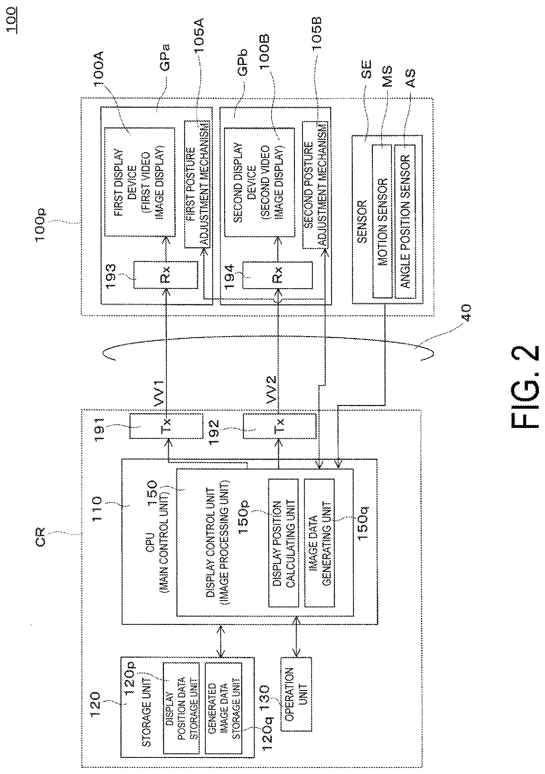
[0031] FIG. 2 is a block diagram illustrating an example of a configuration for describing the control of the head-mounted display device 100 illustrated in FIG. 1.
[0032] As illustrated here, various signals (in particular, video signals) are transmitted from the control device CR side to the main body 100p. Further, in addition to the first display device 100A and the second display device 100B, the main body 100p is provided with a first posture adjustment mechanism 105A and a second posture adjustment mechanism 105B, as posture adjustment mechanisms, that change display positions of the corresponding first video image and second video image by adjusting the postures of the first display device 100A and the second display device 100B. Furthermore, various types of sensor SE and the like are provided inside devices of the main body 100p. It is conceivable that the various sensors SE include, for example, a motion sensor MS that is configured by a gyro sensor, a camera, or the like, and that allows the posture, movement, and the like of the observer to be detected, by detecting acceleration, angular acceleration, and a rotation angle of the first posture adjustment mechanism 105A and the second posture adjustment mechanism 105B, and the like, and an angle position sensor AS or the like that detects a rotation angle as a detection of the posture adjustment of the first and second posture adjustment mechanisms 105A and 105B. Various signals for the various types of information acquired from these sensors are transmitted to the control device CR from the main body 100p side.
[0033] Hereinafter, the configuration of the control device CR will be described in detail. First, of the head-mounted display device 100, the control device CR includes a CPU (main control unit) 110, a storage unit 120, an operation unit 130, and transmission units (Tx) 191 and 192.
[0034] The storage unit 120 is configured by a ROM, a RAM, and the like, and various computer programs and types of data are stored in the storage unit 120.
[0035] By reading and executing a computer program or data from the storage unit 120, the CPU 110 functions as a display control unit (image processing unit) 150 configured by an operating system (OS) or the like, or as an input signal processing unit or the like. In other words, the CPU 110 functions as a main control unit responsible for the entire control of the head-mounted display device 100 by performing a variety of computational processing.
[0036] The operation unit 130 is an external input receiving device (input device) that is operated by the observer or the user, is configured by a determination key, a display switching key, a track pad, a brightness switching key, a direction key, a menu key, and the like, and acquires a signal corresponding to an operation input by the observer or the user.
[0037] The transmission units 191 and 192 respectively transmit various data, including video signals generated by the CPU 110, to the first and second display devices 100A and 100B configuring the main body 100p. In other words, the transmission units 191 and 192 function as transceivers for serial transfer between the control device CR and the first and second display devices 100A and 100B.
[0038] Here, for example, of the components described above, the display control unit 150 is provided with a display position calculating unit 150p that calculates a display position of the first video image and the second video image on the basis of information transmitted from the main body 100p as one of the various processes, and with an image data generating unit 150q that generates image data as image information to be output to the main body 100p on the basis of a calculation result of the display position calculating unit 150p as another of the various processes. Further, in order to store various pieces of information related to the processing by the display position calculating unit 150p and the image data generating unit 150q, a display position data storage unit 120p and a generated image data storage unit 120q for storing these pieces of information are provided in the storage unit 120.
[0039] Note that, in addition to the above, it is also conceivable to provide, on the main body 100p, a line-of-sight sensor or the like for detecting the line of sight of the observer, for example, or to provide various communication devices and interfaces for communicating with the outside, and further to provide various equipment for outputting sound, and the like.
[0040] The processing on the main body 100p side of the head-mounted display device 100 will be described below. First, reception units 193 and 194 function as receivers for the serial transfer between the control device CR and the first and second display devices 100A and 100B, and the first and second display devices 100A and 100B perform image formation on the basis of right eye image data and left eye image data respectively received by the reception units (Rx) 193 and 194.
[0041] Further, here, the first display device 100A, the first posture adjustment mechanism 105A, and the reception unit 193, which are components for forming an image for the right eye on the main body 100p side, are collectively referred to as a first image forming unit GPa. Similarly, the second display device 100B, the second posture adjustment mechanism 105B, and the receiver 194, which are components for forming an image for the left eye, are collectively referred to as a second image forming unit GPb. In other words, the first image forming unit GPa forms a first video image IM1 illustrated in FIG. 3 and the like on the basis of the image information for the right eye from the control device CR, and the second image forming unit GPb forms a second video image IM2 illustrated in FIG. 3 and the like on the basis of the image information for the left eye from the control device CR.
[0042] In the configuration as described above, in a case in which the CPU 110 functions as the display control unit (or the image processing unit) 150, the display control unit 150 generates image data (right eye image data and left eye image data) on the basis of the image signal included in the content or the like for each video image. The generated signals are supplied to the first and second display devices 100A and 100B that configure the main body 100p, as video signals for controlling the display operation of the head-mounted display device 100. In other words, the CPU 110 controls the image display by transmitting the generated video signals to the reception units 193 and 194 via the transmission units 191 and 192, respectively.
[0043] Here, as the video signals (image data) to be transmitted, the display control unit 150 generates image information VV1 relating to the first video image IM1 for the first display device 100A and image information VV2 relating to the second video image IM2 for the second display device 100B. In other words, the display control unit 150 transmits data information of different contents, through the image display allowing visual recognition by the right eye and the image display allowing visual recognition by the left eye. Furthermore, in this case, the display control unit 150 forms the image information VV1 and VV2 while taking into account information relating to the posture adjustment (or a state) of the first and second display devices 100A and 100B on the basis of a state of the first and second posture adjustment mechanisms 105A and 105B, which is the rotation angle of the first and second posture adjustment mechanisms 105A and 105B, using the motion sensor MS and the angle angle position sensor AS provided as the sensors SE. In other words, the sensors SE are posture detecting units that detect the posture of the first display device 100A and the second display device 100B and output the detection result to the display control unit 150.
[0044] As described above, for example, as illustrated in an upper row .gamma. in FIG. 3, of the first video image IM1 and the second video image IM2 formed by the first and second display devices 100A and 100B, respectively, the first video image IM1 formed by the first display device 100A can be moved in a direction indicated by an arrow A1 to allow the first video image IM1 to be visually recognized as an image displaced to the outside, that is to the right side, as illustrated in a lower row 6 in FIG. 3. Note that in this case, as illustrated in FIG. 4, the second video image IM2 formed by the second display device 100B can be caused to be recognized as being directly in front, and the first video image IM1 formed by the first display device 100A can be caused to be recognized as being in a position displaced from the front to the right side. In this case, even if the display contents are mutually different for the right and left eyes, the images can be recognized in each of the right eye and the left eye, the images can be individually recognized without any fusion between them, and an amount of information can be increased.
[0045] In addition, in this case, by manually or automatically rotatingly moving the first display device 100A and the second display device 100B individually, the image required by the observer can be sifted and selected. For example, by rotating the video image for which the display position is to be changed by an angle that is equal to or greater than half the angle of view of the video image, both the images (both video images) can be sufficiently separated, and the images can be prevented from being recognized in a superimposed position. For example, in a case in which the angle of view (FOV) of the video image is 50.degree., by setting a range over which the display position can be changed to be 25.degree. or greater, the left and right images can be sufficiently separated even when the angle of view is wide.
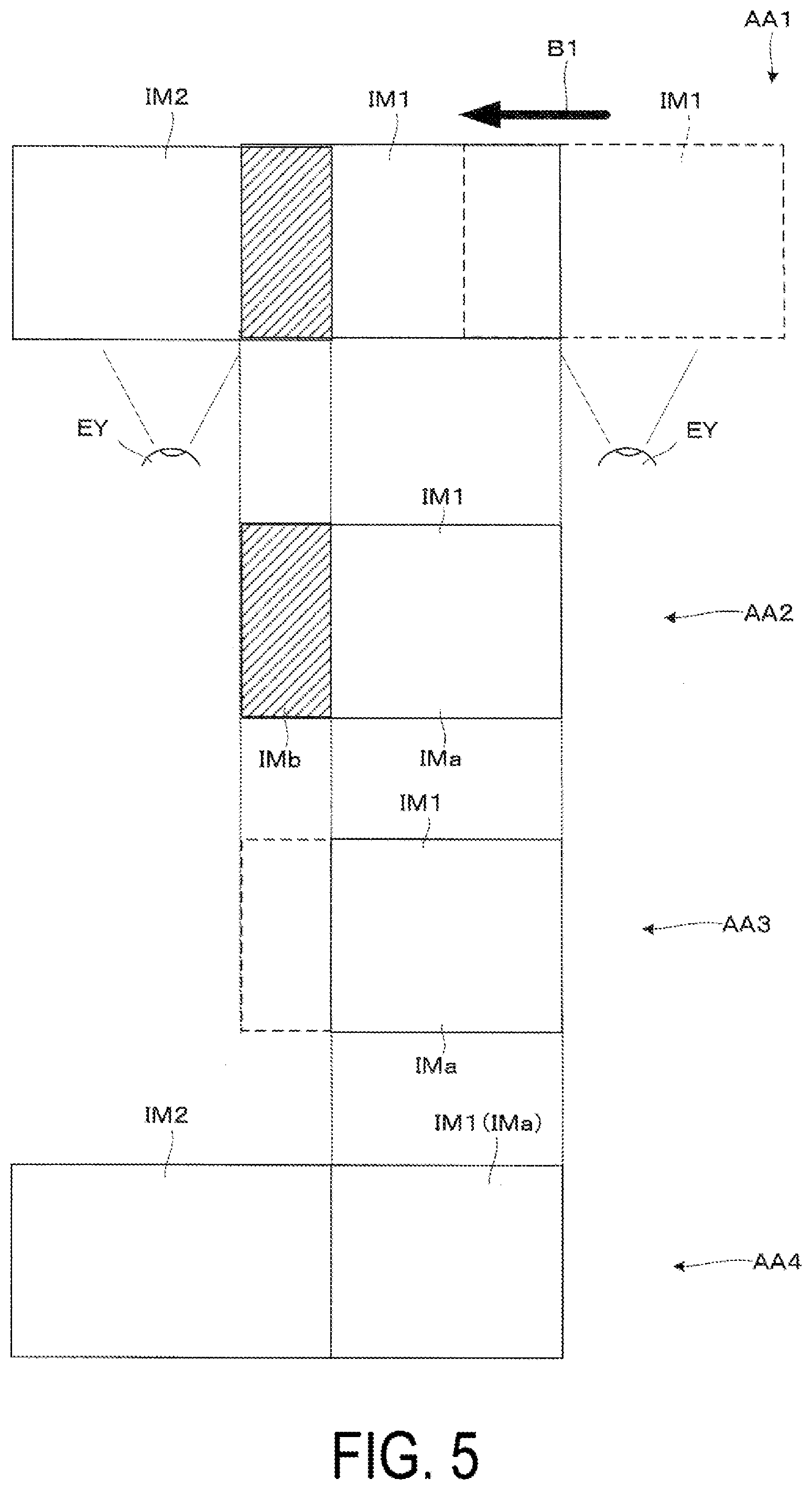
[0046] Hereinafter, with reference to a conceptual drawing illustrated in FIG. 5 and the like, several types of image processing for changing the display positions of the first video image IM1 and the second video image IM2 in modes other than those illustrated in FIG. 3 and FIG. 4 will be exemplified.
[0047] First, FIG. 5 illustrates a case in which the first video image IM1 is moved in a direction indicated by an arrow B1 from a position indicated by dashed lines to a position indicated by solid lines, as illustrated in a first step AA1, and is moved toward the inner side, that is the left side, so as to be moved closer to the second video image IM2. In this case, as illustrated by a hatched region, a portion of the first video image IM1 visually recognized by a right eye EY and a portion of the second video image IM2 visually recognized by the left eye EY are recognized as images in a superimposed position (a superimposed range). To avoid such a situation, first, as illustrated in a second step AA2, the first video image IM1 is divided into a non-superimposed video portion IMa that is not superimposed on the second video image IM2, and a superimposed video portion IMb that is superimposed thereon. As illustrated in a third step AA3, the new video image IM1 is generated by deleting the superimposed video portion IMb and leaving only the non-superimposed video portion IMa. As illustrated in a fourth step (final step) AA4, the second video image IM2 and the first video image IM1 are displayed in this state. In other words, the display control unit 150 performs various processes to block the video portion of the first video image IM1, among the first video image IM1 and the second video image IM2, in the superimposed video portion IMb, which is the superimposed range of the display position of the first video image IM1 and the display position of the second video image IM2. Note that in this case, the second video image IM2 formed by the second display device 100B is caused to be recognized as being directly in front, and the first video image IM1 formed by the first display device 100A is caused to be recognized as being in a position displaced from the front position to the right.
[0048] Note that the processing method described above is an example, and it is also conceivable to delete a portion of the second video image IM2, as opposed to the case described above. In addition, the side to be deleted may be determined on the basis of various settings such as, for example, which is the dominant eye of the observer, and which side is the main image. Furthermore, in the processes described above, a certain margin may be imparted to the range to be deleted. This is because, for example, when the display content in the left and right images is different, it is not necessary to adjust the image to the left and right eyes in pixel units in order to cause an image common to both the left and right eyes to be visually recognized.
[0049] Further, as illustrated in another mode in FIG. 6, it is also conceivable to perform various processes so as to block the entirety of one of the first video image IM1 and the second video image IM2. In other words, a mode may be adopted in which, as in the case of the first step AA1 in FIG. 5, when a location occurs in a first step BB1 that is recognized as an image in the superimposed position (the superimposed range), as illustrated in a second step BB2, the entirety of the first video image IM1 is deleted, and, as illustrated in a third step BB3 (a final step), only the second video image IM2 is displayed.
[0050] Note that, in a case of the mode in which one of the images is deleted, as described above, it is conceivable to adopt an organic EL as a light source of the video image light for forming the first video image IM1 and the second video image IM2 in the first and second display devices 100A and 100B. By using the organic EL, black floating of the portion to be blocked can be avoided, and an appropriate image can be deleted.
[0051] Further, for example, the content to be displayed may be changed in accordance with the mode to be used for the video image. Specifically, a control mode may be changed according to a display content change mode for changing the display content in conjunction with the display position change of the video image, and to a display content maintaining mode for maintaining the display content regardless of the display position change. FIG. 7 is a conceptual diagram illustrating an example of operations in the display content maintaining mode in which the display content is maintained even when the display position is changed, and FIG. 8 is a conceptual diagram illustrating an example of operations in the di
D00000
D00001
D00002
D00003
D00004
D00005
D00006
D00007
D00008
D00009
D00010
D00011
D00012
D00013

D00014

D00015
D00016
D00017

D00018
XML
uspto.report is an independent third-party trademark research tool that is not affiliated, endorsed, or sponsored by the United States Patent and Trademark Office (USPTO) or any other governmental organization. The information provided by uspto.report is based on publicly available data at the time of writing and is intended for informational purposes only.
While we strive to provide accurate and up-to-date information, we do not guarantee the accuracy, completeness, reliability, or suitability of the information displayed on this site. The use of this site is at your own risk. Any reliance you place on such information is therefore strictly at your own risk.
All official trademark data, including owner information, should be verified by visiting the official USPTO website at www.uspto.gov. This site is not intended to replace professional legal advice and should not be used as a substitute for consulting with a legal professional who is knowledgeable about trademark law.