Method And Apparatus For Providing Vendor Remote Support And Management
NGO; Huey Jiun ; et al.
U.S. patent application number 16/745440 was filed with the patent office on 2020-07-02 for method and apparatus for providing vendor remote support and management. The applicant listed for this patent is BeyondTrust Corporation. Invention is credited to Nathan Whiteford CROMER, David William DURHAM, Nathan Joel MCNEILL, Huey Jiun NGO.
| Application Number | 20200213327 16/745440 |
| Document ID | / |
| Family ID | 42827247 |
| Filed Date | 2020-07-02 |


View All Diagrams
| United States Patent Application | 20200213327 |
| Kind Code | A1 |
| NGO; Huey Jiun ; et al. | July 2, 2020 |
METHOD AND APPARATUS FOR PROVIDING VENDOR REMOTE SUPPORT AND MANAGEMENT
Abstract
An approach is provided for establishing a vendor portal configured to provide remote control and management of one or more devices of a customer by a plurality of vendors. The device can then be remotely controlled, accessed, or operated upon via the vendor portal.
| Inventors: | NGO; Huey Jiun; (Flowood, MS) ; MCNEILL; Nathan Joel; (Ridgeland, MS) ; DURHAM; David William; (Raymond, MS) ; CROMER; Nathan Whiteford; (Brandon, MS) | ||||||||||
| Applicant: |
|
||||||||||
|---|---|---|---|---|---|---|---|---|---|---|---|
| Family ID: | 42827247 | ||||||||||
| Appl. No.: | 16/745440 | ||||||||||
| Filed: | January 17, 2020 |
Related U.S. Patent Documents
| Application Number | Filing Date | Patent Number | ||
|---|---|---|---|---|
| 15489294 | Apr 17, 2017 | 10554668 | ||
| 16745440 | ||||
| 12755347 | Apr 6, 2010 | |||
| 15489294 | ||||
| 61166962 | Apr 6, 2009 | |||
| Current U.S. Class: | 1/1 |
| Current CPC Class: | H04L 67/025 20130101; H04L 63/0218 20130101; G06Q 30/06 20130101; H04L 63/105 20130101; H04L 41/28 20130101; H04L 67/34 20130101; H04L 41/18 20130101; G06F 21/6218 20130101; H04L 63/20 20130101; H04L 41/022 20130101; H04L 63/029 20130101 |
| International Class: | H04L 29/06 20060101 H04L029/06; H04L 12/24 20060101 H04L012/24; H04L 29/08 20060101 H04L029/08; G06F 21/62 20060101 G06F021/62 |
Claims
1. (canceled)
2. A method comprising: establishing, by at least one computing device, an access session comprising a network connection between a support device and a customer device; receiving, by the at least one computing device, a first request from the support device for third-party assistance; transmitting, by the at least one computing device, a second request to a vendor device to provide the third-party assistance; providing, by the at least one computing device, a remote support application to the vendor device for download; and joining, by the at least one computing device and the remote support application, the vendor device into the access session between the support device and the customer device to provide support.
3. The method of claim 2, further comprising disconnecting, by the at least one computing device, the support device from the access session subsequent to the joining of the vendor device.
4. The method of claim 2, wherein the vendor device has view access to the access session.
5. The method of claim 2, wherein the vendor device is configured to execute the remote support application to join the access session.
6. The method of claim 2, wherein the customer device is not connected to the internet and the method further comprising providing, by the at least one computing device, a proxy for the customer device to access the internet.
7. The method of claim 2, wherein the remote support application is configured to be downloaded from a web interface.
8. The method of claim 2, wherein web browser based remote control of the customer device is provided by the vendor device via the remote support application.
9. A system comprising: a data store comprising identifying information for a plurality of customer devices; and at least one computing device in communication with the data store, the at least one computing device configured to: establish an access session comprising a network connection between a support device and a customer device of the plurality of customer devices; receive a first request from the support device for third-party assistance; transmit a second request to a vendor device to provide the third-party assistance; provide a remote support application to the vendor device for download; receive a connection request from the remote support application executed by the vendor device; and in response to the connection request, join the remote support application into the access session between the support device and the customer device to provide support.
10. The system of claim 9, further comprising at least one second computing device configured to: transmit a third request to a second vendor device to provide assistance to the vendor device; and establish a second access session comprising a second network connection between the second vendor device and the vendor device.
11. The system of claim 9, further comprising at least one second computing device configured to configure the at least one computing device to host a plurality of vendor portals including a particular vendor portal, wherein the connection request from the remote support application is received via the particular vendor portal.
12. The system of claim 9, wherein the connection request comprises a login request to a public Uniform Resource Locator (URL) corresponding to the at least one computing device.
13. The system of claim 9, wherein the at least one computing device is coupled to the customer device via a local-area network and the at least one computing device is coupled to the vendor device via a wide-area network.
14. The system of claim 9, wherein the at least one computing device is configured to provide the remote support application by pushing the remote support application, wherein the vendor device executes the remote support application and the remote support application connects back to the at least one computing device.
15. The system of claim 9, wherein the at least one computing device is further configured to: record a stream of a screen corresponding to the customer device during the access session; and store the stream of the screen in the data store.
16. A non-transitory computer-readable medium embodying a program that, when executed by at least one computing device, causes the at least one computing device to: establish an access session by connecting a support device with a customer device over a network; receive a first request from the access session for third-party assistance; transmit a second request to a vendor device to provide the third-party assistance; provide a remote support software to the vendor device for download; receive a connection request from the remote support software executed by the vendor device; and connect the remote support software into the access session to provide additional support.
17. The non-transitory computer-readable medium of claim 16, wherein the program further causes the at least one computing device to: transmit a third request to the vendor device to provide assistance for one of a plurality of customer devices, wherein the plurality of customer devices comprises the customer device; receive a connection request from the remote support software already installed on the vendor device; and establish a second access session by connecting the remote support software with the one of the plurality of customer devices.
18. The non-transitory computer-readable medium of claim 16, wherein the program further causes the at least one computing device to: record data relating to remote access by the vendor device; and perform an audit on the data recorded to determine compliance with a predetermined regulation.
19. The non-transitory computer-readable medium of claim 16, wherein the program further causes the at least one computing device to: assign a security policy to the vendor device; and control access rights and remote control permission of the vendor device based on the security policy.
20. The non-transitory computer-readable medium of claim 16, wherein a first firewall is positioned between the vendor device and the at least one computing device and a second firewall is positioned between the at least one computing device and the customer device.
21. The non-transitory computer-readable medium of claim 16, wherein the vendor device comprises a vendor representative system and a remote support and management appliance.
Description
RELATED APPLICATIONS
[0001] This application is a continuation of U.S. application Ser. No. 12/755,347 filed. Apr. 6, 2010, entitled "Method and Apparatus for Providing Vendor Remote Support and Management," which claims the benefit of the earlier filing date under 35 U.S.C. .sctn. 119(e) of U.S. Provisional Application Ser. No. 61/166,962 filed Apr. 6, 2009, entitled "Method and Apparatus for Providing Vendor Remote Support and Management," the entireties of which are incorporated by reference.
BACKGROUND OF THE INVENTION
[0002] Information Technology (IT) companies and departments who support their customers' computer systems are constantly challenged with the need to provide timely and cost-effective support to their customers. Remote support provides the means for IT professionals to remotely access and to control customers' computer systems. This eliminates the need for the IT professionals to travel on-site to fix a problem and the delays in response time.
[0003] Enterprises (or organizations) have many challenges when receiving support from a technology vendor via remote control or remote access technologies. When a system or application requires support and maintenance from a vendor, the vendor must be granted access in order to service the system or application effectively. Often, each technology vendor uses a different product, leaving the organization receiving support with little or no control over what remote access or remote control technologies are used. Most remote access and remote control tools support only "all or nothing" access, resulting in the vendor having much greater access than is required. Because of this, the organization receiving support does not have the ability to granularly control the permissions, access, and privileges granted to the technology vendor. Moreover, existing approaches do not record the activity of the technology vendor in the process of supporting the organization that is receiving support. In other words, support incidents do not have audit trails. This lack of control and lack of audit-ability undermines the compliance posture of the organization receiving support, thereby increasing the liability associated with receiving technology support from a vendor.
[0004] Based on the foregoing, there is a clear need for approaches that provide remote support and management involving multiple vendors.
BRIEF DESCRIPTION OF THE DRAWINGS
[0005] FIGS. 1A and 1B are, respectively, diagrams of a system and associated process for providing vendor remote support and management, according to certain embodiments;
[0006] FIGS. 2A and 2B are, respectively, diagrams of a system and associated process for providing vendor presence on a customer appliance, according to certain embodiments;
[0007] FIGS. 3A and 3B are, respectively, diagrams of a system and associated process for providing vendor presence on a customer appliance via a vendor's appliance, according to certain embodiments;
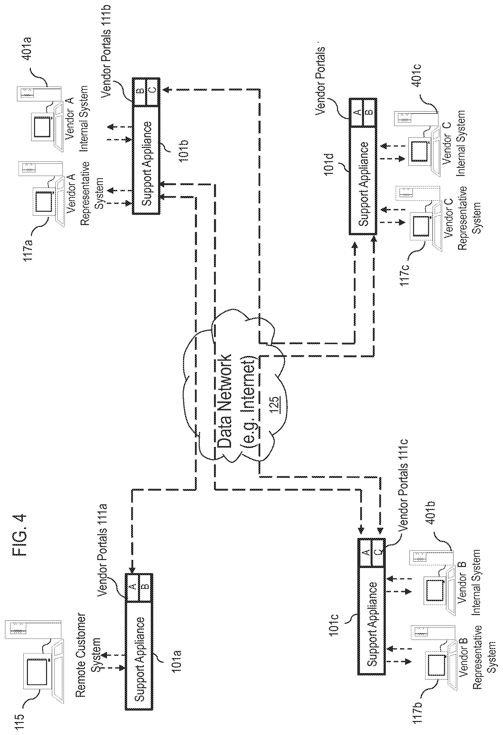
[0008] FIG. 4 is a diagram of a network of appliances with vendor presence, according to an exemplary embodiment;
[0009] FIGS. 5A and 5B are flowcharts of processes for establishing relationships between vendor and customer remote support systems, according to an exemplary embodiment;
[0010] FIGS. 6A-6C are diagrams of a system and associated processes for providing a vendor portal as an agent or a proxy, according to certain embodiments;
[0011] FIG. 7 is a diagram of a system capable of providing Push and Start technology within local area network (LAN) as well as remote networks, according to an exemplary embodiment;
[0012] FIG. 8 is a diagram of the software architecture of the communication system of FIG. 1, according to an exemplary embodiment;
[0013] FIG. 9 is an exemplary hardware architecture of a remote access and control appliance, according to an exemplary embodiment;
[0014] FIG. 10 is a diagram of a computer system that can be used to implement various embodiments of the invention; and
[0015] FIG. 11 is a diagram of a chip set that can be used to implement various exemplary embodiments
DESCRIPTION OF THE PREFERRED EMBODIMENT
[0016] An apparatus, method, and software for providing a vendor remote support and management system are described. In the following description, for the purposes of explanation, numerous specific details are set forth in order to provide a thorough understanding of the embodiments of the invention. It is apparent, however, to one skilled in the art that the embodiments of the invention may be practiced without these specific details or with an equivalent arrangement. In other instances, well-known structures and devices are shown in block diagram form in order to avoid unnecessarily obscuring the embodiments of the invention.
[0017] Although the various embodiments of the invention are described with respect to a wired network, it is contemplated that these embodiments have applicability to other networks including wireless systems.
[0018] FIGS. 1A and 1B are, respectively, diagrams of a system and associated process for providing vendor remote support and management, according to certain embodiments. As shown in the system 100 of FIG. 1A, a remote access and control appliance 101 provides, in certain embodiments, a remote support mechanism that is secure and implemented in a turn-key fashion. For the purposes of illustration, the appliance 101 can be deployed by a customer or a vendor and accessed by a vendor or various vendors, and is referred to as a "support appliance" 101. The deployed appliance 101 can serve as a remote support and management system for the organization that is receiving support from the vendor. In one embodiment, the appliance 101 is implemented according to an onsite deployment model. A hosted. Software-as-a-Service (Sacs) model can also be an offering of this approach where the customers' as well as the vendors' self administered solutions can be in a hosted infrastructure. In addition, the appliance 101 can be further defined as a physical or virtual computing system. This can include but not limited to a server rack-mountable server, non-rack-mountable server, desktop computer, laptop computer, and virtual machines.
[0019] In one exemplary embodiment, the appliance 101 is a rack-mountable (e.g., 1U) network appliance that can be installed and deployed at customers' site; in this manner, data security is in the customers' full control. Additionally, the remote access and control appliance 101 has the capability of allowing on demand product use from anywhere in the world. For example, as long as the network appliance 101 is deployed accessible via a public Internet Protocol (IP) address, a support user can log in his/her account via a web interface 103 hosted on the network appliance 101.
[0020] A Representative Client or Application (local client) 105 and a Vendor Representative Client or Application 107 can be downloaded from a web interface 103 to provide remote access or support. Also, a Customer Client or Application (remote client) 109 can be downloaded by submitting an incident by visiting a vendor/support portal 111 of the web interface 103--which can also be hosted on the network appliance 101.
[0021] The network appliance 101, in various embodiments, execute software applications that can receive, handle, manage, and dispatch system or data messages to and from the Representative Client 105, the Customer Client 109, and/or Vendor Client 107 via a secure connection (e.g., 256-bit Advance Encryption Standard (AES) Secure Sockets Layer (SSL)).
[0022] As seen in FIG. 1A, a representative (Rep) at a Representative System 113 (i.e., local system) provides support to a customer at a Remote System 115 (i.e., Remote Customer System). Additionally, a vendor representative system 117 communicates with the appliance 101. The traffic between the local system 113, the remote system 115, and the vendor system 117 is handled and managed at the network appliance 101. Due to the fact that the system 100 is designed such that all session initiations are outbound towards the network appliance 101, the product works through firewalls 119-123 and proxy servers.
[0023] In this example, the representative system 113 provides, in certain embodiments, a remote vendor support mechanism that is secure and implemented in a turnkey fashion to one or more remote customers systems 115 via one or more vendor systems 117 over a data network 125 using the network appliance 101. By way of example, the data network 125 can be an internetwork, such as the global Internet, or a private network. The traffic between the representative system 113, the vendor representative system 117, and any customer system 115 is handled and managed at the network appliance 101. In an exemplary embodiment, the network appliance 101 is managed by an administrator 127, who can access the network appliance 101 using a graphical user interface (GUI), such as a web interface 111.
[0024] The remote access and control appliance 101 also enables the administrator 127 to change settings (configuration parameters) on the appliance 101 itself, in addition to the software it contains. The appliance 101 also provides management functions including the management of one or more representative systems 113 and/or vendor systems 117 via the web interface 111. After physical installation of the appliance 101, the administrator 127 may log on to the appliance via the web interface 111 by using the appliance's public Uniform Resource Locator (URL) address.
[0025] In an exemplary embodiment, the representative system 113 can communicate with the customer system 115 and/or the vendor system 117 using the network appliance 101 via the web interface 111 through one or more firewalls 119-123 over respective secure links 129-133. These firewalls 119-123 may be implemented at the representative's site, the remote customer's site, the vendor's remote site, or a combination thereof. Alternatively, no firewall exists at any of the sites. FIG. 1A illustrates the firewall 119 at the representative's site, the firewall 121 at the remote customer's site, and the firewall 123 at the vendor representative's site. According to one embodiment, the representative system 113, the customer system 115, and the vendor representative system 117 connect outbound to the appliance 101, thereby eliminating firewall incompatibilities. As such, the appliance 101 can operate through the firewalls 119-123 as well as through proxy servers (not shown).
[0026] In certain embodiments, vendor portals 111 are created for providing remote access and remote control by the remote vendor system 117 to internal customer systems 115 and customer applications 109. For example, vendor agents' security policies can then be administered to control access rights, remote control permissions, and other parameters and guidelines. Consequently, the vendor support agents are provided with only the level of access to the respective systems 113, 115, and/or 117 that is required to service the systems effectively. In one embodiment, all activities relating to vendor remote access and remote control through one or more vendor portals 111 are recorded and can be audited to ensure compliance with the predetermined regulations. Under this arrangement, support can be received from one or more technical vendors (e.g., via the vendor representative system 117), while maintaining complete control over the vendor's level of access as well as a complete audit trail of the vendor's activity within the system 100. This decreases the potential liability associated with receiving technology support from an external vendor.
[0027] In addition to providing a secure means to receive support from a technology vendor, the vendor remote support and management system provided via the appliance 101 can be extended to enable the technology or technology services vendor to support their customers more securely and efficiently through establishing a connection between the vendor's remote support system (e.g., facilitated via a network appliance 101 operated by the vendor) and their customers' remote support system vendor portals 111. For example, the customers can themselves utilize or operate a remote support and management system through another network appliance 101; accordingly, the customers' remote support and management systems (e.g., executing on a common network appliance 101 or respective other network appliances 101) can be accessed via their respective vendor portals 111. In this manner, the vendor can create and administer support agent accounts for their own remote support and management system. The vendor's support agents can then log into their own secure and self-administered system, and then, through an established connection (e.g., secure connections 129-133) to their customer's secure and self-administered system's vendor portal 111, the reps can gain access to the customer's systems 115 and applications 109. In this way, both the organization receiving support and the technology vendor can administer their own approaches or respective appliances 101. However, even though the Support Solutions are connected, the organization (e.g., the customer) receiving support has complete control over the permissions of the vendor's support agents when those agents are accessing the organization's systems 117 and applications 107. Similarly, with connected vendor remote support and management systems, the vendor organization can administer its own support agents and easily remotely access its customers' systems 115 and applications 109, while at the same time giving its customers complete control over vendor's access permissions and complete visibility into the vendor's activity. Additionally, connected appliances 101 provide both the vendor and the organization receiving support auditable reports on support agent activity and reports of support agent performance.
[0028] A standardized, secure vendor remote support and management system via the appliance 101 such as described herein will provide a means not only for giving support to users and customers but also a means of receiving support from their vendors.
[0029] In one embodiment, the vendor portal 111 can also be extended to serve as a proxy for all attended (when an end user is present) as well as unattended (when an end user is not present) support. In an unattended scenario, the vendor portal 111 can be used as a mechanism to push a remote support executable to an end system 115 and/or used as a mechanism to initiate a pre-installed client 109 to establish a remote support session back to the support agent. For preinstalled clients 109, this vendor portal 111 can also serve as an agent to collect data and statuses related to the remote systems 115. The data can be later synched with a connected vendor remote support and management system. For remote systems 115 that are not connected to the internet, this vendor portal 111 can also serve as a proxy for all remote access and remote control data, enabling a technology vendor to support systems over the internet even if the supported systems 115 are not directly connected to the internet.
[0030] The vendor portal 111 can also be used to conduct training.
[0031] Furthermore, it is noted that the self administered customer's vendor remote support and management system 101 can serve as a vendor's vendor remote support and management system 101. Hence, a customer can be a vendor, and vice versa.
[0032] By way of illustration, the following scenarios are described for deployment of the vendor remote support and management appliance 101: (1) ad-hoc vendor remote support; (2) unmediated vendor remote support and management; and (3) vendor portal 111 as an agent and a proxy.
[0033] With respect to ad-hoc vendor remote support, it is recognized that an internal support agent sometimes requires third-party assistance in providing support to an internal or external end-user or system 115, in this scenario (as shown in the process 140 of FIG. 1B), a request for assistance is sent to the vendor support agent and access privileges to the end system are granted ad-hoc (step 141). The vendor or third party support agent downloads the remote support application used for providing support, logs on with provided valid credentials or without requiring credentials (step 143), and joins or views the remote support session to assist the internal support agent in troubleshooting or supporting the end system (step 145). The internal support agent may be present throughout the remote support session or leave the remote support session after the vendor support agent joins the session (step 147).
[0034] FIGS. 2A and 2B are, respectively, diagrams of a system and associated process for providing vendor presence on a customer appliance, according to certain embodiments. The process 220 of FIG. 2B is described with respect to the diagram of FIG. 2A. For this scenario, a vendor support agent requires unmediated access to an organization's systems 115 and applications 109. This level of access can be enabled by creating a vendor portal 111 that controls access privileges and permissions. With this vendor portal 111, the vendor support agent (e.g., via the vendor representative system 117) can provide attended or unattended remote support for the customer's systems 115 and applications 109 via remote access and remote control. A customer's vendor remote support and management system provided by the support appliance 101 can have multiple vendor portals 111.
[0035] By way of example, two approaches are described. One approach provides vendor presence in a customer environment 201 that includes the customer remote support system (e.g., facilitated by the customer's own network appliance 101). In this scenario (depicted in FIG. 2A and described with respect to process 220 of FIG. 2B), the vendor support agent accounts and restrictions are managed and provisioned on the customer's appliance 101 (step 221 of FIG. 2B). The customer administers a team of vendor support agent accounts that are used only by a specific vendor within the customer environment 201. The customer can create and administer multiple such teams for multiple vendors. The vendor support agents in this scenario must use access credentials, privileges, and security policies set forth by the customer (step 223 of FIG. 2B). This team created for vendor support agents serves as a component of the vendor presence on the customer system or appliance 101. The combination of team, restrictions, and access interfaces are components that make up the vendor portal 111 in this scenario.
[0036] In another approach, vendor presence is on the customer system through relationship with the vendor system.
[0037] FIGS. 3A and 3B are, respectively, diagrams of a system and associated process for providing vendor presence on a customer appliance via a vendor's appliance, according to certain embodiments. The process 320 of FIG. 3B is described with respect to the diagram of FIG. 3A. As seen in FIG. 3A, the vendor support agent accounts are managed and provisioned on the vendor's self-administered system of the vendor support appliance 101a (step 321 of FIG. 3B). The vendor portal 111 on the customer appliance 101b enables the customer to further manage, provision, and restrict the vendor support agents as a whole unit or entity which is connected to the vendor portal through the vendor appliance 101a over the data network 125 (step 323 of FIG. 3B).
[0038] FIG. 4 shows a network of remote support systems with vendor presences through connections with vendor systems, according to one embodiment. In one embodiment multiple network appliances 101a-101d may have connectivity and establish relationships over the data network 125 to form a support system. For example, a customer system can act as a vendor system; and a vendor system can act as a customer system if configured to do so (for example: a technology vendor may also be a customer to other technology vendors). As shown in FIG. 4, a remote customer system 115 and vendor representative systems 117a-117 have interrelated support systems via their respective support appliances 101a-101d. In this example, the support appliance 101a of the customer system 115 includes web portals 111a for remote support from vendor representative systems 117a (e.g., Vendor A) and 117b (e.g., Vendor B).
[0039] Vendor A, in turn, includes an internal system 401a which has connectivity to a support appliance 101b that includes web portals 101b for vendor representative systems 117a (e.g., Vendor B) and 117c (e.g., Vendor C). In other words, Vendor A provides support to the remote computer system 115 via the Vendor A representative system 117a while also receiving support for its internal system 401a from Vendors B and C. Similarly, Vendor B and Vendor C also both provide and receive support from the various depicted vendors. In this case, the internal system 401.b of Vendor B has connectivity to a support appliance 101c with web portals for Vendor A's representative system 117a and Vendor C's representative system 117c, and the internal system 401c of Vendor C has connectivity to a support appliance 101d with web portals for Vendor A's representative system 117a and Vendor B's representative system 117b.
[0040] FIGS. 5A-5B show the configuration methods of establishing a relationship between a Vendor's remote support appliance and the organization receiving the vendor's support portal on the organization's remote support appliance, according to various embodiments. As seen in the process 500 of FIG. 5A, the vendor portal 111 on the customer's support appliance 101.a is configured as to establish a relationship with the vendor's support appliance 101b (step 501) Subsequently, vendor presence is provided on the customer system (step 503). In another embodiment (shown in the process 520 of FIG. 5B), an entity of the vendor agents on the vendor system or appliance 101b is configured to be responsible for supporting a specific customer (step 521). Thus, a relationship is established with the corresponding vendor portal 111 on the customer appliance 101a (step 523).
[0041] FIGS. 6A-6C are diagrams of a system and associated processes for providing a vendor portal as an agent or a proxy, according to certain embodiments. The process 600 of FIG. 6B and the process 620 of FIG. 6C are described with respect to the diagram of FIG. 6A. As shown in FIG. 6A, remote customer systems 115a-115e are connected over a local area network (LAN) 601 at a customer site. Each of the remote customer systems 115a-115e may have no direct connectivity, limited direct connectivity, or full connectivity to the data network 125. In other words, all or a portion of the systems 115a-115e may have varying levels of connectivity to the Internet and, therefore, varying levels of connectivity to Vendor A representative system 117 for remote support. In this example, the LAN 601 includes a support appliance 101a with connectivity via vendor portals 111a over the data network 125 to another support appliance 101b operated by Vendor A. Further, each of the remote customer systems 115a-115e has connectivity to the support appliance 101a. By way of example, the support appliance 101b has connectivity to the Vendor A representative system 117 and a Vendor A internal system 603.
[0042] Given the connectivity and configuration of the components described in FIG. 6A, the vendor portal on the customer appliance can serve as an agent for both attended and unattended support scenarios as described in the processes of FIGS. 6B and 6C. As shown in the process 600 of FIG. 6B, one such support scenario is through enabling a remote support application to be pushed to a remote system, executed, and connected back to the vendor support agent via the vendor appliance (step 601). For unattended systems that have been configured with a preinstalled remote support client, the vendor portal agent can serve as the collection agent for updates and statuses from the remote support client (step 603). The vendor portal agent can send these collective updates and statuses to the vendor appliance in a batched manner periodically (step 605).
[0043] As shown in the process 620 of FIG. 6C, for attended and unattended support scenarios in which the end systems do not have access to a public data network (e.g., Internet) (step 621), the vendor portal can serve as a proxy (step 623), enabling the vendor support agent to access end systems through the internet indirectly through the vendor portal even though the end systems do not have direct internet access (step 625).
[0044] FIG. 7 is an illustration of a system capable of providing Push technology within a local area network (LAN) as well as within a remote network, according to an exemplary embodiment. Traditional remote support approaches using remote control and visualization application tool is one of the means to efficiently provide assistance to remote users. In addition to attended remote support, a means to remotely access or control unattended systems further improves the efficiency of support organizations. Without the need for pre-installed clients on a system, a Push and Start System can be used by the representatives of a support organization to transfer an application to an attended or unattended remote system and execute the application to establish a session connection back to the representative. The Push functionality provides reach to systems which are visible from within the network that the support representative's computer is connected to via a Local Push method and reach to systems within remote networks through a Push via a Push Agent mechanism.
[0045] Within an exemplary context of remote support by remote controlling or accessing another computer, "Push" is a feature that allows a support representative to transfer an application to a remote computer in need of support and have the application executed whereby enabling the support representative to then remotely control or access the remote computer. No interaction is required at the remote computer for the process to complete, but interaction may optionally be enabled that allows any user present at the remote computer to refuse access for whatever reason. The support representative may or may not be required to have or to enter authentication/authorization credentials to gain access to the computer in need of support. The requirement of credentials would depend on the transfer and/or execution method used in the Push process. Furthermore, this process, unlike conventional approaches, requires no existing piece of the support product to have been previously installed on the remote computer.
[0046] In one embodiment, the actual Push of software to the remote computer and its execution can be accomplished via SMB (System Management Bus), Windows RPC (Remote Procedure Calls)/IPC (Inter Process Communication), Unix/Posix RPC, FTP (File Transfer Protocol), SSH (Secure Shell), HTTP (Hypertext Transfer Protocol) or other means.
[0047] The system, according to various embodiments, utilizes the following components (not shown): (1) a representative client application; (2) a Push Server--which is what handles the operations in within the appliance; (3) an optional Push Agent; and (4) a customer client application. It is contemplated that the Push Agent (e.g., Push Agent 701) can be an application that is installed on a system or alternatively can be a stand alone piece of hardware. The Push Server can be an application installed on an appliance 101 or a system (e.g., representative system 703, remote system 705, or remote system 707 of the data network 709) or alternatively can also be a stand alone piece of hardware. The Push Server can also be a piece of software integrated into the representative client application (e.g., executing on the representative system 703) where it serves its purpose within the application in the background.
[0048] Furthermore, this Push Agent 701 can be used as an agent for other purposes, such as a connection agent to another server (not shown) in its network (e.g., the network 711) or a second network (e.g., networks 709 or 713); that is, providing a connection to and forwarding of operations via a Push Agent 701, from the first network 709 to a device of a second network (e.g., devices 717-721 of the network 711 or devices 723-727 of the network 713) via, for instance, a third network 715.
[0049] In this example, a customer client application resident within a remote access and control appliance 101 or a Push server (not shown) can be accessed by a service representative system 703 which is running a representative client application. The customer client application can be transferred to a remote system in this network (Local Push) (e.g., remote systems 705 and 707 of the network 709) by utilizing a `Push Agent` system or the service representative system 703's representative client application. In this manner, an IT service representative, for instance, can perform problem resolution, maintenance, and infrastructure development tasks quickly and easily from a single point.
[0050] The network visibility of the support representative's computer 703 is limited to the networks to which it is connected. Therefore, with no extra means provided, the reach of the Push feature from the support representative's computer is limited to only those computers to which network traffic is routable. To extend this range, a Push Agent 701 is introduced; for example, one such an agent is known as Jumpoint.TM. by Bomgar.TM.. The Push Agent 701, in an exemplary embodiment, is an application installed on a computer that can perform the push-and-execute operation on behalf of authorized support representatives. Alternatively, the Push Agent 701 can be a standalone piece of hardware. The support representatives may be in contact with the Push Agent 701 by their mutual participation on an overlay network 715, by HTTP (Hypertext Transfer Protocol), VPN (Virtual Private Network), by programmatic email, or by any other means devised for the support representative's computer to communicate with the Push Agent 701. The `Push Agent` supports a fully integrated software distribution mechanism for ease of installation of the remote access and control Push Agent on a managed system (e.g., remote access and control appliance 101 or computer) over the network 715.
[0051] It is contemplated that the Push Agent 701 can be an application that is installed on a system or alternatively can be a stand alone piece of hardware. The Push Server can be an application installed on an appliance or a system or alternatively can also be a stand alone piece of hardware. The Push Server can also be a piece of software integrated into the representative client application where it serves its purpose in within the application in the background.
[0052] Furthermore, this Push Agent 701 can be used as an agent for other purposes, such as a connection agent to another server (not shown) in the second network; that is, providing a connection to and forwarding of operations via a Push Agent 701, from a first network to a device of a second network.
[0053] After the support representative system is connected to the remote Push Agent 701 (which resides within an appliance 101 or a computer) via the Push Server, the service representative system 703 prompts the remote Push Agent 701 to transfer an application to a remote computer (e.g., remote systems 723-725), which resides outside of the network. In an exemplary embodiment, a Web browser based remote control is available and can perform a push instruction from a remote site to a targeted Push Agent 701. Upon receiving a request, the remote Push Agent 701 transfers the application to a client remote system. In this manner, integrated remote access and control tools enable both efficient remote problem resolution and critical visibility limitation when deploying application to a targeted client remote system. This also enables a service representative to efficiently implement application tools and maintain security throughout the enterprise right from the representative's desk.
[0054] In an exemplary embodiment, the appliance 101 uses certificate-based authentication to establish a persistent connection to the Push Agent 701. When requesting a remote control session on a remote system via the Push functionality, the appliance 101 ensures that the representative 703 has the right to push the customer client application to a targeted remote client system (e.g., remote systems 717-721). The customer client application then can be transferred from the Push Agent 701 to the remote client system. The remote client system can then establish a session connection to the service representative's system. In some cases, the session connection traverses one or more firewalls 727-731 as previously described.
[0055] FIG. 8 is a diagram of the software architecture of the communication system of FIG. 1, according to an exemplary embodiment. The product data transfer architecture, in one embodiment, is formed based on a message handling and routing system--denoted as a Message Router System (MRS) which includes a collection of MRS modules (i.e., MRSm 801a). The MRSm's 801a, 803d, and 805d provide a message routing system that enables the routing of data within envelopes among the appliance 801, representative system 803 and remote customer system 805 with, for example, mailboxes as data endpoints. The mailboxes, which can be used for sending and receiving data, are also responsible for all handling of encoding (creation) and decoding of message envelopes with appropriately designed read and write methods. By way of example, the message envelope can include the following fields: a fromRouterID field specifying an identifier associated with the MRS 801a, a toRouterAddress field specifying addressing information of the destination routing module.
[0056] In addition, the MRS 801a can communicate with other modules in a manner similar to that described above. By way of example, the MRSm 801a can communicate with the web interface 811, a message manager 801b, a message processor module 801c (includes chat, permission, logging, etc.), a present/training 801d, a secure layer module 801f (e.g., SSL wrapper module), and a recorder module 801g. The web interface 811 can communicate with other application modules via the MRS 801a.
[0057] In an exemplary embodiment, the web interface 811 includes the following: (1) a network configuration web interface; (2) a User/Admin web interface which includes but not limited to user profile configuration, log reporting interface, and administrative user interface; (3) a support portal that provides, in an exemplary embodiment, front end survey and session key submission components; and (4) a customer satisfaction (exit) survey. According to one embodiment, the web interface provides functions for configuring the appliance 801 to be deployed and integrated into the network infrastructure of the installer. In one embodiment, all other interfaces can communicate through the MRSm 801a or to a storage module 801e directly.
[0058] For ensuring proper dispatching of system messages received at the MRSm 801a, a message manager 801b can be used in this exemplary embodiment. These messages can include such data as chat data, session system data logging, system message posting, and system message queries, etc.
[0059] The message processor module 801c receives system messages from MRSm 801a via the message manager module 801b. These messages can include such date as chat, session system data logging, system message posting, system message queries, permissions queries, and storage data retrievals.
[0060] The present-training module 801d is configured to reduce the amount of screen update data transmitted from the client-side. In an exemplary embodiment, the present-training module 801d includes the following components (not shown): a viewer component, and one or more remote screen image servers. These servers collect RSI change updates and send them on to the RSI viewer via the MRSm 801a. The viewer component receives RSI update data from a client-side (remote-side in this case) server via the MRSm 801a and then sends the data off to the active servers to be transmitted to the appropriate destination. The main stream of RSI update data can be transmitted to the appropriate client via the MRSm 801a. Another stream of screen update data is transmitted to the recorder module 801g to be written into the storage module 801e.
[0061] The SSL module 801f ensures that the data transfer between the appliance 801 and the representative and customer system (803 and 805) is encrypted, e.g., 256-bit AES SSL encryption over links 817 and 819.
[0062] In one embodiment, the remote access and control appliance 801 utilizes an operating system (OS) 801h that supports a variety of applications. For example, a web server application can run on top of the OS 801h to provide web hosting capabilities. The OS 801h can also support SSL. The SSL wrapper module 801f provides SSL over Transmission Control Protocol (TOP) or other network protocols.
[0063] As described, in one embodiment, the network appliance utilizes an OS 801h with a web server for providing web hosting capabilities. The routing and handling module (e.g., MRSm) 801a, which is a transport layer atop the OS 801h, provides various network facilities. Accordingly, MRSm 801a provides the generic means of transporting data from one system to another.
[0064] The MRSm 801a of the network appliance 801 can communicate with the customer application of customer system 805, and the representative application of the representative system 803 or another appliance.
[0065] Under this example, the representative system 803 and customer system 805 include operating systems 803a, 805a; backend components 803b, 805b; and GUIs 803c, 805c. The backend components 803b of the representative system 803 can include a MRSm 803d, a message manager module 803e, and a file transfer manager module 803f. The module 803f interfaces with a storage module 803g, which is configured to store retrieved content stemming from the operation of the file transfer manager module 803f. The backend components 803b also include a RSI manager module 803h. Yet another module 803i (i.e., OS interface module), which is integral to the backend components 803b, provides communication interfaces to the OS 803a. As shown, the backend components 805b of the customer system 805 resemble that of the backend components 803b of the representative system 803: a MRSm 805d, a message manager module 805e, and a file transfer manager module 805f, a storage module 805g, a RSI manager module 805h, an OS interface module 805i.
[0066] As for the GUI 803c, the representative system 803 can provide a number of interfaces depending on the applications. For instance, the GUI 803c can include a chat interface 803j, a file transfer interface 803k, a queue interface 803l, and a viewer 803m. In this example, the customer system 805 utilizes a chat interface 805j and a viewer 805k. The GUI 803c can include other interfaces such as remote command shell, system diagnostics, and system information to name a few. The GUI 805c can include application specific chooser interface to only allow specific application viewing.
[0067] As explained with respect to the operation of the network appliance 801, the MRSm 803d is the medium for handling all messages coming to the representative application 821 and all messages sent from the representative application 821. The MRSm 803d communicates with the message manager 803e, a RSI manager 803h, and the file-transfer manager modules 803f. The system messages, session data, and chat data are delivered to the message manager module 803e. The MRSm 803d sends, as well as receives, system/control messages and RSI update data to and from the RSI manager module 803h. The MRSm 803d interacts with the file-transfer manager 803f in sending and receiving system messages and file-transfer data.
[0068] The file-transfer manager 803f handles all remote-to-local and local-to-remote (i.e. between the representative system and the customer system) reading and writing of files. The system messages and file-transfer data are received and sent through the MRSm 803d. Notably, the file-transfer interface module 803k on the GUI component 803c receives data from the MRSm 803d and sends all data directly to the MRSm 803d. Assuming the permissions to the customer file system access have been granted, the processes and steps involved in transferring a file from representative storage 803g to the customer storage 805g include an initiation of a file transfer from the file-transfer GUI, a system command message sent to the MRSm 803d. MRSm 803d delivers the command to the file-transfer manager module 803f to execute on constructing the data to be sent to MRSm 805d of the customer system 805 via the MRSm 803d. A system notification message is delivered to the message manager 803e via MRSm 803d to be displayed in the chat GUI 803j after being delivered there by the message manager 803e. The processes and steps involved in transferring a file from the customer to the representative include an initiation from the file-transfer GUI 805k, a system command message sent to the file-transfer manager 805f via the customer MRSm 805d. The file-transfer manager 805f constructs a proper remote file transfer request, which is then sent through the customer MRSm 805d to the representative MRSm 803d through the MRSm 801a on the appliance. The representative MRSm 803d receives the request command, delivering it to the remote file-transfer manager 803f, which in turn, receives the file system data requested to be transmitted back to the customer MRSm 805d by the representative MRSm 803d through the MRSm 801a on the appliance. The representative MRS 803d delivers the file system data received from the customer MRS 805d to the file-transfer manager 803f for processing and storing in the local file system storage 803g. Also, a system notification message as well as a file-transfer GUI refresh command is delivered to the file-transfer GUI 803k via the dispatcher 803e from the MRS 803d.
[0069] The RSI manager modules 803h and 805h, in one embodiment, includes the following components: a RSI updater, which "paints" the RSI viewer GUIs 803m and 805k with RSI screen update data; RSI server, which utilizes the OS Communication Interface modules 803i and 805i. The OS communication interface modules 803i and 805i interfaces with the OS system 803a and 805a for detecting and listening for screen and system updates, collecting these updates, and packaging and encoding these updates into data to be then sent to the viewing system via the respective MRSm's.
[0070] The RSI manager modules 803h and 805h can also provide the capability of reverse viewing. In this mode, the viewing of the remote system is reversed to being viewed by the remote system.
[0071] The network appliance 801 also permit support representatives to predict and lower the total cost of ownership (TCO) vis-a-vis the ASP model, in which the support representatives are typically charged a monthly fee. With the network appliance 801, representatives can predict their budget without monthly fees, surcharges or overages.
[0072] FIG. 9 is an exemplary hardware architecture of a remote access and control appliance, according to an exemplary embodiment. The network appliance 101, in one embodiment, comprises various component interfaces, including serial and parallel ports 901 and 903, a display interface (e.g., an RGB (Red, Green and Blue) port 905), local area network (LAN) ports (e.g., Ethernet ports) 907 and 909, and input device ports (e.g., PS2) 911 and 913. The network appliance 101 also contains a power regulator 915, internal memory in the form of RAM (Random Access Memory) 917, one or more processors 919, each which may be a multi-core processor, LEDs (Light Emitting Diodes) 937, reset control 935 and a SATA (Serial Advanced Technology Attachment) storage drive 933.
[0073] As mentioned, the network appliance 101, in an exemplary embodiment, can be a 1U rack-mountable server hardware. However, it is contemplated that configurations other than those illustrated in FIG. 9 can be constructed, depending on the particular applications. For example, different types of appliances can be designed for different uptime requirements. With uptime-critical customers, the network appliance 101 provides for fail-over redundancies; e.g., use of multiple disk drives 927-931, for Fail-over and Hot-Swap capabilities via a RAID (Redundant Array of Independent Disks) controller 921. This configuration of the appliance 101 can also be equipped with a backup AC-DC (Alternating Current-Direct Current) regulator 923, which can be triggered when the main regulator 915 is detected as non-functional. Alternatively, for non-uptime-critical customers, the network appliance 101 can be configured without the additional hardware and/or software required for providing redundancies.
[0074] The network appliance 101 is configured to communicate with the representative system 113, the customer system 115, and the vendor representative system 117 and can be collocated within any of these systems 113-117. The network appliance 101, in various embodiments, execute software applications that can receive, handle, manage, and dispatch system or data messages to and from the representative, vendor, and customer applications 105-109 within the respective systems 113-117 via secure links 129-133. In one embodiment, the security on these links is achieved using the 256-bit Advance Encryption Standard (AES) Secure Sockets Layer (SSL).
[0075] As earlier described, the network appliance 101, in an exemplary embodiment, can be a virtual appliance. Such software appliance can be run in a virtual environment. For instance, an image of the operating system and base software application can be installed on a virtual machine. Virtualization provides an abstraction layer that separates the operating system from the hardware, as to permit resource sharing. In this matter, different virtual machines (using heterogeneous operating systems) can co-exist on the same hardware platform.
[0076] On the customer side, the customer application 109 is installed temporarily (in one embodiment). The customer application 109, in an exemplary embodiment, can be a native application, as to achieve a reduced executable size for quick download by the remote customer from the network appliance 101. Architecturally, this application 109 can be identical to the representative application 105 and or the vendor application 107. One difference with this application 107 is the use of an uninstaller component, in which the application 107 is capable of uninstalling itself when, for example, a session is completed with proper termination, a session is ended by the user of this customer application 109, or a session connection timed out. In the alternative, the customer application 109 can be permanently installed.
[0077] With the above arrangement, the representative application 105 and/or the vendor application 107 via the network appliance 101 can securely communicate with the customer application 109 to access and control the customer system 115.
[0078] The processes described herein for providing vendor remote support and management via software, hardware (e.g., general processor, Digital Signal Processing (DSP) chip, an Application Specific Integrated Circuit (ASIC), Field Programmable Gate Arrays (FPGAs), etc), firmware or a combination thereof. Such exemplary hardware for performing the described functions is detailed below.
[0079] FIG. 10 illustrates computing hardware (e.g., computer system) upon which an embodiment according to the invention can be implemented. The computer system 1000 includes a bus 1001 or other communication mechanism for communicating information and a processor 1003 coupled to the bus 1001 for processing information. The computer system 1000 also includes main memory 1005, such as random access memory (RAM) or other dynamic storage device, coupled to the bus 1001 for storing information and instructions to be executed by the processor 1003. Main memory 1005 also can be used for storing temporary variables or other intermediate information during execution of instructions by the processor 1003. The computer system 1000 may further include a read only memory (ROM) 1007 or other static storage device coupled to the bus 1001 for storing static information and instructions for the processor 1003. A storage device 1009, such as a magnetic disk or optical disk, is coupled to the bus 1001 for persistently storing information and instructions.
[0080] The computer system 1000 may be coupled via the bus 1001 to a display 1011, such as a cathode ray tube (CRT), liquid crystal display, active matrix display, or plasma display, for displaying information to a computer user. An input device 1013, such as a keyboard including alphanumeric and other keys, is coupled to the bus 1001 for communicating information and command selections to the processor 1003. Another type of user input device is a cursor control 1015, such as a mouse, a trackball, or cursor direction keys, for communicating direction information and command selections to the processor 1003 and for controlling cursor movement on the display 1011.
[0081] According to an embodiment of the invention, the processes described herein are performed by the computer system 1000, in response to the processor 1003 executing an arrangement of instructions contained in main memory 1005. Such instructions can be read into main memory 1005 from another computer-readable medium, such as the storage device 1009. Execution of the arrangement of instructions contained in main memory 1005 causes the processor 1003 to perform the process steps described herein. One or more processors in a multiprocessing arrangement may also be employed to execute the instructions contained in main memory 1005. In alternative embodiments, hard-wired circuitry may be used in place of or in combination with software instructions to implement the embodiment of the invention. Thus, embodiments of the invention are not limited to any specific combination of hardware circuitry and software.
[0082] The computer system 1000 also includes a communication interface 1017 coupled to bus 1001. The communication interface 1017 provides a two-way data communication coupling to a network link 1019 connected to a local network 1021. For example, the communication interface 1017 may be a digital subscriber line (DSL) card or modem, an integrated services digital network (ISDN) card, a cable modem, a telephone modem, or any other communication interface to provide a data communication connection to a corresponding type of communication line. As another example, communication interface 1017 may be a local area network (LAN) card (e.g. for Ethernet.TM. or an Asynchronous Transfer Model (ATM) network) to provide a data communication connection to a compatible LAN. Wireless links can also be implemented. In any such implementation, communication interface 1017 sends and receives electrical, electromagnetic, or optical signals that carry digital data streams representing various types of information. Further, the communication interface 1017 can include peripheral interface devices, such as a Universal Serial Bus (USB) interface, a PCMCIA (Personal Computer Memory Card International Association) interface, etc. Although a single communication interface 1017 is depicted in FIG. 10, multiple communication interfaces can also be employed.
[0083] The network link 1019 typically provides data communication through one or more networks to other data devices. For example, the network link 1019 may provide a connection through local network 1021 to a host computer 1023, which has connectivity to a network 1025 (e.g. a wide area network (WAN) or the global packet data communication network now commonly referred to as the "Internet") or to data equipment operated by a service provider. The local network 1021 and the network 1025 both use electrical, electromagnetic, or optical signals to convey information and instructions. The signals through the various networks and the signals on the network link 1019 and through the communication interface 1017, which communicate digital data with the computer system 1000, are exemplary forms of carrier waves bearing the information and instructions.
[0084] The computer system 1000 can send messages and receive data, including program code, through the network(s), the network link 1019, and the communication interface 1017. In the Internet example, a server (not shown) might transmit requested code belonging to an application program for implementing an embodiment of the invention through the network 1025, the local network 1021 and the communication interface 1017. The processor 1003 may execute the transmitted code while being received and/or store the code in the storage device 1009, or other non-volatile storage for later execution. In this manner, the computer system 1000 may obtain application code in the form of a carrier wave.
[0085] The term "computer-readable medium" as used herein refers to any medium that participates in providing instructions to the processor 1003 for execution. Such a medium may take many forms, including but not limited to non-volatile media, volatile media, and transmission media. Non-volatile media include, for example, optical or magnetic disks, such as the storage device 1009. Volatile media include dynamic memory, such as main memory 1005. Transmission media include coaxial cables, copper wire and fiber optics, including the wires that comprise the bus 1001. Transmission media can also take the form of acoustic, optical, or electromagnetic waves, such as those generated during radio frequency (RF) and infrared (IR) data communications. Common forms of computer-readable media include, for example, a floppy disk, a flexible disk, hard disk, magnetic tape, any other magnetic medium, a CD-ROM, CDRW, DVD, any other optical medium, punch cards, paper tape, optical mark sheets, any other physical medium with patterns of holes or other optically recognizable indicia, a RAM, a PROM, and EPROM, a FLASH-EPROM, any other memory chip or cartridge, a carrier wave, or any other medium from which a computer can read.
[0086] Various forms of computer-readable media may be involved in providing instructions to a processor for execution. For example, the instructions for carrying out at least part of the embodiments of the invention may initially be borne on a magnetic disk of a remote computer. In such a scenario, the remote computer loads the instructions into main memory and sends the instructions over a telephone line using a modem. A modem of a local computer system receives the data on the telephone line and uses an infrared transmitter to convert the data to an infrared signal and transmit the infrared signal to a portable computing device, such as a personal digital assistant (PDA) or a laptop. An infrared detector on the portable computing device receives the information and instructions borne by the infrared signal and places the data on a bus. The bus conveys the data to main memory, from which a processor retrieves and executes the instructions. The instructions received by main memory can optionally be stored on storage device either before or after execution by processor.
[0087] FIG. 11 illustrates a chip set 1100 upon which an embodiment of the invention may be implemented. Chip set 1100 is programmed to present a slideshow as described herein and includes, for instance, the processor and memory components described with respect to FIG. 10 incorporated in one or more physical packages (e.g., chips). By way of example, a physical package includes an arrangement of one or more materials, components, and/or wires on a structural assembly (e.g., a baseboard) to provide one or more characteristics such as physical strength, conservation of size, and/or limitation of electrical interaction. It is contemplated that in certain embodiments the chip set can be implemented in a single chip. Chip set 1100, or a portion thereof, constitutes a means for performing one or more steps of FIGS. 2B, 3B, 5A, 5B, 6B, and 6C.
[0088] In one embodiment, the chip set 1100 includes a communication mechanism such as a bus 1101 for passing information among the components of the chip set 1100. A processor 1103 has connectivity to the bus 1101 to execute instructions and process information stored in, for example, a memory 1105. The processor 1103 may include one or more processing cores with each core configured to perform independently. A multi-core processor enables multiprocessing within a single physical package. Examples of a multi-core processor include two, four, eight, or greater numbers of processing cores. Alternatively or in addition, the processor 1103 may include one or more microprocessors configured in tandem via the bus 1101 to enable independent execution of instructions, pipelining, and multithreading. The processor 1103 may also be accompanied with one or more specialized components to perform certain processing functions and tasks such as one or more digital signal processors (DSP) 1107, or one or more application-specific integrated circuits (ASIC) 1109. A DSP 1107 typically is configured to process real-world signals (e.g., sound) in real time independently of the processor 1103. Similarly, an ASIC 1109 can be configured to performed specialized functions not easily performed by a general purposed processor. Other specialized components to aid in performing the inventive functions described herein include one or more field programmable gate arrays (FPGA) (not shown), e or more controllers (not shown), or one or more other special-purpose computer chips.
[0089] The processor 1103 and accompanying components have connectivity to the memory 1105 via the bus 1101. The memory 1105 includes both dynamic memory (e.g., RAM, magnetic disk, writable optical disk, etc.) and static memory (e.g., ROM, CD-ROM, etc) for storing executable instructions that when executed perform the inventive steps described herein to presenting a slideshow via a set-top box. The memory 1105 also stores the data associated with or generated by the execution of the inventive steps.
[0090] While the invention has been described in connection with a number of embodiments and implementations, the invention is not so limited but covers various obvious modifications and equivalent arrangements, which fall within the purview of the appended claims.
* * * * *
D00000
D00001
D00002
D00003
D00004
D00005
D00006
D00007
D00008
D00009
D00010
D00011
D00012

D00013

D00014

D00015

XML
uspto.report is an independent third-party trademark research tool that is not affiliated, endorsed, or sponsored by the United States Patent and Trademark Office (USPTO) or any other governmental organization. The information provided by uspto.report is based on publicly available data at the time of writing and is intended for informational purposes only.
While we strive to provide accurate and up-to-date information, we do not guarantee the accuracy, completeness, reliability, or suitability of the information displayed on this site. The use of this site is at your own risk. Any reliance you place on such information is therefore strictly at your own risk.
All official trademark data, including owner information, should be verified by visiting the official USPTO website at www.uspto.gov. This site is not intended to replace professional legal advice and should not be used as a substitute for consulting with a legal professional who is knowledgeable about trademark law.