Compact Dual-band Mimo Antenna And Mobile Terminal
Wu; Jing
U.S. patent application number 16/709952 was filed with the patent office on 2020-07-02 for compact dual-band mimo antenna and mobile terminal. The applicant listed for this patent is AAC Technologies Pte. Ltd.. Invention is credited to Jing Wu.
| Application Number | 20200212561 16/709952 |
| Document ID | / |
| Family ID | 66362992 |
| Filed Date | 2020-07-02 |
| United States Patent Application | 20200212561 |
| Kind Code | A1 |
| Wu; Jing | July 2, 2020 |
COMPACT DUAL-BAND MIMO ANTENNA AND MOBILE TERMINAL
Abstract
A compact dual-band MIMO antenna and a mobile terminal are provided, and the antenna includes a system ground unit, a radiation arm having an open-circuit end and a short-circuit end, a first antenna formed at the open-circuit end and a second antenna formed at the short-circuit end. The first antenna includes a grounding arm connecting the radiation arm with the system ground unit, and a first feeding arm located between the grounding arm and the open-circuit end. The second antenna includes a second feeding arm located between the short-circuit end and the grounding arm. Compared with the related art, the present invention has following beneficial effects: the antenna has compact structure and high isolation; it has dual-band, and it has excellent performance in the dual bands; it has a simple structure, a small volume and a light weight, and it is convenient to manufacture and thus for mass production.
| Inventors: | Wu; Jing; (Shenzhen, CN) | ||||||||||
| Applicant: |
|
||||||||||
|---|---|---|---|---|---|---|---|---|---|---|---|
| Family ID: | 66362992 | ||||||||||
| Appl. No.: | 16/709952 | ||||||||||
| Filed: | December 11, 2019 |
| Current U.S. Class: | 1/1 |
| Current CPC Class: | H01Q 9/0421 20130101; H01Q 5/35 20150115; H04B 7/0413 20130101; H01Q 1/521 20130101; H01Q 1/243 20130101; H01Q 5/392 20150115; H01Q 7/00 20130101; H01Q 1/523 20130101; H01Q 21/28 20130101; H01Q 9/42 20130101 |
| International Class: | H01Q 1/52 20060101 H01Q001/52; H01Q 9/04 20060101 H01Q009/04; H01Q 5/392 20060101 H01Q005/392; H01Q 21/28 20060101 H01Q021/28; H04B 7/0413 20060101 H04B007/0413 |
Foreign Application Data
| Date | Code | Application Number |
|---|---|---|
| Dec 31, 2018 | CN | 201811650609.8 |
Claims
1. A compact dual-band MIMO antenna, comprising: a system ground unit; a radiation arm comprising an open-circuit end and a short-circuit end; and a first antenna formed at the open-circuit end and a second antenna formed at the short-circuit end, wherein the first antenna comprises a grounding arm connecting the radiation arm with the system ground unit and a first feeding arm located between the grounding arm and the open-circuit end, and the second antenna comprises a second feeding arm located between the short-circuit end and the grounding arm.
2. The compact dual-band MIMO antenna as described in claim 1, wherein the first antenna is an inverted-F antenna, and the second antenna is a loop antenna that forms an orthogonal mode with the inverted-F antenna.
3. The compact dual-band MIMO antenna as described in claim 2, wherein the system ground unit sequentially comprises a first feeding point, a first grounding point, a second feeding point, and a second grounding point, the first feeding arm is connected to the first feeding point, the first grounding point is connected to the grounding arm, the second feeding point is connected to the second feeding arm, and the second grounding point is connected to the short-circuit end.
4. The compact dual-band MIMO antenna as described in claim 3, wherein the first feeding point and the second feeding point are symmetrically disposed on two sides of the grounding arm.
5. The compact dual-band MIMO antenna as described in claim 1, further comprising: a substrate layer on which the first antenna and the second antenna are disposed.
6. The compact dual-band MIMO antenna as described in claim 5, wherein the first antenna and the second antenna are formed on the substrate layer by an FPC process, an LDS process or a PCB process.
7. A mobile terminal, comprising the compact dual-band MIMO antenna as described in claim 1.
Description
TECHNICAL FIELD
[0001] The present invention relates to the field of communications technologies, and in particular, to a compact dual-band MIMO antenna and a mobile terminal.
BACKGROUND
[0002] With the development of mobile communication technology, Multiple-Input Multiple-Output (MIMO) technology has received great attention as an important means to improve data transmission rate. By utilizing the MIMO technology, a channel capacity can be increased, and reliability of the channel can also be improved, and a bit error rate is reduced. Moreover, the MIMO technology is considered as one of alternative key techniques for next-generation communication (5G) technology. However, the MIMO antenna is an important part of the MIMO system, and its performance directly affects performance of the MIMO system. At present, the MIMO antenna technology faces many critical difficulties, such as problems of antenna coupling and polarization isolation. To reduce coupling between the antennas, improving isolation is a main content in studying the antenna system. To solve these problems, many structures that greatly increase the isolation between the antennas begin to come into people's attention.
BRIEF DESCRIPTION OF DRAWINGS
[0003] Many aspects of exemplary embodiment can be better understood with reference to following drawings. Components in the drawings are not necessarily drawn to scale, the emphasis instead being placed upon clearly illustrating principles of the present invention. Moreover, in the drawings, like reference numerals designate corresponding parts throughout the several views.
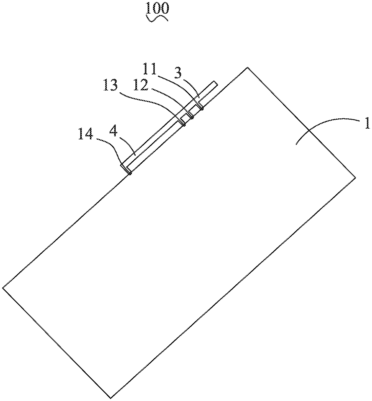
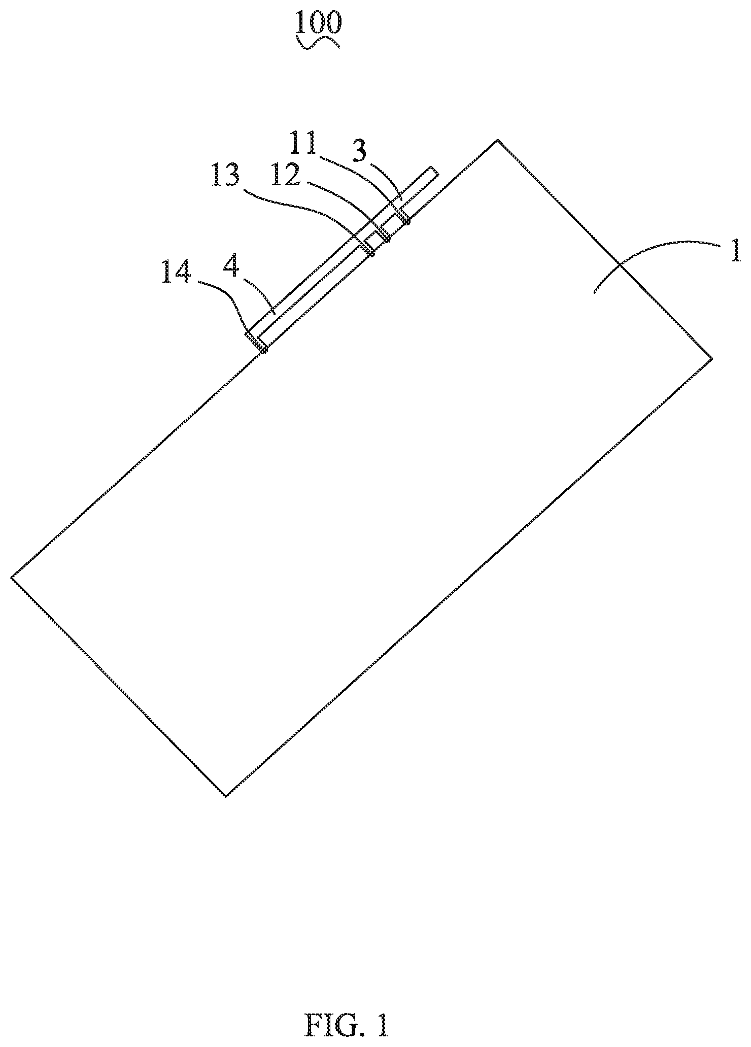
[0004] FIG. 1 is a partial structural schematic diagram of a compact dual-band MIMO antenna according to the present invention;
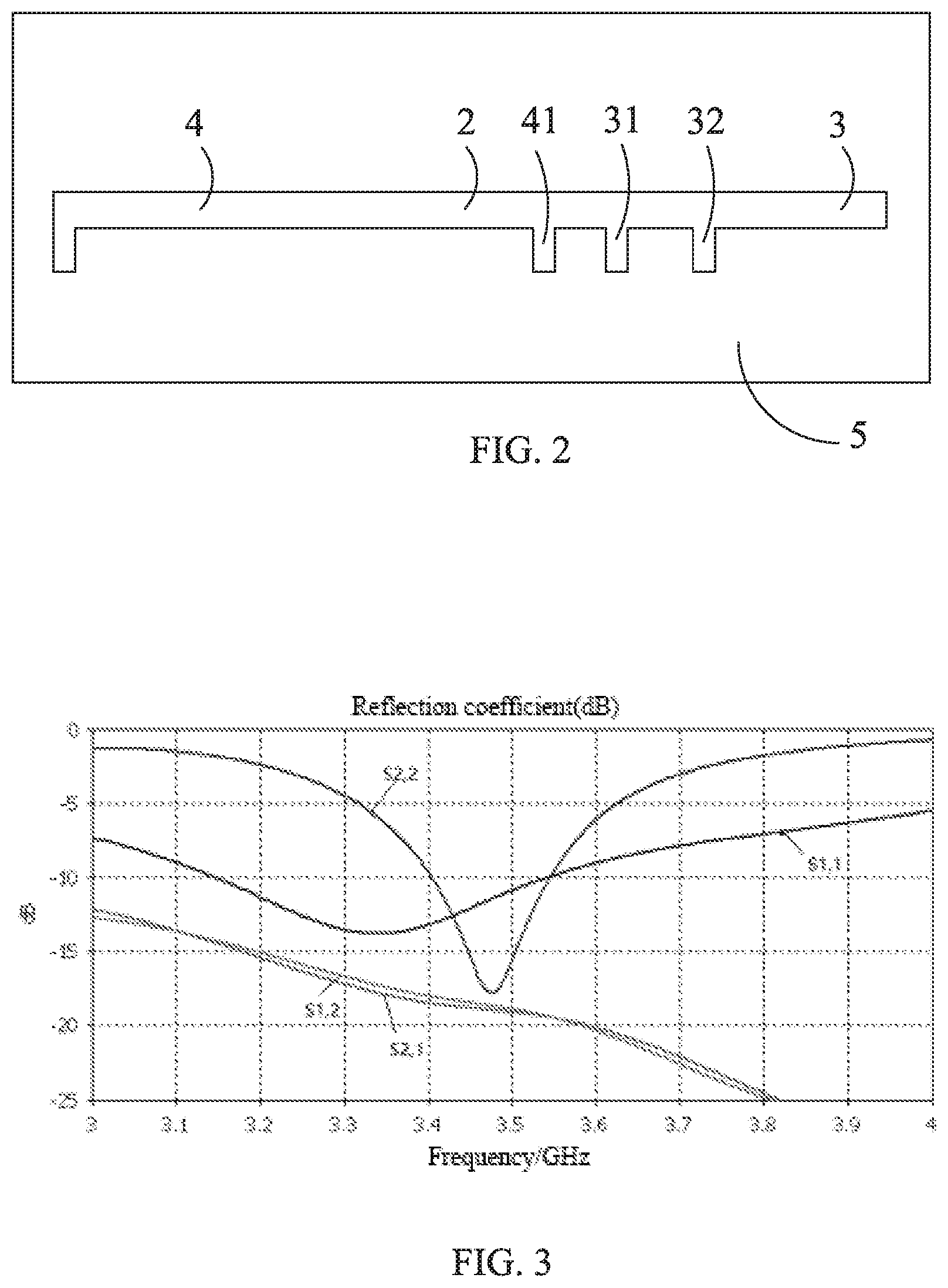
[0005] FIG. 2 is another partial structural schematic diagram of a compact dual-band MIMO antenna according to the present invention;
[0006] FIG. 3 illustrates S-parameter curves of a first antenna and a second antenna of a compact dual-band MIMO antenna according to the present invention;
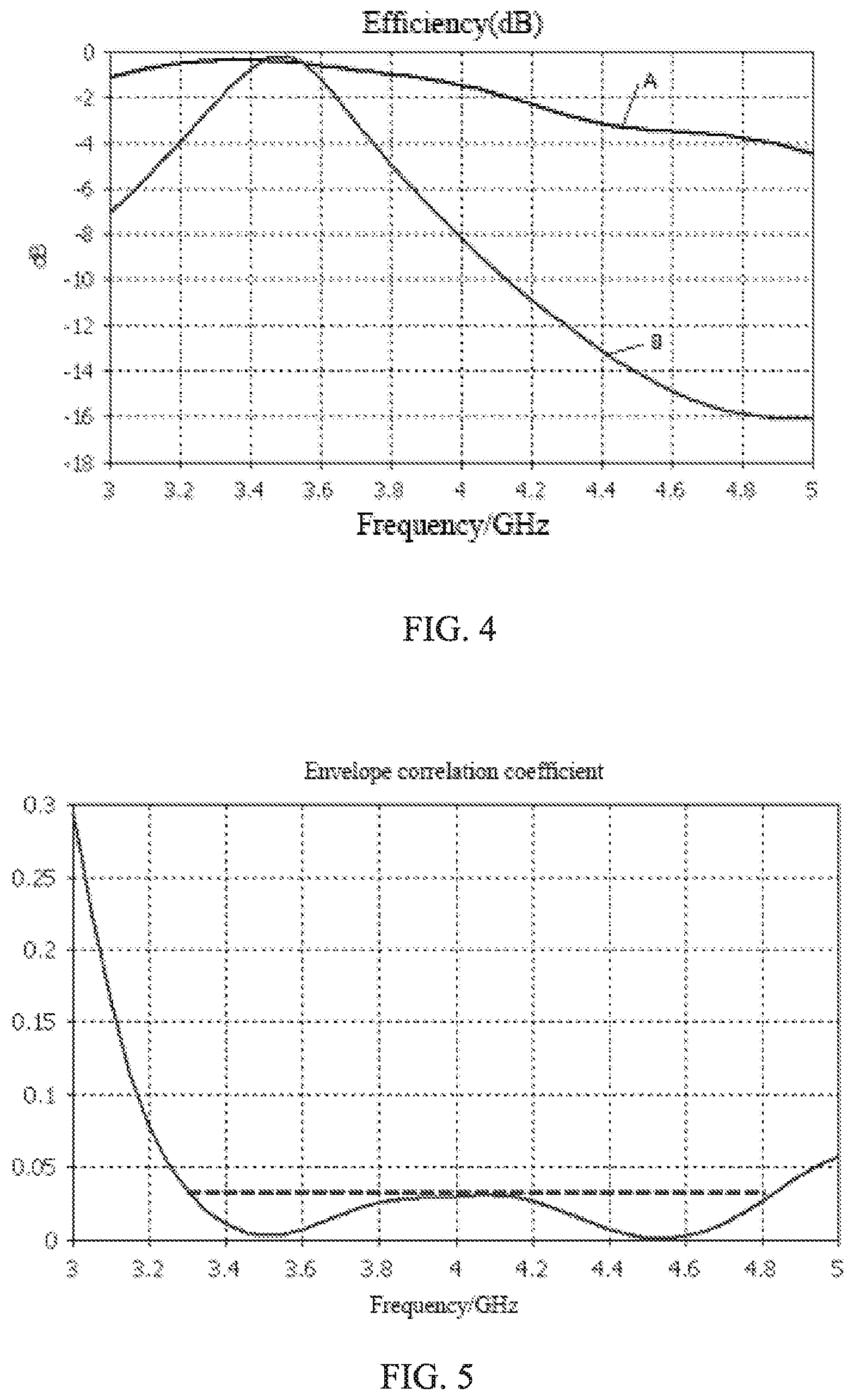
[0007] FIG. 4 illustrates efficiency curves of a first antenna and a second antenna of a compact dual-band MIMO antenna according to the present invention; and
[0008] FIG. 5 illustrates an envelope correlation coefficient curve between a first antenna and a second antenna of a compact dual-band MIMO antenna according to the present invention.
DESCRIPTION OF EMBODIMENTS
[0009] The present invention will be further illustrated with reference to the accompanying drawings and the embodiments.
[0010] Referring to FIG. 1 and FIG. 2, a first aspect of the present invention relates to a compact dual-band MIMO antenna 100, and the compact dual-band MIMO antenna 100 includes a system ground unit 1, a radiation arm 2 having an open-circuit end and a short-circuit end, a first antenna 3 formed at the open-circuit end, and a second antenna 4 formed at the short-circuit end. In one embodiment of the present invention, the first antenna 3 can be an inverted-F antenna, and the second antenna 4 can be a loop antenna that forms an orthogonal mode with the inverted-F antenna. It is appreciated that, the present invention is not limited thereto. For example, it is also possible that the second antenna 4 is an inverted-F antenna while the first antenna 3 is a loop antenna that forms an orthogonal mode with the inverted-F antenna, which can be specifically determined according to actual needs.
[0011] With continued reference to FIG. 1 and FIG. 2, the first antenna 3 further includes a grounding arm 31 connecting the radiation arm 2 with the system ground unit 1, and a first feeding arm 32 located between the grounding arm 31 and the open-circuit end. The second antenna 4 further includes a second feeding arm 41 located between the short-circuit end and the grounding arm 31.
[0012] The first antenna 3 and the second antenna 4 in the compact dual-band MIMO antenna 100 of the present invention share one radiation arm 2, such that the antenna can have a compact and simple structure, a small volume and a light weight, and it is convenient to manufacture and thus for mass production. In addition, the first antenna 3 may be an inverted-F antenna and the second antenna 4 is a loop antenna that forms an orthogonal mode with the inverted-F antenna, so that the isolation of the antenna structure can be improved.
[0013] With continued reference to FIG. 1 and FIG. 2, the system ground unit 1 sequentially includes a first feeding point 11, a first grounding point 12, a second feeding point 13, and a second grounding point 14. The first feeding arm 32 is connected to the first feeding point 11, and the first grounding point 12 is connected to the grounding arm 31. The second feeding point 13 is connected to the second feeding arm 41, and the second grounding point 14 is connected to the short-circuit end. In one embodiment, as shown in FIG. 2, the first feeding point 11 and the second feeding point 13 may be symmetrically disposed on both sides of the grounding arm 31.
[0014] In the compact dual-band MIMO antenna 100 according to the present invention, the first feeding arm 32 is connected to the first feeding point 11, and the first grounding point 12 is connected to the grounding arm 31. The second feeding point 13 is connected to the second feeding arm 41, and the second grounding point 14 is connected to the short-circuit end. Therefore, in the present invention, by appropriately setting the positions of the first feeding point 11 and the second feeding point 13 to be adjacent to each other, to facilitate a radio frequency front-end and T/R wiring and design.
[0015] With continued reference to FIG. 1 and FIG. 2, the compact dual-band MIMO antenna 100 further includes a substrate layer 5. The first antenna 3 and the second antenna 4 are disposed on the substrate layer 5. The substrate layer 5 is made of plastic, and the substrate layer 5 may be an antenna holder, a terminal back shell or a PBC and so on.
[0016] The first antenna 3 and the second antenna 4 are formed on the substrate layer 5 by an FPC, LDS or PCB process. It is appreciated that, the present invention is not limited to specific processes, and any other feasible process should be also within the scope of the present invention.
[0017] For the performance of the compact dual-band MIMO antenna 100, reference is made to FIGS. 3-5. In FIG. 3, S1, 1 is a reflection coefficient of the first antenna 3, and S2, 2 is a reflection coefficient of the second antenna 4, and S1, 2 and S2, 1 may represent the isolation between the first antenna 3 and the second antenna 4. In FIG. 4, a curve A indicates the efficiency of the first antenna 3, and a curve B indicates the efficiency of the second antenna 4. As can be seen from the drawing, both the first antenna 3 and the second antenna 4 can work in the band of Sub-6 GHz (3.3-3.6 GHz and 4.8-5.0 GHz), and the isolation is excellent in this band.
[0018] Compared with the related art, the present invention has following beneficial effects: the antenna has a compact structure and a high isolation; it has dual-band, and it has excellent performance in the dual bands; it has a simple structure, a small volume and a light weight, and it is convenient to manufacture and thus for mass production.
[0019] A second aspect of the present invention relates to a mobile terminal, which may be, for example, an electronic device such as a mobile phone, a computer, or a tablet. The mobile terminal includes the compact dual-band MIMO antenna 100 described above, and for details, reference can be made to the related descriptions above, which will not be described herein.
[0020] The mobile terminal of the present invention has the structure of the compact dual-band MIMO antenna 100 described above, and the first antenna 3 and the second antenna 4 share one radiation arm 2, which can make the structure of the antenna compact and simple, easy to process, small in volume and light in weight, and convenient for mass production. In addition, the first antenna 3 may be an inverted-F antenna, and the second antenna 4 is a loop antenna that forms an orthogonal mode with the inverted-F antenna, so that the isolation of the antenna structure can be improved.
[0021] What have been described above are only embodiments of the present invention, and it should be noted herein that those skilled in the art can make improvements without departing from the inventive concept of the present invention, but these are all within the scope of the present invention.
* * * * *
D00000
D00001
D00002
D00003
XML
uspto.report is an independent third-party trademark research tool that is not affiliated, endorsed, or sponsored by the United States Patent and Trademark Office (USPTO) or any other governmental organization. The information provided by uspto.report is based on publicly available data at the time of writing and is intended for informational purposes only.
While we strive to provide accurate and up-to-date information, we do not guarantee the accuracy, completeness, reliability, or suitability of the information displayed on this site. The use of this site is at your own risk. Any reliance you place on such information is therefore strictly at your own risk.
All official trademark data, including owner information, should be verified by visiting the official USPTO website at www.uspto.gov. This site is not intended to replace professional legal advice and should not be used as a substitute for consulting with a legal professional who is knowledgeable about trademark law.