Solid Electrolyte Material And Battery
NAGAMINE; KENTA ; et al.
U.S. patent application number 16/816278 was filed with the patent office on 2020-07-02 for solid electrolyte material and battery. The applicant listed for this patent is Panasonic Intellectual Property Management Co., Ltd.. Invention is credited to TETSUYA ASANO, KENTA NAGAMINE, AKIHIRO SAKAI.
| Application Number | 20200212481 16/816278 |
| Document ID | / |
| Family ID | 67144160 |
| Filed Date | 2020-07-02 |

| United States Patent Application | 20200212481 |
| Kind Code | A1 |
| NAGAMINE; KENTA ; et al. | July 2, 2020 |
SOLID ELECTROLYTE MATERIAL AND BATTERY
Abstract
Provided is a solid electrolyte material represented by the following composition formula (1): Li.sub.3-3d(Y.sub.1-xM.sub.x).sub.1+dX.sub.6 Formula (1) where M is an element having an ionic radius larger than that of Y; X is at least one kind of element selected from the group consisting of F, Cl, Br and I; 0<x.ltoreq.1; and -0.15.ltoreq.d.ltoreq.0.15.
| Inventors: | NAGAMINE; KENTA; (Osaka, JP) ; SAKAI; AKIHIRO; (Nara, JP) ; ASANO; TETSUYA; (Nara, JP) | ||||||||||
| Applicant: |
|
||||||||||
|---|---|---|---|---|---|---|---|---|---|---|---|
| Family ID: | 67144160 | ||||||||||
| Appl. No.: | 16/816278 | ||||||||||
| Filed: | March 12, 2020 |
Related U.S. Patent Documents
| Application Number | Filing Date | Patent Number | ||
|---|---|---|---|---|
| PCT/JP2018/043363 | Nov 26, 2018 | |||
| 16816278 | ||||
| Current U.S. Class: | 1/1 |
| Current CPC Class: | H01M 10/0525 20130101; C01P 2004/32 20130101; H01M 2300/008 20130101; H01M 10/0562 20130101; H01M 10/052 20130101; C01F 17/36 20200101; H01M 4/36 20130101; H01M 4/62 20130101; C01P 2006/40 20130101; C01P 2004/62 20130101; C01P 2004/51 20130101; H01M 4/525 20130101; H01B 1/06 20130101; C01P 2002/88 20130101; C01P 2004/61 20130101 |
| International Class: | H01M 10/0562 20060101 H01M010/0562; H01M 10/0525 20060101 H01M010/0525; C01F 17/36 20060101 C01F017/36 |
Foreign Application Data
| Date | Code | Application Number |
|---|---|---|
| Jan 5, 2018 | JP | 2018-000419 |
| Jan 5, 2018 | JP | 2018-000420 |
| Jan 5, 2018 | JP | 2018-000422 |
| Jan 5, 2018 | JP | 2018-000425 |
| Jan 5, 2018 | JP | 2018-000426 |
| Jan 5, 2018 | JP | 2018-000427 |
| Jan 5, 2018 | JP | 2018-000428 |
| Jan 5, 2018 | JP | 2018-000432 |
| Jan 5, 2018 | JP | 2018-000433 |
| Jan 5, 2018 | JP | 2018-000434 |
| Jan 5, 2018 | JP | 2018-000435 |
| Jan 26, 2018 | JP | 2018-011535 |
| Jan 26, 2018 | JP | 2018-011536 |
| Oct 1, 2018 | JP | 2018-186411 |
Claims
1. A solid electrolyte material represented by the following composition formula (1): Li.sub.3-3d(Y.sub.1-xM.sub.x).sub.1+dX.sub.6 Formula (1) where M is an element having an ionic radius larger than that of Y; X is at least one kind of element selected from the group consisting of F, Cl, Br and I; 0<x<1; and -0.15.ltoreq.d.ltoreq.0.15.
2. The solid electrolyte material according to claim 1, wherein M is one or more kinds of trivalent elements.
3. The solid electrolyte material according to claim 1, wherein M is one or more kinds of rare earth elements.
4. The solid electrolyte material according to claim 1, wherein M is one or more kinds of elements selected from the group consisting of La, Ce, Pr, Nd, Pm, Sm, Eu, Gd, Tb, Dy, and Ho.
5. The solid electrolyte material according to claim 4, wherein M is one or more kinds of elements selected from the group consisting of Sm, Eu, Tb, and Dy.
6. The solid electrolyte material according to claim 1, wherein M includes Sm.
7. The solid electrolyte material according to claim 1, wherein the formula (1) satisfies 0<x.ltoreq.0.5.
8. The solid electrolyte material according to claim 7, wherein the formula (1) satisfies 0.05.ltoreq.x.ltoreq.0.5.
9. The solid electrolyte material according to claim 1, wherein the formula (1) satisfies -0.05.ltoreq.d.ltoreq.0.15.
10. The solid electrolyte material according to claim 9, wherein the formula (1) satisfies -0.05.ltoreq.d.ltoreq.0.11.
11. The solid electrolyte material according to claim 10, wherein the formula (1) satisfies 0.ltoreq.d.ltoreq.0.11.
12. The solid electrolyte material according to claim 1, wherein X includes one or more kinds of elements selected from the group consisting of Br and Cl.
13. The solid electrolyte material according to claim 12, wherein X includes Br and Cl.
14. A battery, comprising: a positive electrode; a negative electrode; and an electrolyte layer provided between the positive electrode and the negative electrode, wherein at least one selected from the group consisting of the positive electrode, the negative electrode, and the electrolyte layer includes a solid electrolyte material according to claim 1.
Description
BACKGROUND
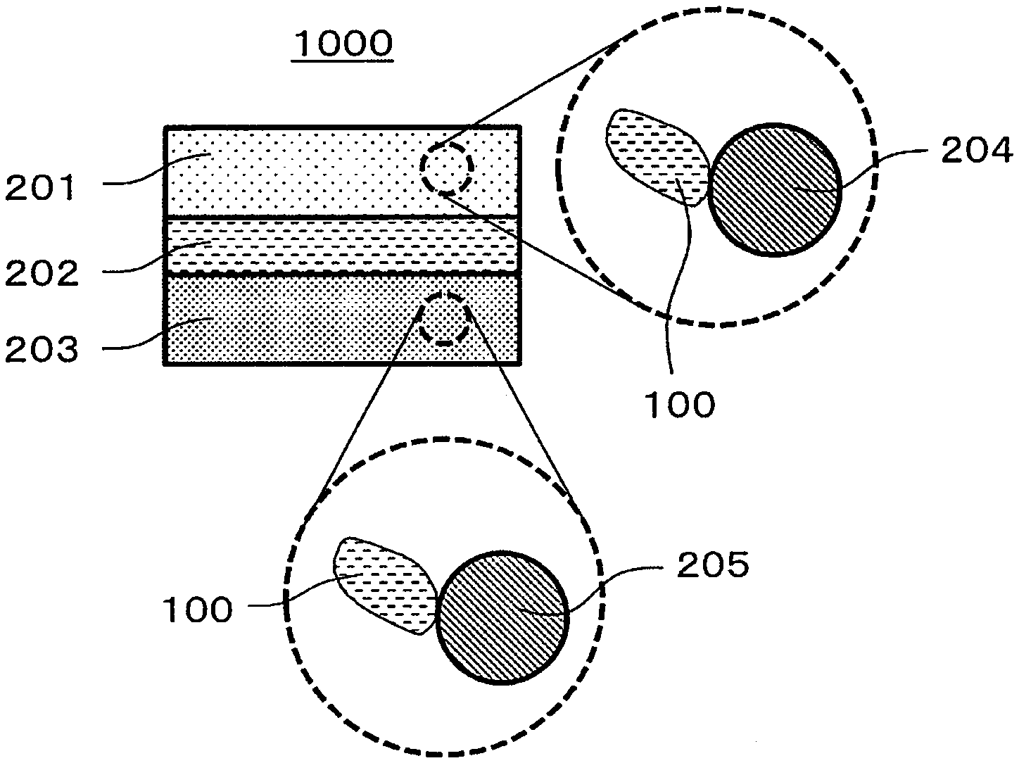
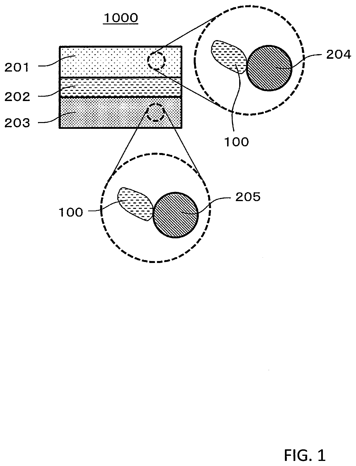
1. Technical Field
[0001] The present disclosure relates to a solid electrolyte material and a battery.
2. Description of the Related Art
[0002] Patent Literature 1 discloses an all-solid battery using a sulfide solid electrolyte,
CITATION LIST
Patent Literature
[0003] Patent Literature 1: Japanese Patent Application Publication No. 2011-129312
SUMMARY
[0004] In the prior art, realization of a solid electrolyte material having a lower melting point is desired.
[0005] The solid electrolyte material in one aspect of the present disclosure is represented by the following composition formula (1):
Li.sub.3-3d(Y.sub.1-xM.sub.x).sub.1+dX.sub.6 Formula (1)
[0006] where
[0007] M is an element having an ionic radius larger than that of Y;
[0008] X is at least one kind of element selected from the group consisting of F, Cl, Br and I;
[0009] 0<x.ltoreq.1; and
[0010] -0.15.ltoreq.d.ltoreq.0.15.
[0011] According to the present disclosure, a solid electrolyte material having a lower melting point can be realized.
BRIEF DESCRIPTION OF THE DRAWINGS
[0012] FIG. 1 is a cross-sectional view showing a schematic configuration of a battery in a second embodiment.
[0013] FIG. 2 is a graph showing DTA measurement results.
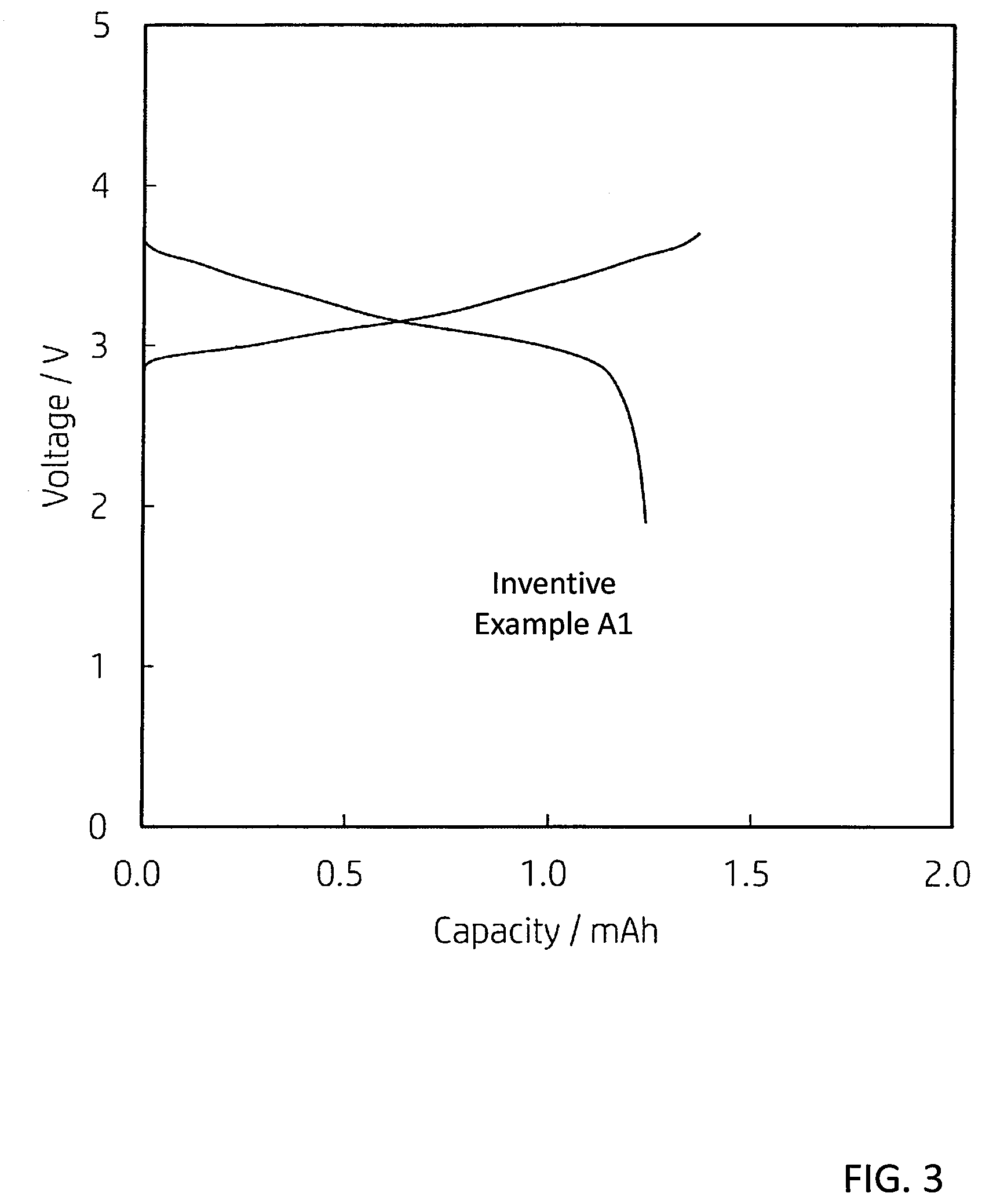
[0014] FIG. 3 is a graph showing an initial charge/discharge characteristic.
DETAILED DESCRIPTION OF THE EMBODIMENTS
[0015] Hereinafter, embodiments of the present disclosure will be described with reference to the drawings.
First Embodiment
[0016] The solid electrolyte material in the first embodiment is a solid electrolyte material represented by the following composition formula (1).
Li.sub.3-3d(Y.sub.1-xM.sub.x).sub.1+dX.sub.6 Formula (1)
[0017] M is an element having an ionic radius larger than that of Y. X is one or more kinds of elements selected from the group consisting of F, Cl, Br and I. 0<x.ltoreq.1 and -0.15.ltoreq.d.ltoreq.0.15 are satisfied.
[0018] According to the above configuration, a solid electrolyte material having a low melting point can be realized.
[0019] Moreover, according to the above configuration, an all-solid secondary battery excellent in a charge/discharge characteristic can be realized by using the solid electrolyte material of the first embodiment. In addition, by using the solid electrolyte material of the first embodiment, the all-solid secondary battery which does not include sulfur can be realized. In other words, if exposed to the atmosphere, the solid electrolyte material of the first embodiment does not have a configuration (for example, the configuration of Patent Literature 1) in which hydrogen sulfide is generated. As a result, an all-solid secondary battery which does not generate hydrogen sulfide and is excellent in safety can be realized.
[0020] The "ionic radius" in the present disclosure are values based on the definitions described in "Shannon et al., Acta A32 (1976) 751"
[0021] If the element M having an ionic radius larger that of Y is substituted for Y, the bond distance between the halide ion and the metal ion is made longer, so that the melting point would be lowered.
[0022] In the composition formula (1), M may be one or more kinds of trivalent elements.
[0023] If M is the one or more kinds of the trivalent elements, a solid solution can be formed in a relatively wide composition region.
[0024] In addition, in the composition formula (1), M may be one or more kinds of rare earth elements.
[0025] According to the above configuration, a solid electrolyte material having a low melting point can be realized.
[0026] In addition, in the composition formula (1), M may be one or more kinds of elements selected from the group consisting of La, Ce, Pr, Nd, Pm, Sm, Eu, Gd, Tb, Dy, and Ho.
[0027] According to the above configuration, a solid electrolyte material having a low melting point can be realized.
[0028] In addition, in the composition formula (1), M may be one or more kinds of elements selected from the group consisting of Sm, Eu, Tb, and Dy.
[0029] According to the above configuration, a solid electrolyte material having a low melting point can be realized.
[0030] In addition, in the composition formula (1), M may include Sm.
[0031] According to the above configuration, a solid electrolyte material having a low melting point can be realized.
[0032] In addition, in the composition formula (1), 0<x.ltoreq.0.5 may be satisfied. In addition, further, the value of x may satisfy 0.05.ltoreq.x.ltoreq.0.5.
[0033] According to the above configuration, a solid electrolyte material having both a low melting point and high ionic conductivity can be realized.
[0034] In addition, in the composition formula (1), -0.05.ltoreq.d.ltoreq.0.15 may be satisfied. The value of d may satisfy -0.05.ltoreq.d.ltoreq.0.11. In addition, 0.ltoreq.d.ltoreq.0.11 may be satisfied.
[0035] According to the above configuration, a solid electrolyte material having both a low melting point and high ionic conductivity can be realized.
[0036] In addition, in the composition formula (1), X may include one or more kinds of elements selected from the group consisting of Cl and Br.
[0037] According to the above configuration, a solid electrolyte material having both a low melting point and high ionic conductivity can be realized.
[0038] In addition, in the composition formula (1), X may include Br and Cl.
[0039] According to the above configuration, a solid electrolyte material having both a low melting point and high ionic conductivity can be realized.
[0040] Note that the solid electrolyte material in the first embodiment may be crystalline or amorphous.
[0041] In addition, a shape of the solid electrolyte material in the first embodiment is not particularly limited, and may be, for example, an acicular shape, a spherical shape, an elliptical spherical shape, or a fibrous shape. For example, the solid electrolyte material in the first embodiment may be particles. In addition, the solid electrolyte material in the first embodiment may be formed into a pellet shape or a plate shape by pressurization after a plurality of particles are stacked.
[0042] For example, if the shape of the solid electrolyte material in the first embodiment is particulate (for example, spherical), the median diameter thereof may be not less than 0.1 .mu.m and not more than 100 .mu.m.
[0043] In addition, in the first embodiment, the median diameter may be not less than 0.5 .mu.m and not more than 10 .mu.m.
[0044] According to the above configuration, ionic conductivity can be further improved. In addition, a better dispersion state of the solid electrolyte material in the first embodiment and an active material can be formed.
[0045] In addition, in the first embodiment, the solid electrolyte material may be smaller than the median diameter of the active material.
[0046] According to the above configuration, a better dispersion state of the solid electrolyte material in the first embodiment and the active material can be formed.
[0047] <Manufacturing Method of Solid Electrolyte Material>
[0048] The solid electrolyte material in the first embodiment may be manufactured by the following method, for example.
[0049] Binary halide raw material powders are prepared so as to have a blending ratio of a target composition. For example, if Li.sub.3Y.sub.0.9Sm.sub.0.1Br.sub.3Cl.sub.3 is produced, LiBr, YCl.sub.3 and SmCl.sub.3 are prepared in a molar ratio of approximately 3.0 : 0.9 : 0.1. In consideration of the change in composition during a synthesis process, the blending ratio may be adjusted in advance so as to cancel the change. The above-mentioned "d" and "x" can be adjusted by adjusting the raw materials, the blending ratio and, the synthesis process.
[0050] The raw material is not limited to the above. For example, a combination of LiCl and YBr.sub.3 or a composite anion compound such as LiBr.sub.0.5Cl.sub.0.5 may be used as the raw material. In addition, as a raw material, a mixture of an oxygen-including substance such as an oxide, hydroxide, sulfate, or nitrate and a halide such as ammonium halide may be used.
[0051] The raw material powders are mixed well using a mortar with a pestle. Alternatively, the raw material powders are mixed well using a ball mill or a mixer. Thereafter, the mixture is sintered in a vacuum or in an inert atmosphere. It is desirable that the mixture is sintered, for example, for 1 hour or longer within a range of not less than 100 degrees Celsius and not more than 650 degrees Celsius.
[0052] In this way, the solid electrolyte material including the composition as described above is provided.
Second Embodiment
[0053] Hereinafter, the second embodiment will be described. The description which has been set forth in the above-described first embodiment is omitted appropriately.
[0054] The battery in the second embodiment is configured using the solid electrolyte material described in the first embodiment.
[0055] The battery in the second embodiment comprises a positive electrode, a negative electrode, and an electrolyte layer.
[0056] The electrolyte layer is a layer provided between the positive electrode and the negative electrode.
[0057] At least one of the positive electrode, the electrolyte layer, and the negative electrode includes the solid electrolyte material in the first embodiment.
[0058] According to the above configuration, the charge/discharge characteristic of he battery can be improved.
[0059] A solid electrolyte material having a low melting point is softer than a solid electrolyte material having a higher melting point. As a result, adhesiveness of the interface between the active material and the solid electrolyte material can be satisfactorily formed during pressure molding. As a result, the charge/discharge characteristic of a battery can be improved. In addition, even if the active material and the solid electrolyte material are integrated by sintering, it is possible to realize formation of a favorable interface and suppression of a side reaction.
[0060] The solid electrolyte material in the first embodiment may be included in a plurality of particles, and the plurality of the particles may be included in the positive electrode layer, the electrolyte layer, or the negative electrode layer. The solid electrolyte material included in the plurality of the particles may be only one kind or a plurality of kinds. In addition, the components of the solid electrolyte material may be the same in all of the plurality of the particles. Alternatively, at least one of the plurality of the particles may have a solid electrolyte material component different from those of other particles. In addition, the at least one of the plurality of the particles may include a plurality of regions having different compositions from each other. For example, a solid battery may be configured by using only Li.sub.3Y.sub.1-xM.sub.xX.sub.6 as a solid electrolyte material. Alternatively, a solid battery described in the first embodiment may be configured by mixing Li.sub.3Y.sub.1-xM-X.sub.6 particles together with Li.sub.3YX.sub.5 particles.
[0061] According to the above configuration, a favorable interface between the solid electrolytes can be formed. A favorable interface between the solid electrolyte and the active material can be formed.
[0062] A specific example of the battery in the second embodiment will be described below.
[0063] FIG. 1 is a cross-sectional view showing a schematic configuration of a battery 1000 in the second embodiment.
[0064] The battery 1000 in the second embodiment comprises a positive electrode 201, a negative electrode 203, and an electrolyte layer 202.
[0065] The positive electrode 201 includes positive electrode active material particles 204 and solid electrolyte particles 100.
[0066] The electrolyte layer 202 is disposed between the positive electrode 201 and the negative electrode 203.
[0067] The electrolyte layer 202 includes an electrolyte material (for example, a solid electrolyte material).
[0068] The negative electrode 203 includes negative electrode active material particles 205 and the solid electrolyte particles 100.
[0069] The solid electrolyte particles 100 are particles each consisting of the solid electrolyte material in the first embodiment or particles each including the solid electrolyte material in the first embodiment as a main component.
[0070] The positive electrode 201 includes a material having a characteristic of storing and releasing metal ions (for example, lithium ions). The positive electrode 201 includes, for example, a positive electrode active material (for example, the positive electrode active material particles 204).
[0071] As the positive electrode active material, for example, a lithium-containing transition metal oxide (e.g., Li(NiCoAl)O.sub.2, or LiCoO.sub.2), a transition metal fluoride, a polyanion material, a fluorinated polyanion material, a transition metal sulfide, a transition metal oxyfluoride, a transition metal oxysulfide, and a transition metal oxynitride can be used.
[0072] The median diameter of each of the positive electrode active material particles 204 may be not less than 0.1 .mu.m and not more than 100 .mu.m. If the median diameter of each of the positive electrode active material particles 204 is not less than 0.1 .mu.m, the positive electrode active material particles 204 and the halide solid electrolyte material can form a good dispersion state in the positive electrode. As a result, the charge/discharge characteristic of the battery is improved. In addition, if the median diameter of each of the positive electrode active material particles 204 is not more than 100 .mu.m, lithium diffusion in the positive electrode active material particles 204 is accelerated. As a result, the battery can operate at a high output.
[0073] The median diameter of each of the positive electrode active material particles 204 may be larger than the median diameter of the halide solid electrolyte material. In this case, the favorable dispersion state of the positive electrode active material particle 204 and the halide solid electrolyte material can be formed.
[0074] With regard to a volume ratio "v : 100-v" between the positive electrode active material particles 204 and the halide solid electrolyte material included in the positive electrode 201, 30.ltoreq.v.ltoreq.95 may be satisfied. In a case of 30.ltoreq.v, a sufficient battery energy density can be secured. In addition, if v.ltoreq.95, an operation at a high output can be realized.
[0075] The thickness of the positive electrode 201 may be 10 to 500 .mu.m. If the thickness of the positive electrode is 10 .mu.m or more, a sufficient battery energy density can be ensured. In addition, if the thickness of the positive electrode is 500 .mu.m or less, an operation at a high output can be realized.
[0076] The electrolyte layer 202 is a layer including an electrolyte material. The electrolyte material is, for example, a solid electrolyte material. In other words, the electrolyte layer 202 may be a solid electrolyte layer.
[0077] The solid electrolyte layer may contain the solid electrolyte material in the first embodiment as a main component. In other words, the solid electrolyte layer may include the solid electrolyte material in the above-described first embodiment, for example, at 50% or more (namely, 50% by weight or more) of a weight ratio electrolyte with respect to the entire solid electrolyte layer.
[0078] According to the above configuration, a solid electrolyte material having a low melting point can be realized.
[0079] In addition, the solid electrolyte layer may include the solid electrolyte material in the above-described first embodiment, for example, at 70% or more (namely, 70% by weight or more) of the weight ratio electrolyte with respect to the entire solid electrolyte layer.
[0080] According to the above configuration, a solid electrolyte material having a low melting point can be realized.
[0081] In addition, the solid electrolyte layer includes the solid electrolyte material in the above-described first embodiment as a main component, and further includes inevitable impurities, starting materials and auxiliary substances used when the solid electrolyte material is synthesized, or decomposition products.
[0082] In addition, the solid electrolyte layer may include the solid electrolyte material in the first embodiment, for example, at 100% (namely, 100% by weight) by weight with respect to the entire solid electrolyte layer, excluding impurities mixed inevitably.
[0083] According to the above configuration, a solid electrolyte material having a low melting point can be realized.
[0084] As described above, the solid electrolyte layer may be composed only of the solid electrolyte material in the first embodiment.
[0085] Alternatively, the solid electrolyte layer may be composed only of a solid electrolyte material different from the solid electrolyte material in the first embodiment. As the solid electrolyte material different from the solid electrolyte material in the first embodiment, for example, Li.sub.2MgX.sub.4, Li.sub.2FeX.sub.4, Li(Al, Ga, In)X.sub.4, Li.sub.3(Al, Ga, In)X.sub.6, or Lil may be used. Here, X includes at least one selected from the group consisting of Cl, Br, and
[0086] The solid electrolyte layer may include simultaneously the solid electrolyte material in the first embodiment and the solid electrolyte material different from the solid electrolyte material in the first embodiment. At this time, both may be dispersed uniformly. Alternatively, the layer formed of the solid electrolyte material in the first embodiment and the layer formed of the solid electrolyte material different from the solid electrolyte material in the first embodiment are sequentially arranged in the stacking direction of the battery.
[0087] The thickness of the solid electrolyte layer may be not less than 1 .mu.m and not more than 100 .mu.m. If the thickness of the solid electrolyte layer is not less than 1 .mu.m, the positive electrode 201 and the negative electrode 203 are easily separated. In addition, if the thickness of the solid electrolyte layer is not more than 100 .mu.m, an operation at a high output can be realized.
[0088] The negative electrode 203 includes a material having a characteristic of storing and releasing metal ions (for example, lithium ions). The negative electrode 203 includes, for example, a negative electrode active material (for example, negative electrode active material particles 205).
[0089] As the negative electrode active material, a metal material, a carbon material, an oxide, a nitride, a tin compound, or a silicon compound can be used. The metal material may be a single metal. Alternatively, the metal material may be an alloy. Examples of the metal material include lithium metal and lithium alloy. Examples of the carbon material include natural graphite, coke, graphitized carbon, carbon fiber, spherical carbon, artificial graphite, and amorphous carbon. From the viewpoint of capacity density, silicon (Si), tin (Sn), a silicon compound, or a tin compound can be used. If a negative electrode active material having a low average reaction voltage is used, the effect of suppressing electrolysis by the solid electrolyte material in the first embodiment is better exhibited.
[0090] The median diameter of each of the negative electrode active material particles 205 may be not less than 0.1 .mu.m and not more than 100 .mu.m. If the median diameter of each of the negative electrode active material particles 205 is not less than 0.1 .mu.m, the negative electrode active material particles 205 and the solid electrolyte particles 100 can form a good dispersion state in the negative electrode. As a result, the charge/discharge characteristic of the battery is improved. In addition, if the median diameter of each of the negative electrode active material particles 205 is not more than 100 .mu.m, the lithium diffusion in the negative electrode active material particles 205 is accelerated. For this reason, the battery can operate at a high output.
[0091] The median diameter of each of the negative electrode active material particles 205 may be larger than the median diameter of the solid electrolyte particles 100. As a result, the favorable dispersion state of the negative electrode active material particle 205 and the halide solid electrolyte material can be formed.
[0092] With regard to the volume ratio "v : 100-v" of the negative electrode active material particles 205 and the solid electrolyte particles 100 included in the negative electrode 203, 30 v.ltoreq.v.ltoreq.95 may be satisfied. In a case of 30.ltoreq.v, a sufficient battery energy density can be secured. In addition, if v.ltoreq.95, an operation at a high output can be realized.
[0093] The thickness of the negative electrode 203 may be not less than 10 .mu.m and not more than 500 .mu.m. If the thickness of the negative electrode is not less than 10 .mu.m, the sufficient battery energy density can be secured. In addition, if the thickness of the positive electrode is not more than 500 .mu.m, an operation at a high output can be realized.
[0094] At least one of the positive electrode 201, the electrolyte layer 202, and the negative electrode 203 may include a sulfide solid electrolyte or an oxide solid electrolyte for the purpose of improving ionic conductivity, chemical stability, and electrochemical stability. As the sulfide solid electrolyte, Li.sub.2S--P.sub.2S.sub.5, Li.sub.2S--SiS.sub.2, Li.sub.2S--B.sub.2S.sub.3, Li.sub.2S--GeS.sub.2, or Li.sub.3.25Ge.sub.0.75P.sub.0.75S.sub.4, Li.sub.10GeP.sub.2S.sub.12 can be used. As the oxide solid electrolyte, a NASICON solid electrolyte typified by LiTi.sub.2(PO.sub.4).sub.3 and its element substitution, a (LaLi)TiO.sub.3 perovskite solid electrolyte, a LIS ICON solid electrolyte typified by Li.sub.14ZnGe.sub.4O.sub.16, Li.sub.4SiO.sub.4, or LiGeO.sub.4 and its element substitution, a garnet solid electrolyte typified by Li.sub.7La.sub.3Zr.sub.2O.sub.12 and its element substitution, Li.sub.3N and its H substitution, or Li.sub.3PO.sub.4 and its N substitution can be used.
[0095] At least one of the positive electrode 201, the electrolyte layer 202, and the negative electrode 203 may include an organic polymer solid electrolyte for the purpose of increasing ionic conductivity. As the organic polymer solid electrolyte, for example, a compound of a polymer compound and a lithium salt can be used. The polymer compound may have an ethylene oxide structure. Since the polymer compound has the ethylene oxide structure, a large amount of lithium salt can be included, and the ionic conductivity can be further increased. As the lithium salt, LiPF.sub.6, LiBF.sub.4, LiSbF.sub.6, LiAsF.sub.6, LiSO6.sub.3CF.sub.3, LiN(SO.sub.2CF.sub.3).sub.2, LiN(SO.sub.2C.sub.2F.sub.5).sub.2, LiN(SO.sub.2CF.sub.3)(SO.sub.2C.sub.4F.sub.9), or LiC(SO.sub.2CF.sub.3).sub.3 can be used. As the lithium salt, one lithium salt selected from these may be used alone. Alternatively, a mixture of two or more lithium salts selected from these may be used as the lithium salt.
[0096] At least one of the positive electrode 201, the electrolyte layer 202, and the negative electrode 203 may include a non-aqueous electrolyte solution, a gel electrolyte, and an ionic liquid for the purpose of facilitating exchange of lithium ions and improving the output characteristic of the battery.
[0097] The non-aqueous electrolyte solution includes a non-aqueous solvent and a lithium salt dissolved in the non-aqueous solvent. As the non-aqueous solvent, a cyclic carbonate solvent, a chain carbonate solvent, a cyclic ether solvent, a chain ether solvent, a cyclic ester solvent, a chain ester solvent, or a fluorine solvent can be used. Examples of the cyclic carbonate solvent include ethylene carbonate, propylene carbonate, and butylene carbonate. Examples of the chain carbonate solvent include dimethyl carbonate, ethyl methyl carbonate, and diethyl carbonate. Examples of the cyclic ether solvent include tetrahydrofuran, 1,4-dioxane, and 1,3-dioxolane. Examples of the chain ether solvent include 1,2-dimethoxyethane and 1,2-diethoxyethane. Examples of the cyclic ester solvent include .gamma.-butyrolactone. Examples of the chain ester solvent include methyl acetate. Examples of the fluorine solvent include fluoroethylene carbonate, methyl fluoropropionate, fluorobenzene, fluoroethyl methyl carbonate, and fluorodimethylene carbonate. As the non-aqueous solvent, one non-aqueous solvent selected from these can be used alone. Alternatively, a combination of two or more non-aqueous solvents selected from these can be used as the non-aqueous solvent. The non-aqueous electrolyte solution may contain at least one fluorine solvent selected from the group consisting of fluoroethylene carbonate, methyl fluoropropionate, fluorobenzene, fluoroethyl methyl carbonate, and fluorodimethylene carbonate. As the lithium salt, LiPF.sub.6, LiBF.sub.4, LiSbF.sub.6, LiAsF.sub.6, LiSO3CF.sub.3, LiN(SO.sub.2CF.sub.3).sub.2, LiN(SO.sub.2C.sub.2F.sub.5).sub.2, LiN(SO.sub.2CF.sub.3)(SO.sub.2C.sub.4F.sub.9), or LiC(SO.sub.2CF.sub.3).sub.3 can be used. As the lithium salt, one lithium salt selected from these may be used alone. Alternatively, a mixture of two or more lithium salts selected from these may be used as the lithium salt. The concentration of the lithium salt is, for example, in the range of 0.5 to 2 mol/liter.
[0098] As the gel electrolyte, a polymer material including a non-aqueous electrolyte solution can be used. As the polymer material, polyethylene oxide, polyacrylonitrile, polyvinylidene fluoride, polymethyl methacrylate, or a polymer having an ethylene oxide bond may be used.
[0099] The cation which forms the ionic liquid is an aliphatic chain quaternary salt such as tetraalkylammonium or tetraalkylphosphonium, an aliphatic cyclic ammonium such as pyrrolidinium, morpholinium, imidazolinium, tetrahydropyrimidinium, piperazinium or piperidinium, a nitrogen-including heterocyclic aromatic cation such as pyridinium or imidazolium. The anion which forms the ionic liquid is PF.sub.6--, BF.sub.4--, SbF.sub.6--, AsF.sub.6--, SO.sub.3CF.sub.3--, N(SO.sub.2CF.sub.3).sub.2--, N(SO.sub.2C.sub.2F.sub.5).sub.2--, N(SO.sub.2CF.sub.3)(SO.sub.2C.sub.4F.sub.9)--, or C(SO.sub.2CF.sub.3).sub.3--. The ionic liquid may contain a lithium salt.
[0100] At least one of the positive electrode 201, the electrolyte layer 202, and the negative electrode 203 may include a binder for the purpose of improving adhesion between the particles. The binder is used to improve the binding property of the material which forms the electrode. The binders include polyvinylidene fluoride, polytetrafluoroethylene, polyethylene, polypropylene, aram id resin, polyamide, polyimide, polyamideimide, polyacrylonitrile, polyacrylic acid, polyacrylic acid methyl ester, polyacrylic acid ethyl ester, polyacrylic acid hexyl ester, polymethacrylic acid, polymethacrylic acid methyl ester, polymethacrylic acid ethyl ester, polymethacrylic acid hexyl ester, polyvinyl acetate, polyvinylpyrrolidone, polyether, polyethersulfone, hexafluoropolypropylene, styrene butadiene rubber, or carboxymethylcellulose. The binder includes a copolymer of two or more materials selected from the group consisting of tetrafluoroethylene, hexafluoroethylene, hexafluoropropylene, perfluoroalkyl vinyl ether, vinylidene fluoride, chlorotrifluoroethylene, ethylene, propylene, pentafluoropropylene, fluoromethyl vinyl ether, acrylic acid, and hexadiene. In addition, two or more kinds selected from these may be mixed and used as a binder.
[0101] In addition, at least one of the positive electrode .COPYRGT.and the negative electrode 203 may include a conductive agent as necessary.
[0102] The conductive agent is used to lower electrode resistance. Examples of the conductive agent include graphite such as natural graphite or artificial graphite, carbon black such as acetylene black or ketjen black, a conductive fiber such as a carbon fiber or a metal fiber, a metal powder such as carbon fluoride or aluminum, a conductive whisker such as zinc oxide or potassium titanate, a conductive metal oxide such as titanium oxide, or a conductive polymer compound such as polyaniline, polypyrrole, or polythiophene. In addition, cost reduction can be achieved by using carbon conductive agent as the conductive agent.
[0103] Note that the battery in the second embodiment can be configured as a battery having various shapes such as a coin shape, a cylindrical shape, a prism shape, a sheet shape, a button shape, a flat shape, or a laminated shape.
EXAMPLES
[0104] Hereinafter, details of the present disclosure will be described with reference to inventive examples and comparative examples.
[0105] <<Inventive Example A1>>
[0106] [Production of Solid Electrolyte Material]
[0107] In an argon atmosphere with a dew point of not more than -60.degree. C., LiBr, YCl.sub.3, and SmCl.sub.3 were prepared as raw powders at a molar ratio LiBr : YCl.sub.3: SmCl.sub.3=3:0.95: 0.05. These were ground and mixed in a mortar, and then, sintered at 500.degree. C. for 3 hours in an electric furnace. Subsequently, the coarse particles were ground using a pestle and a mortar.
[0108] Thus, a solid electrolyte material powder represented by the composition formula of Li.sub.3Y.sub.0.95Sm.sub.0.05Br.sub.3Cl.sub.3 (hereinafter, referred to as powder A1) was provided.
[0109] [Measurement of Melting Point]
[0110] The melting point of the powder A1 was measured using TG-DTA manufactured by RIGAKU Corporation in an argon atmosphere with a dew point of not more than -30.degree. C. More specifically, the melting point of the powder A1 was measured as follows. In other words, in a dry room having a dew point of not more than -30.degree. C., approximately 10 mg of the powder A1 was put into a platinum container and heated to 600.degree. C. at a heating rate of 10 K/min under an argon flow. The endothermic start point of the endothermic peak observed at that time was taken as the melting point. If a plurality of endothermic peaks appeared, the one observed on the lower temperature side was regarded as the melting point. FIG. 2 shows DTA patterns of the inventive examples A1 to A3 and the comparative example B1. The inventive examples A2 and A3 and the comparative example B1 will be described later.
[0111] [Production of Secondary Battery]
[0112] In an argon glove box, the powder A1 and Li(Ni, Co, Mn)O.sub.2, which is an active material, were prepared at a volume ratio of 50:50. These were mixed in an agate mortar to prepare a mixture.
[0113] In an insulating outer cylinder, 60 mg of a sulfide solid electrolyte Li.sub.6PS.sub.5Cl, the powder A1 the amount of which corresponded to a thickness of 700 .mu.m after pressure molding, and 9.6 mg of the above-mentioned mixture were stacked in this order. These were pressure-molded at a pressure of 720 MPa to provide a first electrode and a solid electrolyte layer.
[0114] Next, metal In foil and Li foil were stacked on the opposite side to the side which was in contact with the first electrode of the solid electrolyte layer. These were pressure-molded at a pressure of 80 MPa to produce a stacking structure of the first electrode, the solid electrolyte layer, and a second electrode.
[0115] Next, stainless-steel current collectors were disposed on the upper and lower parts of the stacking structure, and current collector leads were attached to the current collectors. Finally, an insulating ferrule was used to block and seal the inside of the insulating outer cylinder from the outside atmosphere. In this way, a battery A1 of the inventive example 1 was produced.
[0116] [Charge/Discharge Test]
[0117] FIG. 3 is a graph showing an initial charge/discharge characteristic of the battery A1. The result of FIG. 3 was measured by the following method. In other words, first, the battery A1 was placed in a thermostatic chamber at 25.degree. C. Next, constant current charging was performed at a current value of 0.05 C rate (20 hour rate) with respect to a theoretical capacity of the battery, and the charging was terminated at a voltage of 3.7 V. Next, the battery was discharged at a current value of 0.05 C rate, and the discharge was terminated at a voltage of 1.9V. As a result of the measurement, the initial discharge capacity of the secondary battery of the inventive example A1 was 1.2 mAh.
[0118] <<Inventive Examples A2 to A6>>,
[0119] In an argon atmosphere with a dew point of not more than -60.degree. C., LiBr, YCl.sub.3, and MCl.sub.3 were prepared at a molar ratio of LiBr : YCl.sub.3: MCl.sub.3=3: 1--x: x. Here, M is Sm, Eu, Tb, or Dy. Except for the above, solid electrolyte material powders A2 to A6 were prepared in the same manner as in the inventive example 1. The value of x and the element M are shown in Table 1.
[0120] [Measurement of Melting Point]
[0121] Melting points were measured using the powders A2 to A6 in the same manner as in the inventive example A1.
[0122] [Production of Secondary Battery]
[0123] In the same manner as in the inventive example A1 batteries A2 to A6 were produced using the powders A2 to A6, and the charge/discharge test was performed. The initial charge/discharge characteristics of the batteries A2 to A6 were as good as the battery A1.
[0124] >>Comparative Examples B1 to B3>>
[0125] In an argon atmosphere with a dew point of not more than -60.degree. C., LiBr, YCl.sub.3, and MCl.sub.3 were prepared at a molar ratio of LiBr : YCl.sub.3:MCl.sub.3=3: 1-x: x. Here, M is Er or Lu. Except for the above, solid electrolyte material powders B1 to B3 were provided in the same manner as in the inventive example 1. Using the powders B1 to B3, the melting points were measured in the same manner as in the inventive example A1.
[0126] Table 1 shows the compositions and melting points in the inventive examples A1 to A6 and the comparative examples B1 to B3.
TABLE-US-00001 TABLE 1 Melting Composition M x Point/.degree. C. Inventive Li.sub.3Y.sub.0.95Sm.sub.0.05Br.sub.3Cl.sub.3 Sm 0.05 468 example A1 Inventive Li.sub.3Y.sub.0.9Sm.sub.0.1Br.sub.3Cl.sub.3 Sm 0.1 466 example A2 Inventive Li.sub.3Y.sub.0.8Sm.sub.0.2Br.sub.3Cl.sub.3 Sm 0.2 432 example A3 Inventive Li.sub.3Y.sub.0.9Eu.sub.0.1Br.sub.3Cl.sub.3 Eu 0.1 469 example A4 Inventive Li.sub.3Y.sub.0.9Tb.sub.0.1Br.sub.3Cl.sub.3 Tb 0.1 471 example A5 Inventive Li.sub.3Y.sub.0.9Dy.sub.0.1Br.sub.3Cl.sub.3 Dy 0.1 470 example A6 Comparative Li.sub.3YBr.sub.3Cl.sub.3 -- 0 475 Example B1 Comparative Li.sub.3Y.sub.0.9Er.sub.0.1Br.sub.3Cl.sub.3 Er 0.1 476 Example B2 Comparative Li.sub.3Y.sub.0.9Lu.sub.0.1Br.sub.3Cl.sub.3 Lu 0.1 477 Example B3
[0127] <<Discussion 1>>
[0128] It can be seen that each of the powders A1 to A6 of the inventive examples A1 to A6 has a lower melting point than the powders B1 to B3 of the comparative examples B1 to B3. In other words, it can be seen that the melting point of the solid electrolyte material is lowered, if an element having an ionic radius larger than that of Y, such as Sm, Eu, Tb, and Dy, is substituted for Y of Li.sub.3YBr.sub.3Cl.sub.3. This would be because, for example, if an element having an ionic radius larger than that of Y is substituted for Y in Li.sub.3YX.sub.6, the bond distance between the halide ion and the metal ion both of which form the crystal is increased, and the bonding force is weakened.
[0129] On the other hand, as shown in the powders B2 and B3 of the comparative examples B2 and B3, if an element having an ionic radius smaller than that of Y, such as Er and Lu, is substituted, no lowering in the melting point of the solid electrolyte material is observed. This would be because, for example, if an element having an ionic radius smaller than that of Y is substituted for Y of Li.sub.3YX.sub.6, the bond distance between the halide ion and the metal ion both of which form the crystal is shortened.
[0130] In addition, as shown in the powders A1 to A3 of the inventive examples A1 to A3, it can be seen that the melting point of the solid electrolyte material is further lowered with an increase in the amount of the element having an ionic radius larger than that of Y to be substituted is increased. Therefore, if it is desired to further lower the melting point of the solid electrolyte material, the substitution amount of the element having an ionic radius larger than that of Y is increased.
[0131] In addition, a solid battery using the solid electrolyte material of the present disclosure can form a good solid electrolyte material/active material interface operable as a battery, even if the solid battery is molded by pressure molding at room temperature. As a result, the resistance of the battery can be lowered, and the charge/discharge capacity of the battery is improved. This is because a solid electrolyte material having a low melting point is softer than a material having a high melting point. Furthermore, since the solid electrolyte material of the present disclosure does not contain sulfur as a constituent element, hydrogen sulfide, which is harmful, is not generated.
[0132] Table 2 shows atomic numbers, element names, and ionic radii according to Shannon's definition.
TABLE-US-00002 TABLE 2 Atomic number Element ionic radius/.ANG. 39 Y 0.900 57 La 1.032 58 Ce 1.010 59 Pr 0.990 60 Nd 0.983 61 Pm 0.970 62 Sm 0.958 63 Eu 0.947 64 Gd 0.938 65 Tb 0.923 66 Dy 0.912 67 Ho 0.901 68 Er 0.890 69 Tm 0.880 70 Yb 0.868 71 Lu 0.861
[0133] <<Inventive example A7>>
[0134] In an argon atmosphere with a dew point of not more than -60.degree. C., LiBr, YCl.sub.3, YBr.sub.3, and SmCl.sub.3 were prepared as raw powders at a molar ratio LiBr YCl.sub.3: YBr.sub.3: SmCl.sub.3=3.000: 0.567: 0.333: 0.100. Except for the above, a solid electrolyte material powder A7 was provided in the same manner as in the inventive example A1. Using the powder A7, the melting point was measured in the same manner as in the inventive example A1.
[0135] <<Inventive example A8>>
[0136] In an argon atmosphere with a dew point of not more than -60.degree. C., LiBr, YCl.sub.3, YBr.sub.3, and SmCl.sub.3 were prepared as raw powders at a molar ratio LiBr : YCl.sub.3: YBr.sub.3: SmCl.sub.3=3,000: 0167: 0.333: 0.500. Except for the above, a solid electrolyte material powder A8 was provided in the same manner as in the inventive example A1. Using the powder A8, the melting point was measured in the same manner as in the inventive example A1.
[0137] <<Comparative example B4>>
[0138] In an argon atmosphere with a dew point of not more than -60.degree. C., LiBr, YCl.sub.3, and YBr.sub.3 were prepared as raw powders at a molar ratio LiBr: YCl.sub.3: YBr.sub.3=3.000: 0.667: 0.333. Except for the above, a solid electrolyte material powder B4 was provided in the same manner as in the inventive example A1. Using powder B4, the melting point was measured in the same manner as in the inventive example A1.
[0139] Table 3 shows the compositions and the melting points in the inventive examples A7 and A8 and the comparative example B4.
TABLE-US-00003 TABLE 3 Melting Composition M X point/.degree. C. Inventive Li.sub.3Y.sub.0.9Sm.sub.0.1Br.sub.4Cl.sub.2 Sm 0.1 469 example A7 Inventive Li.sub.3Y.sub.0.5Sm.sub.0.5Br.sub.4Cl.sub.2 Sm 0.5 405 example A8 Comparative Li.sub.3YBr.sub.4Cl.sub.2 -- 0 485 example B4
[0140] <<Discussion 2>>
[0141] It can be seen that each of the powders A7 and A8 of the inventive examples A7 and A8 has a lower melting point than the powder B4 of the comparative example B4. In other words, it can be seen that the melting point of the solid electrolyte material is lowered, if an element having an ionic radius larger than that of Y such as Sm is substituted for Y of Li.sub.3YBr.sub.4Cl.sub.2, The mechanism by which the melting point is lowered would be the same as that in Discussion 1.
[0142] From these results, it has been clear that the melting point of the solid electrolyte material is lowered by substituting an element having an ionic radius larger than that of Y regardless of the ratio of X (=halogen element). In addition, the effect of lowering the melting point would be observed, even if F or I, which has chemical properties close to those of Br or Cl, is used as the halogen element. Note that the melting point of the solid electrolyte material is varied, depending on the bond distance between the metal ion and the halide ion. As a result, the change in the ratio between Li and the metal element would hardly affect the effect of lowering the melting point. In other words, even if d in the composition formula (1) changes from 0, the same effect as in the case of d=0 would be provided. From the viewpoint of electrical conductivity, it is desirable that -0.15.ltoreq.d.ltoreq.0.15 is satisfied in the composition formula (1).
INDUSTRIAL APPLICABILITY
[0143] The battery of the present disclosure can be used as, for example, an all-solid lithium secondary battery.
REFERENTIAL SIGNS LIST
[0144] 100 Solid electrolyte particles
[0145] 201 Positive electrode
[0146] 202 Electrolyte layer
[0147] 203 Negative electrode
[0148] 204 Positive electrode active material particle
[0149] 205 Negative electrode active material particle
[0150] 1000 Battery
* * * * *
D00000
D00001
D00002
D00003
XML
uspto.report is an independent third-party trademark research tool that is not affiliated, endorsed, or sponsored by the United States Patent and Trademark Office (USPTO) or any other governmental organization. The information provided by uspto.report is based on publicly available data at the time of writing and is intended for informational purposes only.
While we strive to provide accurate and up-to-date information, we do not guarantee the accuracy, completeness, reliability, or suitability of the information displayed on this site. The use of this site is at your own risk. Any reliance you place on such information is therefore strictly at your own risk.
All official trademark data, including owner information, should be verified by visiting the official USPTO website at www.uspto.gov. This site is not intended to replace professional legal advice and should not be used as a substitute for consulting with a legal professional who is knowledgeable about trademark law.