Planar Transformer and DC-DC Converter
Okazaki; Fumihiro ; et al.
U.S. patent application number 16/630071 was filed with the patent office on 2020-07-02 for planar transformer and dc-dc converter. This patent application is currently assigned to Marelli Corporation. The applicant listed for this patent is Marelli Corporation National University Corporation Hokkaido University Utsunomiya University. Invention is credited to Hirohito Funato, Satoshi Ogasawara, Fumihiro Okazaki.
| Application Number | 20200211765 16/630071 |
| Document ID | / |
| Family ID | 65002656 |
| Filed Date | 2020-07-02 |

| United States Patent Application | 20200211765 |
| Kind Code | A1 |
| Okazaki; Fumihiro ; et al. | July 2, 2020 |
Planar Transformer and DC-DC Converter
Abstract
A planar transformer includes: a primary side planar air core coil; a secondary side planar air core coil; a primary side planar core; and a secondary side planar core. The secondary side planar air core coil is arranged so as to be spaced from the primary side planar air core coil in the winding center axis direction of the primary side planar air core coil, the secondary side planar air core coil having a non-facing portion configured not to face the primary side planar air core coil in the winding center axis direction. The primary side planar core and the secondary side planar core are stacked on outer sides of the primary side planar air core coil and the secondary side planar air core coil in the directions of the winding center axes, respectively.
| Inventors: | Okazaki; Fumihiro; (Saitama-shi, Saitama, JP) ; Ogasawara; Satoshi; (Sapporo-shi, Hokkaido, JP) ; Funato; Hirohito; (Utsunomiya-shi, Tochigi, JP) | ||||||||||
| Applicant: |
|
||||||||||
|---|---|---|---|---|---|---|---|---|---|---|---|
| Assignee: | Marelli Corporation Saitama-shi, Saitama JP National University Corporation Hokkaido University Sapporo-shi, Hokkaido JP Utsunomiya University Utsunomiya-shi, Tochigi JP |
||||||||||
| Family ID: | 65002656 | ||||||||||
| Appl. No.: | 16/630071 | ||||||||||
| Filed: | July 6, 2018 | ||||||||||
| PCT Filed: | July 6, 2018 | ||||||||||
| PCT NO: | PCT/JP2018/025717 | ||||||||||
| 371 Date: | January 10, 2020 |
| Current U.S. Class: | 1/1 |
| Current CPC Class: | H02M 3/337 20130101; H02M 2001/0058 20130101; H01F 27/2804 20130101; H01F 27/326 20130101; H01F 38/08 20130101; H01F 2027/2819 20130101; H02M 3/33576 20130101; H02M 2001/0064 20130101; H01F 27/346 20130101; H01F 3/14 20130101 |
| International Class: | H01F 27/32 20060101 H01F027/32; H01F 27/34 20060101 H01F027/34; H01F 3/14 20060101 H01F003/14; H01F 27/28 20060101 H01F027/28; H02M 3/335 20060101 H02M003/335 |
Foreign Application Data
| Date | Code | Application Number |
|---|---|---|
| Jul 14, 2017 | JP | 2017-137997 |
Claims
1. A planar transformer comprising: a primary side planar air core coil; a secondary side planar air core coil arranged so as to be spaced from the primary side planar air core coil in an winding center axis direction of the primary side planar air core coil, the secondary side planar air core coil having a non-facing portion configured not to face the primary side planar air core coil in the winding center axis direction; and a primary side planar core and a secondary side planar core stacked on outer sides of the primary side planar air core coil and the secondary side planar air core coil, respectively, in the winding center axis direction, wherein the primary side planar air core coil and secondary side planar air core coil respectively have facing portions at which the primary side planar air core coil and secondary side planar air core coil face with each other in the winding center axis direction, a position of a winding center axis of one of the primary side planar air core coil and the secondary side planar air core coil is arranged at outer side of an air core of another of the primary side planar air core coil and the secondary side planar air core coil, and the primary side planar core and the secondary side planar core are arranged so as not to be in contact with each other by being spaced from each other.
2. The planar transformer according to claim 1, wherein the primary side planar core and the secondary side planar core are arranged so as to be spaced in the winding center axis direction, the primary side planar core and the secondary side planar core being arranged so as to sandwich, in the winding center axis direction, the facing portions of air core portions of the respective primary side planar air core coil and secondary side planar air core coil.
3. The planar transformer according to claim 1, wherein the primary side and secondary side planar cores respectively have external shapes larger than outlines of the respective primary side planar air core coil and secondary side planar air core coil on a plane perpendicular to the winding center axis direction.
4. The planar transformer according to claim 1 further comprising an insulating substrate provided between the primary side planar air core coil and the secondary side planar air core coil in the winding center axis direction, wherein the primary side planar air core coil is formed on a first surface of the insulating substrate, and the secondary side planar air core coil is formed on a second surface of the insulating substrate on the opposite side from the first surface.
5. A DC-DC converter comprising the planar transformer according to claim 1 as a transformer of an isolated DC-DC converter utilizing an LLC converter.
6. (canceled)
7. (canceled)
Description
CROSS-REFERENCE TO RELATED APPLICATION
[0001] This application claims priority to Japanese Patent Application No. 2017-137997 filed Jul. 14, 2017, the entire disclosure of which is hereby incorporated by reference.
TECHNICAL FIELD
[0002] The present invention relates to a planar transformer.
BACKGROUND
[0003] For example, in an isolated DC-DC converter utilizing an asymmetrical half-bridge LLC converter, a leakage inductance of a transformer and a resonant capacitor must be in a series resonance at high frequency. Therefore, in the isolated DC-DC converter, the leakage inductance of the transformer needs to be increased in accordance with the large-capacity resonant capacitor for high frequency.
[0004] As a proposal for a voltage converter capable of adjusting the leakage inductance of the transformer, there is a known voltage converter that is configured so as to control the leakage inductance by providing a secondary core and by adjusting a degree of insertion of a core piece with respect to a gap of the secondary core on which a secondary side coil of the voltage converter is wound (JPS61-188338U).
SUMMARY
[0005] However, because the above-described voltage converter is configured so as to actively generating the leakage inductance to the secondary side mainly, it is possible that sufficient leakage inductance cannot be ensured in the transformer as a whole.
[0006] An object of the present invention is to ensure sufficient leakage inductance.
[0007] According to one aspect of the present invention, a planar transformer includes: a primary side planar air core coil; a secondary side planar air core coil arranged so as to be spaced from the primary side planar air core coil in an winding center axis direction of the primary side planar air core coil, the secondary side planar air core coil having a non-facing portion configured not to face the primary side planar air core coil in the winding center axis direction; and a primary side planar core and a secondary side planar core stacked on outer sides of the primary side planar air core coil and the secondary side planar air core coil, respectively, in the winding center axis direction.
[0008] According to one aspect of the present invention, a planar transformer capable of sufficiently ensuring leakage inductance can be provided.
BRIEF DESCRIPTION OF THE DRAWINGS
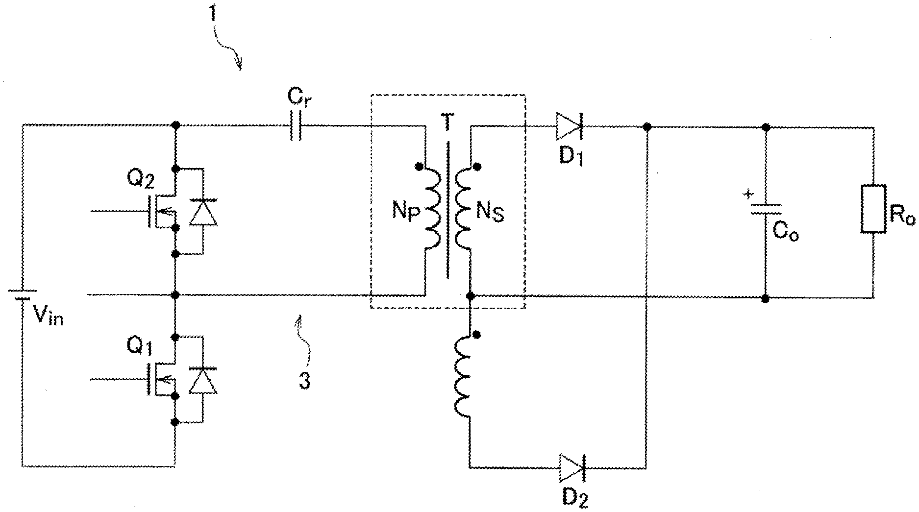
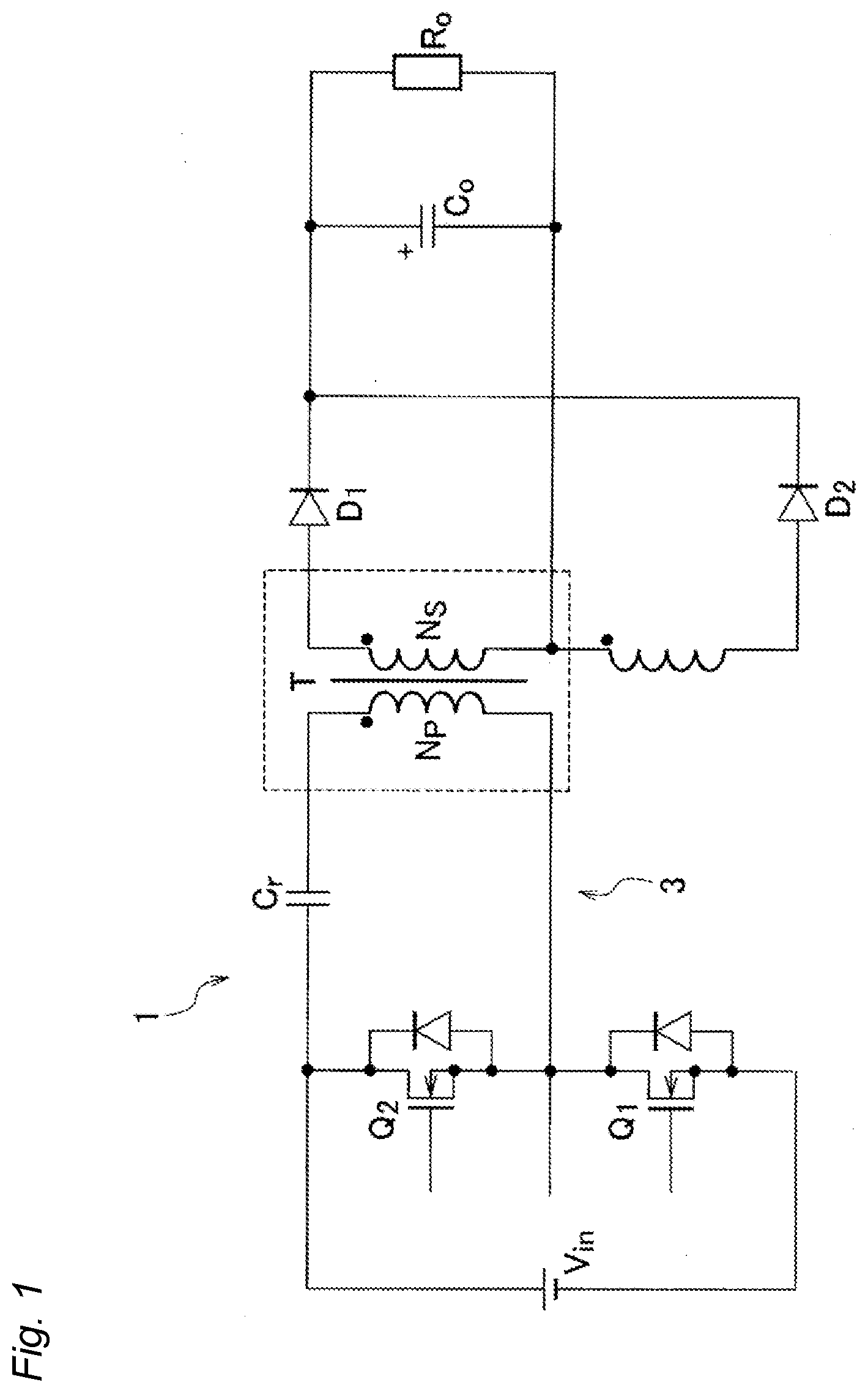
[0009] FIG. 1 is a circuit diagram showing a DC-DC converter utilizing a planar transformer according to an embodiment of the present invention;
[0010] FIG. 2A shows an exploded perspective view of the planar transformer forming the transformer shown in FIG. 1;
[0011] FIG. 2B shows a side view of the planar transformer shown in FIG. 1;
[0012] FIG. 2C shows a plan view of the planar transformer shown in FIG. 1;
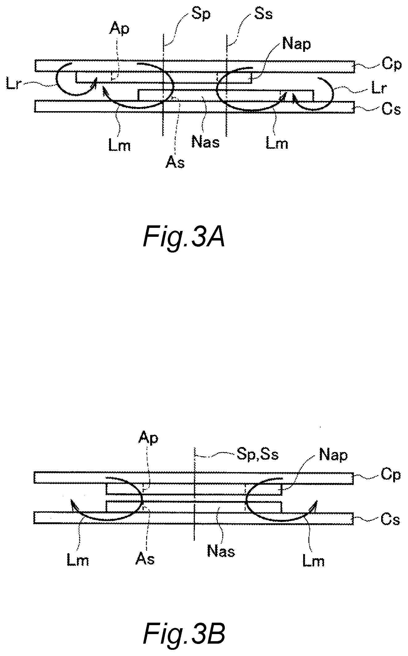
[0013] FIG. 3A is an explanatory diagram showing leakage inductance and excitation inductance generated in planar air core coils on the primary side and secondary side of the planar transformer having an arrangement shown in FIG. 2;
[0014] FIG. 3B is an explanatory diagram showing the leakage inductance and the excitation inductance generated in the primary side and secondary side planar air core coils opposed to each other;
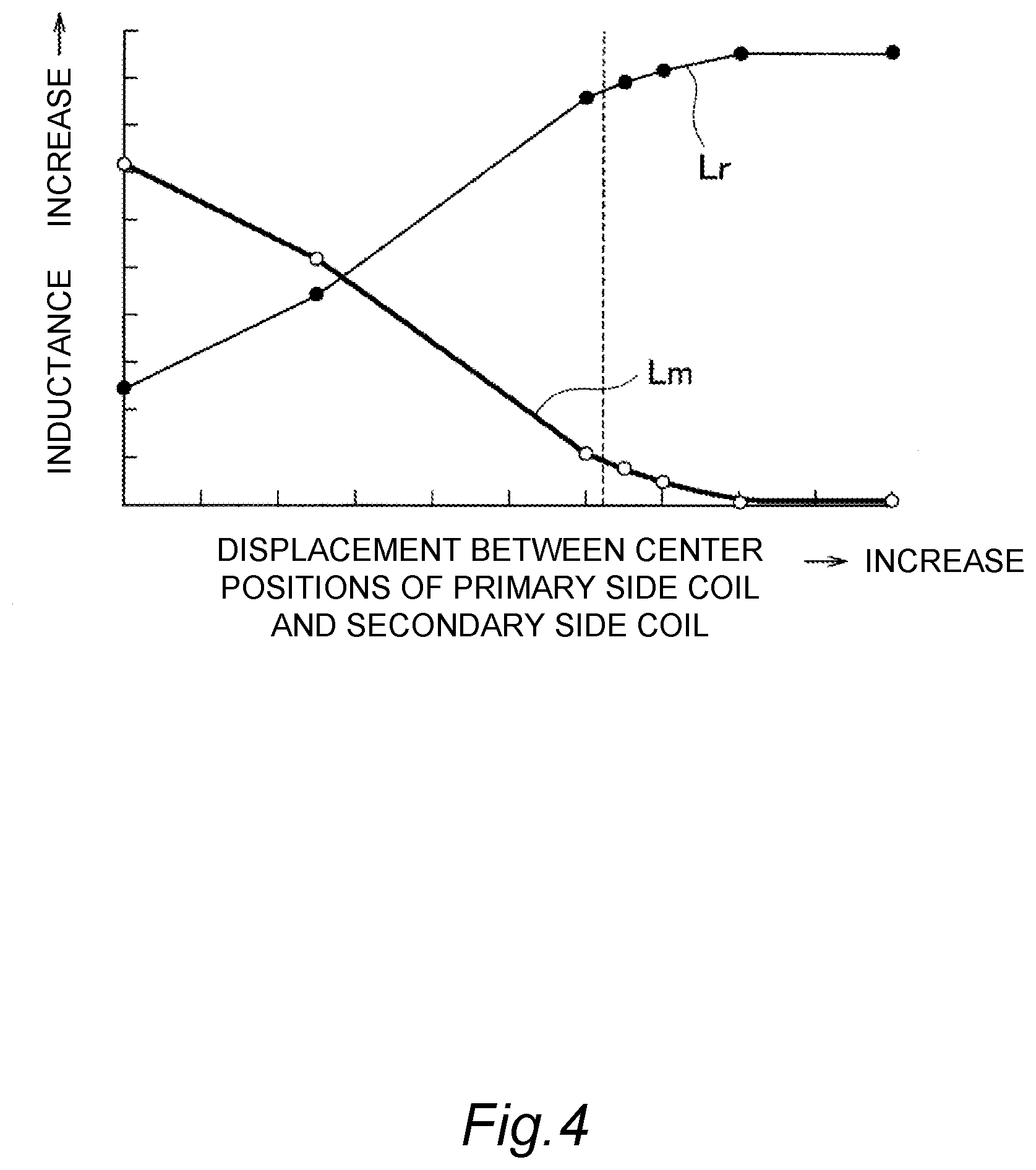
[0015] FIG. 4 is a graph showing correlation between intensities of leakage inductance and excitation inductance generated in the primary side and secondary side planar air core coils shown in FIG. 2 and a displaced distance between winding center axes of both planar air core coils;
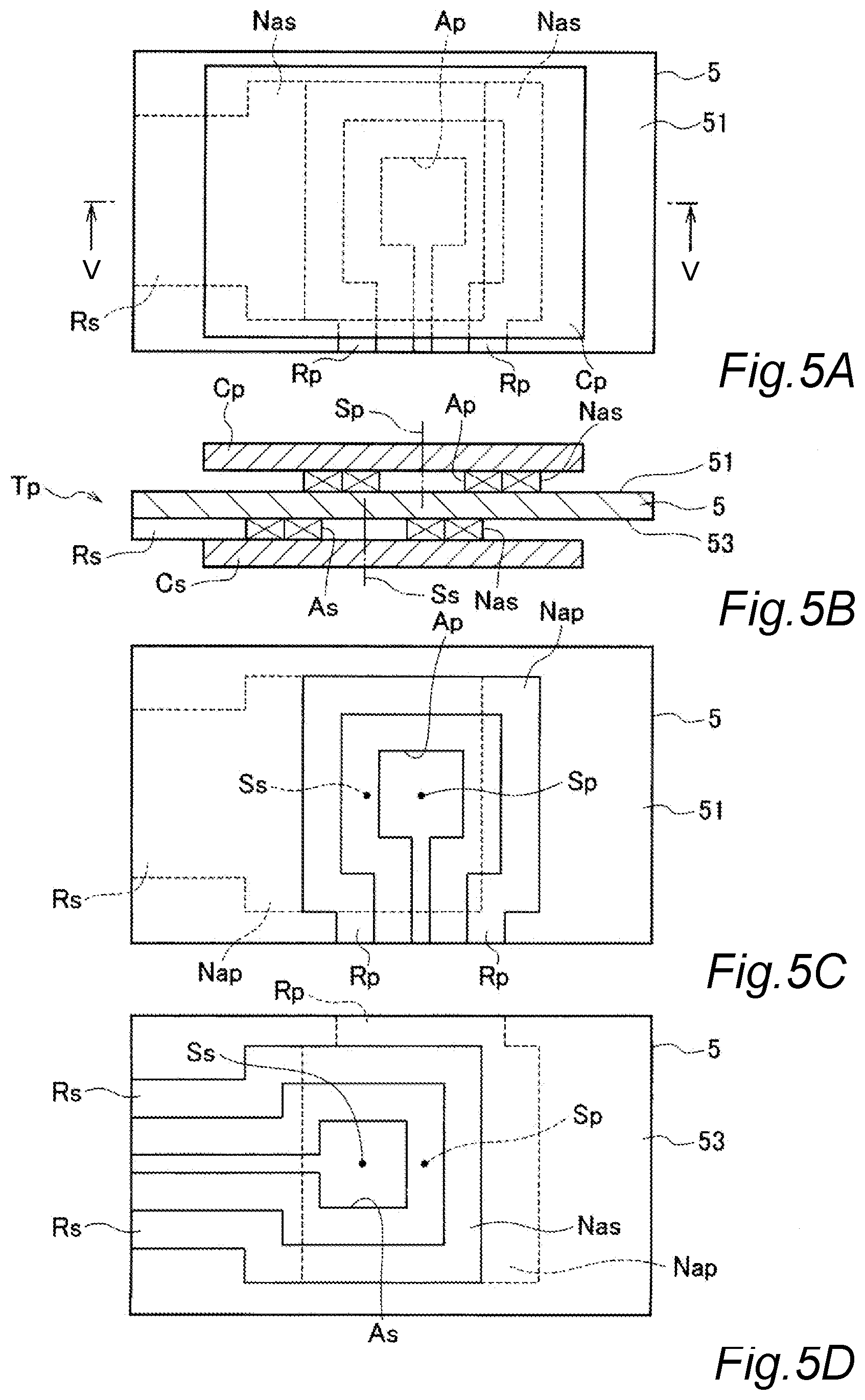
[0016] FIG. 5A shows a plan view of the planar transformer used as the transformer shown in FIG. 1;
[0017] FIG. 5B shows a sectional view taken along line I-I in FIG. 5A;
[0018] FIG. 5C shows a plan view showing a front surface side of a substrate formed with a primary side planar core;
[0019] FIG. 5D shows a plan view showing a back surface side of the substrate formed with a secondary side planar core; and
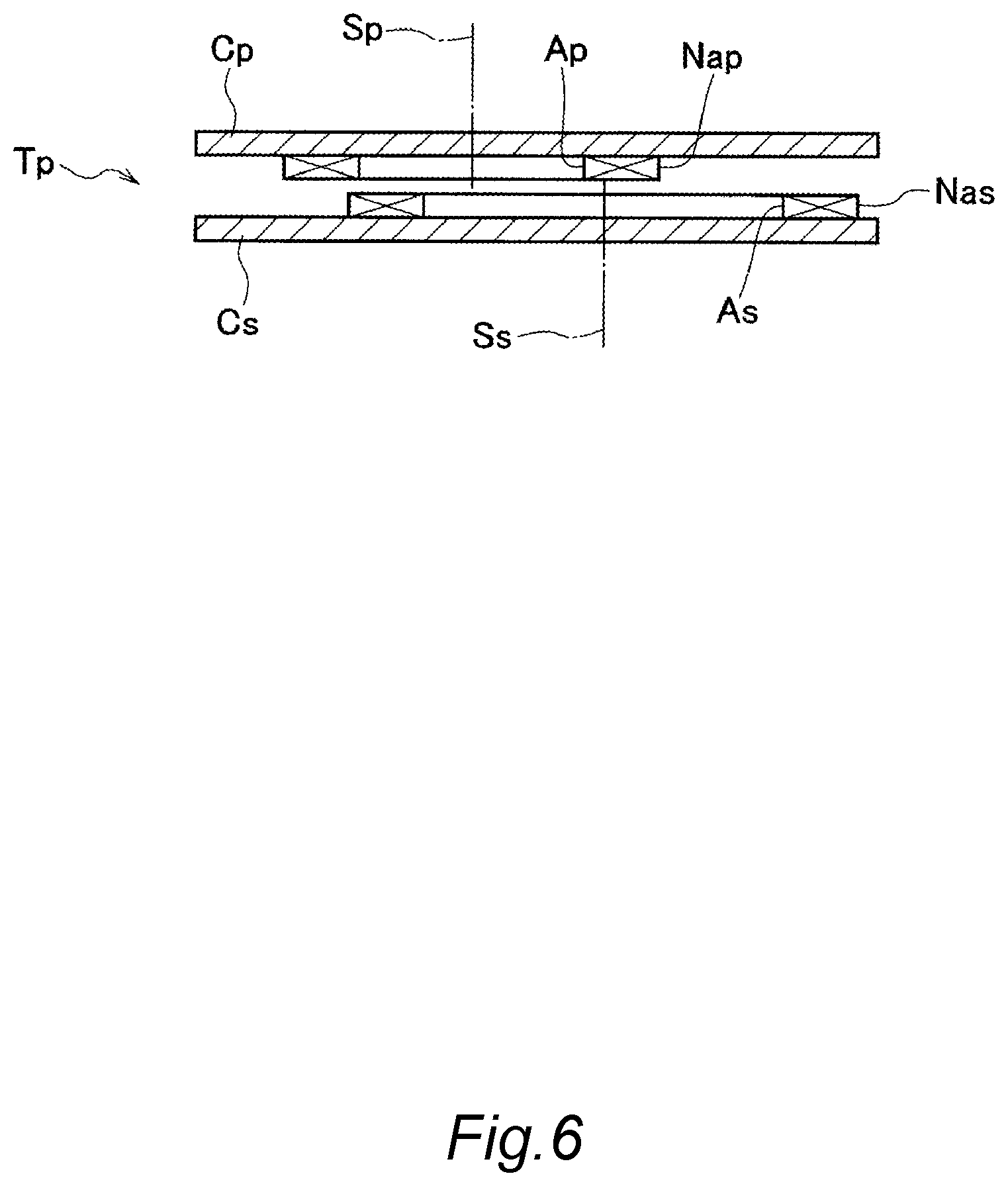
[0020] FIG. 6 is a sectional view of the planar transformer used as the transformer shown in FIG. 1, in which the planar air core coils on the primary side and the secondary side have different sizes.
DETAILED DESCRIPTION
[0021] An embodiment of the present invention will be described below with reference to the drawings. FIG. 1 is a circuit diagram showing DC-DC converter utilizing a planar transformer according to an embodiment of the present invention.
[0022] A DC-DC converter 1 according to this embodiment shown in FIG. 1 is an isolated DC-DC converter in which an asymmetrical half-bridge LLC converter 3 is used on the primary side of a transformer T.
[0023] In the DC-DC converter 1, direct-current voltage Vin input to the primary side is converted to alternating current by switching by semiconductor devices Q1 and Q2, which are formed with MOSFET, etc., of the LLC converter 3, the voltage of the alternating current is increased between coils Np and Ns on the primary side and the secondary side of the transformer T, and thereafter, the alternating current is returned to the direct current by rectifier Diodes D1 and D2 and a smoothing capacitor Co and supplied to a load Ro on the secondary side.
[0024] At this time, the semiconductor devices Q1 and Q2 are switched on and off alternately at the period of resonance frequency of series resonant circuit of the leakage inductance of the primary side coil Np and a resonant capacitor Cr, and thereby, it is possible to suppress switching loss at the LLC converter 3 and to increase the direct-current voltage Vin at a high efficiency.
[0025] The DC-DC converter 1 is configured with a resonant circuit, and the semiconductor devices Q1 and Q2 are switched on and off at a high frequency ("high frequency" in this context is equal to or higher than 1 MHz). In addition, in order to establish the resonant circuit at the high frequency, very low excitation inductance (for example, when driven at 2 MHz, 0.8 pH) and large leakage inductance (for example, when driven at 2 MHz, 1.1 pH) are required.
[0026] Thus, in the DC-DC converter 1 of this embodiment, a planar transformer is employed as the transformer T. A configuration of the planar transformer will be described below with reference to FIGS. 2A to 2C. FIG. 2A shows an exploded perspective view of the planar transformer forming the transformer T, FIG. 2B is a side view of the planar transformer, and FIG. 2C is a plan view of the planar transformer.
[0027] A planar transformer Tp in an example shown in FIG. 2A has a primary side planar core Cp made of magnetic material, a primary side planar air core coil Nap made of metal stacked on the primary side planar core Cp, a secondary side planar core Cs made of magnetic material, and a secondary side planar air core coil Nas made of metal stacked on the secondary side planar core Cs.
[0028] The primary side planar air core coil Nap and the secondary side planar air core coil Nas are formed to have ring shapes having the same diameter and are arranged non-coaxially. In addition, the primary side planar core Cp and the secondary side planar core Cs are formed to have rectangular shapes having the same size. The primary side planar core Cp and the secondary side planar core Cs have external shapes larger than the outer diameters of the primary side planar air core coil Nap and the secondary side planar air core coil Nas.
[0029] As shown in FIG. 2B, the primary side planar core Cp is arranged so as to oppose with the secondary side planar core Cs such that a space is formed therebetween. The primary side planar air core coil Nap and the secondary side planar air core coil Nas are respectively stacked on mutually facing surfaces of the primary side planar core Cp and the secondary side planar core Cs.
[0030] The primary side planar air core coil Nap and the secondary side planar air core coil Nas are arranged such that a gap is formed therebetween in the direction of the space between the primary side planar core Cp and the secondary side planar core Cs, in other words, in the respective axial directions of winding center axes Sp and Ss. In addition, the primary side planar air core coil Nap and the secondary side planar air core coil Nas are arranged such that respective positions of the winding center axes Sp and Ss are displaced from each other in the radial direction orthogonal to the winding center axes Sp and Ss such that respective air cores Ap and As are partially overlapped.
[0031] By having such an arrangement, as shown in FIG. 2C, the primary side planar air core coil Nap is provided with a facing portion Fp at which the primary side planar air core coil Nap overlaps with the secondary side planar air core coil Nas in the radial direction of the winding center axis Sp and a non-facing portion NFp positioned at the outer side of the secondary side planar air core coil Nas.
[0032] Similarly, the secondary side planar air core coil Nas is provided with a facing portion Fs at which the secondary side planar air core coil Nas overlaps with the primary side planar air core coil Nap in the radial direction of the winding center axis Ss and a non-facing portion NFs positioned at the outer side of the primary side planar air core coil Nap.
[0033] In each of FIGS. 2A to 2C, illustrations of terminal portions of the respective planar air core coils Nap and Nas are omitted.
[0034] As described above, by arranging the primary side planar air core coil Nap and the secondary side planar air core coil Nas so as to be displaced from each other in the radial direction of the winding center axes Sp and Ss, as shown in an explanatory diagram in FIG. 3A, excitation inductance Lm is generated at the facing portions Fp and Fs and leakage inductance Lr is generated at the non-facing portions NFp and NFs between both planar air core coils Nap and Nas.
[0035] If the primary side planar air core coil Nap and the secondary side planar air core coil Nas are arranged such that the winding center axes Sp and Ss coincide in the radial direction, as shown in an explanatory diagram in FIG. 3B, essentially only the excitation inductance Lm is generated at the facing portions Fp and Fs between the both planar air core coils Nap and Nas.
[0036] Therefore, as shown in FIG. 3A, the planar transformer Tp, in which the winding center axis Sp of the primary side planar air core coil Nap and the winding center axis Ss of the secondary side planar air core coil Nas are mutually displaced, is more suitable as the transformer T, in which the leakage inductance of the primary side coil Np is in series resonance with the resonant capacitor Cr in the LLC converter 3 shown in FIG. 1, than the planar transformer Tp shown in FIG. 3B, in which the winding center axis Sp of the primary side planar air core coil Nap is arranged coaxially with the winding center axis Ss of the secondary side planar air core coil Nas.
[0037] In the planar transformer Tp shown in FIG. 3A, as shown in a graph in FIG. 4, as a displaced distance between the primary side planar air core coil Nap and the secondary side planar air core coil Nas is increased, the leakage inductance Lr generated between them is increased, and the excitation inductance Lm is decreased. The displacement between the primary side planar air core coil Nap and the secondary side planar air core coil Nas means the displacement between the winding centers of the both coils.
[0038] Thus, as the transformer T shown in FIG. 1, there is provided the planar transformer Tp having the displaced distance between the both planar air core coils Nap and Nas on the primary side and secondary side shown in FIG. 3A so as to cause the leakage inductance Lr large enough to cause series resonance with the resonant capacitor Cr shown in FIG. 1 and the excitation inductance Lm large enough to satisfy a coupling coefficient required between the coils Np and Ns on the primary side and secondary side shown in FIG. 1.
[0039] A magnetic coupling between the primary side planar air core coil Nap and the secondary side planar air core coil Nas can be achieved when at least a part of the coils face each other even if the air cores Ap and As are not facing each other. Therefore, the displaced distance between the both planar air core coils Nap and Nas on the primary side and secondary side required to achieve desired leakage inductance Lr cab be set within a range up to the distance at which at least the outer edges of the both coils are overlapped with each other.
[0040] Next, a specific configuration of the planar transformer Tp used as the transformer T shown in FIG. 1 will be described with reference to FIGS. 5A to 5D. FIG. 5A is a plan view of the planar transformer Tp, FIG. 5B is a sectional view taken along the line V-V in FIG. 5A, FIG. 5C is a plan view showing a front surface side of a substrate formed with the primary side planar core, and FIG. 5D is a plan view showing a back surface side of the substrate formed with the secondary side planar core.
[0041] As shown in FIG. 5B, which is the sectional view of FIG. 5A taken along the line I-I, the planar transformer Tp of this embodiment shown in FIG. 5A has a substrate 5 in which the primary side planar air core coil Nap and the secondary side planar air core coil Nas are formed on a front surface 51 and a back surface 53, respectively. The substrate 5 is formed to have a rigid structure from insulating resin materials such as glass epoxy, etc., for example.
[0042] In the primary side planar air core coil Nap formed on the front surface 51 of the substrate 5, terminal parts Rp are provided on both ends of a conductor, which is looped in a square shape as shown in FIG. 5C, so as to extend to the long side of the front surface 51. On the other hand, in the secondary side planar air core coil Nas formed on the back surface 53 of the substrate 5 as shown in FIG. 5B, terminal parts Rs are provided on both ends of the conductor, which has the same shape as the primary side planar air core coil Nap that is looped in a square shape as shown in FIG. 5D, so as to extend to the short side of the back surface 53.
[0043] As described above, the terminal parts Rp of the primary side planar air core coil Nap and the terminal parts Rs of the secondary side planar air core coil Nas are arranged so as not to be overlapped with each other, and thereby, both of the terminal parts Rp and Rs are prevented from configuring a part of the magnetic circuit.
[0044] With the DC-DC converter 1 of this embodiment, because the planar transformer Tp configured as described above is used as the transformer T of the LLC converter 3, it is possible to increase the leakage inductance Lr generated in the primary side planar air core coil Nap and the secondary side planar air core coil Nas by increasing the displaced distance between both of the planar air core coils Nap and Nas.
[0045] In this example, the displacement between the primary side planar air core coil Nap and the secondary side planar air core coil Nas also means the displacement between the winding centers of the both coils.
[0046] In this example, it is also possible to drive the LLC converter 3 at the high frequency by generating, in the planar transformer Tp, the leakage inductance Lr that is large enough to cause the series resonance with the resonant capacitor Cr having the large capacity in accordance with the semiconductor devices Q1 and Q2 that undergo switching at the high frequency.
[0047] Furthermore, because the leakage inductance Lr generated in the primary side planar air core coil Nap and the secondary side planar air core coil Nas can be adjusted by the displaced distance between both of the planar air core coils Nap and Nas, it is possible to eliminate necessity of a highly accurate processing of the structure of the planar transformer Tp including the primary side planar core Cp and the secondary side planar core Cs.
[0048] In addition, the primary side planar core Cp and the secondary side planar core Cs do not have center poles to be inserted into the air cores Ap and As of the primary side planar air core coil Nap and the secondary side planar air core coil Nas. Therefore, both of the planar cores Cp and Cs can be arranged so as to oppose with each other so as to sandwich the air cores Ap and As of the primary side and secondary side planar air core coils Nap and Nas such that the space is formed therebetween in the axial direction of the respective winding center axes Sp and Ss of the planar air core coils Nap and Nas.
[0049] Therefore, in the planar transformer Tp of this embodiment, the magnetic flux passing through the primary side planar air core coil Nap and the secondary side planar air core coil Nas is prevented from being focused to the primary side planar core Cp and the secondary side planar core Cs.
[0050] Thus, in the non-facing portions NFp and NFs of the primary side planar air core coil Nap and the secondary side planar air core coil Nas shown in FIG. 2C, it is possible to surely generate the leakage inductance Lr of the intensity corresponding to the displaced distance between both of the planar air core coils Nap and Nas.
[0051] However, as long as it is possible to generate the leakage inductance Lr of the required intensity, the center poles to be inserted into the air cores Ap and As of the primary side and secondary side planar air core coils Nap and Nas may be provided in the primary side planar core Cp and the secondary side planar core Cs, and the primary side planar core Cp and the secondary side planar core Cs may be configured with an EE core and an EI core.
[0052] Furthermore, according to the DC-DC converter 1 of this embodiment, the primary side planar core Cp and the secondary side planar core Cs of the planar transformer Tp are formed to have the external shape that is larger than the outer diameters of the primary side planar air core coil Nap and the secondary side planar air core coil Nas.
[0053] By doing so, the leakage magnetic flux generated in the primary side planar air core coil Nap and the secondary side planar air core coil Nas can be retained in the planar transformer Tp, and thereby, it is possible to efficiently configure the leakage inductance Lr of the planar transformer Tp.
[0054] However, as long as it is possible to generate the leakage inductance Lr of the required intensity by completely covering magnetic path of the leakage magnetic flux generated in the primary side planar air core coil Nap and the secondary side planar air core coil Nas, the primary side planar core Cp and the secondary side planar core Cs may be formed to have the external shape that is smaller than the outer diameters of the primary side planar air core coil Nap and the secondary side planar air core coil Nas.
[0055] In addition, in this embodiment, the primary side planar air core coil Nap and the secondary side planar air core coil Nas of the planar transformer Tp are formed to have the same shape except for the respective terminal parts Rp and Rs. However, as shown in a sectional view in FIG. 6 for example, the planar air core coils Nap and Nas may have different sizes on the primary side and the secondary side, or the planar air core coils Nap and Nas may have different number of turns on the primary side and the secondary side.
[0056] The primary side planar air core coil Nap and the secondary side planar air core coil Nas may be formed by an etching process, etc., and thereby, it is possible to perform the processing with high positional accuracy. In a case in which such a processing is performed, a reference part (for example, a through hole) may be formed at somewhere in the substrate 5.
[0057] By doing so, when the secondary side planar air core coil Nas is to be formed, it is possible to achieve a high displacement accuracy between the primary side planar air core coil Nap and the secondary side planar air core coil Nas by performing the processing such that the winding center of the planar air core coil Nas is displaced from the reference part by a predetermined distance.
[0058] The present invention is not limited to the transformer of an isolated DC-DC converter utilizing an asymmetrical half-bridge LLC converter, and the present invention can be widely applied to transformers of various types that are used in areas utilizing the leakage inductance.
[0059] Embodiments of the present invention were described above, the above embodiments are merely examples of applications of this invention, and the technical scope of this invention is not limited to the specific constitutions of the above embodiments.
[0060] An aspect of the present invention can be utilized in transformers of various types that are used in areas utilizing the leakage inductance. [0061] 1: DC-DC converter [0062] 3: LLC converter [0063] 5: substrate (insulating substrate) [0064] 51: substrate front surface (first surface) [0065] 53: substrate back surface (second surface) [0066] Ap: air core of primary side planar air core coil [0067] As: air core of secondary side planar air core coil [0068] Co: smoothing capacitor [0069] Cp: primary side planar core [0070] Cr: resonant capacitor [0071] Cs: secondary side planar core [0072] D1, D2: rectifier Diode [0073] Fp, Fs: facing portion [0074] Lm: excitation inductance [0075] Lr: leakage inductance [0076] Nap: primary side planar air core coil [0077] Nas: secondary side planar air core coil [0078] NFp, NFs: non-facing portion [0079] Np: primary side coil [0080] Ns: secondary side coil [0081] Q1, Q2: semiconductor device [0082] Ro: load [0083] Rp: terminal part of primary side planar air core coil [0084] Rs: terminal part of secondary side planar air core coil [0085] Sp: winding center axis of primary side planar air core coil [0086] Ss: winding center axis of secondary side planar air core coil [0087] Tp: planar transformer [0088] Vin: direct-current voltage
* * * * *
D00000
D00001
D00002
D00003
D00004
D00005
D00006
XML
uspto.report is an independent third-party trademark research tool that is not affiliated, endorsed, or sponsored by the United States Patent and Trademark Office (USPTO) or any other governmental organization. The information provided by uspto.report is based on publicly available data at the time of writing and is intended for informational purposes only.
While we strive to provide accurate and up-to-date information, we do not guarantee the accuracy, completeness, reliability, or suitability of the information displayed on this site. The use of this site is at your own risk. Any reliance you place on such information is therefore strictly at your own risk.
All official trademark data, including owner information, should be verified by visiting the official USPTO website at www.uspto.gov. This site is not intended to replace professional legal advice and should not be used as a substitute for consulting with a legal professional who is knowledgeable about trademark law.