Camera Optical Lens
Chen; Jiekang ; et al.
U.S. patent application number 16/675248 was filed with the patent office on 2020-07-02 for camera optical lens. The applicant listed for this patent is AAC Optics Solutions Pte. Ltd.. Invention is credited to Jiekang Chen, Yanmei Wang, Lei Zhang, Yang Zhang.
| Application Number | 20200209558 16/675248 |
| Document ID | / |
| Family ID | 71121943 |
| Filed Date | 2020-07-02 |


| United States Patent Application | 20200209558 |
| Kind Code | A1 |
| Chen; Jiekang ; et al. | July 2, 2020 |
CAMERA OPTICAL LENS
Abstract
The present disclosure relates to the field of optical lenses and provides a camera optical lens. The camera optical lens includes, from an object side to an image side: a first lens made of a plastic material; a second lens made of a plastic material; a third lens made of a plastic material; a fourth lens made of a plastic material; a fifth lens made of a glass material; a sixth lens made of a plastic material; and a seventh lens made of a plastic material. The camera optical lens satisfies following conditions: 1.51f1/f2.50; 1.70n52.20; -2.00f3/f42.00; -10.00(R13+R14)/(R13-R14)10.00; and 0.01d9/TTL0.20. The camera optical lens can achieve a high imaging performance while obtaining a low TTL.
| Inventors: | Chen; Jiekang; (Shenzhen, CN) ; Zhang; Lei; (Shenzhen, CN) ; Wang; Yanmei; (Shenzhen, CN) ; Zhang; Yang; (Shenzhen, CN) | ||||||||||
| Applicant: |
|
||||||||||
|---|---|---|---|---|---|---|---|---|---|---|---|
| Family ID: | 71121943 | ||||||||||
| Appl. No.: | 16/675248 | ||||||||||
| Filed: | November 6, 2019 |
| Current U.S. Class: | 1/1 |
| Current CPC Class: | G02B 1/041 20130101; G02B 9/64 20130101; G02B 13/0045 20130101 |
| International Class: | G02B 13/00 20060101 G02B013/00; G02B 9/64 20060101 G02B009/64; G02B 1/04 20060101 G02B001/04 |
Foreign Application Data
| Date | Code | Application Number |
|---|---|---|
| Dec 27, 2018 | CN | 201811614500.9 |
| Dec 27, 2018 | CN | 201811614541.8 |
Claims
1. A camera optical lens, comprising, from an object side to an image side in sequence: a first lens, a second lens, a third lens, a fourth lens, a fifth lens, a sixth lens and a seventh lens, wherein the camera optical lens satisfies following conditions: 1.51f1/f2.50; 1.70n52.20; -2.00f3/f42.00; -10.00(R13+R14)/(R13-R14)10.00; and 0.01d9/TTL0.20, where f denotes a focal length of the camera optical lens; f1 denotes a focal length of the first lens; f3 denotes a focal length of the third lens; f4 denotes a focal length of the fourth lens; n5 denotes a refractive index of the fifth lens; d9 denotes an on-axis thickness of the fifth lens; TTL denotes a total optical length from an object side surface of the first lens to an image plane of the camera optical lens along an optic axis; R13 denotes a curvature radius of an object side surface of the seventh lens; and R14 denotes a curvature radius of an image side surface of the seventh lens.
2. The camera optical lens as described in claim 1, wherein the first lens is made of plastic material, the second lens is made of plastic material, the third lens is made of plastic material, the fourth lens is made of plastic material, the fifth lens is made of glass material, the sixth lens is made of plastic material and the seventh lens made of a plastic material.
3. The camera optical lens as described in claim 1, further satisfying following conditions: 1.51f1/f2.25; 1.70n52.15; -1.99f3/f42.00; -5.30(R13+R14)/(R13-R14)5.09; and 0.01d9/TTL0.13.
4. The camera optical lens as described in claim 1, wherein the first lens has a positive refractive power, the object side surface of the first lens is convex in a paraxial region, and an image side surface of the first lens is concave in the paraxial region, and the camera optical lens further satisfies following conditions: -9.86(R1+R2)/(R1-R2)-2.11; and 0.08d1/TTL0.28, where R1 denotes a curvature radius of the object side surface of the first lens; R2 denotes a curvature radius of the image side surface of the first lens; and d1 denotes an on-axis thickness of the first lens.
5. The camera optical lens as described in claim 4, further satisfying following conditions: -6.16(R1+R2)/(R1-R2)-2.64; and 0.13d1/TTL0.22.
6. The camera optical lens as described in claim 1, wherein the second lens has a positive refractive power, and comprises an object side surface being convex in a paraxial region and an image side surface being concave in the paraxial region, and the camera optical lens further satisfies following conditions: 2.64f2/f122.69; -25.23(R3+R4)/(R3-R4)823.36; and 0.02d3/TTL0.11, where f2 denotes a focal length of the second lens; R3 denotes a curvature radius of the object side surface of the second lens; R4 denotes a curvature radius of the image side surface of the second lens; and d3 denotes an on-axis thickness of the second lens.
7. The camera optical lens as described in claim 6, further satisfying following conditions: 4.22f2/f98.15; -15.77(R3+R4)/(R3-R4)658.69; and 0.03d3/TTL0.09.
8. The camera optical lens as described in claim 1, wherein the third lens has a negative refractive power, and comprises an object side surface being convex in a paraxial region and an image side surface being concave in the paraxial region, and the camera optical lens further satisfies following conditions: -1716.80f3/f-2.86; 1.94(R5+R6)/(R5-R6)193.26; and 0.02d5/TTL0.09, where R5 denotes a curvature radius of the object side surface of the third lens; R6 denotes a curvature radius of the image side surface of the third lens; and d5 denotes an on-axis thickness of the third lens.
9. The camera optical lens as described in claim 8, further satisfying following conditions: -1073.00f3/f-3.57; 3.10(R5+R6)/(R5-R6)154.61; and 0.03d5/TTL0.07.
10. The camera optical lens as described in claim 1, wherein the fourth lens comprises an object side surface being convex in a paraxial region, and the camera optical lens further satisfies following conditions: -859.33f4/f108.45; -148.05(R7+R8)/(R7-R8)23.23; and 0.04d7/TTL0.17, where R7 denotes a curvature radius of the object side surface of the fourth lens; R8 denotes a curvature radius of an image side surface of the fourth lens; and d7 denotes an on-axis thickness of the fourth lens.
11. The camera optical lens as described in claim 10, further satisfying following conditions: -537.08f4/f86.76; -92.53(R7+R8)/(R7-R8)18.58; and 0.07d7/TTL0.13.
12. The camera optical lens as described in claim 1, wherein the fifth lens has a negative refractive power, and comprises an object side surface being convex in a paraxial region and an image side surface being concave in the paraxial region, and the camera optical lens further satisfies following conditions: -7.13f5/f-1.41; and 2.27(R9+R10)/(R9-R10)8.49, where f5 denotes a focal length of the fifth lens; R9 denotes a curvature radius of the object side surface of the fifth lens; R10 denotes a curvature radius of the image side surface of the fifth lens; and d9 denotes an on-axis thickness of the fifth lens.
13. The camera optical lens as described in claim 12, further satisfying following conditions: -4.46f5/f-1.76; and 3.63(R9+R10)/(R9-R10)6.79.
14. The camera optical lens as described in claim 1, wherein the sixth lens has a positive refractive power, and comprises an object side surface being convex in a paraxial region and an image side surface being convex in the paraxial region, and the camera optical lens further satisfies following conditions: 0.28f6/f1.07; -1.68(R11+R12)/(R11-R12)-0.44; and 0.04d11/TTL0.14, where f6 denotes a focal length of the sixth lens; R11 denotes a curvature radius of the object side surface of the sixth lens; R12 denotes a curvature radius of the image side surface of the sixth lens; and d11 denotes an on-axis thickness of the sixth lens.
15. The camera optical lens as described in claim 14, further satisfying following conditions: 0.45f6/f0.85; -1.05(R11+R12)/(R11-R12)-0.55; and 0.07d11/TTL0.12.
16. The camera optical lens as described in claim 1, wherein the seventh lens has a negative refractive power, the object side surface of the seventh lens is concave in a paraxial region, and the image side surface of the seventh lens is concave in the paraxial region, and the camera optical lens further satisfies following conditions: -1.74f7/f-0.46; and 0.04d13/TTL0.11, where f7 denotes a focal length of the seventh lens; and d13 denotes an on-axis thickness of the seventh lens.
17. The camera optical lens as described in claim 16, further satisfying following conditions: -1.09f7/f-0.57; and 0.06d13/TTL0.09.
18. The camera optical lens as described in claim 1, wherein the total optical length TTL of the camera optical lens is smaller than or equal to 6.84 mm.
19. The camera optical lens as described in claim 18, wherein the total optical length TTL of the camera optical lens is smaller than or equal to 6.53 mm.
20. The camera optical lens as described in claim 1, wherein an F number of the camera optical lens is smaller than or equal to 1.47.
Description
TECHNICAL FIELD
[0001] The present disclosure relates to the field of optical lens, and more particularly, to a camera optical lens suitable for handheld terminal devices, such as smart phones and digital cameras, and imaging devices, such as monitors and PC lenses.
BACKGROUND
[0002] With the emergence of smart phones in recent years, the demand for miniature camera lens is increasing day by day, but in general the photosensitive devices of camera lens are nothing more than Charge Coupled Device (CCD) or Complementary Metal-Oxide Semiconductor Sensor (CMOS sensor), and as the progress of the semiconductor manufacturing technology makes the pixel size of the photosensitive devices become smaller, plus the current development trend of electronic products towards better functions and thinner and smaller dimensions, miniature camera lenses with good imaging quality therefore have become a mainstream in the market. In order to obtain better imaging quality, the lens that is traditionally equipped in mobile phone cameras adopts a three-piece or four-piece lens structure. Also, with the development of technology and the increase of the diverse demands of users, and as the pixel area of photosensitive devices is becoming smaller and smaller and the requirement of the system on the imaging quality is improving constantly, the five-piece, six-piece and seven-piece lens structures gradually appear in lens designs. There is an urgent need for ultra-thin, wide-angle camera lenses with good optical characteristics and fully corrected chromatic aberration.
BRIEF DESCRIPTION OF DRAWINGS
[0003] Many aspects of the exemplary embodiment can be better understood with reference to the following drawings. The components in the drawings are not necessarily drawn to scale, the emphasis instead being placed upon clearly illustrating the principles of the present disclosure. Moreover, in the drawings, like reference numerals designate corresponding parts throughout the several views.
[0004] FIG. 1 is a schematic diagram of a structure of a camera optical lens in accordance with Embodiment 1 of the present disclosure;
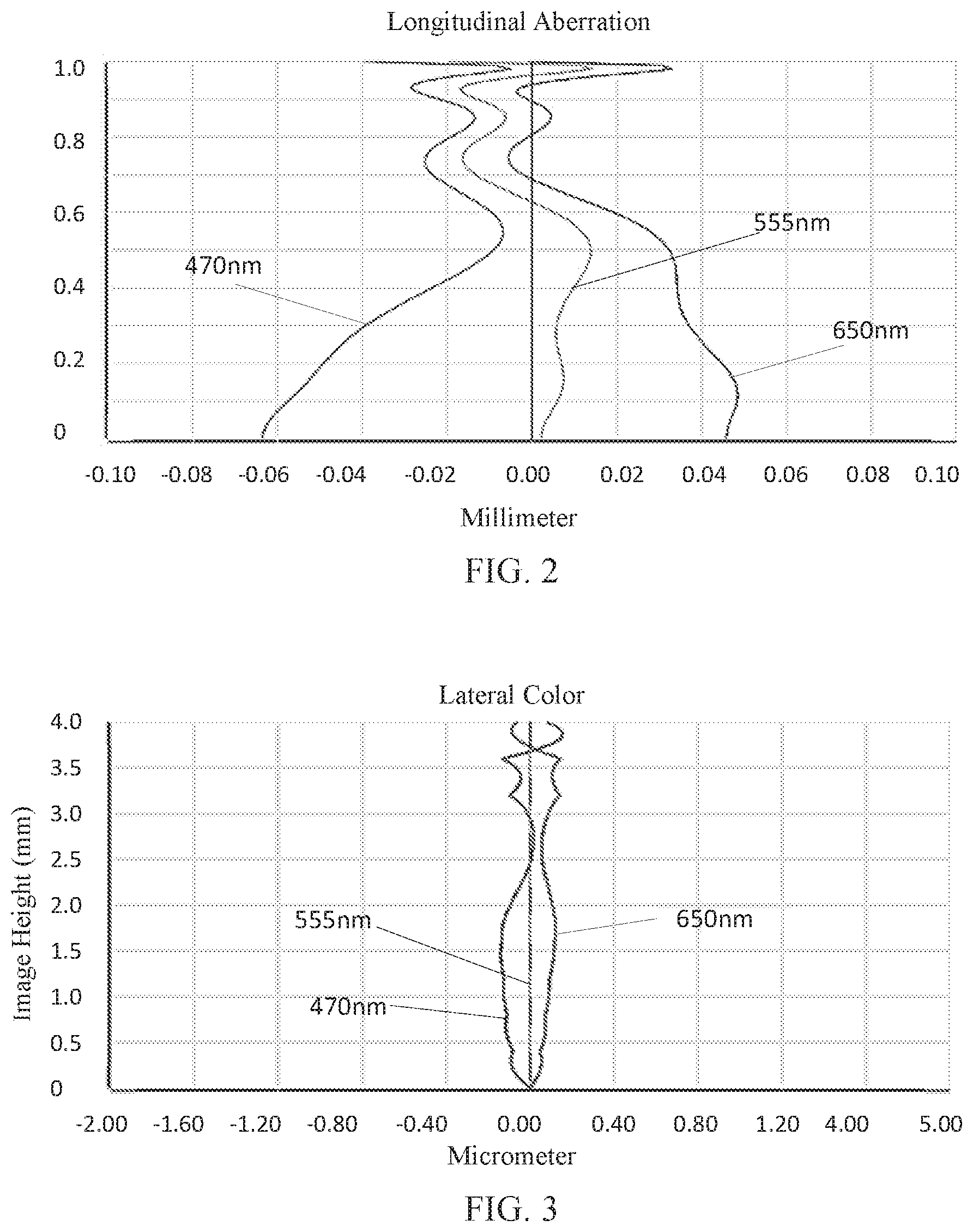
[0005] FIG. 2 is a schematic diagram of a longitudinal aberration of the camera optical lens shown in FIG. 1;
[0006] FIG. 3 is a schematic diagram of a lateral color of the camera optical lens shown in FIG. 1;
[0007] FIG. 4 is a schematic diagram of a field curvature and a distortion of the camera optical lens shown in FIG. 1;
[0008] FIG. 5 is a schematic diagram of a structure of a camera optical lens in accordance with Embodiment 2 of the present disclosure;
[0009] FIG. 6 is a schematic diagram of a longitudinal aberration of the camera optical lens shown in FIG. 5;
[0010] FIG. 7 is a schematic diagram of a lateral color of the camera optical lens shown in FIG. 5;
[0011] FIG. 8 is a schematic diagram of a field curvature and a distortion of the camera optical lens shown in FIG. 5;
[0012] FIG. 9 is a schematic diagram of a structure of a camera optical lens in accordance with Embodiment 3 of the present disclosure;
[0013] FIG. 10 is a schematic diagram of a longitudinal aberration of the camera optical lens shown in FIG. 9;
[0014] FIG. 11 is a schematic diagram of a lateral color of the camera optical lens shown in FIG. 9; and
[0015] FIG. 12 is a schematic diagram of a field curvature and a distortion of the camera optical lens shown in FIG. 9.
DESCRIPTION OF EMBODIMENTS
[0016] The present disclosure will hereinafter be described in detail with reference to several exemplary embodiments. To make the technical problems to be solved, technical solutions and beneficial effects of the present disclosure more apparent, the present disclosure is described in further detail together with the figure and the embodiments. It should be understood the specific embodiments described hereby is only to explain the disclosure, not intended to limit the disclosure.
Embodiment 1
[0017] Referring to FIG. 1, the present disclosure provides a camera optical lens 10. FIG. 1 shows the camera optical lens 10 according to Embodiment 1 of the present disclosure. The camera optical lens 10 includes 7 lenses. Specifically, the camera optical lens 10 includes, from an object side to an image side, an aperture S1, a first lens L1, a second lens L2, a third lens L3, a fourth lens L4, a fifth lens L5, a sixth lens L6 and a seventh lens L7. An optical element such as an optical filter GF can be arranged between the seventh lens L7 and an image plane Si.
[0018] The first lens L1 is made of a plastic material, the second lens L2 is made of a plastic material, the third lens L3 is made of a plastic material, the fourth lens L4 is made of a plastic material, the fifth lens L5 is made of a glass material, the sixth lens L6 is made of a plastic material, and the seventh lens L7 is made of a plastic material.
[0019] Here, a focal length of the camera optical lens 10 is defined as f, and a focal length of the first lens L1 is defined as f1. The camera optical lens 10 should satisfy a condition of 1.51f1/f2.50, which specifies a ratio of the focal length f1 of the first lens L1 and the focal length f of the camera optical lens 10. If the lower limit of the specified value is exceeded, although it would facilitate development of ultra-thin lenses, the positive refractive power of the first lens L1 will be too strong, and thus it is difficult to correct the problem like an aberration and it is also unfavorable for development of wide-angle lenses. On the contrary, if the upper limit of the specified value is exceeded, the positive refractive power of the first lens L1 would become too weak, and it is then difficult to develop ultra-thin lenses. Preferably, 1.51f1/f2.25.
[0020] A refractive index of the fifth lens L5 is defined as n5, where 1.70n52.20, which specifies the refractive index of the fifth lens L5. The refractive index within this range facilitates development of ultra-thin lenses, and also facilitates correction of the aberration. Preferably, 1.70n52.15.
[0021] A focal length of the third lens L3 is defined as f3, and a focal length of the fourth lens L4 is defined as f4. The camera optical lens 10 should satisfy a condition of -2.00f3/f42.00, which specifies a ratio of the focal length f3 of the third lens L3 and the focal length f4 of the fourth lens L4. This can effectively reduce the sensitivity of optical lens group used in the camera and further enhance the imaging quality. Preferably, -1.99f3/f42.00.
[0022] A curvature radius of an object side surface of the seventh lens L7 is defined as R13, and a curvature radius of an image side surface of the seventh lens L7 is defined as R14. The camera optical lens 10 further satisfies a condition of -10.00(R13+R14)/(R13-R14)10.00, which specifies a shape of the seventh lens L7. Out of this range, a development towards ultra-thin and wide-angle lenses would make it difficult to correct the problem like an off-axis aberration. Preferably, -5.30(R13+R14)/(R13-R14)5.09.
[0023] An on-axis thickness of the fifth lens L5 is defined as d9. A total optical length from an object side surface of the first lens L1 to an image plane of the camera optical lens 10 along an optic axis is defined as a total optical length TTL. The camera optical lens 10 further satisfies a condition of 0.01d9/TTL0.20, which specifies a ratio between the on-axis thickness of the fifth lens L5 and the TTL of the camera optical lens 10. This facilitates achieving ultra-thin lenses. Preferably, 0.01d9/TTL 0.13.
[0024] When the focal length of the camera optical lens, the focal length of the first lens, the focal length of the third lens, the focal length of the fourth lens, the refractive index of the fifth lens, the on-axis thickness of the fifth lens, the TTL, the curvature radius of the object side surface of the seventh lens and the curvature radius of the image side surface of the seventh lens satisfy the above conditions, the camera optical lens will have the advantage of high performance and satisfy the design requirement of a low TTL.
[0025] In this embodiment, the object side surface of the first lens L1 is convex in a paraxial region, an image side surface of the first lens L1 is concave in the paraxial region, and the first lens L1 has a positive refractive power.
[0026] A curvature radius of the object side surface of the first lens L1 is defined as R1, and a curvature radius of the image side surface of the first lens L1 is defined as R2. The camera optical lens 10 further satisfies a condition of -9.86(R1+R2)/(R1-R2)-2.11. This can reasonably control a shape of the first lens L1 in such a manner that the first lens L1 can effectively correct a spherical aberration of the camera optical lens. Preferably, -6.16(R1+R2)/(R1-R2)-2.64.
[0027] An on-axis thickness of the first lens L1 is defined as d1. The camera optical lens 10 further satisfies a condition of 0.08d1/TTL0.28. This facilitates achieving ultra-thin lenses. Preferably, 0.13d1/TTL0.22.
[0028] In this embodiment, an object side surface of the second lens L2 is convex in the paraxial region, an image side surface of the second lens L2 is concave in the paraxial region, and the second lens L2 has a positive refractive power.
[0029] The focal length of the camera optical lens 10 is f, and a focal length of the second lens L2 is f2. The camera optical lens 10 further satisfies a condition of 2.64f2/f122.69. By controlling the positive refractive power of the second lens L2 within the reasonable range, correction of the aberration of the optical system can be facilitated. Preferably, 4.22f2/f98.15.
[0030] A curvature radius of the object side surface of the second lens L2 is defined as R3, and a curvature radius of the image side surface of the second lens L2 is defined as R4. The camera optical lens 10 further satisfies a condition of -25.23(R3+R4)/(R3-R4)823.36, which specifies a shape of the second lens L2. Out of this range, a development towards ultra-thin and wide-angle lenses would make it difficult to correct the problem of aberration. Preferably, -15.77(R3+R4)/(R3-R4)658.69.
[0031] An on-axis thickness of the second lens L2 is defined as d3. The camera optical lens 10 further satisfies a condition of 0.02d3/TTL0.11. This facilitates achieving ultra-thin lenses. Preferably, 0.03d3/TTL0.09.
[0032] In this embodiment, an object side surface of the third lens L3 is convex in the paraxial region, an image side surface of the third lens L3 is concave in the paraxial region, and the third lens L3 has a negative refractive power.
[0033] The focal length of the camera optical lens 10 is f, and a focal length of the third lens L3 is f3. The camera optical lens 10 further satisfies a condition of -1716.80f3/f-2.86. When the condition is satisfied, the field curvature of the system can be effectively balanced for further improving the image quality. Preferably, -1073.00f3/f-3.57
[0034] A curvature radius of the object side surface of the third lens L3 is defined as R5, and a curvature radius of the image side surface of the third lens L3 is defined as R6. The camera optical lens 10 further satisfies a condition of 1.94(R5+R6)/(R5-R6)193.26. This can effectively control a shape of the third lens L3, thereby facilitating shaping of the third lens L3 and avoiding bad shaping and generation of stress due to the overly large surface curvature of the third lens L3. Preferably, 3.10(R5+R6)/(R5-R6)154.61.
[0035] An on-axis thickness of the third lens L3 is defined as d5. The camera optical lens 10 further satisfies a condition of 0.02d5/TTL0.09. This facilitates achieving ultra-thin lenses. Preferably, 0.03d5/TTL0.07.
[0036] In this embodiment, an object side surface of the fourth lens L4 is convex in the paraxial region.
[0037] The focal length of the camera optical lens 10 is f, and a focal length of the fourth lens L4 is f4. The camera optical lens 10 further satisfies a condition of -859.33f4/f108.45. The appropriate distribution of the refractive power leads to a better imaging quality and a lower sensitivity. Preferably, -537.08f4/f86.76.
[0038] A curvature radius of the object side surface of the fourth lens L4 is defined as R7, and a curvature radius of an image side surface of the fourth lens L4 is defined as R8. The camera optical lens 10 further satisfies a condition of -148.05(R7+R8)/(R7-R8)23.23, which specifies a shape of the fourth lens L4. Out of this range, a development towards ultra-thin and wide-angle lenses would make it difficult to correct the problem like an off-axis aberration. Preferably, -92.53(R7+R8)/(R7-R8)18.58.
[0039] An on-axis thickness of the fourth lens L4 is defined as d7. The camera optical lens 10 further satisfies a condition of 0.04d7/TTL0.17. This facilitates achieving ultra-thin lenses. Preferably, 0.07d7/TTL0.13.
[0040] In this embodiment, an object side surface of the fifth lens L5 is convex in the paraxial region, an image side surface of the fifth lens L5 is concave in the paraxial region, and the fifth lens L5 has a negative refractive power.
[0041] The focal length of the camera optical lens 10 is f, and a focal length of the fifth lens L5 is f5. The camera optical lens 10 further satisfies a condition of -7.13f5/f-1.41. This can effectively make a light angle of the camera lens gentle and reduce the tolerance sensitivity. Preferably, -4.46f5/f-1.76.
[0042] A curvature radius of the object side surface of the fifth lens L5 is defined as R9, and a curvature radius of the image side surface of the fifth lens L5 is defined as R10. The camera optical lens 10 further satisfies a condition of 2.27(R9+R10)/(R9-R10)8.49, which specifies a shape of the fifth lens L5. Out of this range, a development towards ultra-thin and wide-angle lenses would make it difficult to correct the problem like an off-axis aberration. Preferably, 3.63(R9+R10)/(R9-R10)6.79.
[0043] In this embodiment, an object side surface of the sixth lens L6 is convex in the paraxial region, an image side surface of the sixth lens L6 is convex in the paraxial region, and the sixth lens L6 has a positive refractive power.
[0044] The focal length of the camera optical lens 10 is f, and a focal length of the sixth lens L6 is f6. The camera optical lens 10 further satisfies a condition of 0.28f6/f1.07. The appropriate distribution of the refractive power leads to a better imaging quality and a lower sensitivity. Preferably, 0.45f6/f0.85.
[0045] A curvature radius of the object side surface of the sixth lens L6 is defined as R11, and a curvature radius of the image side surface of the sixth lens L6 is defined as R12. The camera optical lens 10 further satisfies a condition of -1.68(R11+R12)/(R11-R12)-0.44, which specifies a shape of the sixth lens L6. Out of this range, a development towards ultra-thin and wide-angle lenses would make it difficult to correct the problem like an off-axis aberration. Preferably, -1.05(R11+R12)/(R11-R12)-0.55.
[0046] A thickness on-axis of the sixth lens L6 is defined as d11. The camera optical lens 10 further satisfies a condition of 0.04d11/TTL0.14. This facilitates achieving ultra-thin lenses. Preferably, 0.07d11/TTL0.12.
[0047] In this embodiment, an object side surface of the seventh lens L7 is concave in the paraxial region and an image side surface of the seventh lens L7 is concave in the paraxial region, and has a negative refractive power.
[0048] The focal length of the camera optical lens 10 is f, and a focal length of the seventh lens L7 is f7. The camera optical lens 10 further satisfies a condition of -1.74f7/f-0.46. The appropriate distribution of the refractive power leads to a better imaging quality and a lower sensitivity. Preferably, -1.09f7/f-0.57.
[0049] An on-axis thickness of the seventh lens L7 is defined as d13. The camera optical lens 10 further satisfies a condition of 0.04d13/TTL0.11. This facilitates achieving ultra-thin lenses. Preferably, 0.06d13/TTL0.09.
[0050] In this embodiment, the total optical length TTL of the camera optical lens 10 is smaller than or equal to 6.84 mm, which is beneficial for achieving ultra-thin lenses. Preferably, the total optical length TTL of the camera optical lens 10 is smaller than or equal to 6.53 mm.
[0051] In this embodiment, an F number of the camera optical lens 10 is smaller than or equal to 1.47. The camera optical lens 10 has a large F number and a better imaging performance. Preferably, the F number of the camera optical lens 10 is smaller than or equal to 1.44.
[0052] With such design, the total optical length TTL of the camera optical lens 10 can be made as short as possible, and thus the miniaturization characteristics can be maintained.
[0053] In the following, examples will be used to describe the camera optical lens 10 of the present disclosure. The symbols recorded in each example will be described as follows. The focal length, on-axis distance, curvature radius, on-axis thickness, inflexion point position, and arrest point position are all in units of mm.
[0054] TTL: Optical length (the total optical length from the object side surface of the first lens to the image plane of the camera optical lens along the optic axis) in mm.
[0055] Preferably, inflexion points and/or arrest points can be arranged on the object side surface and/or image side surface of the lens, so as to satisfy the demand for the high quality imaging. The description below can be referred to for specific implementations.
[0056] The design information of the camera optical lens 10 in Embodiment 1 of the present disclosure is shown in Tables 1 and 2.
TABLE-US-00001 TABLE 1 R d nd vd S1 .infin. d0= -0.663 R1 2.340 d1= 1.040 nd1 1.5444 v1 55.82 R2 3.531 d2= 0.043 R3 3.309 d3= 0.460 nd2 1.6610 v2 20.53 R4 3.879 d4= 0.511 R5 7.714 d5= 0.244 nd3 1.6610 v3 20.53 R6 7.595 d6= 0.081 R7 155.126 d7= 0.560 nd4 1.5444 v4 55.82 R8 136.305 d8= 0.280 R9 3.258 d9= 0.310 nd5 1.7130 v5 53.83 R10 2.279 d10= 0.181 R11 1.862 d11= 0.520 nd6 1.5444 v6 55.82 R12 -11.838 d12= 0.589 R13 -4.136 d13= 0.473 nd7 1.5346 v7 55.69 R14 3.348 d14= 0.535 R15 .infin. d15= 0.210 ndg 1.5168 vg 64.17 R16 .infin. d16= 0.185
[0057] In the table, meanings of various symbols will be described as follows.
[0058] S1: aperture;
[0059] R: curvature radius of an optical surface, a central curvature radius for a lens;
[0060] R1: curvature radius of the object side surface of the first lens L1;
[0061] R2: curvature radius of the image side surface of the first lens L1;
[0062] R3: curvature radius of the object side surface of the second lens L2;
[0063] R4: curvature radius of the image side surface of the second lens L2;
[0064] R5: curvature radius of the object side surface of the third lens L3;
[0065] R6: curvature radius of the image side surface of the third lens L3;
[0066] R7: curvature radius of the object side surface of the fourth lens L4;
[0067] R8: curvature radius of the image side surface of the fourth lens L4;
[0068] R9: curvature radius of the object side surface of the fifth lens L5;
[0069] R10: curvature radius of the image side surface of the fifth lens L5;
[0070] R11: curvature radius of the object side surface of the sixth lens L6;
[0071] R12: curvature radius of the image side surface of the sixth lens L6;
[0072] R13: curvature radius of the object side surface of the seventh lens L7;
[0073] R14: curvature radius of the image side surface of the seventh lens L7;
[0074] R15: curvature radius of an object side surface of the optical filter GF;
[0075] R16: curvature radius of an image side surface of the optical filter GF;
[0076] d: on-axis thickness of a lens and an on-axis distance between lenses;
[0077] d0: on-axis distance from the aperture S1 to the object side surface of the first lens L1;
[0078] d1: on-axis thickness of the first lens L1;
[0079] d2: on-axis distance from the image side surface of the first lens L1 to the object side surface of the second lens L2;
[0080] d3: on-axis thickness of the second lens L2;
[0081] d4: on-axis distance from the image side surface of the second lens L2 to the object side surface of the third lens L3;
[0082] d5: on-axis thickness of the third lens L3;
[0083] d6: on-axis distance from the image side surface of the third lens L3 to the object side surface of the fourth lens L4;
[0084] d7: on-axis thickness of the fourth lens L4;
[0085] d8: on-axis distance from the image side surface of the fourth lens L4 to the object side surface of the fifth lens L5;
[0086] d9: on-axis thickness of the fifth lens L5;
[0087] d10: on-axis distance from the image side surface of the fifth lens L5 to the object side surface of the sixth lens L6;
[0088] d11: on-axis thickness of the sixth lens L6;
[0089] d12: on-axis distance from the image side surface of the sixth lens L6 to the object side surface of the seventh lens L7;
[0090] d13: on-axis thickness of the seventh lens L7;
[0091] d14: on-axis distance from the image side surface of the seventh lens L7 to the object side surface of the optical filter GF;
[0092] d15: on-axis thickness of the optical filter GF;
[0093] d16: on-axis distance from the image side surface of the optical filter GF to the image plane;
[0094] nd: refractive index of d line;
[0095] nd1: refractive index of d line of the first lens L1;
[0096] nd2: refractive index of d line of the second lens L2;
[0097] nd3: refractive index of d line of the third lens L3;
[0098] nd4: refractive index of d line of the fourth lens L4;
[0099] nd5: refractive index of d line of the fifth lens L5;
[0100] nd6: refractive index of d line of the sixth lens L6;
[0101] nd7: refractive index of d line of the seventh lens L7;
[0102] ndg: refractive index of d line of the optical filter GF;
[0103] vd: abbe number;
[0104] v1: abbe number of the first lens L1;
[0105] v2: abbe number of the second lens L2;
[0106] v3: abbe number of the third lens L3;
[0107] v4: abbe number of the fourth lens L4;
[0108] v5: abbe number of the fifth lens L5;
[0109] v6: abbe number of the sixth lens L6;
[0110] v7: abbe number of the seventh lens L7;
[0111] vg: abbe number of the optical filter GF.
[0112] Table 2 shows aspherical surface data of the camera optical lens 10 in Embodiment 1 of the present disclosure.
TABLE-US-00002 TABLE 2 Conic coefficient Aspherical surface coefficients k A4 A6 A8 A10 A12 A14 A16 R1 4.5189E-01 -3.8810E-03 -1.2874E-03 -1.2580E-03 1.0708E-03 -6.4588E-04 2.0159E-04 -3.4739E-05 R2 -4.6854E+01 -7.8583E-02 5.7118E-02 -1.9606E-02 3.8332E-03 -1.4050E-03 5.3046E-04 -7.4019E-05 R3 2.9714E+00 -1.7768E-01 1.1076E-01 -3.9910E-02 9.1168E-03 -5.0779E-03 2.5144E-03 -4.4146E-04 R4 2.6658E+00 -2.3052E-02 -2.0584E-02 7.7055E-02 -1.0068E-01 7.6434E-02 -3.2204E-02 5.7884E-03 R5 2.3940E+01 -4.4093E-02 3.7520E-02 -1.4266E-01 1.7855E-01 -1.2401E-01 4.2186E-02 -5.1537E-03 R6 -4.1525E+01 -3.8734E-02 9.6963E-02 -1.9682E-01 1.8181E-01 -1.0104E-01 3.1208E-02 -3.8764E-03 R7 2.3282E+02 -6.0542E-02 9.4727E-02 -1.1581E-01 6.6969E-02 -1.8685E-02 2.3451E-03 -8.0222E-05 R8 -2.3164E+02 -6.7334E-02 3.2517E-02 -3.3333E-02 1.3002E-02 9.0878E-04 -1.7452E-03 2.9220E-04 R9 -1.5338E+02 -8.8097E-03 -1.3517E-02 4.0123E-02 -4.2070E-02 1.8783E-02 -3.9086E-03 3.1155E-04 R10 -5.8419E+01 -1.1903E-01 5.5676E-02 1.5804E-02 -3.2499E-02 1.4369E-02 -2.6924E-03 1.8695E-04 R11 -1.1566E+01 1.2935E-02 -1.0582E-01 9.0243E-02 -4.1248E-02 9.8254E-03 -1.1577E-03 5.4423E-05 R12 1.7555E+01 8.6030E-02 -1.2840E-01 7.5950E-02 -2.5330E-02 4.7374E-03 -4.5635E-04 1.7603E-05 R13 -2.0780E-01 -1.3246E-01 4.6755E-02 -4.9078E-03 -1.9228E-04 8.5600E-05 -6.9427E-06 1.9111E-07 R14 -1.6242E+01 -7.9919E-02 3.4066E-02 -8.2629E-03 1.1700E-03 -9.6890E-05 4.3673E-06 -8.2914E-08
[0113] Here, K is a conic coefficient, and A4, A6, A8, A10, A12, A14 and A16 are aspheric surface coefficients.
[0114] IH: Image Height
y=(x.sup.2/R)/[1+{1-(k+1)(x.sup.2/R.sup.2)}.sup.1/2]+A4x.sup.4+A6x.sup.6- +A8x.sup.8+A10x.sup.10+A12x.sup.12+A14x.sup.14+A6x.sup.16 (1)
[0115] For convenience, an aspheric surface of each lens surface uses the aspheric surfaces shown in the above formula (1). However, the present disclosure is not limited to the aspherical polynomials form shown in the formula (1).
[0116] Table 3 and Table 4 show design data of inflexion points and arrest points of respective lens in the camera optical lens 10 according to Embodiment 1 of the present disclosure. R1 and R2 represent the object side surface and the image side surface of the first lens L1, R3 and R4 represent the object side surface and the image side surface of the second lens L2, R5 and R6 represent the object side surface and the image side surface of the third lens L3, R7 and R8 represent the object side surface and the image side surface of the fourth lens L4, R9 and R10 represent the object side surface and the image side surface of the fifth lens L5, R11 and R12 represent the object side surface and the image side surface of the sixth lens L6, and R13 and R14 represent the object side surface and the image side surface of the seventh lens L7. The data in the column named "inflexion point position" refers to vertical distances from inflexion points arranged on each lens surface to the optic axis of the camera optical lens 10. The data in the column named "arrest point position" refers to vertical distances from arrest points arranged on each lens surface to the optic axis of the camera optical lens 10.
TABLE-US-00003 TABLE 3 Number of Inflexion point Inflexion point inflexion points position 1 position 2 R1 1 1.595 R2 1 0.445 R3 2 0.495 0.905 R4 0 R5 2 0.525 1.295 R6 2 0.595 1.325 R7 2 0.105 1.325 R8 1 0.105 R9 2 0.515 1.905 R10 2 0.335 2.025 R11 2 0.605 1.925 R12 1 1.975 R13 1 1.435 R14 1 0.515
TABLE-US-00004 TABLE 4 Number of Arrest point arrest points position 1 R1 0 R2 1 1.315 R3 0 R4 0 R5 1 0.815 R6 1 0.885 R7 1 0.165 R8 1 0.165 R9 1 1.125 R10 1 0.745 R11 1 1.155 R12 0 R13 1 2.605 R14 1 1.105
[0117] FIG. 2 and FIG. 3 illustrate a longitudinal aberration and a lateral color of light with wavelengths of 470 nm, 555 nm and 650 nm after passing the camera optical lens 10 according to Embodiment 1. FIG. 4 illustrates a field curvature and a distortion of light with a wavelength of 555 nm after passing the camera optical lens 10 according to Embodiment 1, in which a field curvature S is a field curvature in a sagittal direction and T is a field curvature in a tangential direction.
[0118] Table 13 shows various values of Embodiments 1, 2 and 3 and values corresponding to parameters which are specified in the above conditions.
[0119] As shown in Table 13, Embodiment 1 satisfies the above conditions.
[0120] In this embodiment, the entrance pupil diameter of the camera optical lens is 3.384 mm. The image height of 1.0H is 4.00 mm. The FOV (field of view) is 78.10.degree.. Thus, the camera optical lens has a wide-angle and is ultra-thin. Its on-axis and off-axis chromatic aberrations are fully corrected, thereby achieving excellent optical characteristics.
Embodiment 2
[0121] Embodiment 2 is basically the same as Embodiment 1 and involves symbols having the same meanings as Embodiment 1, and only differences therebetween will be described in the following.
[0122] Table 5 and Table 6 show design data of a camera optical lens 20 in Embodiment 2 of the present disclosure.
TABLE-US-00005 TABLE 5 R d nd vd S1 .infin. d0= -0.615 R1 2.235 d1= 1.148 nd1 1.5444 v1 55.82 R2 4.144 d2= 0.034 R3 3.449 d3= 0.264 nd2 1.6610 v2 20.53 R4 3.436 d4= 0.542 R5 9.375 d5= 0.241 nd3 1.6610 v3 20.53 R6 5.528 d6= 0.051 R7 8.855 d7= 0.508 nd4 1.5444 v4 55.82 R8 9.098 d8= 0.170 R9 3.591 d9= 0.381 nd5 1.7040 v5 39.38 R10 2.294 d10= 0.166 R11 1.613 d11= 0.598 nd6 1.5444 v6 55.82 R12 -18.414 d12= 0.751 R13 -2.853 d13= 0.463 nd7 1.5346 v7 55.69 R14 11.361 d14= 0.535 R15 .infin. d15= 0.210 ndg 1.5168 vg 64.17 R16 .infin. d16= 0.132
[0123] Table 6 shows aspherical surface data of each lens of the camera optical lens 20 in Embodiment 2 of the present disclosure.
TABLE-US-00006 TABLE 6 Conic coefficient Aspherical surface coefficients k A4 A6 A8 A10 A12 A14 A16 R1 2.8716E-01 -2.7608E-03 5.1712E-04 -1.4816E-03 1.0568E-03 -6.1650E-04 2.1722E-04 -3.4809E-05 R2 -4.2745E+01 -6.8579E-02 5.6968E-02 -2.0177E-02 3.6222E-03 -1.3811E-03 6.1313E-04 -8.7018E-05 R3 3.1060E+00 -1.5520E-01 9.5011E-02 -3.4276E-02 9.5488E-03 -5.6263E-03 2.3236E-03 -3.2692E-04 R4 2.4468E+00 -3.6899E-02 -1.0643E-02 7.2879E-02 -1.0208E-01 7.7960E-02 -3.2129E-02 5.5694E-03 R5 2.4510E+01 -4.4429E-02 4.4788E-02 -1.4592E-01 1.8020E-01 -1.2323E-01 4.1809E-02 -5.2574E-03 R6 -7.4331E+01 -2.9112E-02 9.3395E-02 -1.9690E-01 1.8267E-01 -1.0086E-01 3.1115E-02 -3.9207E-03 R7 1.8455E+01 -7.9112E-02 1.0183E-01 -1.1709E-01 6.6559E-02 -1.8544E-02 2.4136E-03 -1.0487E-04 R8 -5.8560E+01 -6.0501E-02 2.7824E-02 -3.0958E-02 1.3020E-02 7.0053E-04 -1.7818E-03 3.2223E-04 R9 -5.3696E+01 -1.5001E-02 -1.3544E-02 4.0449E-02 -4.1840E-02 1.8815E-02 -3.9175E-03 3.0889E-04 R10 -1.7553E+01 -1.3389E-01 5.8696E-02 1.6101E-02 -3.2482E-02 1.4367E-02 -2.6940E-03 1.8655E-04 R11 -6.3918E+00 1.2208E-02 -1.0585E-01 9.0293E-02 -4.1283E-02 9.8156E-03 -1.1572E-03 5.4825E-05 R12 4.9130E+01 8.2216E-02 -1.2781E-01 7.5992E-02 -2.5327E-02 4.7372E-03 -4.5652E-04 1.7576E-05 R13 -8.4607E-01 -1.2838E-01 4.6852E-02 -4.9097E-03 -1.9297E-04 8.5480E-05 -6.9490E-06 1.9230E-07 R14 -3.5691E+01 -8.1833E-02 3.4179E-02 -8.2671E-03 1.1691E-03 -9.6932E-05 4.3725E-06 -8.1525E-08
[0124] Table 7 and table 8 show design data of inflexion points and arrest points of respective lens in the camera optical lens 20 according to Embodiment 2 of the present disclosure.
TABLE-US-00007 TABLE 7 Number of Inflexion Inflexion Inflexion Inflexion inflexion point point point point points position 1 position 2 position 3 position 4 R1 0 R2 4 0.515 0.885 1.235 1.395 R3 2 0.535 0.845 R4 0 R5 2 0.495 1.325 R6 2 0.605 1.335 R7 2 0.495 1.275 R8 2 0.395 1.625 R9 1 0.635 R10 2 0.425 2.045 R11 2 0.665 1.935 R12 4 0.285 0.525 1.955 2.375 R13 1 1.425 R14 2 0.315 2.825
TABLE-US-00008 TABLE 8 Number of Arrest point Arrest point arrest points position 1 position 2 R1 0 R2 0 R3 0 R4 0 R5 1 0.775 R6 1 0.925 R7 2 0.865 1.495 R8 1 0.685 R9 1 1.175 R10 1 0.925 R11 2 1.255 2.185 R12 0 R13 1 2.525 R14 1 0.565
[0125] FIG. 6 and FIG. 7 illustrate a longitudinal aberration and a lateral color of light with wavelengths of 470 nm, 555 nm and 650 nm after passing the camera optical lens 20 according to Embodiment 2. FIG. 8 illustrates a field curvature and a distortion of light with a wavelength of 555 nm after passing the camera optical lens 20 according to Embodiment 2.
[0126] As shown in Table 13, Embodiment 2 satisfies the above conditions.
[0127] In this embodiment, the entrance pupil diameter of the camera optical lens is 3.381 mm. The image height of 1.0H is 4.00 mm. The FOV (field of view) is 78.14.degree.. Thus, the camera optical lens has a wide-angle and is ultra-thin. Its on-axis and off-axis chromatic aberrations are fully corrected, thereby achieving excellent optical characteristics.
Embodiment 3
[0128] Embodiment 3 is basically the same as Embodiment 1 and involves symbols having the same meanings as Embodiment 1, and only differences therebetween will be described in the following.
[0129] Table 9 and Table 10 show design data of a camera optical lens 30 in Embodiment 3 of the present disclosure.
TABLE-US-00009 TABLE 9 R d nd vd S1 .infin. d0= -0.632 R1 2.283 d1= 1.140 nd1 1.5444 v1 55.82 R2 4.391 d2= 0.057 R3 3.564 d3= 0.454 nd2 1.6610 v2 20.53 R4 3.429 d4= 0.446 R5 8.317 d5= 0.352 nd3 1.6610 v3 20.53 R6 6.971 d6= 0.094 R7 46.964 d7= 0.694 nd4 1.5444 v4 55.82 R8 -34.364 d8= 0.220 R9 8.641 d9= 0.084 nd5 2.1042 v5 17.02 R10 5.934 d10= 0.135 R11 2.220 d11= 0.587 nd6 1.5444 v6 55.82 R12 -11.004 d12= 0.552 R13 -4.474 d13= 0.466 nd7 1.5346 v7 55.69 R14 3.090 d14= 0.535 R15 .infin. d15= 0.210 ndg 1.5168 vg 64.17 R16 .infin. d16= 0.183
[0130] Table 10 shows aspherical surface data of each lens of the camera optical lens 30 in Embodiment 3 of the present disclosure.
TABLE-US-00010 TABLE 10 Conic coefficient Aspherical surface coefficients k A4 A6 A8 A10 A12 A14 A16 R1 3.4755E-01 -4.6820E-03 -3.4501E-05 -1.7102E-03 1.1759E-03 -6.6858E-04 1.9253E-04 -2.8440E-05 R2 -5.7444E+01 -6.5808E-02 4.9658E-02 -1.8747E-02 4.3755E-03 -1.4380E-03 4.8651E-04 -6.9230E-05 R3 3.6329E+00 -1.4602E-01 8.9356E-02 -3.3079E-02 9.3209E-03 -5.3750E-03 2.5000E-03 -4.4145E-04 R4 2.9136E+00 -3.0178E-02 -1.3676E-02 7.2735E-02 -1.0016E-01 7.7168E-02 -3.1961E-02 5.5869E-03 R5 3.3727E+01 -4.9205E-02 4.4039E-02 -1.4359E-01 1.8021E-01 -1.2363E-01 4.1669E-02 -5.4580E-03 R6 -1.0455E+01 -5.0973E-02 9.8012E-02 -1.9265E-01 1.8240E-01 -1.0158E-01 3.0736E-02 -3.8511E-03 R7 2.3077E+02 -6.9262E-02 9.4815E-02 -1.1854E-01 6.9779E-02 -1.9489E-02 2.6318E-03 -1.8147E-04 R8 2.4473E+02 -9.7033E-02 3.4972E-02 -3.1267E-02 1.3107E-02 1.0633E-03 -1.6801E-03 2.6267E-04 R9 -2.1179E+02 -3.6857E-02 -8.3013E-03 3.9994E-02 -4.2294E-02 1.8747E-02 -3.9024E-03 3.1472E-04 R10 -6.6905E-01 -1.1812E-01 5.1472E-02 1.5425E-02 -3.2469E-02 1.4377E-02 -2.6934E-03 1.8725E-04 R11 -9.5536E+00 1.6321E-02 -1.0111E-01 9.0097E-02 -4.1399E-02 9.8091E-03 -1.1574E-03 5.4759E-05 R12 1.1857E+01 8.8802E-02 -1.2815E-01 7.5922E-02 -2.5339E-02 4.7362E-03 -4.5649E-04 1.7649E-05 R13 5.8492E-02 -1.3306E-01 4.6719E-02 -4.9081E-03 -1.9204E-04 8.5649E-05 -6.9366E-06 1.9061E-07 R14 -1.5461E+01 -7.9687E-02 3.3998E-02 -8.2692E-03 1.1698E-03 -9.6889E-05 4.3691E-06 -8.2667E-08
[0131] Table 11 and table 12 show design data of inflexion points and arrest points of respective lens in the camera optical lens 30 according to Embodiment 3 of the present disclosure.
TABLE-US-00011 TABLE 11 Number of Inflexion Inflexion Inflexion inflexion point position point position point position points 1 2 3 R1 1 1.645 R2 1 0.465 R3 2 0.565 0.805 R4 0 R5 2 0.515 1.345 R6 1 0.595 R7 1 0.175 R8 1 1.625 R9 2 0.395 1.875 R10 1 0.385 R11 2 0.665 2.015 R12 1 1.985 R13 1 1.435 R14 3 0.525 3.175 3.415
TABLE-US-00012 TABLE 12 Number of Arrest point arrest points position 1 R1 0 R2 1 1.375 R3 0 R4 0 R5 1 0.815 R6 1 0.905 R7 1 0.305 R8 0 R9 1 0.745 R10 1 0.745 R11 1 1.275 R12 0 R13 1 2.585 R14 1 1.155
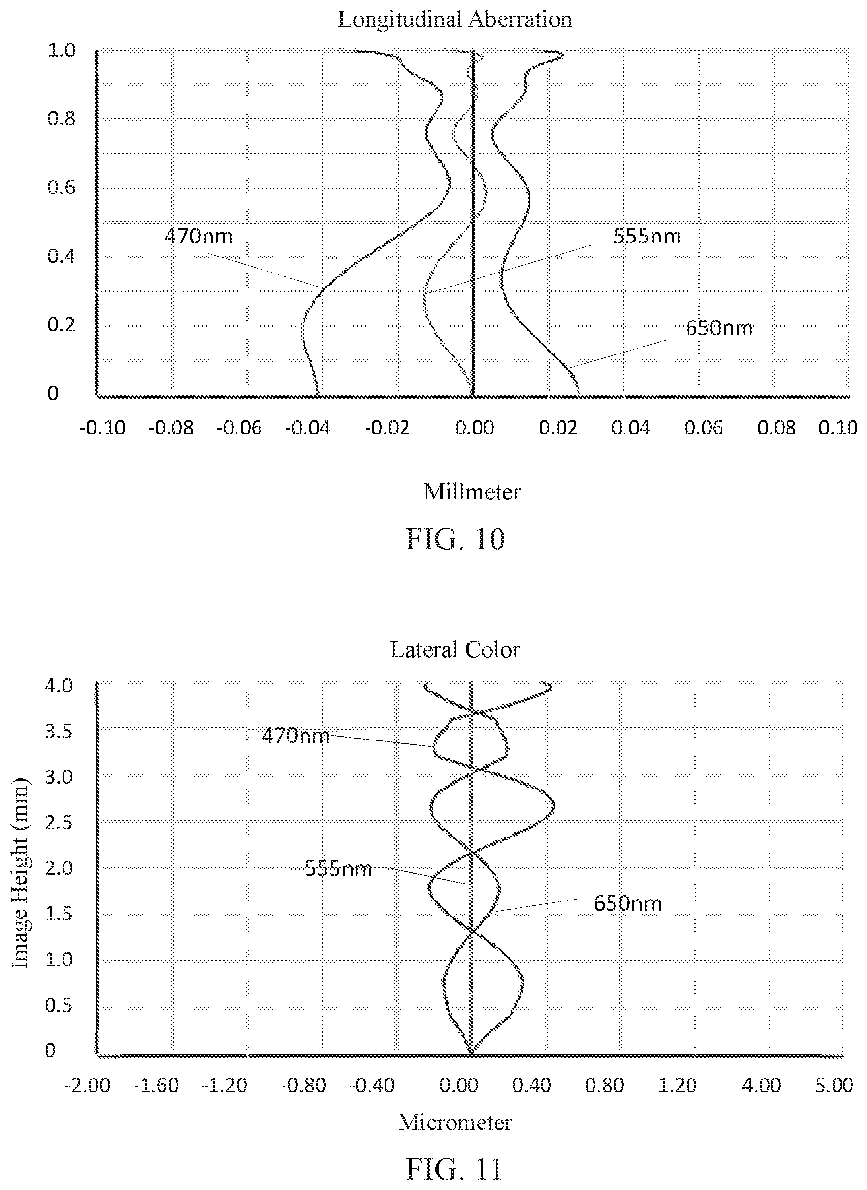
[0132] FIG. 10 and FIG. 11 illustrate a longitudinal aberration and a lateral color of light with wavelengths of 470 nm, 510 nm, 555 nm, 610 nm and 650 nm after passing the camera optical lens 30 according to Embodiment 3. FIG. 12 illustrates field curvature and distortion of light with a wavelength of 555 nm after passing the camera optical lens 30 according to Embodiment 3.
[0133] Table 13 in the following lists values corresponding to the respective conditions in this embodiment in order to satisfy the above conditions. The camera optical lens according to this embodiment satisfies the above conditions.
[0134] In this embodiment, the entrance pupil diameter of the camera optical lens is 3.384 mm. The image height of 1.0H is 4.00 mm. The FOV (field of view) is 78.10.degree.. Thus, the camera optical lens has a wide-angle and is ultra-thin. Its on-axis and off-axis chromatic aberrations are fully corrected, thereby achieving excellent optical characteristics.
TABLE-US-00013 TABLE 13 Parameters Embodiment Embodiment Embodiment and conditions 1 2 3 f 4.838 4.835 4.839 f1 9.706 7.325 7.311 f2 25.531 191.289 395.787 f3 -4153.28 -20.728 -72.154 f4 -2078.88 349.586 36.443 f5 -12.219 -10.218 -17.262 f6 2.986 2.745 3.437 f7 -3.375 -4.204 -3.336 f12 7.104 6.898 6.845 FNO 1.43 1.43 1.43 f1/f 2.01 1.51 1.51 f3/f4 2.00 -0.06 -1.98 n5 1.71 1.70 2.10 d9/TTL 0.05 0.06 0.01 (R13 + R14)/(R13 - R14) 0.11 -0.60 0.18
[0135] It can be appreciated by one having ordinary skill in the art that the description above is only embodiments of the present disclosure. In practice, one having ordinary skill in the art can make various modifications to these embodiments in forms and details without departing from the spirit and scope of the present disclosure.
* * * * *
D00000
D00001
D00002
D00003
D00004
D00005
D00006
D00007
D00008
D00009
P00001
XML
uspto.report is an independent third-party trademark research tool that is not affiliated, endorsed, or sponsored by the United States Patent and Trademark Office (USPTO) or any other governmental organization. The information provided by uspto.report is based on publicly available data at the time of writing and is intended for informational purposes only.
While we strive to provide accurate and up-to-date information, we do not guarantee the accuracy, completeness, reliability, or suitability of the information displayed on this site. The use of this site is at your own risk. Any reliance you place on such information is therefore strictly at your own risk.
All official trademark data, including owner information, should be verified by visiting the official USPTO website at www.uspto.gov. This site is not intended to replace professional legal advice and should not be used as a substitute for consulting with a legal professional who is knowledgeable about trademark law.