Systems And Methods Including Multi-mode Operation Of Optically Pumped Magnetometer(s)
Alford; Jamu ; et al.
U.S. patent application number 16/814926 was filed with the patent office on 2020-07-02 for systems and methods including multi-mode operation of optically pumped magnetometer(s). The applicant listed for this patent is HI LLC. Invention is credited to Jamu Alford, Ricardo Jimenez-Martinez.
| Application Number | 20200209328 16/814926 |
| Document ID | / |
| Family ID | 69641002 |
| Filed Date | 2020-07-02 |


View All Diagrams
| United States Patent Application | 20200209328 |
| Kind Code | A1 |
| Alford; Jamu ; et al. | July 2, 2020 |
SYSTEMS AND METHODS INCLUDING MULTI-MODE OPERATION OF OPTICALLY PUMPED MAGNETOMETER(S)
Abstract
A magnetic field measurement system that includes at least one magnetometer; at least one magnetic field generator; a processor coupled to the at least one magnetometer and the at least one magnetic field generator and configured to: measure an ambient background magnetic field using at least one of the at least one magnetometer in a first mode selected from a scalar mode or a vector mode; generate, in response to the measurement of the ambient background magnetic field, a compensation field using the at least one magnetic field generator; and measure a target magnetic field using at least one of the at least one magnetometer in a spin exchange relaxation free (SERF) mode which is different from the first mode.
| Inventors: | Alford; Jamu; (Simi Valley, CA) ; Jimenez-Martinez; Ricardo; (North Hills, CA) | ||||||||||
| Applicant: |
|
||||||||||
|---|---|---|---|---|---|---|---|---|---|---|---|
| Family ID: | 69641002 | ||||||||||
| Appl. No.: | 16/814926 | ||||||||||
| Filed: | March 10, 2020 |
Related U.S. Patent Documents
| Application Number | Filing Date | Patent Number | ||
|---|---|---|---|---|
| 16213980 | Dec 7, 2018 | 10627460 | ||
| 16814926 | ||||
| 62723933 | Aug 28, 2018 | |||
| Current U.S. Class: | 1/1 |
| Current CPC Class: | G01R 33/0017 20130101; A61B 5/4064 20130101; A61B 5/04008 20130101; G01R 33/26 20130101 |
| International Class: | G01R 33/26 20060101 G01R033/26 |
Claims
1. A magnetic field measurement system, comprising: at least one first magnetometer configured for operation in a first mode selected from a scalar mode or a vector mode; at least one second magnetometer configured for operation in a spin exchange relaxation free (SERF) mode which is different from the first mode; at least one magnetic field generator; and a processor coupled to the at least one first magnetometer, the at least one second magnetometer, and the at least one magnetic field generator and configured to: measure an ambient background magnetic field using at least one of the at least one first magnetometer; and generate a compensation field by the at least one magnetic field generator based on the measurement from the at least one first magnetometer.
2. The magnetic field measurement system of claim 1, wherein each of the at least one first magnetometer and each of the at least one second magnetometer comprises a vapor cell and at least one of the at least one first magnetometer and at least one of the at least one second magnetometers share the same vapor cell.
3. The magnetic field measurement system of claim 1, wherein the processor is further configured to: measure the ambient background magnetic field, reduced by compensation field, using at least one of the at least one second magnetometer; and update, in response to the measurement of the ambient background magnetic field reduced by compensation field, the compensation field using the at least one magnetic field generator.
4. The magnetic field measurement system of claim 1, wherein measuring the ambient background magnetic field comprises, for each of two or three orthogonal axes: applying a first magnetic field along the axis; sweeping a frequency of the first magnetic field; measuring responses by the at least one of the at least one first magnetometer in the first mode during the sweeping; and determining a vector component of the ambient background magnetic field along the axis by observing a maximum or minimum in the responses or fitting the responses to a Lorentzian function.
5. The magnetic field measurement system of claim 1, wherein measuring the ambient background magnetic field comprises: applying a first magnetic field along a first axis; sweeping a frequency of the first magnetic field; measuring responses by the at least one of the at least one first magnetometer in the first mode during the sweeping; and determining a magnitude of the ambient background magnetic field along the axis by observing a maximum or minimum in the responses or fitting the responses to a Lorentzian function.
6. The magnetic field measurement system of claim 5, wherein measuring the ambient background magnetic field further comprises, for each of two or three orthogonal axes: applying a first magnetic field along the axis; modulating the first magnetic field; measuring responses by the at least one of the at least one first or second magnetometer in a vector mode during the modulation; and determining a vector component of the ambient background magnetic field along the axis by observing the responses to the modulated first magnetic field.
7. The magnetic field measurement system of claim 1, further comprising at least one local oscillator coupled to at least one of the at least one magnetic field generator; and at least one lock-in amplifier, each of the at least one lock-in amplifier coupled to a one of the at least one local oscillator and at least one of the at least one first magnetometer.
8. A non-transitory processor readable storage media that includes instructions for operating a magnetic field measurement system comprising at least one magnetometer and at least one magnetic field generator, wherein execution of the instructions by one or more processors cause the one or more processors to perform actions, comprising: i) measuring an ambient background magnetic field using at least one of the at least one magnetometer operating in a first mode selected from a scalar mode or a vector mode; ii) generating, in response to the measurement of the ambient background magnetic field, a compensation field using the at least one magnetic field generator; iii) measuring a target magnetic field using at least one of the at least one magnetometer operating in a spin exchange relaxation free (SERF) mode which is different from the first mode; and iv) determining when the at least one of the at least one magnetometer is not operating in SERF mode and automatically performing steps i) and ii) again.
9. The non-transitory processor readable storage media of claim 8, wherein measuring the ambient background magnetic field using the at least one of the at least one magnetometer operating in a first mode and measuring the target magnetic field using at least one of the at least one magnetometer operating in the spin exchange relaxation free (SERF) mode comprise measuring the ambient background magnetic field and measuring the target magnetic field using the same magnetometer.
10. The non-transitory processor readable storage media of claim 8, wherein the actions further comprise: measuring the ambient background magnetic field, reduced by compensation field, using at least one of the at least one magnetometer in the SERF mode; and updating, in response to the measurement of the ambient background magnetic field reduced by compensation field, the compensation field using the at least one magnetic field generator.
11. The non-transitory processor readable storage media of claim 8, wherein measuring the ambient background magnetic field comprises, for each of two or three orthogonal axes: applying a first magnetic field along the axis; sweeping a frequency of the first magnetic field; measuring responses by the at least one of the at least one magnetometer in the first mode during the sweeping; and determining a vector component of the ambient background magnetic field along the axis by observing a maximum or minimum in the responses or fitting the responses to a Lorentzian function.
12. The non-transitory processor readable storage media of claim 8, wherein measuring the ambient background magnetic field comprises: applying a first magnetic field along a first axis; sweeping a frequency of the first magnetic field; measuring responses by the at least one of the at least one magnetometer in the first mode during the sweeping; and determining a magnitude of the ambient background magnetic field along the axis by observing a maximum or minimum in the responses or fitting the responses to a Lorentzian function.
13. The non-transitory processor readable storage media of claim 12, wherein measuring the ambient background magnetic field further comprises, for each of two or three orthogonal axes: applying a first magnetic field along the axis; modulating the first magnetic field; measuring responses by the at least one of the at least one magnetometer in a vector mode during the modulation; and determining a vector component of the ambient background magnetic field along the axis by observing the responses to the modulated first magnetic field.
14. A method of operating the magnetic field measurement of claim 1, the method comprising: measuring an ambient background magnetic field using at least one of the at least one first magnetometer; and generating a compensation field by the at least one magnetic field generator based on the measurement from the at least one first magnetometer.
15. The method of claim 14, further comprising measuring the ambient background magnetic field, reduced by compensation field, using at least one of the at least one second magnetometer; and updating, in response to the measurement of the ambient background magnetic field reduced by compensation field, the compensation field using the at least one magnetic field generator.
16. The method of claim 14, wherein measuring the ambient background magnetic field comprises, for each of two or three orthogonal axes: applying a first magnetic field along the axis; sweeping a frequency of the first magnetic field; measuring responses by the at least one of the at least one first magnetometer in the first mode during the sweeping; and determining a vector component of the ambient background magnetic field along the axis by observing a maximum or minimum in the responses or fitting the responses to a Lorentzian function.
17. The method of claim 14, wherein measuring the ambient background magnetic field comprises: applying a first magnetic field along a first axis; sweeping a frequency of the first magnetic field; measuring responses by the at least one of the at least one first magnetometer in the first mode during the sweeping; and determining a magnitude of the ambient background magnetic field along the axis by observing a maximum or minimum in the responses or fitting the responses to a Lorentzian function.
18. The method of claim 17, wherein measuring the ambient background magnetic field further comprises, for each of two or three orthogonal axes: applying a first magnetic field along the axis; modulating the first magnetic field; measuring responses by the at least one of the at least one first or second magnetometer in a vector mode during the modulation; and determining a vector component of the ambient background magnetic field along the axis by observing the responses to the modulated first magnetic field.
19. The method of claim 14, wherein each of the at least one first magnetometer and each of the at least one second magnetometer comprises a vapor cell and at least one of the at least one first magnetometer and at least one of the at least one second magnetometers share the same vapor cell.
20. The method of claim 14, wherein the magnetic field measurement system further comprises at least one local oscillator coupled to at least one of the at least one magnetic field generator; and at least one lock-in amplifier, each of the at least one lock-in amplifier coupled to a one of the at least one local oscillator and at least one of the at least one first magnetometer.
Description
CROSS-REFERENCE TO RELATED APPLICATIONS
[0001] This application is a divisional of U.S. patent application Ser. No. 16/213,980, filed Dec. 7, 2018, which claims the benefit of U.S. Provisional Patent Application Ser. No. 62/723,933, filed Aug. 28, 2018, both of which are incorporated herein by reference in their entirety.
FIELD
[0002] The present disclosure is directed to the area of magnetic field measurement systems using one or more optically pumped magnetometers. The present disclosure is also directed to magnetic field measurement systems and methods that include operation in scalar/vector and spin exchange relaxation free (SERF) modes using one or more magnetometers.
BACKGROUND
[0003] In the nervous system, neurons propagate signals via action potentials. These are brief electric currents which flow down the length of a neuron causing chemical transmitters to be released at a synapse. The time-varying electrical current within the neuron generates a magnetic field, which propagates through the human body and can be measured using either a Superconductive Quantum Interference Device (SQUID) or an Optically Pumped Magnetometer (OPM). In this disclosure the OPM is primarily considered because the SQUID requires cryogenic cooling, which may make it prohibitively costly for users and too large to be wearable by a user. In addition to OPMs and SQUIDs, other magnetic sensing technologies for detection of magnetic fields from the brain include and magnetoresistance.
[0004] Optical magnetometry can include the use of optical methods to measure a magnetic field with very high accuracy--on the order of 1.times.10.sup.-15 Tesla. Of particular interest for their high-sensitivity, an optically pumped magnetometer (OPM) can be used in optical magnetometry to measure weak magnetic fields. In at least some embodiments, the OPM has an alkali vapor gas cell that contains alkali metal atoms in a combination of gas, liquid, or solid states (depending on temperature). The gas cell may contain a quenching gas, buffer gas, or specialized antirelaxation coatings or any combination thereof. The size of the gas cells can vary from a fraction of a millimeter up to several centimeters.
BRIEF SUMMARY
[0005] One embodiment is a magnetic field measurement system that includes at least one magnetometer; at least one magnetic field generator; a processor coupled to the at least one magnetometer and the at least one magnetic field generator and configured to: i) measure an ambient background magnetic field using at least one of the at least one magnetometer in a first mode selected from a scalar mode or a vector mode; ii) generate, in response to the measurement of the ambient background magnetic field, a compensation field using the at least one magnetic field generator; iii) measure a target magnetic field using at least one of the at least one magnetometer in a spin exchange relaxation free (SERF) mode which is different from the first mode and iv) determine when the at least one of the at least one magnetometer is not operating in SERF mode and automatically perform steps i) and ii) again. For example, the first mode can be a scalar mode or a non-SERF vector mode.
[0006] In at least some embodiments, the at least one magnetometer includes a first magnetometer configured to operate in both the first mode and the SERF mode and the processor is configured to operate the first magnetometer in both the first mode and the SERF mode. In at least some embodiments, the at least one magnetometer includes a first magnetometer configured to operate in the first mode and a second magnetometer configured to operate in the SERF mode. In at least some embodiments, each of the at least one magnetometer includes a vapor cell and the first and second magnetometers share the same vapor cell.
[0007] In at least some embodiments, the processor is further configured to: measure the ambient background magnetic field, reduced by compensation field, using at least one of the at least one magnetometer in the SERF mode; and update, in response to the measurement of the ambient background magnetic field reduced by compensation field, the compensation field using the at least one magnetic field generator. In at least some embodiments, measuring the ambient background magnetic field includes, for each of two or three orthogonal axes: applying a first magnetic field along the axis; sweeping a frequency of the first magnetic field; measuring responses by the at least one of the at least one magnetometer in the first mode during the sweeping; and determining a vector component of the ambient background magnetic field along the axis by observing a maximum or minimum in the responses or fitting the responses to a Lorentzian function.
[0008] In at least some embodiments, measuring the ambient background magnetic field includes applying a first magnetic field along a first axis; sweeping a frequency of the first magnetic field; measuring responses by the at least one of the at least one magnetometer in the first mode during the sweeping; and determining a magnitude of the ambient background magnetic field along the axis by observing a maximum or minimum in the responses or fitting the responses to a Lorentzian function. In at least some embodiments, measuring the ambient background magnetic field further includes, for each of two or three orthogonal axes: applying a first magnetic field along the axis; modulating the first magnetic field; measuring responses by the at least one of the at least one magnetometer in a vector mode during the modulation; and determining a vector component of the ambient background magnetic field along the axis by observing the responses to the modulated first magnetic field.
[0009] In at least some embodiments, the magnetic field measurement system further includes at least one local oscillator coupled to the at least one magnetometer; and at least one lock-in amplifier, each of the at least one lock-in amplifier coupled to a one of the at least one local oscillator and at least one of the at least one magnetometer.
[0010] Another embodiment is a magnetic field measurement system that includes at least one first magnetometer configured for operation in a first mode selected from a scalar mode or a vector mode; at least one second magnetometer configured for operation in a spin exchange relaxation free (SERF) mode which is different from the first mode; at least one magnetic field generator; and a processor coupled to the at least one first magnetometer, the at least one second magnetometer, and the at least one magnetic field generator and configured to: measure an ambient background magnetic field using at least one of the at least one first magnetometer; and generate of a compensation field by the at least one magnetic field generator based on the measurement from the at least one first magnetometer. For example, the first mode can be a scalar mode or a non-SERF vector mode.
[0011] In at least some embodiments, each of the at least one first magnetometer and each of the at least one second magnetometer includes a vapor cell and at least one of the at least one first magnetometer and at least one of the at least one second magnetometers share the same vapor cell.
[0012] In at least some embodiments, the processor is further configured to: measure the ambient background magnetic field, reduced by compensation field, using at least one of the at least one second magnetometer; and update, in response to the measurement of the ambient background magnetic field reduced by compensation field, the compensation field using the at least one magnetic field generator. In at least some embodiments, measuring the ambient background magnetic field includes, for each of two or three orthogonal axes: applying a first magnetic field along the axis; sweeping a frequency of the first magnetic field; measuring responses by the at least one of the at least one first magnetometer in the first mode during the sweeping; and determining a vector component of the ambient background magnetic field along the axis by observing a maximum or minimum in the responses or fitting the responses to a Lorentzian function.
[0013] In at least some embodiments, measuring the ambient background magnetic field includes: applying a first magnetic field along a first axis; sweeping a frequency of the first magnetic field; measuring responses by the at least one of the at least one first magnetometer in the first mode during the sweeping; and determining a magnitude of the ambient background magnetic field along the axis by observing a maximum or minimum in the responses or fitting the responses to a Lorentzian function. In at least some embodiments, measuring the ambient background magnetic field further includes, for each of two or three orthogonal axes: applying a first magnetic field along the axis; modulating the first magnetic field; measuring responses by the at least one of the at least one first or second magnetometer in a vector mode during the modulation; and determining a vector component of the ambient background magnetic field along the axis by observing the responses to the modulated first magnetic field.
[0014] In at least some embodiments, the magnetic field measurement system further includes at least one local oscillator coupled to at least one of the at least one first magnetometer; and at least one lock-in amplifier, each of the at least one lock-in amplifier coupled to a one of the at least one local oscillator and at least one of the at least one first magnetometer.
[0015] A further embodiment is a non-transitory processor readable storage media that includes instructions for operating a magnetic field measurement system including at least one magnetometer and at least one magnetic field generator, wherein execution of the instructions by one or more processors cause the one or more processors to perform actions, including: i) measuring an ambient background magnetic field using at least one of the at least one magnetometer operating in a first mode selected from a scalar mode or a vector mode; ii) generating, in response to the measurement of the ambient background magnetic field, a compensation field using the at least one magnetic field generator; iii) measuring a target magnetic field using at least one of the at least one magnetometer operating in a spin exchange relaxation free (SERF) mode which is different from the first mode and iv) determining when the at least one of the at least one magnetometer is not operating in SERF mode and automatically performing steps i) and ii) again. For example, the first mode can be a scalar mode or a non-SERF vector mode.
[0016] In at least some embodiments, measuring the ambient background magnetic field using the at least one of the at least one magnetometer operating in a first mode and measuring the target magnetic field using at least one of the at least one magnetometer operating in the spin exchange relaxation free (SERF) mode include measuring the ambient background magnetic field and measuring the target magnetic field using the same magnetometer. In at least some embodiments, the actions further include: measuring the ambient background magnetic field, reduced by compensation field, using at least one of the at least one magnetometer in the SERF mode; and updating, in response to the measurement of the ambient background magnetic field reduced by compensation field, the compensation field using the at least one magnetic field generator.
[0017] In at least some embodiments, measuring the ambient background magnetic field includes, for each of two or three orthogonal axes: applying a first magnetic field along the axis; sweeping a frequency of the first magnetic field; measuring responses by the at least one of the at least one magnetometer in the first mode during the sweeping; and determining a vector component of the ambient background magnetic field along the axis by observing a maximum or minimum in the responses or fitting the responses to a Lorentzian function.
[0018] In at least some embodiments, measuring the ambient background magnetic field includes: applying a first magnetic field along a first axis; sweeping a frequency of the first magnetic field; measuring responses by the at least one of the at least one magnetometer in the first mode during the sweeping; and determining a magnitude of the ambient background magnetic field along the axis by observing a maximum or minimum in the responses or fitting the responses to a Lorentzian function. In at least some embodiments, measuring the ambient background magnetic field further includes, for each of two or three orthogonal axes: applying a first magnetic field along the axis; modulating the first magnetic field; measuring responses by the at least one of the at least one magnetometer in a vector mode during the modulation; and determining a vector component of the ambient background magnetic field along the axis by observing the responses to the modulated first magnetic field.
[0019] Yet another embodiment is a method of operating a magnetic field measurement system that includes at least one magnetometer and at least one magnetic field generator. The method includes i) measuring an ambient background magnetic field using at least one of the at least one magnetometer operating in a first mode selected from a scalar mode or a vector mode; ii) generating, in response to the measurement of the ambient background magnetic field, a compensation field using the at least one magnetic field generator; iii) measuring a target magnetic field using at least one of the at least one magnetometer operating in a spin exchange relaxation free (SERF) mode which is different from the first mode; and iv) determining when the at least one of the at least one magnetometer is not operating in SERF mode and performing steps i) and ii) again. For example, the first mode can be a scalar mode or a non-SERF vector mode.
[0020] In at least some embodiments, measuring the ambient background magnetic field using the at least one of the at least one magnetometer operating in the first mode and measuring the target magnetic field using at least one of the at least one magnetometer operating in the spin exchange relaxation free (SERF) mode include measuring the ambient background magnetic field and measuring the target magnetic field using the same magnetometer.
[0021] In at least some embodiments, measuring the ambient background magnetic field using the at least one of the at least one magnetometer operating in a first mode includes measuring the ambient background magnetic field using a first magnetometer of the at least one magnetometer, the first magnetometer operating in the first mode; and measuring the target magnetic field using at least one of the at least one magnetometer operating in the spin exchange relaxation free (SERF) mode include measuring the target magnetic field using a second magnetometer of the at least one magnetometer, the first magnetometer operating in the SERF mode. In at least some embodiments, each of the at least one magnetometer includes a vapor cell and the first and second magnetometers share the same vapor cell.
[0022] In at least some embodiments, the method further includes measuring the ambient background magnetic field, reduced by compensation field, using at least one of the at least one magnetometer in the SERF mode; and updating, in response to the measurement of the ambient background magnetic field reduced by compensation field, the compensation field using the at least one magnetic field generator. In at least some embodiments, measuring the ambient background magnetic field includes, for each of two or three orthogonal axes: applying a first magnetic field along the axis; sweeping a frequency of the first magnetic field; measuring responses by the at least one of the at least one magnetometer in the first mode during the sweeping; and determining a vector component of the ambient background magnetic field along the axis by observing a maximum or minimum in the responses or fitting the responses to a Lorentzian function.
[0023] In at least some embodiments, measuring the ambient background magnetic field includes: applying a first magnetic field along a first axis; sweeping a frequency of the first magnetic field; measuring responses by the at least one of the at least one magnetometer in the first mode during the sweeping; and determining a magnitude of the ambient background magnetic field along the axis by observing a maximum or minimum in the responses or fitting the responses to a Lorentzian function. In at least some embodiments, measuring the ambient background magnetic field further includes, for each of two or three orthogonal axes: applying a first magnetic field along the axis; modulating the first magnetic field; measuring responses by the at least one of the at least one magnetometer in a vector mode during the modulation; and determining a vector component of the ambient background magnetic field along the axis by observing the responses to the modulated first magnetic field.
BRIEF DESCRIPTION OF THE DRAWINGS
[0024] Non-limiting and non-exhaustive embodiments of the present invention are described with reference to the following drawings. In the drawings, like reference numerals refer to like parts throughout the various figures unless otherwise specified.
[0025] For a better understanding of the present invention, reference will be made to the following Detailed Description, which is to be read in association with the accompanying drawings, wherein:
[0026] FIG. 1A is a schematic block diagram of one embodiment of a magnetic field measurement system, according to the invention;
[0027] FIG. 1B is a schematic block diagram of one embodiment of a magnetometer, according to the invention;
[0028] FIG. 1C is a schematic block diagram of one embodiment of optical element of a magnetometer, according to the invention;
[0029] FIG. 2 shows a magnetic spectrum with lines indicating dynamic ranges of magnetometers operating in different modes;
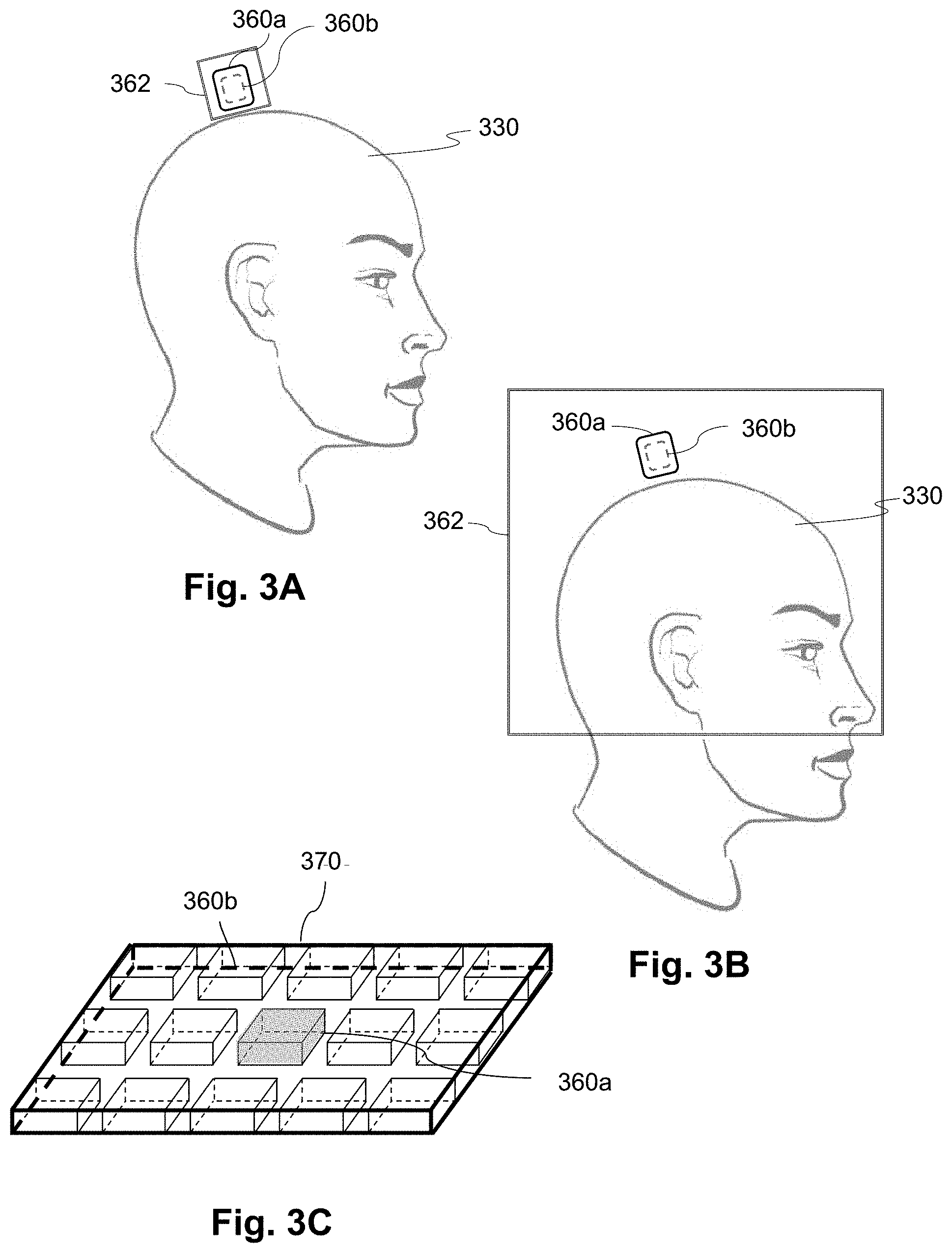
[0030] FIG. 3A is a schematic view of one embodiment of a dual arrangement of a SERF mode magnetometer and a scalar mode magnetometer, according to the invention;
[0031] FIG. 3B is a schematic view of another embodiment of a dual arrangement of a SERF mode magnetometer and a scalar mode magnetometer, according to the invention;
[0032] FIG. 3C is a schematic view of a vapor cell of yet another embodiment of a dual arrangement of a SERF mode magnetometer and a scalar mode magnetometer, according to the invention
[0033] FIG. 4 is a flowchart of one embodiment of method of operating a magnetic field measurement system, according to the invention;
[0034] FIG. 5 is a flowchart of another embodiment of method of operating a magnetic field measurement system, according to the invention;
[0035] FIG. 6 is a schematic view of yet another embodiment of a dual arrangement of a SERF mode magnetometer and a scalar mode magnetometer along with graphs showing a resulting measured magnetic field with sweeping of applied magnetic fields along the respective axes, according to the invention;
[0036] FIG. 7A is a schematic view of one embodiment of an arrangement of a magnetometer and an auxiliary sensor, according to the invention;
[0037] FIG. 7B is a schematic view of another embodiment of an arrangement of a magnetometer and an auxiliary sensor, according to the invention;
[0038] FIG. 8 is a flowchart of one embodiment of method of determining a compensation field, according to the invention;
[0039] FIG. 9 is a schematic view of one embodiment of an arrangement of a magnetometer, magnetic field generators, a local oscillator, and a lock-in amplifier, according to the invention;
[0040] FIG. 10 is a flowchart of another embodiment of method of determining a compensation field, according to the invention;
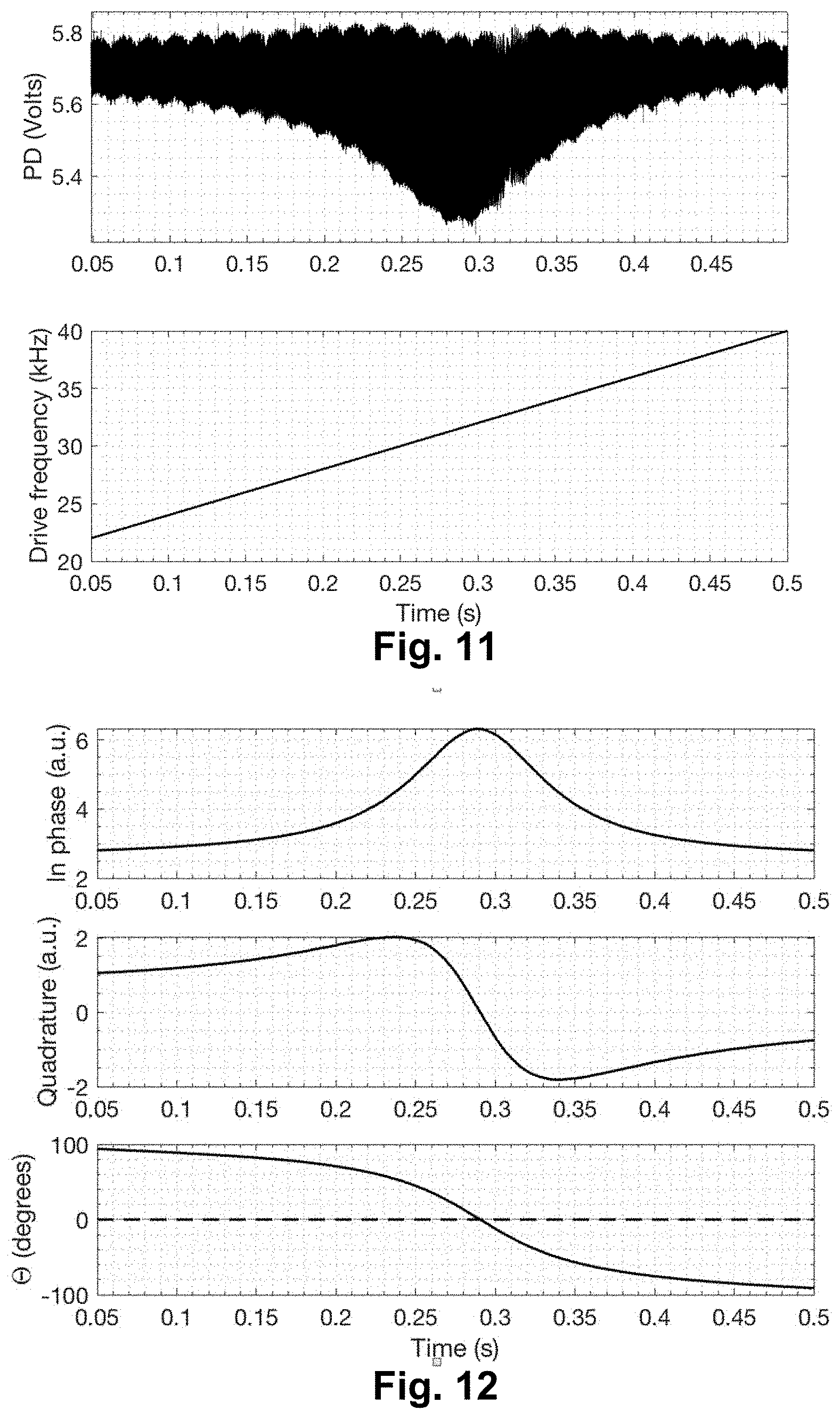
[0041] FIG. 11 illustrates a top graph of measured detector voltage versus time and a bottom graph of drive frequency versus time, according to the invention;
[0042] FIG. 12 illustrates graphs of in-phase ("U"), quadrature ("V"), and phase angle (".theta.") outputs of a lock-in amplifier during sweeping of a frequency of an applied magnetic field, according to the invention; and
[0043] FIG. 13 is a schematic view of one embodiment of an arrangement of a magnetometer, magnetic field generators, three local oscillators, and three lock-in amplifiers, according to the invention.
DETAILED DESCRIPTION
[0044] The present disclosure is directed to the area of magnetic field measurement systems using one or more optically pumped magnetometers. The present disclosure is also directed to magnetic field measurement systems and methods that include operation in scalar/vector and spin exchange relaxation free (SERF) modes using one or more magnetometers.
[0045] Herein the terms "ambient background magnetic field" and "background magnetic field" are interchangeable and used to identify the magnetic field or fields associated with sources other than the magnetic field measurement system and the biological source(s) (for example, neural signals from a user's brain) or other source(s) of interest. The terms can include, for example, the Earth's magnetic field, as well as magnetic fields from magnets, electromagnets, electrical devices, and other signal or field generators in the environment, except for the magnetic field generator(s) that are part of the magnetic field measurement system.
[0046] The terms "gas cell", "vapor cell", and "vapor gas cell" are used interchangeably herein. Below, a gas cell containing alkali metal vapor is described, but it will be recognized that other gas cells can contain different gases or vapors for operation.
[0047] An optically pumped magnetometer (OPM) is a basic component used in optical magnetometry to measure magnetic fields. While there are many types of OPMs, in general magnetometers operate in two modalities: vector mode and scalar mode. In vector mode, the OPM can measure one, two, or all three vector components of the magnetic field; while in scalar mode the OPM can measure the total magnitude of the magnetic field.
[0048] Vector mode magnetometers measure a specific component of the magnetic field, such as the radial and tangential components of magnetic fields with respect the scalp of the human head. Vector mode OPMs often operate at zero-fields and may utilize a spin exchange relaxation free (SERF) mode to reach femto-Tesla sensitivities. A SERF mode OPM is one example of a vector mode OPM, but other vector mode OPMs can be used at higher magnetic fields. These SERF mode magnetometers can have high sensitivity but in general cannot function in the presence of magnetic fields higher than the linewidth of the magnetic resonance of the atoms of about 10 nT, which is much smaller than the magnetic field strength generated by the Earth. As a result, conventional SERF mode magnetometers often operate inside magnetically shielded rooms that isolate the sensor from ambient magnetic fields including Earth's.
[0049] Magnetometers operating in the scalar mode can measure the total magnitude of the magnetic field. (Magnetometers in the vector mode can also be used for magnitude measurements.) Scalar mode OPMs often have lower sensitivity than SERF mode OPMs. However, scalar mode OPMs can operate in unshielded environments up to and including the Earth field, which is about 50 .mu.T. Furthermore, as the magnetic readings from scalar mode OPMs do not suffer from long-term drifts and bias they are frequently used to calibrate other magnetic sensors.
[0050] In optically pumped magnetometers (OPMs), which are based on the precession of atomic spins, another classification is based on the strength of the effective magnetic field experienced by the atoms in the gas cell, where two regimes are identified: zero-field mode and finite-field mode. Finite-field OPMs operate in a regime where the magnitude of the field experienced by the atoms is much larger than the width of their magnetic resonance. Examples of finite-field OPMs include both scalar and vector mode magnetometers in driven, relaxation, and free-induction decay modalities.
[0051] Zero-field OPMs operate in an effective magnetic field whose strength is smaller, or comparable, to the linewidth of the magnetic resonance of the atoms. It will be understood that a zero-field OPM need not operate in strictly zero magnetic field, but rather in a relatively low magnetic field as described in the preceding sentence. Examples of zero-field magnetometers include OPMs operating in SERF mode in either DC or modulated schemes. Zero-field magnetometers typically measure one or two vector components of the field and are among the most sensitive magnetometers to date. However, as their operation requires a low magnetic field environment, they are usually deployed inside expensive, bulky, and sophisticated magnetically shielded rooms.
[0052] In any OPM mode (SERF, vector, or scalar) magnetic noise should be considered. For instance, in one specific application of OPMs that involves measuring magnetic signals from the brain (i.e. magnetoencephalography or MEG), magnetic noise arises from oscillations of the magnetic field which have the same frequencies as neural signals and can overwhelm the magnetic signals of the brain. If these signals originate far from the region of interest (e.g., the human brain) then they can be suppressed by sampling and then subtracting the background field measured by a combination of two sensors. This technique is called gradiometry. First order gradiometer uses two sensors, second order three sensors, and so on. The higher the order the better background is suppressed but results in a more complicated system with many sensors that just measure background signal and don't contribute to the measurement of brain signal.
[0053] Conventional SERF mode systems have often used vapor cell magnetometers in combination with fluxgate or magnetoresistive magnetometers as a way to reach the SERF regime. Such implementations may use readings from the auxiliary sensor (for example, a fluxgate or magnetoresistive device) as error signals that are passed to magnetic coils, on a continuous or periodic or aperiodic basis, to modify or null the ambient background magnetic field at the position of the SERF mode magnetometer. Objectives of this active-shielding technique can include any of the following: i) suppression of the static and slowly varying components of the ambient background magnetic field so that the SERF mode magnetometer can operate within its dynamic range; ii) mitigation of spurious fast-varying fields that, while not bringing the SERF mode magnetometer outside its dynamic range, can be confounded with the target signal; and iii) active suppression of 60 Hz or 50 Hz power line noise that radiates from all alternating current power lines. The difference between 60 Hz and 50 Hz depends on the region of the world where this device is used. North America is 60 Hz while Europe and parts of Asia use 50 Hz. There can be challenges that may limit the performance and versatility of these SERF mode systems, such as, for example, poor common-mode background field rejection ratio due to the use of devices placed far apart from each other (for example, a few centimeters apart) such as in the use of a bulky SERF mode magnetometer and a bulky auxiliary sensor; and the limitation of the SERF mode magnetometer by intrinsic performance of the auxiliary sensor including, for example, (a) intrinsic noise of the auxiliary sensor (which can range, for example, from 1 pT/sqrt(Hz) for fluxgates to hundreds of pT/sqrt(Hz) for magnetoresistance devices, and is at least 1 to 3 orders of magnitude higher than what is required for MEG detection) which is translated to magnetic noise by a feedback loop or (b) the intrinsic offset of the auxiliary sensor (which may be of the order of 10 nT for both fluxgates and magnetoresistance devices and can be outside of the dynamic range of SERF mode magnetometers) which is translated to magnetic offset by a feedback loop.
[0054] In contrast to these conventional systems, systems and methods are described herein that combine SERF mode operation of an optically pumped magnetometer (OPM) with scalar or non-SERF vector mode magnetic field sensing using the same or a different OPM. This system and methods, in at least some embodiments, can enable, for example, wearable magnetoencephalography (MEG) sensing systems.
[0055] The term "non-SERF vector mode", as utilized to describe methods, systems, and other embodiments of the invention, will refer to a magnetometer operating in any vector mode other than the SERF mode.
[0056] A magnetic field measurement system, as described herein, can include one or more (for example, an array of) optically pumped magnetometers. In at least some embodiments, as described herein, the system can be arranged so that at least one (or even all) of the magnetometers can be operated sequentially in i) the scalar or non-SERF vector mode and ii) the SERF mode. In at least some embodiments, the system can be arranged so that at least one of the magnetometers can be operated in the scalar or non-SERF vector mode and at least one of the magnetometers can be operated in the SERF mode. In at least some of these embodiments, a scalar or non-SERF vector mode magnetometer and a SERF mode magnetometer may utilize the same vapor cell, as described below.
[0057] The magnetic field measurement systems described herein can be used to measure or observe electromagnetic signals generated by one or more sources (for example, biological sources). The system can measure biologically generated magnetic fields and, at least in some embodiments, can measure biologically generated magnetic fields in an unshielded or partially shielded environment. Aspects of a magnetic field measurement system will be exemplified below using magnetic signals from the brain of a user; however, biological signals from other areas of the body, as well as non-biological signals, can be measured using the system. Uses for this technology outside biomedical sensing include, but are not limited to, navigation, mineral exploration, non-destructive testing, detection of underground devices, asteroid mining, and space applications. In at least some embodiments, the system can be a wearable MEG system that can be used outside a magnetically shielded room.
[0058] FIG. 1A is a block diagram of components of one embodiment of a magnetic field measurement system 140. The system 140 can include a computing device 150 or any other similar device that includes a processor 152 and a memory 154, a display 156, an input device 158, one or more magnetometers 160, one or more magnetic field generators 162, and, optionally, one or more sensors 164. The system 140 and its use and operation will be described herein with respect to the measurement of neural signals arising from signal sources in the brain of a user as an example. It will be understood, however, that the system can be adapted and used to measure other neural signals, other biological signals, as well as non-biological signals.
[0059] The computing device 150 can be a computer, tablet, mobile device, field programmable gate array (FPGA), microcontroller, or any other suitable device for processing information. The computing device 150 can be local to the user or can include components that are non-local to the user including one or both of the processor 152 or memory 154 (or portions thereof). For example, in at least some embodiments, the user may operate a terminal that is connected to a non-local computing device. In other embodiments, the memory 154 can be non-local to the user.
[0060] The computing device 150 can utilize any suitable processor 152 including one or more hardware processors that may be local to the user or non-local to the user or other components of the computing device. The processor 152 is configured to execute instructions, as described below.
[0061] Any suitable memory 154 can be used for the computing device 150. The memory 154 illustrates a type of computer-readable media, namely computer-readable storage media. Computer-readable storage media may include, but is not limited to, volatile, nonvolatile, non-transitory, removable, and non-removable media implemented in any method or technology for storage of information, such as computer readable instructions, data structures, program modules, or other data. Examples of computer-readable storage media include RAM, ROM, EEPROM, flash memory, or other memory technology, CD-ROM, digital versatile disks ("DVD") or other optical storage, magnetic cassettes, magnetic tape, magnetic disk storage or other magnetic storage devices, or any other medium which can be used to store the desired information and which can be accessed by a computing device.
[0062] Communication methods provide another type of computer readable media; namely communication media. Communication media typically embodies computer-readable instructions, data structures, program modules, or other data in a modulated data signal such as a carrier wave, data signal, or other transport mechanism and include any information delivery media. The terms "modulated data signal," and "carrier-wave signal" includes a signal that has one or more of its characteristics set or changed in such a manner as to encode information, instructions, data, and the like, in the signal. By way of example, communication media includes wired media such as twisted pair, coaxial cable, fiber optics, wave guides, and other wired media and wireless media such as acoustic, RF, infrared, and other wireless media.
[0063] The display 156 can be any suitable display device, such as a monitor, screen, or the like, and can include a printer. In some embodiments, the display is optional. In some embodiments, the display 156 may be integrated into a single unit with the computing device 150, such as a tablet, smart phone, or smart watch. In at least some embodiments, the display is not local to the user. The input device 158 can be, for example, a keyboard, mouse, touch screen, track ball, joystick, voice recognition system, or any combination thereof, or the like. In at least some embodiments, the input device is not local to the user.
[0064] The magnetic field generator(s) 162 can be, for example, Helmholtz coils, solenoid coils, planar coils, saddle coils, electromagnets, permanent magnets, or any other suitable arrangement for generating a magnetic field. The optional sensor(s) 164 can include, but are not limited to, one or more magnetic field sensors, position sensors, orientation sensors, accelerometers, image recorders, or the like or any combination thereof.
[0065] The one or more magnetometers 160 can be any suitable magnetometer including, but not limited to, any suitable optically pumped magnetometer. In at least some embodiments, at least one of the one or more magnetometers (or all of the magnetometers) of the system is arranged for operation in both i) the scalar or non-SERF vector mode and ii) the SERF mode. Alternatively or additionally, the one or more magnetometers 160 of the system include at least one scalar or non-SERF vector mode magnetometer and at least one SERF mode magnetometer. Examples of dual mode systems are disclosed in U.S. Patent Provisional Patent Application Ser. No. 62/723,933, incorporated herein by reference in its entirety.
[0066] As a further example of an optically pumped magnetometer that can operate in both i) the scalar or non-SERF vector mode and ii) the SERF mode, an alkali metal magnetometer can be operated as a zero-field magnetometer with the ability to operate in SERF mode with suppressed spin-exchange relaxation. At finite magnetic fields, such that the Larmor precession frequency is much higher than the intrinsic spin relaxation, the same magnetometer can be used to measure the magnitude of the magnetic field when the magnetometer is operating in the scalar mode (or the non-SERF vector mode).
[0067] FIG. 1B is a schematic block diagram of one embodiment of a magnetometer 160 which includes an alkali metal gas cell 170 (also referred to as a "cell"); a heating device 176 to heat the cell 170; a light source 172; and a detector 174. The gas cell 170 can include, for example, an alkali metal vapor (for example, rubidium in natural abundance, isotopically enriched rubidium, potassium, or cesium, or any other suitable alkali metal such as lithium, sodium, or francium), quenching gas (for example, nitrogen) and buffer gas (for example, nitrogen, helium, neon, or argon). The light source 172 can include, for example, a laser to optically pump the alkali metal atoms and to probe the gas cell, as well as optics (such as lenses, waveplates, collimators, polarizers, and objects with reflective surfaces) for beam shaping and polarization control and for directing the light from the light source to the cell and detector. The detector 174 can include, for example, an optical detector to measure the optical properties of the transmitted light field amplitude, phase, or polarization, as quantified through optical absorption and dispersion curves, spectrum, or polarization or the like or any combination thereof.
[0068] In a scalar mode magnetometer (e.g., an optically pumped magnetometer operating in the scalar mode), in addition to the above elements, a local oscillator (LO) (see, for example, FIG. 9) is added to drive the spin precession on resonance with the Larmor frequency as set by the given ambient field. The excitation can be introduced in the form of an RF field generated using the magnetic field generator 162 or optically by modulating the intensity, frequency, or polarization of the pumping light beam from the light source 172.
[0069] Examples of suitable light sources include, but are not limited to, a diode laser (such as a vertical-cavity surface-emitting laser (VCSEL), distributed Bragg reflector laser (DBR), or distributed feedback laser (DFB)), light-emitting diode (LED), lamp, or any other suitable light source. Examples of suitable detectors include, but are not limited to, a photodiode, charge coupled device (CCD) array, CMOS array, camera, photodiode array, single photon avalanche diode (SPAD) array, avalanche photodiode (APD) array, or any other suitable optical sensor array that can measure the change in transmitted light at the optical wavelengths of interest.
[0070] Examples of magnetic field measurement systems or methods of making such systems or components for such systems are described in U.S. Provisional Patent Applications Ser. Nos. 62/689,696; 62/699,596; 62/719,471; 62/719,475; 62/719,928; 62/723,933; 62/732,327; 62/732,791; 62/741,777; 62/743,343; 62/745,144; 62/747,924; and 62/752,067, all of which are incorporated herein by reference in their entireties.
[0071] FIG. 1C illustrates one example of am optically pumped magnetometer (OPM) 160 that includes a light source 172, a converging lens 178, a wave retarder 180, a vapor cell 170, and a detector 174. The light source 172 (for example, a distributed feedback laser (DFB), vertical cavity surface-emitting laser (VCSEL), or edge emitting laser diode) radiates light at its intrinsic beam divergence angle. The converging lens 178 can be used to collimate the light into a parallel path. The light is transformed from linearly to circularly polarized via the wave retarder 180 (for example, a quarter wave plate). The light passes through the alkali metal vapor in the gas cell 170 and is rotated or absorbed by the alkali metal vapor before being received by the detector 174.
[0072] FIG. 2 shows the magnetic spectrum from 1 fT to 100 .mu.T in magnetic field strength on a logarithmic scale. The magnitude of magnetic fields generated by the human brain are indicated by range 201 and the magnitude of the background ambient magnetic field, including the Earth's magnetic field, by range 202. The strength of the Earth's magnetic field covers a range as it depends on the position on the Earth as well as the materials of the surrounding environment where the magnetic field is measured. Range 210 indicates the approximate measurement range of a magnetometer operating in the SERF mode (e.g., a SERF magnetometer) and range 211 indicates the approximate measurement range of a magnetometer operating in the scalar mode (e.g., a scalar magnetometer.) Typically, a SERF magnetometer is more sensitive than a scalar magnetometer but many conventional SERF magnetometers typically only operate up to about 20 to 200 nT while the scalar magnetometer starts in the 100 fT range but extends above 10 .mu.T. At very high magnetic fields the scalar magnetometer typically becomes nonlinear due to a nonlinear Zeeman splitting of atomic energy levels.
[0073] FIG. 3A illustrates a dual arrangement with a SERF mode magnetometer 360a and a scalar or non-SERF vector mode magnetometer 360b in combination with a magnetic field generator 362. As an example, this dual arrangement could be placed on the scalp 330 of a user to measure MEG. In at least some embodiments, the magnetometers 360a, 360b are at the same location as the two magnetometers both use the same alkali vapor cell or the two magnetometers are actually the same magnetometer operating sequentially in i) the scalar or non-SERF vector mode and ii) the SERF mode. In other embodiments, the magnetometers 360a, 360b are separate from each other, but are preferably located close together.
[0074] FIG. 3B illustrates a dual arrangement of SERF mode magnetometer 360a and a scalar or non-SERF vector mode magnetometer 360b in combination with a magnetic field generator 362 that is placed around a portion of the user's head 330.
[0075] As described in more detail below, the dual arrangement of a SERF mode magnetometer 360a and a scalar or non-SERF vector mode magnetometer 360b can include, but is not limited to, a) a single magnetometer that alternates operation in i) the SERF mode and ii) the scalar or non-SERF vector mode or b) an arrangement using a single vapor cell with a first portion of the vapor cell operating as a SERF mode magnetometer and a second portion of the vapor cell operation as a scalar or non-SERF vector mode magnetometer. Examples of the later arrangement can be found in U.S. Provisional Patent Applications Ser. Nos. 62/699,596 and 62/732,327, both of which are incorporated herein by reference in their entireties. FIG. 3C also illustrates a vapor cell 370 where a portion of the vapor cell forms a SERF mode magnetometer 360a because the ambient background magnetic field at that portion has been reduced sufficiently that the portion can operate in the SERF mode. Other portions of the vapor cell 370 can operate as a scalar or non-SERF vector mode magnetometer 360b. In other embodiments, the magnetometers 360a, 360b are separate from each other, but are preferably located close together.
[0076] The systems and methods as described herein utilize active shielding by employing the magnetic field generators 362. It will be understood, however, that the systems and methods may also include passive shielding using materials such as mu-metal and ferrite or any other suitable components. Examples of passive shielding are found in U.S. Provisional Patent Applications Ser. Nos. 62/719,928 and 62/752,067, all of which are incorporated herein by reference in their entireties.
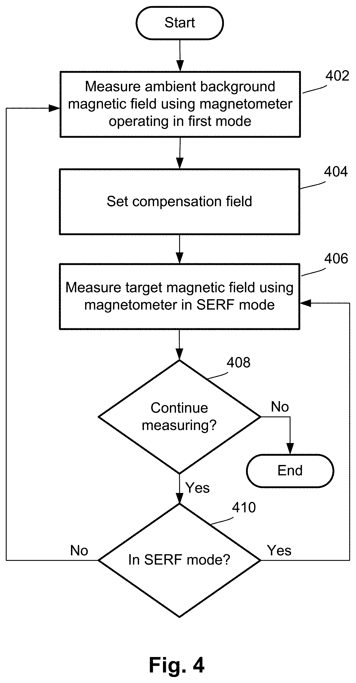
[0077] FIG. 4 illustrates one embodiment of a method of operation or use of a magnetic field measurement system that contains a dual arrangement of a SERF mode magnetometer and a scalar or non-SERF vector mode magnetometer, as well as active shielding using a magnetic field generator or the like, as illustrated in FIGS. 3A and 3B. In step 402, the ambient background magnetic field is measured using the magnetometer operating in a first mode selected from a scalar mode or a non-SERF vector mode. In step 404, this ambient background field is canceled, or reduced substantially (e.g., by at least 80, 90, 95, or 99 percent) by the application of a compensation field (i.e., a local field) using the magnetic field generator. The compensation field may be, for example, equal and opposite to the ambient background magnetic field or at least 80, 90, 95, or 99 percent of the ambient background magnetic field.
[0078] In step 406, the system can measure the vector components of the magnetic field due to neural activity (or any other target magnetic field of interest) using a magnetometer operating in a SERF mode different from the first mode. In step 408, the system or user determines whether to continue measuring. If no, then the system ends operation. If yes, then in step 410 the system determines whether the magnetometer continues to operate in SERF mode. If yes, the system returns to step 406 to make another measurement. If no, such as when the compensation field is no longer sufficient to reduce the ambient background magnetic field to a magnitude that allows the magnetometer to operate in SERF mode (for example, 200 nT, 50 nT, 20 nT, or less), then the system returns to step 402 to measure the ambient background magnetic field and, in step 404, modify or otherwise alter the compensation field.
[0079] As an example of step 410, in at least some embodiments, the system is configured to determine when SERF mode is lost (for example, by comparing transmitted light level as measured by the detector with respect to a threshold value or flatness of response. The SERF mode may be lost when, for example, the ambient background magnetic field undergoes a rapid change in amplitude or direction (or both).
[0080] As an alternative to step 410, the system may automatically switch from the SERF mode to the scalar or non-SERF vector mode periodically (for example, at a specific or selected repetition rate) or aperiodically to perform steps 402 and 404 again. In some embodiments, this switching between modes may occur at least every 0.5, 1, 2, 5, 10, 50, 100, or 500 milliseconds or every 0.5, 1, 2, 5, 10, or 30 seconds or every 1, 2, 5, or 10 minutes.
[0081] FIG. 5 illustrates another embodiment of a method of operation or use of a magnetic field measurement system that contains a dual arrangement of a SERF mode magnetometer and a scalar or non-SERF vector mode magnetometer, as well as active shielding using a magnetic field generator or the like, as illustrated in FIGS. 3A and 3B. In step 502, the ambient background magnetic field is measured using the magnetometer operating in a first mode selected from a scalar mode or a non-SERF vector mode. In step 504, this ambient background field is canceled, or reduced substantially (e.g., by at least 80, 90, 95, or 99 percent) by the application of a compensation field (i.e., a local field) using the magnetic field generator. The compensation field may be, for example, equal and opposite to the ambient background magnetic field or at least 80, 90, 95, or 99 percent of the ambient background magnetic field.
[0082] In step 506, a second measurement of the ambient background magnetic field (as reduced by the compensation field--i.e., the reduced ambient background magnetic field) is performed using a magnetometer operating in a SERF mode different from the first mode. In step 508, in response to this second measurement, the compensation field can be altered or updated to `fine-tune` the cancelation or reduction of the ambient background magnetic field.
[0083] In step 510, the system can measure the vector components of the magnetic field due to neural activity (or any other target magnetic field of interest) using the magnetometer operating in the SERF mode. In step 512, the system or user determines whether to continue measuring. If no, then the system ends operation. If yes, then in step 514 the system determines whether the magnetometer continues to operate in SERF mode. If yes, the system returns to step 510 to make another measurement or, optionally (indicated by the dotted line in FIG. 5), the system returns to step 506 to again measure the reduced ambient background magnetic field with the magnetometer in SERF mode to update the compensation field. If the magnetometer is no longer operating in SERF mode in step 514, such as when the compensation field is no longer sufficient to reduce the ambient background magnetic field to a magnitude that allows the magnetometer to operate in SERF mode (for example, 200 nT, 50 nT, 20 nT, or less), then the system returns to step 502 to measure the ambient background magnetic field and, in step 504, modify or otherwise alter the compensation field.
[0084] One embodiment of a magnetic field measurement system that includes an optically pumped magnetometer 160 (FIG. 1A) that can operate in both i) SERF mode and ii) scalar or non-SERF vector mode at interleaved periods of time using the same vapor cell 170 (FIG. 1B). This approach has the advantage of in situ-magnetometry and compensation or, in other words, the ambient background magnetic field is measured at the same location as the magnetometer that measures the biological or other signal of interest. Alternatively, the magnetic field measurement system includes a vapor cell that can be used for both a SERF mode magnetometer and a scalar or non-SERF vector mode magnetometer as illustrated in FIG. 3C. In other embodiments, the magnetometers are separate from each other, but are preferably located close together.
[0085] In at least some embodiments, these magnetic field measurement systems can operate according to either of the methods illustrated in FIG. 4 or 5, as described above. For example, when the user initially starts up the system (for example, a wearable MEG system) the ambient background magnetic field is measured using a magnetometer in scalar or non-SERF vector mode. Next, the system applies a compensation field using the magnetic field generator (for example, active shielding electromagnets such as Helmholtz coils.) Then the system switches to SERF mode and optionally performs a measurement of the reduced ambient background magnetic field. In at least some embodiments, this high-accuracy measurement allows the system to update the cancelation field to compensate for small changes in the ambient background magnetic field.
[0086] With the system operating in SERF mode, the magnetometer then measures neural activity or other biosignal or signal of interest. In at least some embodiments, the system continues to measure the signal of interest until the compensation field no longer sufficiently reduces the ambient background magnetic field so that the SERF mode is disrupted. Then the system switches back to using scalar or non-SERF vector magnetometry to again measure the ambient background magnetic field and adjust or modify the compensation field so that SERF mode operation is again possible. In at least some embodiments, if the background field drifts slowly the shift will be measured in SERF mode and the compensation coils updated accordingly without leaving SERF mode.
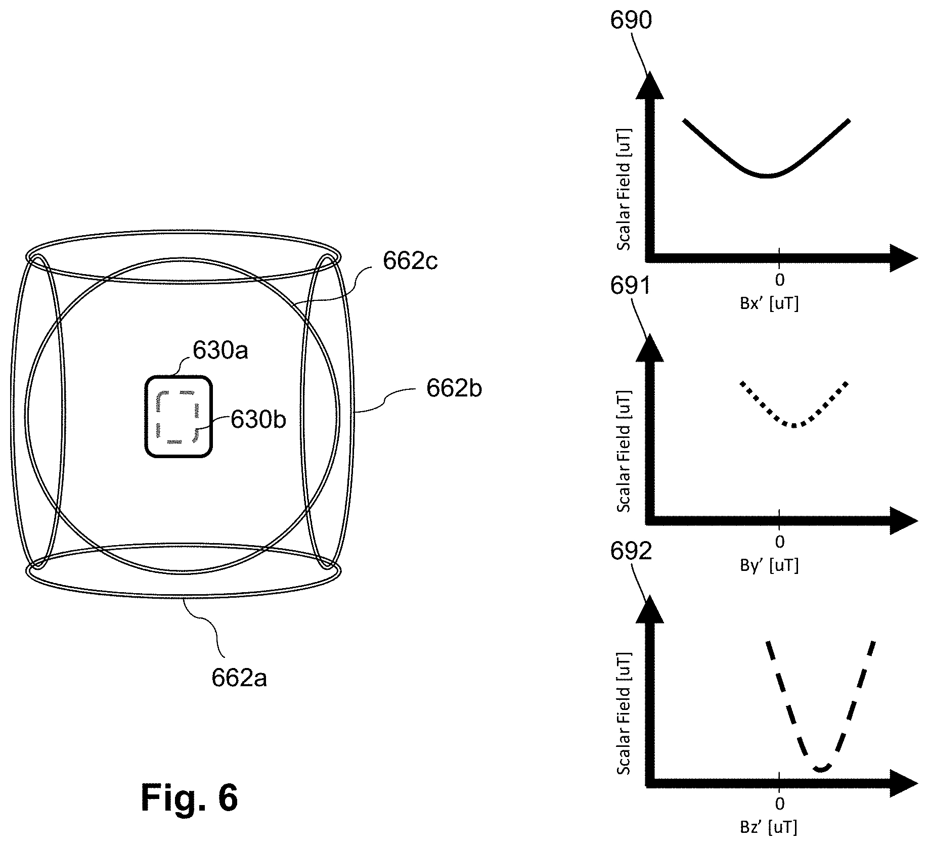
[0087] Referring now to FIG. 6, the system (or any other system described herein) can utilize a dual OPM arrangement 660a, 660b (an arrangement of one or more magnetometers which can operate in i) SERF mode and ii) scalar or non-SERF vector mode, as described above) surrounded by three pairs of compensation coils 662a, 662b, 662c which can generate the three components, Bx', By', Bz', respectively, of the compensation magnetic field to cancel or reduce the ambient background magnetic field (including the Earth's magnetic field). When in the scalar mode, the OPM only measures the magnitude of the ambient background magnetic field but it cannot directly determine the individual three vector components. In other words, the scalar magnetometer measures (Bx.sup.2+By.sup.2+Bz.sup.2).sup.1/2 where Bx, By and Bz are the three Cartesian components of the ambient background magnetic field. To individually measure the three vector components, the magnetic field produced by the three pairs of compensation coils 662a, 662b, 662c can be individually swept to find the minimum of the resulting field, as illustrated in graphs 690, 691, 692, which corresponds to sweeping through the three vector components, Bx', By', Bz', respectively. Each of the graphs 690, 691, 692 illustrate the measured field magnitude versus the swept vector component with the minimum corresponding to the swept vector component approximately equaling the corresponding vector component of the ambient background magnetic field.
[0088] In another embodiment, the scalar mode magnetometer measures the magnitude of the ambient background magnetic field, |B|=(Bx.sup.2+By.sup.2+Bz.sup.2).sup.1/2 where Bx, By and Bz are the three Cartesian components of the ambient background magnetic field. The magnetic field vector generated by the system using the magnetic field generator is given by: B'=xBx'+yBy'+zBz' where x, y and z are Cartesian unit vectors. In a configuration where the laser is oriented along the x-axis of the system, to measure the By component of the background field, the y-axis magnetic field, By', is swept over a range of values, for example, -10 .mu.T to 10 .mu.T and |B| is measured. |B|=(Bx+(By.sup.2+By'.sup.2)+Bz.sup.2).sup.1/2. The output of the detector is a Lorentzian function with a peak at By'=-By. By.sup.C is set at this value. This procedure can be repeated to find Bz. Bx is found by first zeroing By and Bz by applying By.sup.C and Bz.sup.C then sweeping Bx' over the range of interest. When By'=-By the output of the detector reaches a minimum in an inverted Lorentzian. Bx.sup.C is set to the value of Bx' when the minimum occurs. In some instances, an additional oscillating component added to Bx' may be employed to increase the sensitivity of accuracy of the By.sup.C and Bz.sup.C measurements by narrowing the Lorentzian response.
[0089] In other embodiments, the system includes an optically pumped magnetometer that can be operated in SERF mode, an optically pumped magnetometer (the same or different from the first magnetometer) that can be operated in the scalar or non-SERF vector mode, and one or more auxiliary sensors, such as a fluxgate or magnetoresistance device. In at least some embodiments, the one or more auxiliary sensors can be operated concurrently, or at interleaved periods of time with the magnetometer(s). In at least some embodiments, the one or more auxiliary sensors can be operated continually or periodically. In at least some embodiments, the one or more auxiliary sensors can be used to measure the ambient background magnetic field with these measurements can be used to produce the compensation field and the magnetometer operating in the scalar or non-SERF vector mode can be used from time to time to recalibrate the one or more auxiliary sensors. This calibration is useful because the one or more auxiliary sensors are located at a distance from the magnetometer operating in the SERF mode, whereas the magnetometer operating in the scalar or non-SERF vector mode can be the same magnetometer or use the same vapor cell or located near the magnetometer operating in SERF mode. In at least some embodiments, an advantage of the approach is that measurements with the auxiliary sensors may be faster, thus reducing the time between consecutive SERF measurements and measurement bandwidths.
[0090] FIGS. 7A and 7B illustrate two embodiments of arrangements that are similar to those illustrated in FIGS. 3A and 3B, respectively, except that these arrangements include an auxiliary sensor 364 such as a magnetoresistance device or fluxgate sensor, in addition to the magnetometer(s) 360 and magnetic field generator 162 of FIG. 1A.
[0091] There are a variety of methods and techniques for determining the ambient background magnetic field and setting a compensation field. FIG. 8 illustrates one embodiment of such a method which can, at least in some embodiments, be used for steps 402 and 404 in FIG. 4 or steps 502 and 504 in FIG. 5.
[0092] In at least some embodiments, this method uses intensity measurements from an optically pumped magnetometer operating with a single pump/probe laser as the light source and with a single photodiode as the detector (although other light sources and detectors can be used.). When the total magnetic field is aligned with the pump axis (in this case, designated to be the x-axis) the measured optical signal intensity is maximum. Accordingly, if any component of the magnetic field appears along the y or z axes, the measured optical transmitted intensity (TI) will be reduced. It will be understood that the x, y, and z axes described below are interchangeable meaning that the x axis can be replaced by the y or z axes and so on.
[0093] The ambient background magnetic field can be determined by varying the applied fields By' and Bz' until the total intensity is maximum. When this occurs By'.about.-By and Bz'.about.-Bz
[0094] Turning to FIG. 8, in step 802 a large field, Bx.sup.L, is applied by the system where Bx.sup.L is larger than the background Bx to ensure Bx+Bx.sup.L is not zero. For example, if Bx could be any value from -5 .mu.T to 5 .mu.T then adding a Bx.sup.L of 10 uT would results in a non-zero range from 5 .mu.T to 15 .mu.T.
[0095] In step 804, By' is swept along the range of possible By. If the range of expected By were from -5 .mu.T to 5 .mu.T then By' might be swept from -6 .mu.T to 6 .mu.T. In step 806, the transmitted intensity (TI) is monitored during the sweep and the maximum is found when By'.about.-By. By.sup.C is then set to -By, the value that provided the maximum TI. When this is done the total field along the y-axis is zero; By+By.sup.C=0.
[0096] In step 808 Bz' is swept over the expected range of Bz. In step 810, the transmitted intensity (TI) is monitored during the sweep and the maximum is found when Bz'.about.-Bz. Once the maximum TI value is found Bz.sup.C is set to -Bz. When this is done, Bz+Bz.sup.C=0. If completed, there is no remaining magnetic field along the y or z axes.
[0097] In steps 812 to 816, Bx is determined. In step 812, a large background field, By.sup.L, is applied along the y-axis (or equivalently on the z-axis), similar to step 802, and then in step 814 Bx' is swept over the expected range. In step 816, the transmitted intensity (TI) is monitored during the sweep and the maximum is found when Bx'.about.-Bx. Once the maximum TI value is found Bx.sup.C is set to -Bx. When this is done, The total magnetic field along the x-axis is zero: Bx+Bx.sup.C=0.
[0098] Using this procedure in steps 802 to 816, the compensation fields Bx.sup.C, By.sup.C, Bz.sup.C are determined and can be applied using the magnetic field generators with the result that the total remaining magnetic fields from the combination of the background field the and correction fields along each Cartesian axis are all equal zero or are near zero (for example, a reduction of at least 80, 90, 95, or 99 percent in the ambient background magnetic field.)
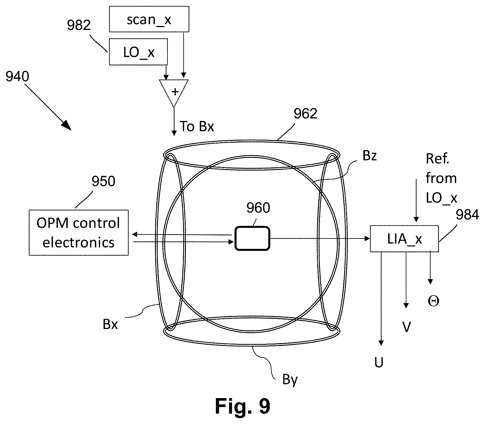
[0099] Other embodiments for determining a compensation field utilize a lock-in amplifier. FIG. 9 illustrates one embodiment of a portion of a magnetic field measurement system 940 with a computing device 950 (designated as the "OPM control electronics"), a magnetometer 960, and a magnetic field generator 962 disposed around the magnetometer. The magnetic field generator 962 includes three pairs of coils (labeled Bx, By, and Bz) and arranged to produce three fields Bx', By', and Bz'. The embodiment illustrated in FIG. 9 has a local oscillator (LO_x) 982 applied to the coils Bx so that the coils Bx can generate an RF field with a frequency .omega..sub.x can be swept as described below. The embodiment illustrated in FIG. 9 also includes a lock-in amplifier (LIA_x) 984 that receives input from the detector of the magnetometer 960 and the local oscillator 982 and can be used to provide in-phase ("U"), quadrature ("V"), and phase angle (".theta.") outputs based on the inputs, as described in more detail below.
[0100] In at least some embodiments, the systems or methods may utilize techniques, such as, but not limited to, least square fitting, filtering, and machine learning, to infer magnetic fields based on sensor outputs and field-generator inputs.
[0101] FIG. 10 illustrates an embodiment of such a method which can, at least in some instances, be used for steps 402 and 404 in FIG. 4 or steps 502 and 504 in FIG. 5. First, a magnetometer operating in scalar mode is used to determine the magnitude |B| of the ambient background magnetic field. FIG. 9, described above, illustrates one arrangement for making such a measurement. The process can be thought of as using a driven oscillator for measuring the resonance frequency .omega..sub.0 of the oscillator, also known as Larmor frequency, that is directly related to the magnitude of the magnetic field B by the gyromagnetic ratio .gamma. of the atomic species used in the OPM according to Equation 2:
.omega..sub.0=.gamma.|B| 2)
[0102] As an example, an OPM is placed inside a passive magnetic shield. The passive shield attenuates the ambient background magnetic field at the position of the OPM by a factor of, for example, 500 to 1000. Alternatively, similar measurements can be performed in an unshielded environment or in a partially shielded environment with shielding factors ranging from 10 to 500. In step 1002, to estimate |B| using the OPM the motion of the spins is driven using an oscillating magnetic field B.sub.mod(t)=B.sub.m cos(.omega..sub.m t) {circumflex over (x)} where .omega..sub.m is generated using a local oscillator (for example, LO_x 982 of FIG. 9). In step 1004, the frequency .omega..sub.m is swept (using, for example, a linear chirp) while the absorption of the transmitted light is monitored by the detector. One example of the result is illustrated in the top graph in FIG. 11 which graphs the detector voltage versus the scan time. The bottom graph of FIG. 11 graphs the drive frequency versus the scan time. In general the oscillating field can be applied along any of the x, y, or z Cartesian axes or any combinations of axes. Alternatively, the motion of the spins can be driven by modulating the pumping rate caused by the pumping light source.
[0103] In step 1006, a minimum or dip (or maximum/peak depending on the orientation of the oscillating field with respect the light propagation axis) is observed when .omega..sub.m is close to the Larmor frequency .omega..sub.0 of the alkali metal atoms in the vapor cell, as illustrated in FIG. 11. The specific example of FIG. 11 shows a dip at about 31038 Hz, corresponding to a magnetic field with |B|=4434 nT.
[0104] Alternatively or additionally, to determine the resonance frequency with higher precision a lock-in amplifier (LIA), as shown in FIG. 9, can be used. FIG. 12 illustrates the outputs (U: in-phase, V: quadrature, and phase) where the frequency reference of the amplifier is the first harmonic of the LO_x. In the illustrated embodiment, the phase is related to the mismatch between the frequency .omega..sub.m of LO_x and the Larmor frequency .omega..sub.0 and magnetic resonance linewidth .DELTA.B by Equation 3.
.THETA. = arctan ( .omega. m - .omega. 0 .gamma. .DELTA. B ) 3 ) ##EQU00001##
[0105] In the regime arctan
( .omega. m - .omega. 0 .gamma. .DELTA. B ) .apprxeq. ( .omega. m - .omega. 0 .gamma. .DELTA. B ) ##EQU00002##
the phase .THETA., and knowledge of .omega..sub.m and .DELTA.B, can then be used to determine .omega..sub.0 which, using Equation 2, provides an estimate of |B|.
[0106] Once the absolute value of the B-field has been estimated, the vector components, B.sub.x, B.sub.y, and B.sub.z, of the ambient background magnetic field can be estimated using a magnetometer operating in the non-SERF vector mode. Oscillatory fields, B.sub.i(t)=.beta..sub.i cos(.omega..sub.it) I, can be used along axes i=x, y, z, with amplitude .beta..sub.I and frequency .omega..sub.i. Consider the oscillatory field along the z axis: B.sub.z(t)=.beta..sub.z cos(.omega..sub.zt) {circumflex over (z)}.
[0107] From Equation 2,
.omega..sub.0=.gamma.|B|=.gamma. {square root over (B.sub.x.sup.2+B.sub.y.sup.2+B.sub.z.sup.2+2B.sub.z.beta..sub.z cos(.omega..sub.2t)+(.beta..sub.z cos(.omega..sub.zt))))}.sup.2
[0108] Using |B.sub.0| to denote |B.sub.0|= {square root over (B.sub.x.sup.2+B.sub.y.sup.2+B.sub.z.sup.2)} and assuming
.beta. z B 0 << 1 , ##EQU00003##
to first order the phase of the LIA output (see Equation 3) contains an oscillating component at the first harmonic of .omega..sub.z whose amplitude is related to B.sub.z:
.THETA. .apprxeq. .beta. z B 0 .DELTA. B B z cos ( .omega. z t ) ##EQU00004##
assuming .omega..sub.m=.gamma.|B.sub.0|.
[0109] In the general case,
.THETA. .apprxeq. .beta. z B 0 .DELTA. B B z cos ( .omega. z t ) + .beta. x B 0 .DELTA. B B x cos ( .omega. x t ) + .beta. y B 0 .DELTA. B B y cos ( .omega. y t ) ##EQU00005##
[0110] Thus, to obtain each of the cartesian components B.sub.x, B.sub.y, B.sub.z of the ambient background magnetic field three different lock-in-amplifiers can be used with each referenced to the appropriate frequency .omega..sub.x, .omega..sub.y, .omega..sub.z, respectively, as illustrated in FIG. 13. FIG. 13 illustrates one embodiment of a portion of a magnetic field measurement system 1340 with a computing device 1350 (designated as the "OPM control electronics"), a magnetometer 1360, and a magnetic field generator 1362 disposed around the magnetometer. The magnetic field generator 1362 includes three pairs of coils (labeled Bx, By, and Bz) and arranged to produce three fields B.sub.x, B.sub.y, and B.sub.z. The embodiment illustrated in FIG. 13 has three local oscillators (LO_x, LO_y, LO_z) 1382a, 1382b, 1382c applied to the coils Bx, By, Bz, respectively, so that the coils can generate an RF field with a frequency .omega..sub.x, .omega..sub.y, .omega..sub.z, respectively, that can be swept. The embodiment illustrated in FIG. 13 also includes three lock-in amplifiers (LIA_x. LIA_y, LIA_z) 1384a, 1384b, 1384c that each receive input from the detector of the magnetometer 1360 and the respective local oscillator 1382a, 1382b, 1382c and can be used to provide in-phase ("U"), quadrature ("V"), and phase angle (".theta.") outputs based on the inputs.
[0111] For instance, to retrieve B.sub.z, LIA_z in FIG. 13 produces in-phase output given by V.sub.LIABz
V LIABz .apprxeq. .beta. z B 0 .DELTA. B B z 4 ) ##EQU00006##
From Equation 4 and calibration of the ratio
.beta. z B 0 , ##EQU00007##
B.sub.z can be estimated from the phase output of LIA_z.
[0112] In step 1008, the magnetic field is modulated along two of the axes and, in step 1010, the response to the modulation is observed to obtain estimates of the ambient background magnetic field along the two axes. In step 1012, measurement the third vector component, Bx in this case, can be achieved by introducing a third oscillating field along the x axis.
[0113] In at least some embodiments, the resolution in the measurement of a vector component of the magnetic field is limited by the intrinsic sensitivity (spectral density) of the scalar OPM, .delta.B.sub.s, and the ratio
.beta. v B 0 , ##EQU00008##
thus the resolution .delta.B.sub.v of the measurement of a vector component of the field B in a bandwidth BW.sub.s is equal to
.DELTA. B v = .delta. B s BW s .times. B 0 .beta. v . ##EQU00009##
[0114] As indicated in steps 506 and 508 in FIG. 5, the compensation field can be updated by measuring the reduced ambient background magnetic field using a SERF mode OPM. These steps can be utilized in conjunction with the methods illustrated in FIGS. 8 and 10. As an example, the magnetic field generators can apply magnetic field components Bx', By', Bz', as determined using the method in any one of FIG. 4, 5, 8, or 10. Then a sinusoidal field is applied along y and z, to retrieve, using the SERF mode OPM, the residual vector components of the reduced ambient background magnetic field which, in at least some embodiments, is at a resolution beyond .DELTA.B.sub.v. The compensation field can then be updated to B'=x*(Bx'+ABx')+y*(By'+.DELTA.By')+z*(Bz'+.DELTA.Bz').
[0115] A magnetic field measurement system may include an array of magnetometers with each magnetometer (or each set or pair of magnetometers) separately operating according to any one of the methods illustrated in FIG. 4, 5, 8 or 10 or any similar method. Such an array allows for the detection of neural signals (or other signals of interest) over a region, such as the head of a user in the case of MEG. Each magnetometer (or each set or pair of magnetometers) may operate individually or may information regarding the ambient background magnetic field may be shared for use with multiple magnetometers (or sets or pairs of magnetometers).
[0116] In at least some embodiments, a combined i) SERF mode and ii) scalar or non-SERF vector mode magnetometer in a single device can provide high sensitivity, high dynamic range when combined with active shielding. In at least some embodiments, a SERF mode magnetometer and scalar or vector mode magnetometer utilizing the same vapor cell can provide similar results. In other embodiments, the two magnetometers are separate from each other, but are preferably located close together. In at least some embodiments, a combined i) SERF mode and ii) scalar or non-SERF vector mode magnetometer can be used with auxiliary sensors. Some embodiments may also include passive shielding or partial passive shielding and or flux concentrators as described in U.S. Provisional Patent Application No. 62/719,928, incorporated herein by reference in its entirety.
[0117] In at least some embodiments, the system allows the magnetic compensation field to match exactly (within the sensitivity of the scalar or non-SERF vector mode magnetometer) to the field at the vapor cell. In at least some embodiments, the system allows for a very small device compared to using another high-dynamic range method. In at least some embodiments, the system allows for very fast and accurate finite-field measurements compared to using another high-bandwidth magnetometer. In at least some embodiments, the system can be realized as a magnetometer or gradiometer or both. In at least some embodiments, the system when combined with auxiliary sensors allows for fast and accurate measurements.
[0118] It will be understood that each block of the flowchart illustrations, and combinations of blocks in the flowchart illustrations and methods disclosed herein, can be implemented by computer program instructions. These program instructions may be provided to a processor to produce a machine, such that the instructions, which execute on the processor, create means for implementing the actions specified in the flowchart block or blocks disclosed herein. The computer program instructions may be executed by a processor to cause a series of operational steps to be performed by the processor to produce a computer implemented process. The computer program instructions may also cause at least some of the operational steps to be performed in parallel. Moreover, some of the steps may also be performed across more than one processor, such as might arise in a multi-processor computer system. In addition, one or more processes may also be performed concurrently with other processes, or even in a different sequence than illustrated without departing from the scope or spirit of the invention.
[0119] The computer program instructions can be stored on any suitable computer-readable medium including, but not limited to, RAM, ROM, EEPROM, flash memory or other memory technology, CD-ROM, digital versatile disks ("DVD") or other optical storage, magnetic cassettes, magnetic tape, magnetic disk storage or other magnetic storage devices, or any other medium which can be used to store the desired information and which can be accessed by a computing device.
[0120] The above specification provides a description of the invention and its manufacture and use. Since many embodiments of the invention can be made without departing from the spirit and scope of the invention, the invention also resides in the claims hereinafter appended.
* * * * *
D00000
D00001
D00002
D00003
D00004
D00005
D00006
D00007
D00008
D00009
D00010
D00011
D00012
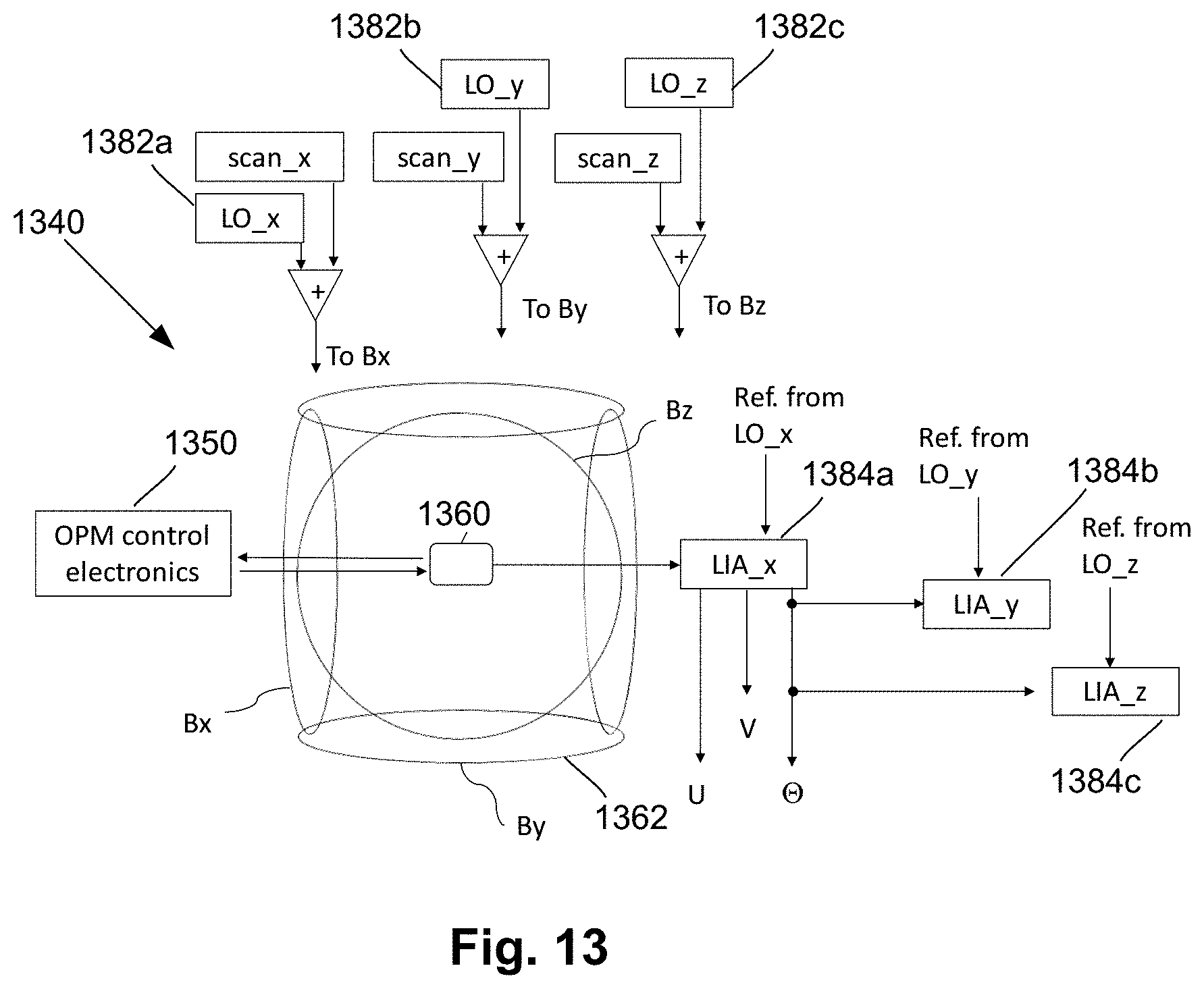


XML
uspto.report is an independent third-party trademark research tool that is not affiliated, endorsed, or sponsored by the United States Patent and Trademark Office (USPTO) or any other governmental organization. The information provided by uspto.report is based on publicly available data at the time of writing and is intended for informational purposes only.
While we strive to provide accurate and up-to-date information, we do not guarantee the accuracy, completeness, reliability, or suitability of the information displayed on this site. The use of this site is at your own risk. Any reliance you place on such information is therefore strictly at your own risk.
All official trademark data, including owner information, should be verified by visiting the official USPTO website at www.uspto.gov. This site is not intended to replace professional legal advice and should not be used as a substitute for consulting with a legal professional who is knowledgeable about trademark law.