Magnetic Field Sensor Having Unequally Spaced Magnetic Field Sensing Elements
Eagen; Jeffrey ; et al.
U.S. patent application number 16/232348 was filed with the patent office on 2020-07-02 for magnetic field sensor having unequally spaced magnetic field sensing elements. This patent application is currently assigned to Allegro MicroSystems, LLC. The applicant listed for this patent is Allegro MicroSystems, LLC. Invention is credited to Paul A. David, Jeffrey Eagen.
| Application Number | 20200209017 16/232348 |
| Document ID | / |
| Family ID | 68732640 |
| Filed Date | 2020-07-02 |


View All Diagrams
| United States Patent Application | 20200209017 |
| Kind Code | A1 |
| Eagen; Jeffrey ; et al. | July 2, 2020 |
Magnetic Field Sensor Having Unequally Spaced Magnetic Field Sensing Elements
Abstract
A magnetic field sensor for sensing a movement of a target object an include a substrate having a major planar surface and three or more magnetic field sensing elements disposed upon the major planar surface of the substrate. The three or more magnetic field sensing elements can have respective major response axes, each major response axis parallel to the major planar surface of the substrate. The three or more magnetic field sensing elements comprise first and third magnetic field sensing elements and a second magnetic field sensing element disposed between the first and third magnetic field sensing elements. A first spacing between the first and second magnetic field sensing elements is less than a second spacing between the second and third magnetic field sensing elements. No other magnetic field sensing elements are disposed between the first and third magnetoresistance elements.
| Inventors: | Eagen; Jeffrey; (Manchester, NH) ; David; Paul A.; (Bow, NH) | ||||||||||
| Applicant: |
|
||||||||||
|---|---|---|---|---|---|---|---|---|---|---|---|
| Assignee: | Allegro MicroSystems, LLC Manchester NH |
||||||||||
| Family ID: | 68732640 | ||||||||||
| Appl. No.: | 16/232348 | ||||||||||
| Filed: | December 26, 2018 |
| Current U.S. Class: | 1/1 |
| Current CPC Class: | G01D 5/147 20130101; G01P 13/045 20130101; G01M 13/021 20130101; G01P 3/488 20130101; G01D 5/245 20130101; G01D 5/145 20130101 |
| International Class: | G01D 5/245 20060101 G01D005/245; G01M 13/021 20060101 G01M013/021; G01D 5/14 20060101 G01D005/14 |
Claims
1. A magnetic field sensor for sensing a movement of a target object, the magnetic field sensor comprising: a substrate having a major planar surface; three or more magnetic field sensing elements disposed upon the major planar surface of the substrate, the three or more magnetic field sensing elements having respective major response axes, each major response axis parallel to the major planar surface of the substrate, wherein the three or more magnetic field sensing elements comprise first and third magnetic field sensing elements and a second magnetic field sensing element disposed between the first and third magnetic field sensing elements, wherein a first spacing between the first and second magnetic field sensing elements is less than a second spacing between the second and third magnetic field sensing elements, wherein there is no other magnetic field sensing element disposed between the first and third magnetic field sensing elements, wherein the three or more magnetic field sensing elements are configured to generate three or more magnetic field signals, respectively; and an electronic circuit disposed upon the substrate and coupled to the three or more magnetic field sensing elements, the electronic circuit comprising: at least one analog or digital comparator configured to compare the three or more magnetic field signals to at least one threshold value to generate three or more binary signals, respectively, wherein states of the three or more binary signals are each indicative of a position of the target object relative to the three or more magnetic field sensing elements for any movement speed of the target object including zero movement speed.
2. The magnetic field sensor of claim 1, wherein the electronic circuit further comprises: a decoder coupled to the three or more binary signals, wherein the decoder is operable to decode the three or more binary signals to generate a device output signal indicative of the position of the target object.
3. The magnetic field sensor of claim 2, wherein the first spacing is selected to result in a higher resolution of the position of the target object for selected positions of the target object.
4. The magnetic field sensor of claim 2, further comprising: a peak-to-peak amplitude detector operable to measure a peak-to-peak amplitude of at least one of the three or more magnetic field signals and operable to generate a peak-to-peak value in accordance with the measured peak-to-peak amplitude; and a threshold generator module coupled to the peak-to-peak value and operable to generate the at least one threshold value as a predetermined percentage of the peak-to-peak value.
5. The magnetic field sensor of claim 4, further comprising: a nonvolatile memory device operable to store the at least one threshold value.
6. The magnetic field sensor of claim 2, further comprising: a peak-to-peak amplitude detector operable to measure three or more peak-to-peak amplitudes of the three or more magnetic field signals, respectively; a combining module operable to generate a peak-to-peak value in accordance with a combination of the measured three or more peak-to-peak amplitudes; and a threshold generator module coupled to the peak-to-peak value and operable to generate the at least one threshold value as a predetermined percentage of the peak-to-peak value.
7. The magnetic field sensor of claim 6, further comprising: a nonvolatile memory device operable to store the at least one threshold value.
8. The magnetic field sensor of claim 2, wherein the decoder comprises: a non-volatile memory device.
9. The magnetic field sensor of claim 2, wherein the device output signal is also indicative of a speed of the movement of the target object.
10. The magnetic field sensor of claim 9, wherein the device output signal is also indicative of a direction of the movement of the target object.
11. The magnetic field sensor of claim 10, wherein the electronic circuit further comprises: an output protocol module operable to use the device output signal to generate an output protocol signal indicative of the position of the target object, and at least one of the movement speed of the target object or the direction of the movement of the target object.
12. The magnetic field sensor of claim 2, wherein the three or more magnetic field sensing elements comprise three or more magnetoresistance elements.
13. The magnetic field sensor of claim 12, wherein the three or more magnetic field sensing elements have respective maximum response axes parallel to each other.
14. The magnetic field sensor of claim 2, wherein the decoder is further operable to store a value indicative of a measured operational characteristic of the magnetic field sensor, wherein the stored value is stored during a first time period, and wherein the stored value is recalled and used during a second different time period after the first time period.
15. The magnetic field sensor of claim 2, further comprising: a magnet disposed proximate to the substrate, the magnet having at least two poles to generate a magnetic field parallel to the major planar surface of the substrate.
16. The magnetic field sensor of claim 2, wherein the major planar surface of the substrate overlaps the target object such that a line perpendicular to the major planar surface of the substrate and passing through at least one of the three or more magnetic field sensing elements intersects the target object.
17. The magnetic field sensor of claim 2, wherein the target object comprises a ring magnet having a plurality of alternating north and south poles, the target object to generate a magnetic field parallel to the major planar surface of the substrate.
18. The magnetic field sensor of claim 17, wherein the major planar surface of the substrate overlaps the target object such that a line perpendicular to the major planar surface of the substrate and passing through at least one of the three or more magnetic field sensing elements intersects the target object.
19. The magnetic field sensor of claim 2, wherein the three or more magnetic field sensing elements are arranged in a line within twenty degrees of parallel to a tangent to the movement of the target object.
20. The magnetic field sensor of claim 2, wherein the three or more magnetic field sensing elements are arranged in at least two parallel lines, each within twenty degrees of parallel to a tangent to the movement of the target object.
21. The magnetic field sensor of claim 2, wherein the three or more magnetic field sensing elements are arranged in an arc.
22. The magnetic field sensor of claim 2, wherein the three or more magnetic field sensing elements comprise a quantity of magnetic field sensing elements in a range of three to twenty magnetic field sensing elements.
23. The magnetic field sensor of claim 2, wherein the three or more magnetic field sensing elements comprise a respective three or more magnetoresistance elements.
24. The magnetic field sensor of claim 23, wherein the three or more magnetic field sensing elements have respective maximum response axes parallel to each other.
25. The magnetic field sensor of claim 2, wherein the electronic circuit further comprises: a threshold calculation module coupled to receive the three or more magnetic field signals, the threshold calculation module configured to generate the at least one threshold value indicative of an amplitude of at least one of the three or more magnetic field signals, respectively; and a non-volatile memory device operable to store the at least one threshold value, wherein the non-volatile memory device is further operable to provide the at least one threshold value to the at least one analog or digital comparator.
26. The magnetic field sensor of claim 25, wherein the at least one threshold value is stored during a time period when the electronic circuit is powered down and wherein the stored at least one threshold value is provided to the at least one analog or digital comparator when the magnetic field sensor powers up.
27. The magnetic field sensor of claim 25, wherein the at least one threshold value is stored during a first time period, and wherein the stored at least one threshold value is provided to the at least one analog or digital comparator during a second different time period after the first time period.
28. The magnetic field sensor of claim 2, wherein the three or more magnetic field sensing elements comprise three or more vertical Hall Effect elements.
29. The magnetic field sensor of claim 2, wherein the target object comprises a ferromagnetic gear configured to rotate.
30. The magnetic field sensor of claim 2, wherein the target object comprises a ferromagnetic ring magnet configured to rotate.
31. The magnetic field sensor of claim 2, wherein the three or more magnetic field sensing elements are arranged in an arc proximate to the target object, and wherein maximum response axes of the three or more magnetic field sensing elements are parallel to each other.
32. The magnetic field sensor of claim 2, wherein the three or more magnetic field sensing elements are arranged in an arc proximate to the target object, and wherein maximum response axes of the three or more magnetic field sensing elements are not parallel to each other.
33. The magnetic field sensor of claim 2, wherein the substrate overlaps the target object such that a line perpendicular to a major surface of the substrate and passing through at least one of the three or more magnetic field sensing elements intersects the target object, and a line parallel to the major planar surface of the substrate is in a direction of the target object.
34. The magnetic field sensor of claim 2, wherein the target object comprises a non-ferromagnetic conductive target object.
35. The magnetic field sensor of claim 2, wherein the electronic circuit further comprises: at least one analog-to-digital converter operable to convert the three or more magnetic field signals to generate at least one converted signal, the at least one analog or digital comparator to receive the at least one converted signal.
36. The magnetic field sensor of claim 2, wherein the target object comprises a circular magnet having a plurality of alternating north and south poles upon a major surface of the circular magnet, the target object to generate a magnetic field parallel to the major planar surface of the substrate.
37. The magnetic field sensor of claim 36, wherein the major planar surface of the substrate overlaps the target object such that a line perpendicular to the major planar surface of the substrate and passing through at least one of the three or more magnetic field sensing elements intersects the target object.
38. A method of sensing a movement of a target object, comprising: generating three or more magnetic field signals with three or more magnetic field sensing elements disposed upon a major planar surface of a substrate, the three or more magnetic field sensing elements having respective major response axes, each major response axis parallel to the major planar surface of the substrate, wherein the three or more magnetic field sensing elements comprise first and third magnetic field sensing elements and a second magnetic field sensing element disposed between the first and third magnetic field sensing elements, wherein a first spacing between the first and second magnetic field sensing elements is less than a second spacing between the second and third magnetic field sensing elements, wherein there is no other magnetic field sensing element disposed between the first and third magnetic field sensing element; and comparing the three or more magnetic field signals to at least one threshold value to generate three or more binary signals, respectively, wherein states of the three or more binary signals are each indicative of a position of the target object relative to the three or more magnetic field sensing elements for any movement speed of the target object including zero movement speed.
39. A magnetic field sensor for sensing a movement of a target object, the magnetic field sensor comprising: means for generating generate three or more magnetic field signals with three or more magnetic field sensing elements disposed upon a major planar surface of a substrate, the three or more magnetic field sensing elements having respective major response axes, each major response axis parallel to the major planar surface of the substrate, wherein the three or more magnetic field sensing elements comprise first and third magnetic field sensing elements and a second magnetic field sensing element disposed between the first and third magnetic field sensing elements, wherein a first spacing between the first and second magnetic field sensing elements is less than a second spacing between the second and third magnetic field sensing elements, wherein there is no other magnetic field sensing element disposed between the first and third magnetic field sensing element; and means for comparing the three or more magnetic field signals to at least one threshold value to generate three or more binary signals, respectively, wherein states of the three or more binary signals are each indicative of a position of the target object relative to the three or more magnetic field sensing elements for any movement speed of the target object including zero movement speed.
Description
CROSS REFERENCE TO RELATED APPLICATIONS
[0001] Not Applicable
STATEMENT REGARDING FEDERALLY SPONSORED RESEARCH
[0002] Not Applicable.
FIELD OF THE INVENTION
[0003] This invention relates generally to magnetic field sensors, and, more particularly, to magnetic field sensors having a substrate with magnetic field sensing elements thereupon that are unequally spaced.
BACKGROUND
[0004] Various types of magnetic field sensing elements are known, including Hall Effect elements and magnetoresistance elements. Magnetic field sensors generally include a magnetic field sensing element and other electronic components. Some magnetic field sensors also include a permanent magnet (a hard ferromagnetic object) in a so-called "back biased" arrangement described more fully below. Other magnetic field sensors sense motion of a magnet.
[0005] Magnetic field sensors provide an electrical signal representative of a sensed magnetic field. In some embodiments that have the magnet (back-biased arrangements), the sensed magnetic field is a magnetic field generated by the magnet, in which case, in the presence of a moving ferromagnetic object, the magnetic field generated by the magnet and sensed by the magnetic field sensor varies in accordance with a shape or profile of the moving ferromagnetic object. In contrast, magnetic field sensors that sense a moving magnet directly sense variations of magnetic field magnitude and direction that result from movement of the magnet.
[0006] Magnetic field sensors (back-biased) are often used to detect movement of features of a ferromagnetic gear, such as gear teeth and/or gear slots or valleys. A magnetic field sensor in this application is commonly referred to as a "gear tooth" sensor.
[0007] In some arrangements, the gear (a target object) is placed upon another object, for example, a camshaft in an engine. Thus, it is the rotation of both the target object (e.g., gear) and the other object (e.g., camshaft) that is sensed by detection of the moving features of the gear. Gear tooth sensors are used, for example, in automotive applications to provide information to an engine control processor for ignition timing control, fuel management, anti-lock braking systems, wheel speed sensors, and other operations.
[0008] Information provided by the gear tooth sensor to the engine control processor can include, but is not limited to, an absolute angle of rotation of a target object (e.g., a camshaft) as it rotates, a speed of the rotation, and a direction of the rotation. With this information, the engine control processor can adjust the timing of firing of the ignition system and the timing of fuel injection by the fuel injection system.
[0009] Many types of magnetic field sensors do not provide an accurate output signal (e.g., indication of absolute angle, speed, or direction of rotation) immediately upon power up, upon movement of the target object from zero rotating speed, and/or upon movement slowing to zero rotating speed, but instead provide an accurate output signal only once the target object has moved through a substantial rotation or is moving with substantial speed. For example, in one type of magnetic field sensor described in U.S. Pat. No. 6,525,531, entitled "Detection of Passing Magnetic Articles while Adapting the Detection Threshold," issued Feb. 25, 2003, a positive digital-to-analog converter (PDAC) and a negative digital-to-analog converter (NDAC) track positive and negative peaks of a magnetic field signal, respectively, for use in generating a threshold signal. A varying magnetic field signal is compared to the threshold signal. However, the outputs of the PDAC and the NDAC may not be accurate indications of the positive and negative peaks of the magnetic field signal until several cycles of the signal (i.e., signal peaks) occur (i.e., until several gear teeth have passed). This type of magnetic field sensor, which generally requires time to become fully accurate, is referred to herein as a so-called "precision rotation detector."
[0010] In contrast, a "true power on state" (TPOS) detector can provide an accurate output signal shortly after movement of a target object (e.g., camshaft) from zero rotating speed, or a low rotation speed in some applications of, for example, less than 100 rpm, or also shortly before movement slowing to zero rotating speed. Furthermore, even when the target object is not moving, the TPOS detector can provide an indication of whether the TPOS detector is in front of a tooth or a valley of a gear. However, when the target object is stationary, the conventional TPOS detector is not able to identify an absolute or relative angle of rotation of the target object. The TPOS detector can be used in conjunction with a precision rotation detector within a common integrated circuit, each providing information to the engine control processor at different times. For simplicity, TPOS detectors and precision rotation detectors are shown herein within a common integrated circuit. However, the TPOS detector or the precision rotation detector can also be used alone in separate circuits.
[0011] As described above, the conventional TPOS detector provides an accurate output signal with only a small initial rotation of the target object, and before the precision rotation detector can provide an accurate output signal. The TPOS detector can provide information to the engine control processor that can be more accurate than information provided by the precision rotation detector for time periods at the beginning and at the end of rotation of the target object (e.g., start and stop of the engine and camshaft), but which may be less accurate when the object is rotating at speed. For magnetic field sensor arrangements that have both a TPOS detector and a precision rotation detector within a common integrated circuit, when the object is not rotating or rotating slowly, the engine control processor can use the TPOS detector. When rotating at speed, the engine control processor can primarily use rotation information provided by the precision rotation detector. In most conventional applications, once the magnetic field sensor switches to use the precision rotation detector, it does not return to use the TPOS detector until the target object stops rotating or nearly stops rotating.
[0012] A conventional TPOS detector is described in U.S. Pat. No. 7,362,094, entitled "Method and Apparatus for Magnetic Article Detection," issued Apr. 22, 2008. The conventional TPOS detector includes a comparator for comparing the magnetic field signal to a fixed, often trimmed, threshold signal. The conventional TPOS detector can be used in conjunction with and can detect rotational information about a TPOS cam (like a gear), which is disposed upon a target object, e.g., an engine camshaft, configured to rotate.
[0013] An example of an output signal from a conventional TPOS detector has at least two states, and typically a high and a low state. The state of the conventional TPOS output signal is high at some times and low at other times as the target object rotates, in accordance with features on the TPOS cam (or gear) attached to the target object.
[0014] Similarly, an output signal from a conventional precision rotation detector also has at least two states, and typically a high and a low state. The state of the conventional precision rotation detector output signal is high at some times and low at other times as the target object rotates, also in accordance with features on the TPOS cam (or gear) attached to the target object
[0015] As described above, conventional TPOS detectors have the ability to differentiate a gear tooth from a gear valley (i.e., gear "features"), and to make such detection when the gear is rotating and when the gear is not rotating. In contrast, some conventional precision rotation detectors have the ability to differentiate a gear tooth from a gear valley when the gear is rotating, but not when the gear is stationary. Detectors that can identify a gear tooth from a valley are sometimes referred to as "tooth detectors." Thus, TPOS detectors are usually tooth detectors. Some precision rotation detectors can also be tooth detectors.
[0016] While detection of gear teeth can be used by some magnetic field sensors, other magnetic field sensors can sense passing magnetic poles of a ring magnet (i.e., features). Thus, as used herein, the term "feature detector" is used to describe either a tooth detector or a detector of magnetic poles.
[0017] Some other conventional precision rotation detectors are unable to differentiate a gear tooth from a valley (or a north pole from a south pole of a ring magnet), but instead, can differentiate an edge of a tooth of the gear from the tooth or the valley. Such detectors are sometimes referred to as "edge detectors." Usually, TPOS detectors are not edge detectors. However, some precision rotation detectors can be edge detectors.
[0018] Conventional magnetic field sensors, even TPOS detectors, are unable to identify An accurate position (e.g., a rotation angle) of a target object when the target object is not moving.
[0019] It would be desirable to provide a magnetic field sensor that can achieve an accurate output signal that can more accurately identify a position of a target object, even when the target object is stationary.
SUMMARY
[0020] The present invention provides a magnetic field sensor that can achieve an accurate output signal that can more accurately identify a position of a target object, even when the target object is stationary.
[0021] In accordance with an example useful for understanding an aspect of the present invention, a magnetic field sensor for sensing a movement of a target object can include a substrate having a major planar surface. The magnetic field sensor can also include three or more magnetic field sensing elements disposed upon the major planar surface of the substrate, the three or more magnetic field sensing elements having respective major response axes, each major response axis parallel to the major planar surface of the substrate. The three or more magnetic field sensing elements include first and third magnetic field sensing elements and a second magnetic field sensing element disposed between the first and third magnetic field sensing elements. A first spacing between the first and second magnetic field sensing elements is less than a second spacing between the second and third magnetic field sensing elements. There is no other magnetic field sensing element disposed between the first and third magnetic field sensing elements. The three or more magnetic field sensing elements are configured to generate three or more magnetic field signals. The magnetic field sensor can also include an electronic circuit disposed upon the substrate and coupled to the three or more magnetic field sensing elements. The electronic circuit can include at least one analog or digital comparator configured to compare the three or more magnetic field signals to at least one threshold value to generate three or more binary signals, respectively, wherein states of the three or more binary signals are each indicative of a position of the target object relative to the three or more magnetic field sensing elements for any movement speed of the target object including zero movement speed.
[0022] In accordance with an example useful for understanding another aspect of the present invention, a method of sensing a movement of a target object can include generating three or more magnetic field signals with three or more magnetic field sensing elements disposed upon a major planar surface of a substrate. The three or more magnetic field sensing elements can have respective major response axes, each major response axis parallel to the major planar surface of the substrate. The three or more magnetic field sensing elements comprise first and third magnetic field sensing elements and a second magnetic field sensing element disposed between the first and third magnetic field sensing elements. A first spacing between the first and second magnetic field sensing elements is less than a second spacing between the second and third magnetic field sensing elements. There is no other magnetic field sensing element disposed between the first and third magnetic field sensing element. The method can also include comparing the three or more magnetic field signals to at least one threshold value to generate three or more binary signals, respectively, States of the three or more binary signals are each indicative of a position of the target object relative to the three or more magnetic field sensing elements for any movement speed of the target object including zero movement speed.
[0023] In accordance with an example useful for understanding another aspect of the present invention, a magnetic field sensor for sensing a movement of a target object can include means for generating generate three or more magnetic field signals with three or more magnetic field sensing elements disposed upon a major planar surface of a substrate. The three or more magnetic field sensing elements can have respective major response axes, each major response axis parallel to the major planar surface of the substrate, wherein the three or more magnetic field sensing elements comprise first and third magnetic field sensing elements and a second magnetic field sensing element disposed between the first and third magnetic field sensing elements. A first spacing between the first and second magnetic field sensing elements is less than a second spacing between the second and third magnetic field sensing elements. There is no other magnetic field sensing element disposed between the first and third magnetic field sensing element. The magnetic field sensor can also include means for comparing the three or more magnetic field signals to at least one threshold value to generate three or more binary signals, respectively, wherein states of the three or more binary signals are each indicative of a position of the target object relative to the three or more magnetic field sensing elements for any movement speed of the target object including zero movement speed.
BRIEF DESCRIPTION OF THE DRAWINGS
[0024] The foregoing features of the invention, as well as the invention itself may be more fully understood from the following detailed description of the drawings, in which:
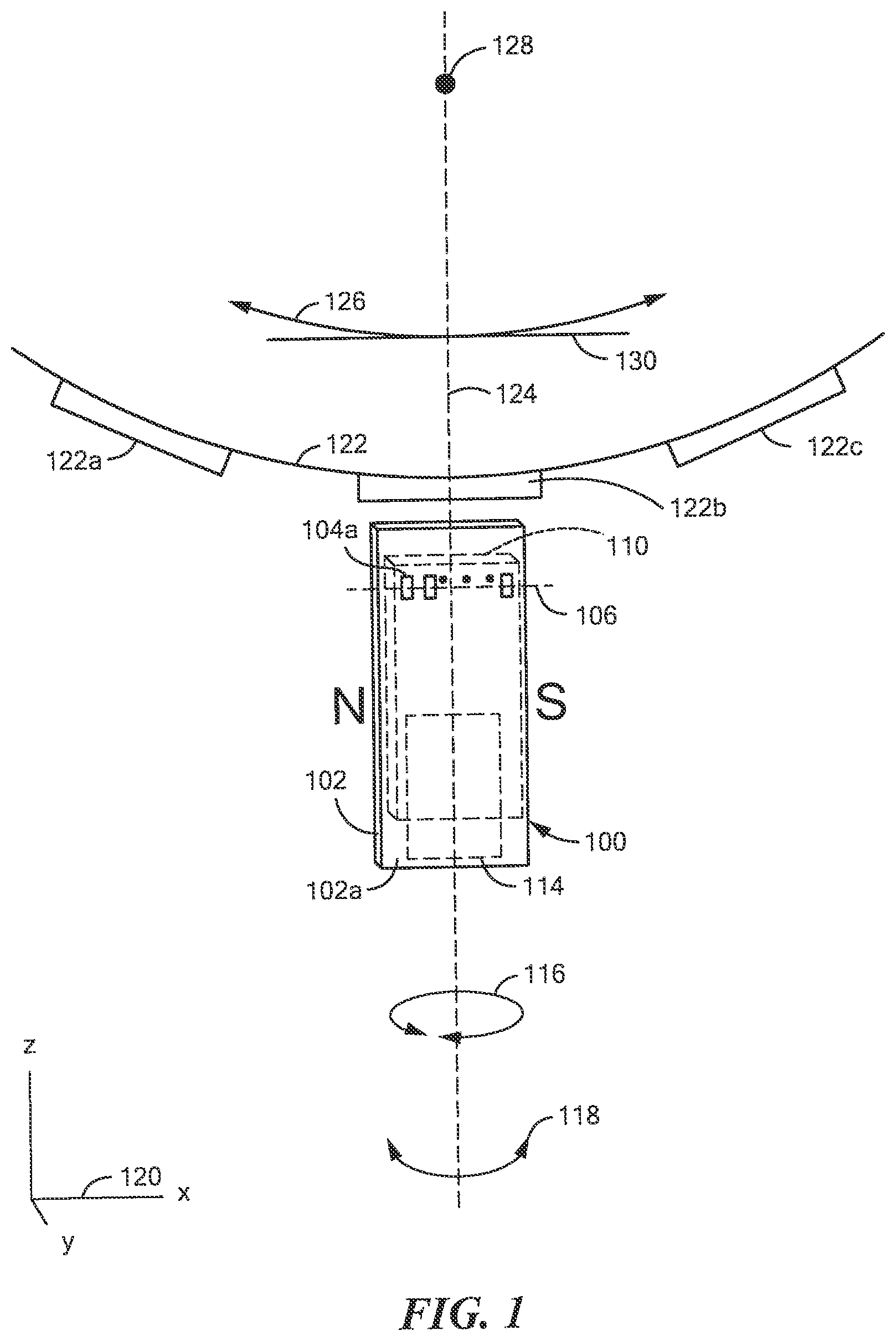
[0025] FIG. 1 is a block diagram showing an example of a magnetic field sensor having a three or more magnetic field sensing elements and an electronic circuit both disposed on a substrate, and also having a magnet, wherein the substrate is proximate to a target object in the form of a gear;
[0026] FIG. 2 is a block diagram showing an example of another magnetic field sensor having a three or more magnetic field sensing elements and an electronic circuit both disposed on a substrate, and having a magnet different than the magnet of FIG. 3, wherein the substrate is proximate to a target object in the form of a gear;
[0027] FIG. 3 is a block diagram showing an illustrative three or more magnetic field sensing elements and an illustrative electronic circuit that can be used as the three or more magnetic field sensing elements and the electronic circuit of FIGS. 1 and 2 and others;
[0028] FIG. 4 is a block diagram showing an illustrative three or more magnetic field sensing elements and another illustrative electronic circuit that can be used as the three or more magnetic field sensing elements and the electronic circuit of FIGS. 1 and 2 and others;
[0029] FIG. 5 is a block diagram showing an illustrative three or more magnetic field sensing elements and another illustrative electronic circuit that can be used as the three or more magnetic field sensing elements and the electronic circuit of FIGS. 1 and 2 and others, the electronic circuit having a threshold calculation module;
[0030] FIG. 6 is a block diagram showing an illustrative threshold calculation module that can be used as the threshold calculation module of FIG. 5;
[0031] FIGS. 7-10 show illustrations of examples of three or more magnetic field sensing elements, here magnetoresistance elements, having unequal spacings that can be used as the three or more magnetic field sensing elements of FIGS. 1-5 and others;
[0032] FIG. 11 is a block diagram showing an example of a magnetic field sensor having a three or more magnetic field sensing elements and an electronic circuit both disposed on a substrate, and also having a magnet, wherein the substrate overlaps a target object in the form of a gear;
[0033] FIG. 12 is a block diagram showing an example of another magnetic field sensor having a three or more magnetic field sensing elements and an electronic circuit both disposed on a substrate, and also having a magnet different than the magnet of FIG. 11, wherein the substrate overlaps a target object in the form of a gear;
[0034] FIG. 13 is a block diagram showing an example of a magnetic field sensor having a three or more magnetic field sensing elements and an electronic circuit both disposed on a substrate, wherein the substrate is proximate to a target object in the form of a ring magnet;
[0035] FIG. 14 is a block diagram showing an example of a magnetic field sensor having a three or more magnetic field sensing elements and an electronic circuit both disposed on a substrate, wherein the substrate overlaps a target object in the form of a ring magnet;
[0036] FIG. 15 is a block diagram showing an illustrative three or more magnetic field sensing elements disposed in and arc, which can be used as the three or more magnetic field sensing elements of figures above and below;
[0037] FIG. 16 is a block diagram showing a pair of magnetoresistance elements that can be used as one of the three or more magnetic field sensing elements of figures above and below;
[0038] FIG. 17 is a block diagram showing the pair of magnetoresistance elements of FIG. 16 coupled in a bridge arrangement;
[0039] FIG. 18 is a block diagram showing an example of a magnetic field sensor having a three or more magnetic field sensing elements and an electronic circuit, both disposed on a substrate, wherein the substrate overlaps a target object in the form of a circular or disk magnet; and
[0040] FIG. 19 is a top view showing a packed integrated circuit housing any of the substrates above.
DETAILED DESCRIPTION
[0041] Before describing the present invention, some introductory concepts and terminology are explained.
[0042] As used herein, the term "magnetic field sensing element" is used to describe a variety of electronic elements that can sense a magnetic field. The magnetic field sensing element can be, but is not limited to, a Hall effect element, a magnetoresistance element, or a magnetotransistor. As is known, there are different types of Hall effect elements, for example, a planar Hall element, a vertical Hall element, and a Circular Vertical Hall (CVH) element. As is also known, there are different types of magnetoresistance elements, for example, a semiconductor magnetoresistance element such as Indium Antimonide (InSb), a giant magnetoresistance (GMR) element, for example, a spin valve, an anisotropic magnetoresistance element (AMR), a tunneling magnetoresistance (TMR) element, and a magnetic tunnel junction (MTJ). The magnetic field sensing element may be a single element or, alternatively, may include two or more magnetic field sensing elements arranged in various configurations, e.g., a half bridge or full (Wheatstone) bridge. Depending on the device type and other application requirements, the magnetic field sensing element may be a device made of a type IV semiconductor material such as Silicon (Si) or Germanium (Ge), or a type III-V semiconductor material like Gallium-Arsenide (GaAs) or an Indium compound, e.g., Indium-Antimonide (InSb).
[0043] As is known, some of the above-described magnetic field sensing elements tend to have an axis of maximum sensitivity parallel to a substrate that supports the magnetic field sensing element, and others of the above-described magnetic field sensing elements tend to have an axis of maximum sensitivity perpendicular to a substrate that supports the magnetic field sensing element. In particular, planar Hall elements tend to have axes of sensitivity perpendicular to a substrate, while metal based or metallic magnetoresistance elements (e.g., GMR, TMR, AMR) and vertical Hall elements tend to have axes of sensitivity parallel to a substrate.
[0044] As used herein, the term "magnetic field sensor" is used to describe a circuit that uses a magnetic field sensing element, generally in combination with other circuits. Magnetic field sensors are used in a variety of applications, including, but not limited to, an angle sensor that senses an angle of a direction of a magnetic field, a current sensor that senses a magnetic field generated by a current carried by a current-carrying conductor, a magnetic switch that senses the proximity of a ferromagnetic object, a rotation detector that senses passing ferromagnetic articles, for example, magnetic domains of a ring magnet or a ferromagnetic target (e.g., gear teeth) where the magnetic field sensor is used in combination with a back-biased or other magnet, and a magnetic field sensor that senses a magnetic field density of a magnetic field.
[0045] The terms "parallel" and "perpendicular" are used in various contexts herein. It should be understood that the terms parallel and perpendicular do not require exact perpendicularity or exact parallelism, but instead it is intended that normal manufacturing tolerances apply, which tolerances depend upon the context in which the terms are used. In some instances, the term "substantially" is used to modify the terms "parallel" or "perpendicular." In general, use of the term "substantially" reflects angles that are beyond manufacturing tolerances, for example, within +/- ten degrees.
[0046] As used herein, the term "processor" is used to describe an electronic circuit that performs a function, an operation, or a sequence of operations. The function, operation, or sequence of operations can be hard coded into the electronic circuit or soft coded by way of instructions held in a memory device. A "processor" can perform the function, operation, or sequence of operations using digital values or using analog signals.
[0047] In some embodiments, the "processor" can be embodied in an application specific integrated circuit (ASIC), which can be an analog ASIC or a digital ASIC. In some embodiments, the "processor" can be embodied in a microprocessor with associated program memory. In some embodiments, the "processor" can be embodied in a discrete electronic circuit, which can be analog or digital.
[0048] As used herein, the term "module" can be used to describe a "processor." However, the term "module" is used more generally to describe any circuit that can transform an input signal into an output signal that is different than the input signal.
[0049] A processor can contain internal processors or internal modules that perform portions of the function, operation, or sequence of operations of the processor. Similarly, a module can contain internal processors or internal modules that perform portions of the function, operation, or sequence of operations of the module.
[0050] While electronic circuits shown in figures herein may be shown in the form of analog blocks or digital blocks, it will be understood that the analog blocks can be replaced by digital blocks that perform the same or similar functions and the digital blocks can be replaced by analog blocks that perform the same or similar functions. Analog-to-digital or digital-to-analog conversions may not be explicitly shown in the figures, but should be understood.
[0051] In particular, it should be understood that a so-called comparator can be comprised of an analog comparator having a two state output signal indicative of an input signal being above or below a threshold level (or indicative of one input signal being above or below another input signal). However, the comparator can also be comprised of a digital circuit having an output signal with at least two states indicative of an input signal being above or below a threshold level (or indicative of one input signal being above or below another input signal), respectively, or a digital value above or below a digital threshold value (or another digital value), respectively.
[0052] As used herein, the term "predetermined," when referring to a value or signal, is used to refer to a value or signal that is set, or fixed, in the factory at the time of manufacture, or by external means, e.g., programming, thereafter. As used herein, the term "determined," when referring to a value or signal, is used to refer to a value or signal that is identified by a circuit during operation, after manufacture.
[0053] As used herein, the term "amplifier" is used to describe a circuit element with a gain greater than one, less than one, or equal to one.
[0054] As used herein, the terms "line" and "linear" are used to describe either a straight line or a curved line. The line can be described by a function having any order less than infinite.
[0055] Giant magnetoresistance (GMR) elements are shown and described in conjunction with figures below. However, in other embodiments, the GMR elements can be replaced by tunneling magnetoresistance (TMR) elements. In still other embodiments, the GMR elements can be replaced by planar or vertical Hall effect elements or other types or magnetic field sensing elements with modifications that will be understood.
[0056] Referring to FIG. 1, a magnetic field sensor 100 is responsive to a gear 122 having gear teeth, e.g., gear teeth 122a, 122b, 122c. The magnetic field sensor 100 can include a plurality of, i.e., three or more, magnetic field sensing elements, e.g., 104a, coupled to an electronic circuit 114. In some embodiments, ones of the magnetic field sensing elements, e.g., 104a, are separated in a direction along an axis 106 between outer ones of the three or more magnetic field sensing elements by a distance between about 0.5 millimeters and about 2.5 millimeters. In general, the spacing can be selected to be between about 0.25 and 2.0 times a full cycle of features of the target object (e.g., outer edges of a tooth and a valley or outer edges of north and south poles).
[0057] The spacings between magnetic field sensing elements are not equal. Examples of the unequal spacings are described below in conjunction with FIGS. 7-10.
[0058] The three or more magnetic field sensing elements, e.g., 104a, and the electronic circuit 114 can be disposed upon a major surface 102a of (i.e., integrated within or upon) a substrate 102.
[0059] While three or more magnetic field sensing element to generate three or more magnetic field signals are described herein, there can be three or any integer number greater than three magnetic field sensing elements to generate three or any integer number greater than three magnetic field signals in order to achieve the unequal spacings between magnetic field sensing elements.
[0060] The magnetic field sensor 100 can also include a magnet 110. The magnet 110 is configured to generate a magnetic field, which is generally directed along an axis 106 at the position of the three or more magnetic field sensing elements, e.g., 104a, and is generally parallel to the major surface 102a of the substrate 102.
[0061] The three or more magnetic field sensing elements, e.g., 104a, have respective maximum response axes parallel to the major surface 102a of the substrate 102. In some embodiments, the maximum response axes are parallel to each other. In some embodiments, the maximum response axes are substantially parallel to the axis 106. In other embodiments, the maximum response axes are substantially perpendicular to the axis 106.
[0062] A line perpendicular to the major surface 102a of the substrate (i.e., into the page) intersects the magnet 110 and does not intersect the gear 122. Furthermore, the three or more magnetic field sensing elements, e.g., 104a, are disposed at a position such that the axis (e.g., 106) passing through the three or more magnetic field sensing elements, e.g., 104a, does not intersect the gear 122. In some embodiments, the axis (e.g., 106) passing through the three or more magnetic field sensing elements, e.g., 104a, is substantially parallel to a tangent 130 to a direction of movement, e.g., 126, of the gear 122.
[0063] In the embodiment shown, a line between north (N) and south (S) poles of the magnet 110 is substantially parallel to the major surface 102a of the substrate 102, and is substantially parallel to the axis (e.g., 106) passing through the three or more magnetic field sensing elements, e.g., 104a. In some embodiments, the line between north and south poles does not intersect the ferromagnetic target object 122.
[0064] The magnetic field sensor 100 can use the three or more magnetic field sensing elements, e.g., 104a, to generate a respective three or more magnetic field signals.
[0065] The electronic circuit 114 is configured to generate an output signal (not shown). An example of an electronic circuit is described more fully below in conjunction with FIGS. 3-6. Let is suffice here to say that the electronic circuit 114 is configured to compare each one of the three or more magnetic field signals generated by the three or more magnetic field sensing elements, e.g., 104a, to a respective threshold signal to generate a three or more binary signals. States of the three or more binary signals are indicative of a position of the ferromagnetic target object 122, and, in particular, a position of an edge of a gear tooth or an edge of a gear valley, relative to the three or more magnetic field sensing elements. It will be apparent that the magnetic field sensor 100 can operate as an edge detector, a tooth detector, or both.
[0066] An output signal, when the gear 122 is rotating, can be indicative of the position of the target object 122 and may also be indicative of speed of rotation of the target object 122 and may also be indicative of a direction of rotation of the target object 122. The magnetic field sensor 100 is able to provide a TPOS function, and, when the gear 122 is stationary, is able to identify whether individual ones of the three or more magnetic field sensing elements, e.g., 104a, are proximate to a gear tooth or a valley in the gear 122.
[0067] The magnetic field sensor 100 can be able to identify a direction of rotation of the target object 122 by way of a detected progression of magnetic field changes sensed by the three or more magnetic field sensing elements, e.g., 104a as the target object 122 moves (i.e. rotates.).
[0068] The magnet 110 can be comprised of one uniform material, and can have no central core. In some embodiments, the magnet 110 can be rectangular.
[0069] Each respective one of the three or more magnetic field signals is responsive to a magnetic field generated by the magnet 110 and influenced by a position of features of a ferromagnetic target object, e.g., gear teeth 122a, 122b, 122c, relative to a position of each respective one of the three or more magnetic field sensing elements. The ferromagnetic target object 122 is configured to move in two directions 126 of movement about an axis of rotation 128. The three or more magnetic field sensing elements, e.g., 104a, are disposed along the axis 106, which is substantially parallel to the tangent 130.
[0070] In some alternate embodiments, the three or more magnetic field sensing elements, e.g., 104as, are disposed along an arc rather than along the line 106. A diameter of the arc can be the same as or similar to a diameter of the gear 122. The arc can be curved in the same direction as the circumference of the gear, or in the other direction. When disposed in an arc, maximum response axes of the magnetic field sensing elements can be parallel to each other, or they may not be parallel to each other. An arc arrangement is shown below in conjunction with FIG. 15.
[0071] In some embodiments, the three or more magnetic field sensing elements, e.g., 104a, have a respective three or more maximum response axes parallel to each other. In some embodiments, the maximum response axes are substantially parallel to the axis 106. In other embodiments, the maximum response axes are substantially perpendicular to the axis 106.
[0072] The magnetic field sensor 100 can be rotated in a direction 116 to a next position one hundred eighty degrees apart from the position shown, with no degradation of performance. However, intermediate rotations may result in a degradation of performance.
[0073] The magnetic field sensor 100 can be rotated in a direction of and arrow 118 with a center of rotation anywhere along a line 124, through approximately +/- twenty degrees, without substantial degradation of performance.
[0074] In some embodiments, the three or more magnetic field sensing elements, e.g., 104a, are magnetoresistance elements. In other embodiments, the three or more magnetic field sensing elements are Hall effect elements, e.g., vertical Hall effect elements. However, it is advantageous to use magnetic field sensing elements for which respective axes of maximum sensitivity are parallel to the axis 106.
[0075] Referring now to FIG. 2, in which like elements of FIG. 1 are shown having like reference designations, a magnetic field sensor 200 is like the magnetic field sensor 100 of FIG. 1. However, the magnetic field sensor 200 has a different magnet 202 for which a line between north (N) and south (S) poles of the magnet 202 is substantially parallel to the major surface 102a of the substrate 102, and substantially perpendicular to the axis (e.g., 106) passing through the three or more magnetic field sensing elements, e.g., 104a. In some embodiments, the line between the north and south poles of the magnet 102 is in a direction toward the gear 122, parallel to the axis 124, and intersects the gear 122.
[0076] Referring now to FIG. 3, an electronic circuit 300 can be the same as or similar to electronic circuit 114 of FIGS. 1 and 2 and can be coupled to three or more magnetoresistance elements, e.g., 302, which can be the same as or similar to the three or more magnetic field sensing elements, e.g., 104a, of FIGS. 1 and 2.
[0077] The electronic circuit 300 can include a three or more electronic channels, of which a channel having a magnetoresistance element 302 and a fixed resistor 304 is but one example. The three or more electronic channels can be coupled to receive a voltage from a voltage generating source 306. Taking the magnetoresistance element 302 and the fixed resistor 304, which form a voltage divider, as being representative of elements of other ones of the electronic channels, a voltage signal 308 (also referred to as a parallel signal in view of the parallel channels) can be generated at the junction between the magnetoresistance element 302 and a fixed resistor 304. The voltage signal 308 has a value representative of a magnitude of the magnetic field experienced by the magnetoresistance element 302. Other ones of the electronic channels generate voltage signals having values representative of magnetic fields experienced by other ones of the magnetoresistance elements.
[0078] In some embodiments, a quantity of the magnetoresistance elements can be in the range of three to twenty.
[0079] In other embodiments, the voltage generating source 306 can be replaced with a current generating source or with separate current generating sources to drive each resistor divider, e.g., 302, 304. In some embodiments, the separate current generating sources can be separate controlled legs of current mirrors, each having the same reference leg.
[0080] The voltage signal 308 can be received by an amplifier 310. The amplifier 310 can be configured to generate an amplified signal 310a. A comparator 312 can be coupled to receive the amplified signal 310a, coupled to receive a threshold signal 314, and configured to generate a comparison signal 312a (i.e., a binary, two-state, signal).
[0081] In some other embodiments, the amplifiers, e.g., 310, are not used.
[0082] A decoder 314, for example, a nonvolatile memory device, for example, an electrically erasable read only memory (EEPROM), can be coupled to receive three or more such comparison signals at a multi-bit parallel signal. The decoder 314 can produce a decoded signal 314a, which can be a single bit (e.g., serial) output signal or a multi-bit (e.g., parallel) output signal. The decoded signal 314a can have a value, i.e., a digital value, representative of a position of a gear tooth relative to the three or more magnetoresistance elements, for example, a position of the gear tooth 122b of FIG. 1 relative to a position of the three or more magnetic field sensing elements shown in FIG. 1. Thus, states of the signal 314a are representative of a gear tooth, e.g., 122b, being proximate to one or more of the three or more magnetic field sensing elements and others of the three or more magnetic field sensing elements being proximate to a valley of the gear 122.
[0083] It will be appreciated that the decoder 314 can act as a look-up table, and can provide any desired mapping of the binary signal, e.g., 312a, to output signal 314a. The same electronic circuit can be applied to both the magnetic field sensor 100 of FIG. 1 and to the magnetic field sensor 200 of FIG. 2, but perhaps with different look up tables stored in the decoder 314.
[0084] In other embodiments, the decoder 314 can be a processor, a module, or a plurality of interconnected gates.
[0085] The decoded signal 314a can be indicative of a position of the target object 122, and, can also be indicative of a speed of rotation and/or a direction of rotation of the ferromagnetic target object, e.g., 122 of FIG. 1.
[0086] In some embodiments, the decoded signal 314a is coupled to an output protocol module 316. The output protocol module 316 is configured to generate a formatted signal 316a in a selected one of a plurality of formats including, but not limited to, a SENT format, an I2C format, a PWM format, or a binary format.
[0087] The formatted signal 316a is indicative of the position of the target object 122, whether moving or not moving, and thus, can also be indicative of a speed of rotation and/or a direction of rotation of the ferromagnetic target object, e.g., 122 of FIG. 1. To this end, the output protocol module 316 can use the decoded signal 314a to identify the speed of rotation and/or the direction of rotation of the ferromagnetic target object.
[0088] Certain digital values of the signal 314a may be indicative of a center (or an edge) of a target feature (e.g., gear tooth) being proximate to particular ones of the three or more magnetoresistance elements, and certain other digital values of the signal 314a may be indicative of the center (or the edge) of the target feature being proximate to other particular ones of the three or more magnetoresistance elements.
[0089] While the electronic circuit 300 is shown to have a plurality of simple voltage dividers, e.g., a voltage divider formed from the magnetoresistance element 302 with the fixed resistor 304, in other embodiments, each channel can use a different arrangement, for example, a Wheatstone (full) bridge having two or more magnetoresistance elements.
[0090] In still other embodiments, each one of the electronic channels can use a respective Hall effect element, e.g., a respective vertical Hall effect element. As is known, a Hall element can receive, i.e., can be driven by, either a voltage source or a current source, and the Hall effect element can generate, from two output signal nodes, a differential output signal. It should be apparent how the electronic circuit 300 can be modified to use Hall effect elements instead of magnetoresistance elements.
[0091] While a plurality of comparators (e.g., 312) is shown, in other embodiments, there can be one or more comparators that are time multiplexed to provide a serial digital channel. Similarly, while a three or more amplifiers 310 is shown, in other embodiments, one or more amplifiers can be time multiplexed to provide the serial channel. A multiplexed arrangement is described below in conjunction with FIGS. 4 and 5.
[0092] Referring now to FIG. 4, in which like elements of FIG. 3 are shown having like reference designations, the parallel signal channels, e.g., 306, can be coupled to an N:1 multiplexer 402 to generate a serial signal 402a, comprised to sequential ones of the parallel signal channels, e.g., 308. Accordingly, a 1:N multiplexer 401 can power the three or more magnetoresistance elements sequentially, one or more at a time.
[0093] An amplifier 404 can be coupled to the serial signal 402a and can generate a serial amplified signal 404a.
[0094] A comparator 408 can be coupled to the amplified serial signal 404a, can receive a threshold signal 408, and can generate a serial comparison signal 312a (i.e., a series of binary, two-state, values).
[0095] Digital registers 410 can be coupled to the serial comparison signal 406a and can compose a parallel comparison signal 410a similar to that which is generated by the comparators, e.g., 312 of FIG. 3.
[0096] A decoder 412 can be the same as or similar to the decoder 314 of FIG. 3. An output format module 416 can be the same as or similar to the output format module 316 of FIG. 3.
[0097] A sequence generator 418 can generate a sequence signal 416a to control the sequencing to the N:1 multiplexer 402 and the registers 410 and also to control a sequencing of the 1:N multiplexer 401. The 1:N multiplexer 401 can provide power to one or more of the magnetoresistance elements , e.g., 302, at a time. This arrangement can reduce operational power consumption.
[0098] Referring now to FIG. 5, in which like elements of FIGS. 3 and 4 are shown having like reference designations, an electronic circuit 500 can be the same as or similar to electronic circuit 114 of FIGS. 1 and 2, coupled to a three or more magnetoresistance elements, which can be the same as or similar to the three or more magnetic field sensing elements, e.g., 104a, of FIGS. 1 and 2.
[0099] The electronic circuit 500 can include a three or more electronic channels, of which a channel having the magnetoresistance element 302 and a fixed resistor 304 is but one example.
[0100] An analog-to-digital converter (ADC) 512 can be coupled to receive the serial signal 402a and can generate a converted signal 502a, which can be comprised of sequential parallel sets of digital bits indicative of amplitudes of signals generated by the three or more magnetoresistance elements, e.g., 302.
[0101] A position calculation module 504 (e.g., a processor) can be coupled to receive the converted signal 504a. In particular, a digital comparator 506 within the position calculation module 504 can be coupled to receive the converted signal 502a. The digital comparator 506 can also be coupled to receive one or more digital threshold values 522a and can be configured to generate a comparison signal 506a. In some embodiments, the comparison signal 506a can be a sequential set of single bit binary values.
[0102] Registers 508 can be coupled to the comparison signal and can assemble the bits into a parallel comparison signal 508a, similar to the parallel comparison signal 410a of FIG. 4.
[0103] A decoder 514, e.g., a nonvolatile memory device, for example, an EEPROM, can be coupled to receive the parallel comparison signal 508a. The decoder 514 can include a lookup table 518 to receive the parallel comparison signal 508a and can generate a decoded signal 518a, which can be a single bit signal or a multi-bit signal. The decoded signal 514a can be similar to the decoded signal 414a of FIG. 4.
[0104] The decoded signal 514a can be indicative of a position, a speed of rotation, and/or a direction of rotation of the ferromagnetic target object, e.g., 122 of FIG. 1.
[0105] An output protocol module 520 can receive the decoded signal 514a and can generate a formatted signal 520a, which can be the same as or similar to the formatted signal 416a of FIG. 4.
[0106] The formatted signal 514a can be indicative of a position, speed of rotation, and/or a direction of rotation of the ferromagnetic target object, e.g., 122 of FIG. 1. To this end, the output protocol module 510 can use the signal 508a to identify the speed of rotation and/or the direction of rotation of the ferromagnetic target object.
[0107] In some embodiments, the position calculation module 510 can also include a threshold calculation module 512 coupled to receive the serial converted signal 504a, described more fully below in conjunction with FIG. 6.
[0108] Let it suffice here to say that, in operation, the threshold calculation module 512 can identify desired threshold values, e.g., 522a, to use as inputs to the digital comparator, e.g., 506. For example, in some embodiments, the threshold calculation module 514 can calculate positive and negative peak values of the converted signal 504a associated with ones of the voltage signals, e.g., 308., can compute peak-to-peak values, and can compute respective threshold values to be desired percentages of the peak-to peak values. For example, in some embodiments, calculated thresholds can switch between approximately sixty percent and approximately forty percent of the peak-to-peak values the voltage signals, e.g., 308. Accordingly, the position calculation module 510 can store in a threshold storage region 516 of the decoder 514, the calculated threshold values, and can supply the calculated threshold values from the threshold storage area 516 to the digital comparator, e.g., 506.
[0109] With the above arrangement, after a power down to the electronic circuit 500, upon powering up again, the stored threshold values can be rapidly used, resulting in a faster power up response time.
[0110] In some embodiments, the position calculation module 510 can also include a sequence/vibration detection module 522 coupled to the decoded signal 514a. The sequence/vibration detection module 522 can be operable to detect a proper sequence of the features (e.g., gear teeth) of the target object moving past the three or more magnetoresistance elements, e.g., 302 of FIGS. 4 and 5, in sequence. If an improper sequence is detected, then a vibration of the target object 122 of FIGS. 1 and 2 may be suspected. If a vibration is detected, the sequence/vibration detection module 522 can send a sequence control signal 522a to sequence generator 524, which can alter sequence signal 524a to change the sequence used by the N:1 multiplexer 502. The altered sequence can essentially repeat selection of one or more of the three of more magnetoresistance elements, e.g., 302, providing a recheck of the improper sequence previously detected. Furthermore, if a vibration is detected, the sequence/vibration detection module 522 can generate a vibration detection signal 522b that can alter the formatted signal 520a.
[0111] In some embodiments, the sequence/vibration detection module 522 is also operable to detect a rate of movement of the target object, e.g., 122 of FIGS. 1 and 2, by way of the decoded signal 514a. If the target object moves slowly, then the sequence generator 524 can alter the sequence control signal 524a to slow down the rate at which the N:1 multiplexer and other elements sample the signals generated by the three or more magnetoresistance elements. In some embodiments, the sampling rate is proportional to the rate of movement of the target object. In other embodiments, the sequence generator 524 can provide discrete sampling rates, for example, two sampling rates, e.g., fast and slow, in accordance with a rate threshold of the rate of movement of the target object.
[0112] While the threshold storage module 516 is shown to be within the position calculation module 510, in other embodiments, the threshold storage module 516 is outside of the position calculation module 510.
[0113] Some other embodiments are a combination of parts of FIGS. 3, 4, and 5.
[0114] Referring now to FIG. 6, a threshold calculation module 600 can be the same as or similar to the threshold calculation module 512 of FIG. 5.
[0115] The threshold calculation module 600 can include a peak-to-peak detector 604 to identify one or more peak-to peak values of a respective one or more of the time multiplexed signals carried in a converted signal 602, which can be similar to the converted signal 504a of FIG. 5.
[0116] Peak-to-peak values 604a associated with each one of the three or more magnetoresistance elements, e.g., 302, can be temporarily stored in registers 606.
[0117] Optionally, the stored peak-to-peak values 606a can be combined, for example, averaged to generate and average peak-to-peak value 608a, to generate a combined peak-to-peak value 608a
[0118] A threshold generator module 610 can convert the combined peak-to-peak value 608a to generate a threshold value 610a. For example, in some embodiments, the threshold value 610a can be a predetermined percentage of the combined peak-to-peak value 608a, for example, forty percent, fifty percent, or sixty percent of the combined peak-to-peak value 608a. It should be apparent that this arrangement provides the same threshold value 610a for all magnetoresistance elements, e.g., 302, that are used in the combining of the combining module 608.
[0119] In other arrangements, the combining module 608 is not provided, and instead, the peak to peak values 606a associated with the magnetoresistance elements separately can be provided to the threshold generator module 610. In this arrangement, the threshold generator module 610 can generate separate threshold values associated with the three or more magnetoresistance elements, e.g., 302 of FIGS. 3-5. The separate threshold values can be provided sequentially in the threshold signal 522a of FIG. 5.
[0120] Referring now to FIG. 7, three or more magnetoresistance elements 700, here twelve magnetoresistance elements, can be arranged with unequal spacing along a line 704, such that a group 702 of the magnetoresistance elements 700 is more closely spaced than other ones of the magnetoresistance elements 700. Features, e.g., gear teeth, of a target object can be stationary with respect to the three or more magnetoresistance elements 700, or can otherwise move and pass by the three or more magnetoresistance elements 700 in one or more directions indicated by an arrow 706.
[0121] It will be apparent that magnetoresistance elements more closely spaced provide a higher resolution of accuracy of the position of the feature (e.g., gear tooth) relative to the three or more magnetoresistance elements 700 if the feature is proximate to the more closely spaced magnetoresistance elements 702 or as the feature passes by the more closely spaced magnetoresistance elements 702.
[0122] The higher resolution of position accuracy may be important in some applications. For example, in an automobile application, it may be important to have a higher resolution of position at a movement position of the target object that is associated with an action of the automobile, for example, a precise rotation angle of a cam shaft when the engine should fire spark plugs.
[0123] Referring now to FIG. 8, three or more magnetoresistance elements 800, here sixteen magnetoresistance elements, can be arranged with unequal spacing along a line 810, such that groups 802, 804, 806, 808 of the magnetoresistance elements 800 are more closely spaced than other ones of the magnetoresistance elements 800. Features, e.g., gear teeth, of a target object can be stationary with respect to the three or more magnetoresistance elements 800, or can otherwise move and pass by the three or more magnetoresistance elements 800 in one or more directions indicated by an arrow 812.
[0124] It will be apparent that magnetoresistance elements more closely spaced provide a higher resolution of accuracy of the position of the feature (e.g., gear tooth) relative to the three or more magnetoresistance elements 800 if the feature is proximate to the more closely spaced magnetoresistance elements 802, 804, 806, 808 or as the feature passes by the more closely spaced magnetoresistance elements 802, 804, 806, 808.
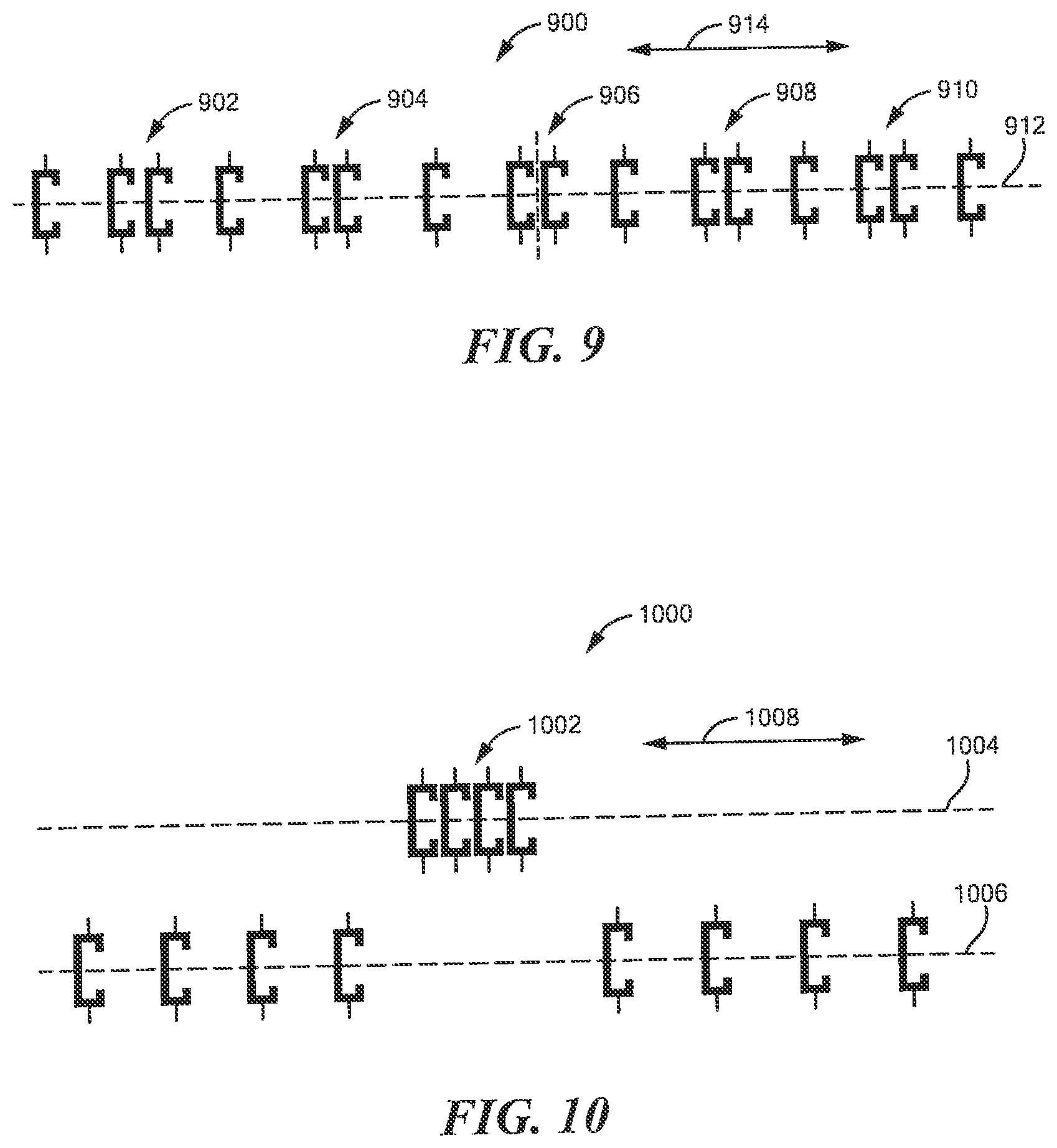
[0125] Referring now to FIG. 9, three or more magnetoresistance elements 900, here sixteen magnetoresistance elements, can be arranged with unequal spacing along a line 910, such that groups 902, 904, 906, 908, 910 of the magnetoresistance elements 900 are more closely spaced than other ones of the magnetoresistance elements 900. Features, e.g., gear teeth, of a target object can be stationary with respect to the three or more magnetoresistance elements 900, or can otherwise move and pass by the three or more magnetoresistance elements 900 in one or more directions indicated by an arrow 914.
[0126] It will be apparent that magnetoresistance elements more closely spaced provide a higher resolution of accuracy of the position of the feature (e.g., gear tooth) relative to the three or more magnetoresistance elements 900 if the feature is proximate to the more closely spaced magnetoresistance elements 902, 904, 906, 908, 910 or as the feature passes by the more closely spaced magnetoresistance elements 902, 904, 906, 908, 910.
[0127] Referring now to FIG. 10, three or more magnetoresistance elements 1000, here twelve magnetoresistance elements, can be arranged with unequal spacing along two lines 1004, 1006, such that a group 1002 of the magnetoresistance elements 1000 is more closely spaced than other ones of the magnetoresistance elements 1000. Features, e.g., gear teeth, of a target object can be stationary with respect to the three or more magnetoresistance elements 1000, or can otherwise move and pass by the three or more magnetoresistance elements 1000 in one or more directions indicated by an arrow 1008.
[0128] It will be apparent that magnetoresistance elements more closely spaced provide a higher resolution of accuracy of the position of the feature (e.g., gear tooth) relative to the three or more magnetoresistance elements 1000 if the feature is proximate to the more closely spaced magnetoresistance elements 1002 or as the feature passes by the more closely spaced magnetoresistance elements 1002.
[0129] It may be desirable to have the three or more magnetoresistance elements 1000 disposed along two or more line as shown. For example, the more closely spaced group 1002 may otherwise be close to some other magnetic field radiating structure, for example, a power trace upon a semiconductor substrate that holds the three or more magnetoresistance elements 1000. it this case, it may be desirable to move the more closely space group 1002 away from the power trace. There may be other reasons to have the three or more magnetoresistance elements 1000 arranged along two ore more lines.
[0130] Referring now to FIG. 11, a magnetic field sensor 1100 can be the same as or similar to the magnetic field sensors 100, 200 of FIGS. 1 and 2. A block 1104 is representative of the three or more magnetic field sensing elements 104a of FIGS. 1 and 2. A block 1108 is representative of the electronic circuit 114 of FIGS. 1 and 2.
[0131] The block 1104 representative of the three or more magnetic field sensing elements 104a elements is disposed on a surface 1102a of a substrate 1102. The magnetic field sensor 1100 can include a magnet 1110 disposed as shown behind the substrate 1102 such that a line perpendicular to the substrate 1102 intersects the magnet 1110. North and south poles of the magnet 1110 can be arranged as shown.
[0132] Unlike the magnetic field sensors shown above, here the substrate 1102 and the block 1104 representative of the three or more magnetic field sensing elements overlap a target object 1112. The ferromagnetic target object 1112 is shown here to be a ferromagnetic gear having gear teeth, e.g., 1112a, 1112b, 1112c. In another embodiment the magnet 1110 and target object 1112 can be replaced by a ring magnet or permanent magnet (hard ferromagnetic material) as described below in conjunction with FIGS. 13 and 14
[0133] The magnetic field sensor 1100 can be rotated in a direction 1122 to a next position one hundred eighty degrees apart from the position shown, with no degradation of performance. However, intermediate rotations may result in a degradation of performance or may not be possible due to contact with the ferromagnetic target object 1112.
[0134] The magnetic field sensor 1100 can be rotated in a direction of and arrow 1124 with a center of rotation anywhere along a line 1118, through approximately +/- twenty degrees, without substantial degradation of performance.
[0135] Referring now to FIG. 12, in which like elements of FIG. 11 are shown having like reference designations, a magnetic field sensor 1200 is like the magnetic field sensor 1100 of FIG. 11. However, unlike the magnetic field sensor 1100 of FIG. 11, the magnetic field sensor 1200 includes a magnet 1202 having north and south poles arranged as shown, perpendicular to the north and south pole arrangement of the magnet 1110 of FIG. 11.
[0136] Magnetic field sensors shown and described above are shown to sense a movement of ferromagnetic target object in the form of a gear or cam. However, FIGS. 13 and 14 described below show similar magnetic field sensors for sensing movement of a ring magnet. Comments made above about edge detectors, tooth detectors, and TPOS functions apply in the same way when sensing a ring magnet.
[0137] Referring now to FIG. 13, in which like elements of FIG. 11 are shown having like reference designations, a magnetic field sensor 1300 is like the magnetic field sensors described above. However, the magnetic field sensor 1300 has no internal magnet. Instead, the magnetic field sensor 1300 is responsive to passing magnetic domains (features) of a ring magnet 1312. N and S designations shown can be indicative of north and south poles associated with the ring magnet target. A S or N pole would exist on the other side of the page if magnetized perpendicular to the page. In other embodiments the N and S would be on the outer radial dimension toward the ring magnet while a complimentary S or N would exist on the inner radial side of the ring magnet.
[0138] In some embodiments, the magnetic domains of the ring magnet 1312 are magnetized parallel to the page. In some other embodiments, the magnetic domains of the ring magnet 1312 are magnetized perpendicular to the page.
[0139] Referring now to FIG. 14, in which like elements of FIGS. 11 and 13 are shown having like reference designations, a magnetic field sensor 1400 is like the magnetic field sensor of FIG. 13. The magnetic field sensor 1400 has no internal magnet. Instead, the magnetic field sensor 1500 is responsive to passing magnetic domains of the ring magnet 1312.
[0140] Unlike the magnetic field sensor 1300 of FIG. 13, the substrate 1302, in particular, the three or more magnetic field sensing elements 1104, overlaps the ring magnet 1312 such that a line perpendicular to the substrate 1102 intersects the ring magnet 1312. In other embodiments, more of the substrate 1102, or the entire substrate 1102, overlaps the ring magnet 1312.
[0141] Referring now to FIG. 15, a three or more magnetic field sensing elements, e.g., 1500, can be used as the three or more magnetic field sensing elements of the magnetic field sensors described above. However, unlike the three or more magnetic field sensing elements described above, the magnetic field sensing elements 1500 can be disposed in an arc 1502. In some embodiments, a radius of curvature of the arc 1502 can be the same as a radius of curvature of a ring magnet 1504 (or alternatively, a gear) to which the three or more magnetic field sensing elements 1500 are responsive. However, other radii of curvatures are also possible.
[0142] In some alternate arrangements represented, for example, by the magnetic field sensor 1400 of FIG. 14, the magnetic field sensing elements 1500 can be disposed over and overlap the ring magnet 1504.
[0143] In some embodiments, maximum response axes of the three or more magnetic field sensing elements 1700 are parallel to each other.
[0144] In some embodiments, maximum response axes of the three or more magnetic field sensing elements 1700 are not parallel to each other, but may be parallel to the arc 1502.
[0145] In some other embodiments, the three or more magnetic field sensing elements are arranged in a straight line, which is not parallel to a tangent to the ring magnet 1504, but which is at a diagonal to the ring magnet 1504.
[0146] While ferromagnetic target objects in the form of ferromagnetic gears and ferromagnetic ring magnets are described above, in other embodiments, any of the ferromagnetic target objects can be replaced by a non-ferromagnetic target object. In these embodiments, the non-ferromagnetic target object can be an electrically conductive target object in which eddy currents can be generated by rotation of the non-ferromagnetic conductive target object in the presence of a magnetic field, which may be supplied by a magnet the same as or similar to the magnets 110, 202 of FIGS. 1 and 2, respectively. In other embodiments, a coil or an electromagnet may provide the magnetic field. The above-described magnetic field sensing elements can be responsive to magnetic fields generated by the eddy currents in the non-ferromagnetic conductive target objects. Arrangements responsive to eddy currents are described, for example, in U.S. patent application Ser. No. 13/946,417, filed Jul. 19, 2013, and entitled "Methods And Apparatus For Magnetic Sensor Having An Integrated Coil Or Magnet To Detect A Non-Ferromagnetic Target," which supplication is assigned to the assignee of the present application, and which application is incorporated by reference herein in its entirety.
[0147] From the above, it will be understood that the target object sensed with magnetic field sensors described herein can be a ferromagnetic target object (e.g., a gear of a ring magnet) or a non-ferromagnetic conductive object (e.g., a gear).
[0148] Magnetic field sensors described above and below use a sensed position of the sensed target object to identify speed and/or direction of rotation. However, similar circuits and techniques can be used to a sense a speed and/or direction of linear movement (straight or curved one) of a different (straight or curved) target object having features (e.g., teeth or magnetic regions) arranged along a line (straight or curved).
[0149] Referring now to FIGS. 16 and 17, a pair of magnetoresistance elements 1700 comprised of first and second magnetoresistance elements 1602, 1604 can replace any of the three or more magnetoresistance elements or three or more magnetic field sensing elements described above. The first and second magnetoresistance elements 1602, 1604 can be coupled with first and second fixed value resistors 1708, 1710 and with a voltage generator 1702 forming a full bridge arrangement.
[0150] Referring now to FIG. 18, a magnetic field sensor 1800 can include a substrate 902 having a surface 902a. Three of more magnetic field sensing elements 1804 can be disposed upon the surface 1802a. The three or more magnetic field sensing elements can be similar to any of the above-described three or more magnetic field sensing elements.
[0151] An electronic circuit 1806 can be disposed upon the surface 1802. The electronic circuit 1806 can be similar to any of the above-described three or more magnetic field sensing elements, for example, the electronic circuits 300, 400, 500 of FIG. 3, 4, or 5.
[0152] The magnetic field sensor 1800 can be disposed proximate to, and can sense a position of and movement of, a circular (e.g., disk) magnet 1810 having a diameter and a thickness 1816. The circular magnet 1810 can have a first plurality of north poles and a first plurality of south poles, here two north poles and two south poles associated with a first surface 1810a of the circular magnet 1810. The circular magnet 1810 can also have a second plurality of north poles and a second plurality of south poles, here two north poles and two south poles, associated with a second surface 1810a of the circular magnet 1810. The first pluralities of poles can oppose the second plurality of poles across a thickness dimension 1816.
[0153] The circular magnet can be arranged to move, e.g., rotate, in a direction of an arrow. 1818.
[0154] Operation of the magnetic field sensor 1800 can be understood from discussion above in conjunction with other figures.
[0155] Referring now to FIG. 19, a magnetic field sensor 1900 can include a substrate 1902. The substrate can be like any of the substrates described above, and upon which any of the above magnetic field sensing elements and electronic circuits can be disposed.
[0156] Under the magnetic field sensor 1902 can be disposed a base plate 1904 of a lead frame also having a plurality of leads 1906a-1906N. The plurality of leads 1906a-1906N can be electrically coupled to the substrate with a plurality of wired bonds 1908a-1908N or the like, e.g., solder balls in a flip chip arrangement.
[0157] An integrated circuit package 1910, e.g., a plastic package, can surround the substrate 1902, baseplate 1904, wire bonds 1908a-1908N, and portions of the leads 1906a-1906N.
[0158] The integrated circuit 1900 can be a so-called SIP (single inline package) integrated circuit. Other package types are also possible, for example, and SOIC (small outline integrated circuit).
[0159] All references cited herein are hereby incorporated herein by reference in their entirety.
[0160] Having described preferred embodiments, which serve to illustrate various concepts, structures and techniques, which are the subject of this patent, it will now become apparent that other embodiments incorporating these concepts, structures and techniques may be used. Accordingly, it is submitted that the scope of the patent should not be limited to the described embodiments but rather should be limited only by the spirit and scope of the following claims.
[0161] Elements of embodiments described herein may be combined to form other embodiments not specifically set forth above. Various elements, which are described in the context of a single embodiment, may also be provided separately or in any suitable subcombination. Other embodiments not specifically described herein are also within the scope of the following claims.
* * * * *
D00000
D00001
D00002
D00003
D00004
D00005
D00006
D00007
D00008
D00009
D00010
D00011
D00012

D00013
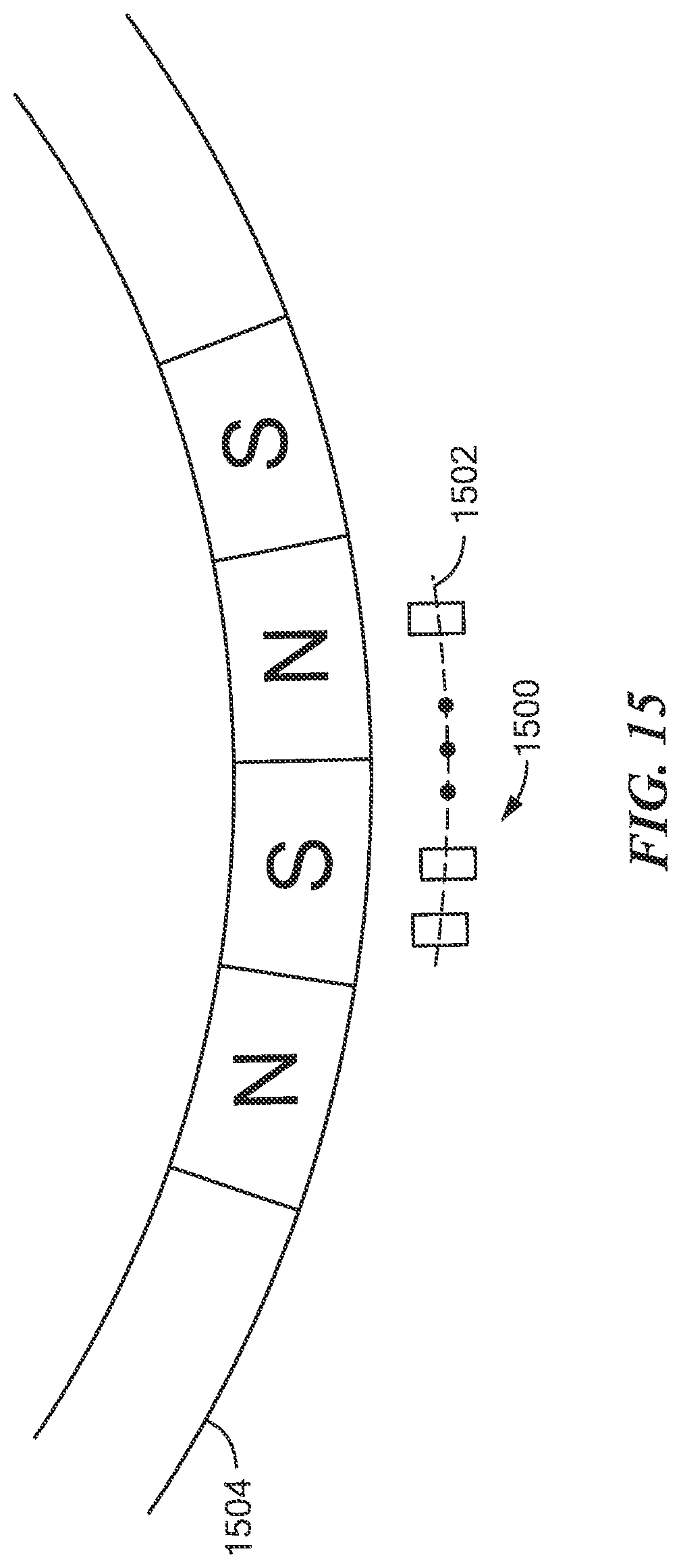
D00014

D00015

XML
uspto.report is an independent third-party trademark research tool that is not affiliated, endorsed, or sponsored by the United States Patent and Trademark Office (USPTO) or any other governmental organization. The information provided by uspto.report is based on publicly available data at the time of writing and is intended for informational purposes only.
While we strive to provide accurate and up-to-date information, we do not guarantee the accuracy, completeness, reliability, or suitability of the information displayed on this site. The use of this site is at your own risk. Any reliance you place on such information is therefore strictly at your own risk.
All official trademark data, including owner information, should be verified by visiting the official USPTO website at www.uspto.gov. This site is not intended to replace professional legal advice and should not be used as a substitute for consulting with a legal professional who is knowledgeable about trademark law.