Connection Structure For Motor Of Air Compressor
CHOU; Wen-San ; et al.
U.S. patent application number 16/706778 was filed with the patent office on 2020-07-02 for connection structure for motor of air compressor. The applicant listed for this patent is Wen-San Chou CHOU. Invention is credited to Cheng-Hsien Chou, Wen-San CHOU.
| Application Number | 20200208620 16/706778 |
| Document ID | / |
| Family ID | 68917620 |
| Filed Date | 2020-07-02 |

View All Diagrams
| United States Patent Application | 20200208620 |
| Kind Code | A1 |
| CHOU; Wen-San ; et al. | July 2, 2020 |
CONNECTION STRUCTURE FOR MOTOR OF AIR COMPRESSOR
Abstract
A connection structure for a motor of an air compressor contains: a base, a cylinder, a motor, and a transmission mechanism. The base includes a first positioning orifice and a second positioning orifice. The cylinder includes an air storage seat. A small-diameter gear is inserted through the first positioning orifice to fit on the motor, a bearing housing is accommodated in the first positioning orifice, and the motor includes a magnetic coil. The transmission mechanism actuates a piston to move in the cylinder reciprocately so as to compress air. The magnetic coil includes a first segment and a second segment, and the base includes two symmetrical elongated plates which respectively have two hooks. The base further includes two symmetrical arcuate retainers.
| Inventors: | CHOU; Wen-San; (Tainan City, TW) ; Chou; Cheng-Hsien; (Tainan City, TW) | ||||||||||
| Applicant: |
|
||||||||||
|---|---|---|---|---|---|---|---|---|---|---|---|
| Family ID: | 68917620 | ||||||||||
| Appl. No.: | 16/706778 | ||||||||||
| Filed: | December 8, 2019 |
| Current U.S. Class: | 1/1 |
| Current CPC Class: | F04B 41/00 20130101; F04B 35/04 20130101; F04B 53/16 20130101; F04B 39/121 20130101; F04B 35/00 20130101 |
| International Class: | F04B 35/00 20060101 F04B035/00; F04B 41/00 20060101 F04B041/00 |
Foreign Application Data
| Date | Code | Application Number |
|---|---|---|
| Dec 14, 2018 | TW | 107145367 |
Claims
1. A connection structure for a motor of an air compressor comprising: a base including multiple positioning orifices which are a first positioning orifice and a second positioning orifice; a cylinder connected on the base and including an air storage seat; a motor fixed on the base, a small-diameter gear being inserted through the first positioning orifice of the base to fit on a central shaft of the motor, a bearing housing of the motor being accommodated in the first positioning orifice, and the motor including a magnetic coil made of metal; and a transmission mechanism actuating a piston to move in the cylinder reciprocately so as to compress air; characterized in that: the magnetic coil of the motor includes a first segment and a second segment, the base includes two symmetrical elongated plates extending from a rear end of the base, and the two symmetrical elongated plates have two hooks extending therefrom respectively, the base further includes two symmetrical arcuate retainers extending from two inner walls of the two symmetrical elongated plates individually; the first segment of the magnetic coil of the motor abuts against two top faces of the two symmetrical arcuate retainers, and the two hooks of the two symmetrical elongated plates of the base are engaged with the magnetic coil so that the motor is fixed on the base.
2. The connection structure as claimed in claim 1, wherein the two hooks of the two symmetrical elongated plates of the base are engaged with the second segment of the magnetic coil so that the motor is fixed on the base.
3. The connection structure as claimed in claim 1, wherein a diameter of a top of the small-diameter gear is less than an outer diameter of the bearing housing, and the second positioning orifice accommodates a bearing.
4. The connection structure as claimed in claim 3, wherein the transmission mechanism includes a large-diameter gear having a counterweight block and meshing with the small-diameter gear, wherein the large-diameter gear is connected with the bearing via a connection rod.
5. The connection structure as claimed in claim 4, wherein the motor includes multiple through orifices defined around a front face thereof, and the base further includes multiple posts extending around the first positioning orifice and corresponding to the multiple through orifices respectively.
6. The connection structure as claimed in claim 1, wherein a diameter of a top of the small-diameter gear is more than an outer diameter of the bearing housing.
7. The connection structure as claimed in claim 1, wherein two symmetrical fixing orifices are defined between the first segment and the second segment of the magnetic coil so that the two hooks of the two symmetrical elongated plates of the base are engaged with the two symmetrical fixing orifices of the magnetic coil respectively, and the motor is fixed on the base.
Description
FIELD OF THE INVENTION
[0001] The present invention relates to a connection structure for a motor of an air compressor which is capable of fixing the motor on the base without using any screw(s).
BACKGROUND OF THE INVENTION
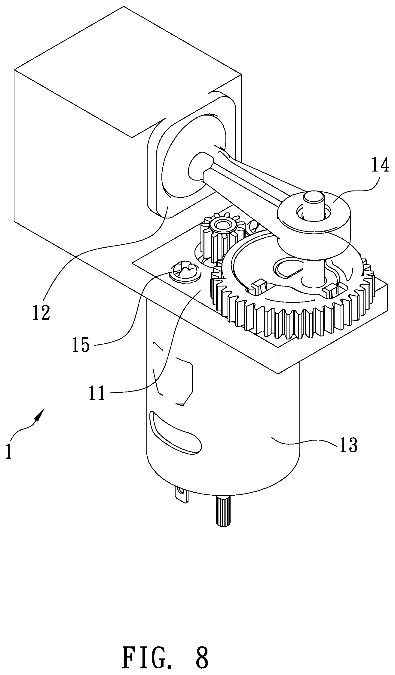
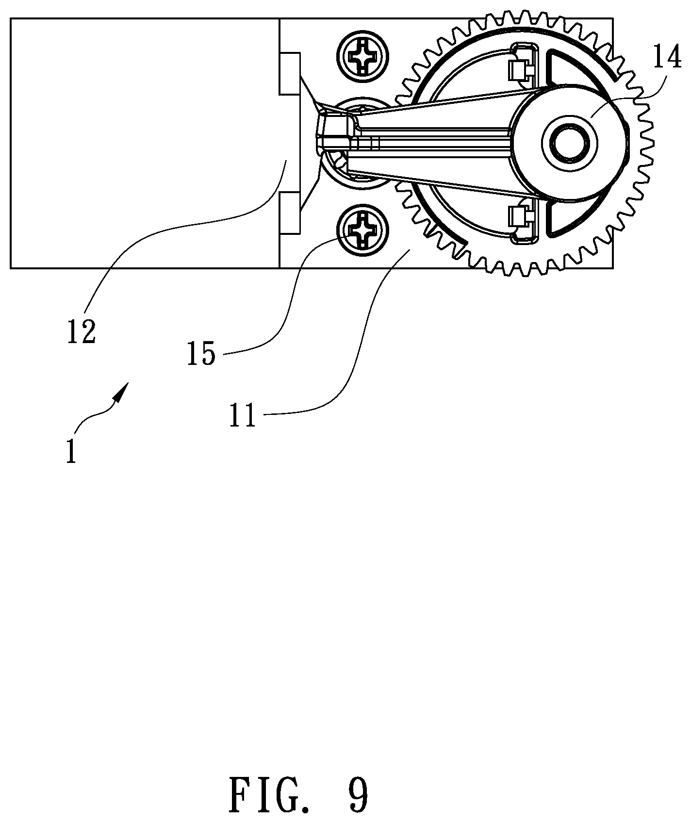
[0002] Referring to FIGS. 8 and 9, a conventional air compressor 1 is mounted on a vehicle and contains a base 11, a cylinder 12 connected on the base 11, a motor 13 fixed on the base 11, and a piston 14 driven by the motor 13 to move in the cylinder 12 reciprocately so as to draw, compress, and discharge air.
[0003] The motor 13 is fixed on the base 11 by using multiple screws 15. However, the multiple screws 15 are removed easily after a period of using time.
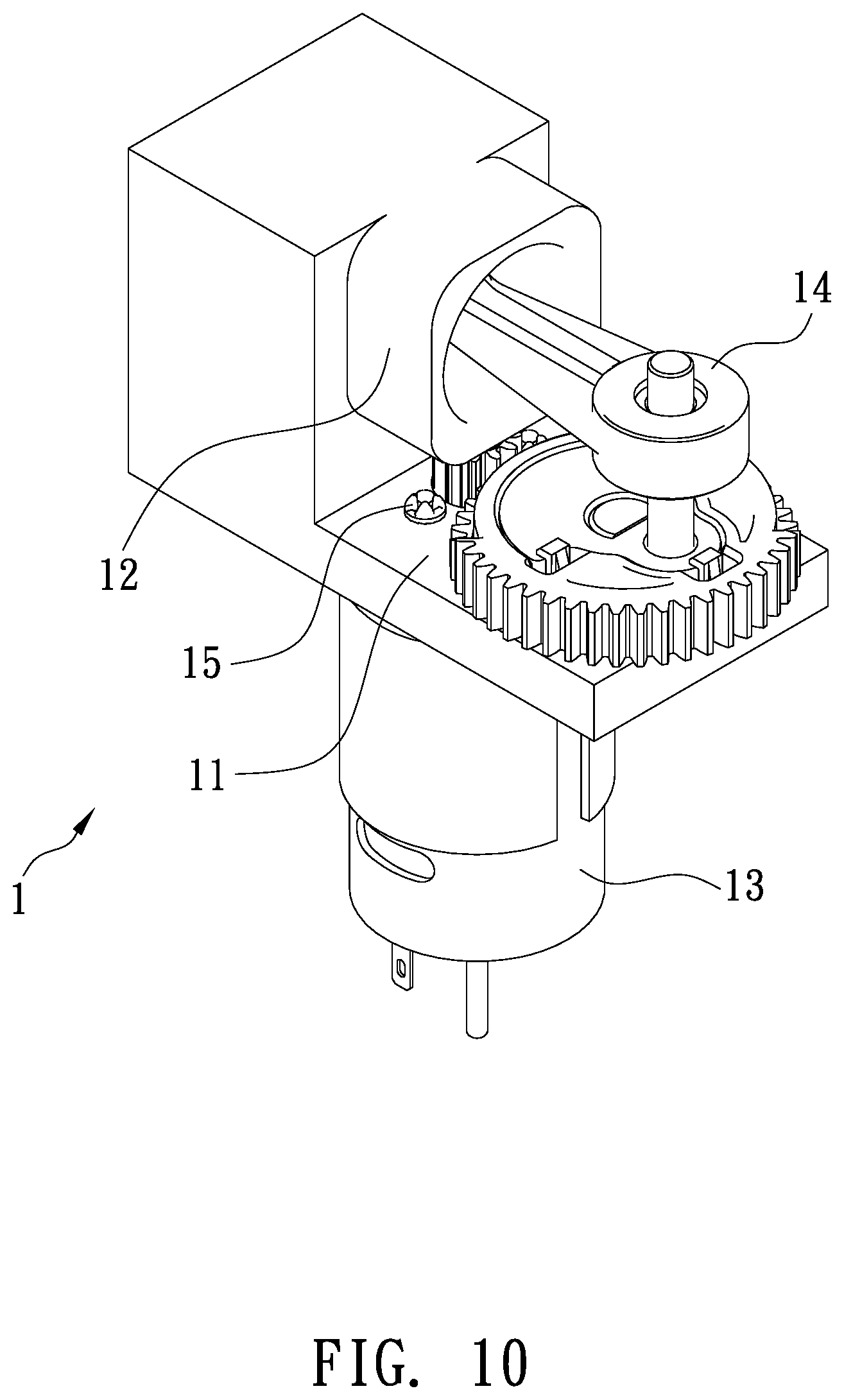
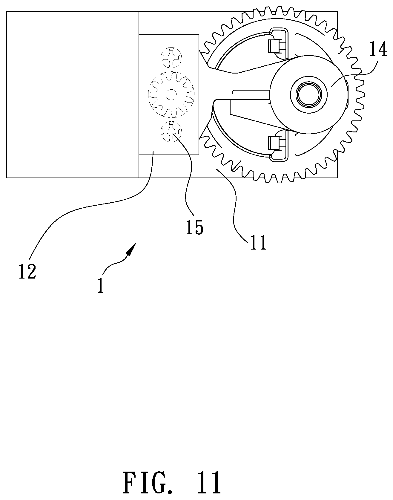
[0004] As illustrated in FIGS. 10 and 11, when a length of the cylinder 12 is too long, the motor 13 cannot be fixed on the base 11. In other words, the motor 13 cannot be fixed on the base 11 by using the multiple screws 15.
[0005] The present invention has arisen to mitigate and/or obviate the afore-described disadvantages.
SUMMARY OF THE INVENTION
[0006] The primary aspect of the present invention is to provide a connection structure for a motor of an air compressor which is capable of fixing the motor on the base without using any screw(s).
[0007] In operation, the multiple through orifices of the front face are engaged on the multiple posts of the base individually, and the bearing housing of the front face of the motor is received in the first positioning orifice of the base, wherein an outer wall of the motor is retained by the two symmetrical arcuate retainers of the base. In the meantime, the first segment of the magnetic coil of the motor abuts against two top faces of the two symmetrical arcuate retainers, and the two hooks of the two symmetrical elongated plates of the base are engaged with the second segment of the magnetic coil so that the motor is fixed on the base securely.
BRIEF DESCRIPTION OF THE DRAWINGS
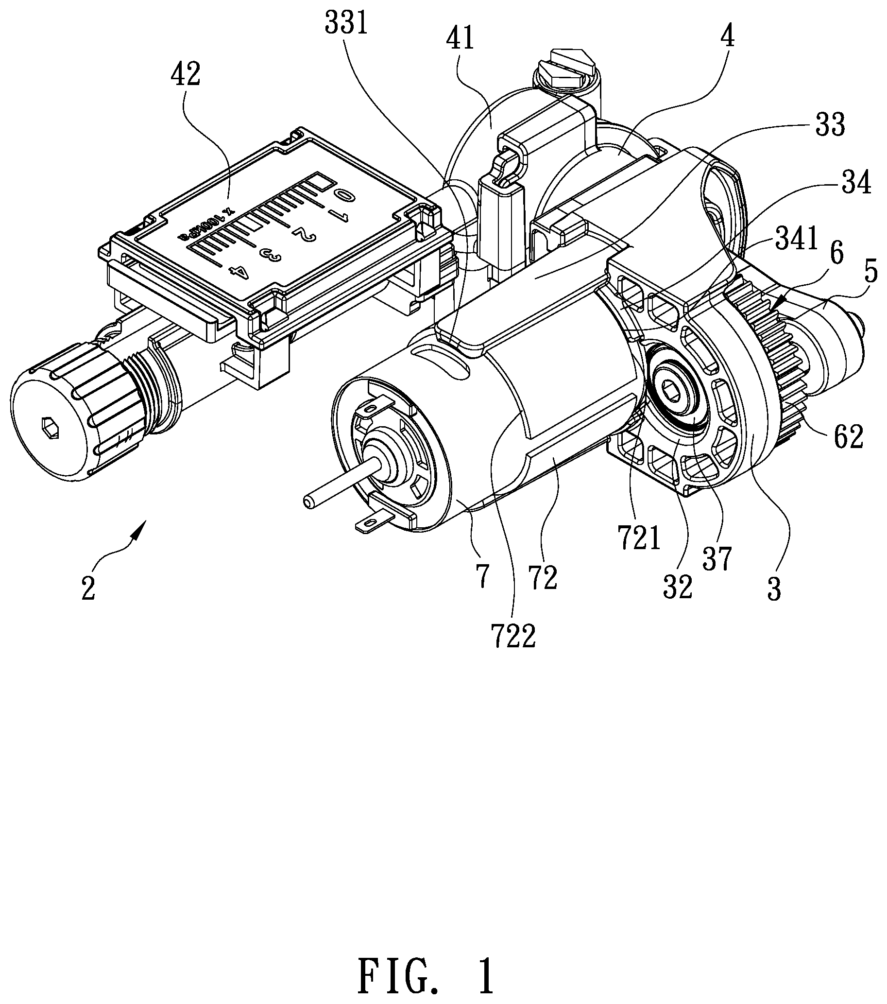
[0008] FIG. 1 is a perspective view showing the assembly of an air compressor according to a first embodiment of the present invention.
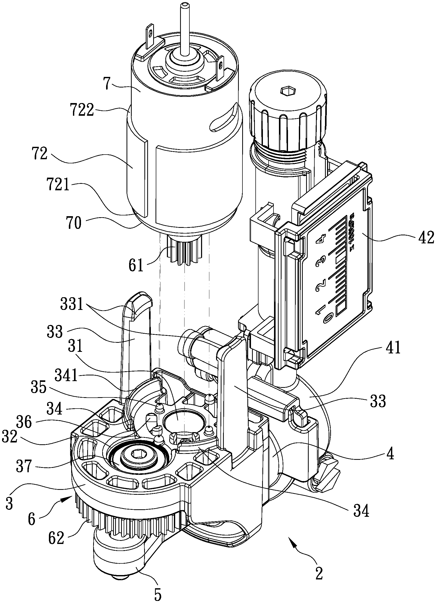
[0009] FIG. 2 is a perspective view showing the exploded components of the air compressor according to the first embodiment of the present invention.
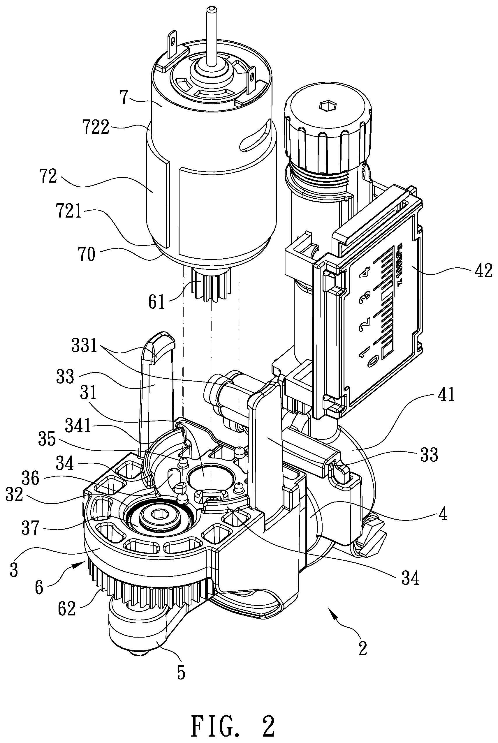
[0010] FIG. 3 is a perspective view showing the assembly of a part of the air compressor according to the first embodiment of the present invention.
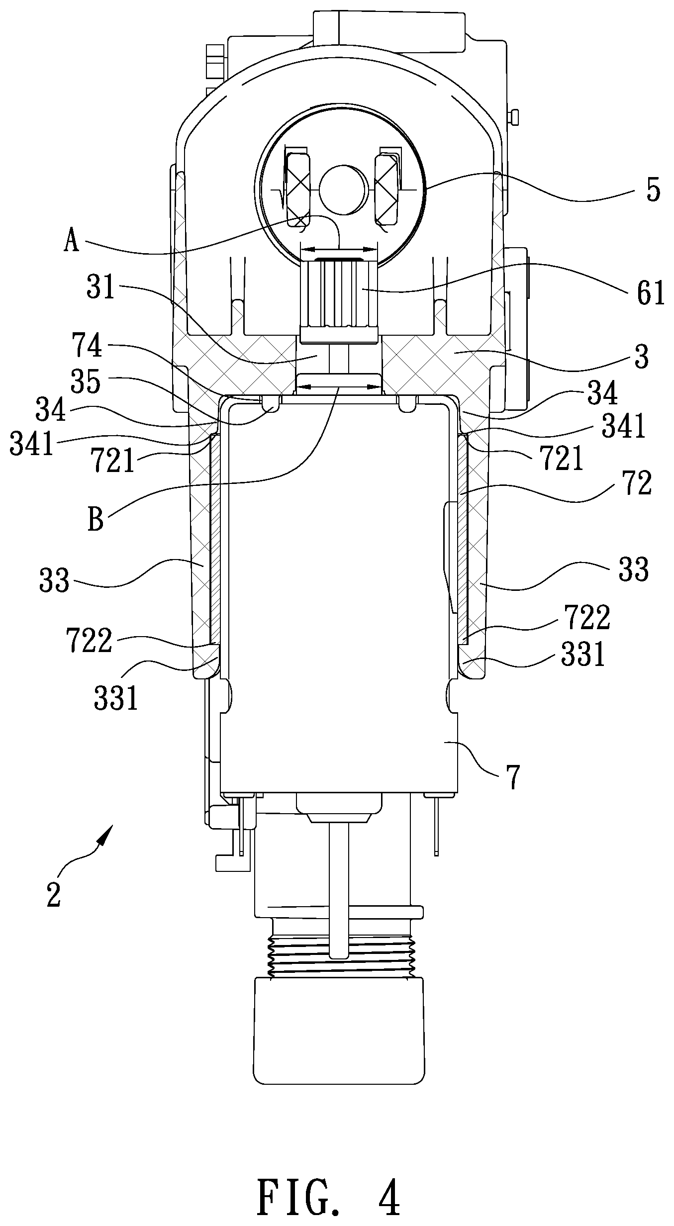
[0011] FIG. 4 is a cross sectional view showing the assembly of a part of the air compressor according to the first embodiment of the present invention.
[0012] FIG. 5 is another cross sectional view showing the assembly of a part of the air compressor according to the first embodiment of the present invention.
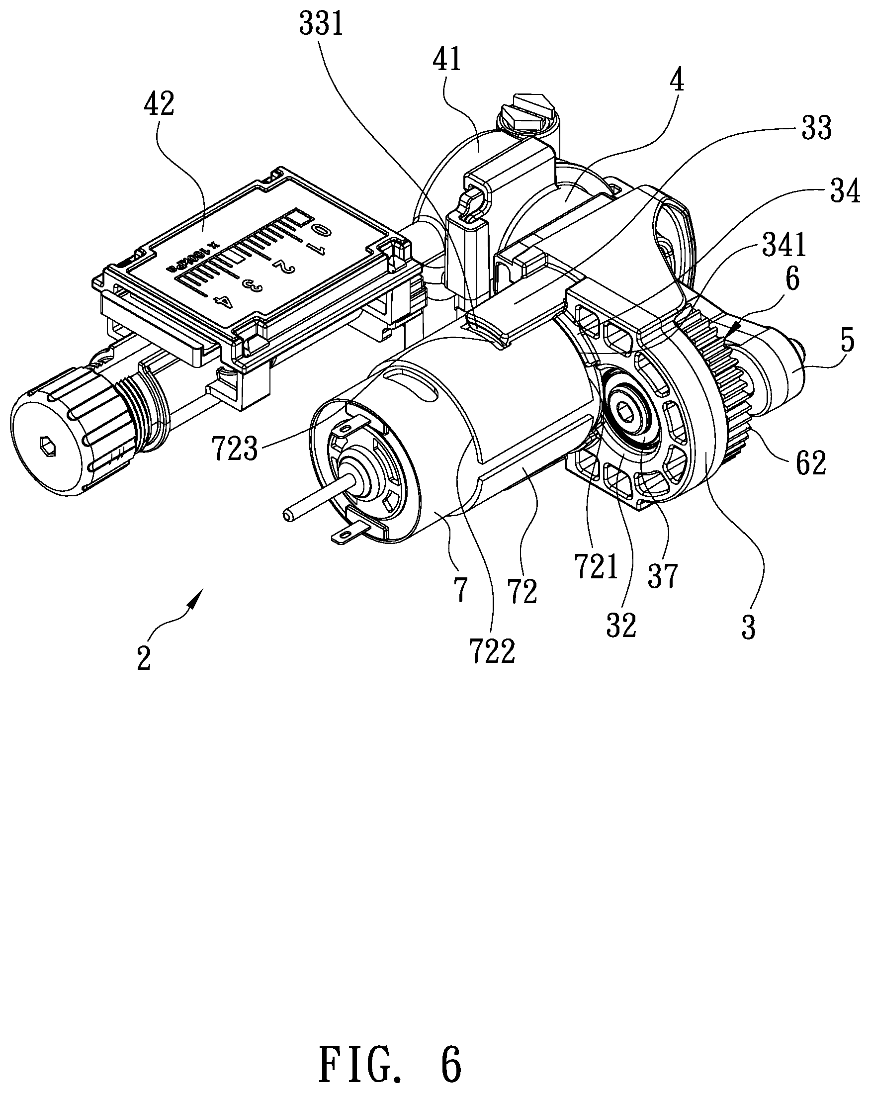
[0013] FIG. 6 is a perspective view showing the assembly of an air compressor according to a second embodiment of the present invention.
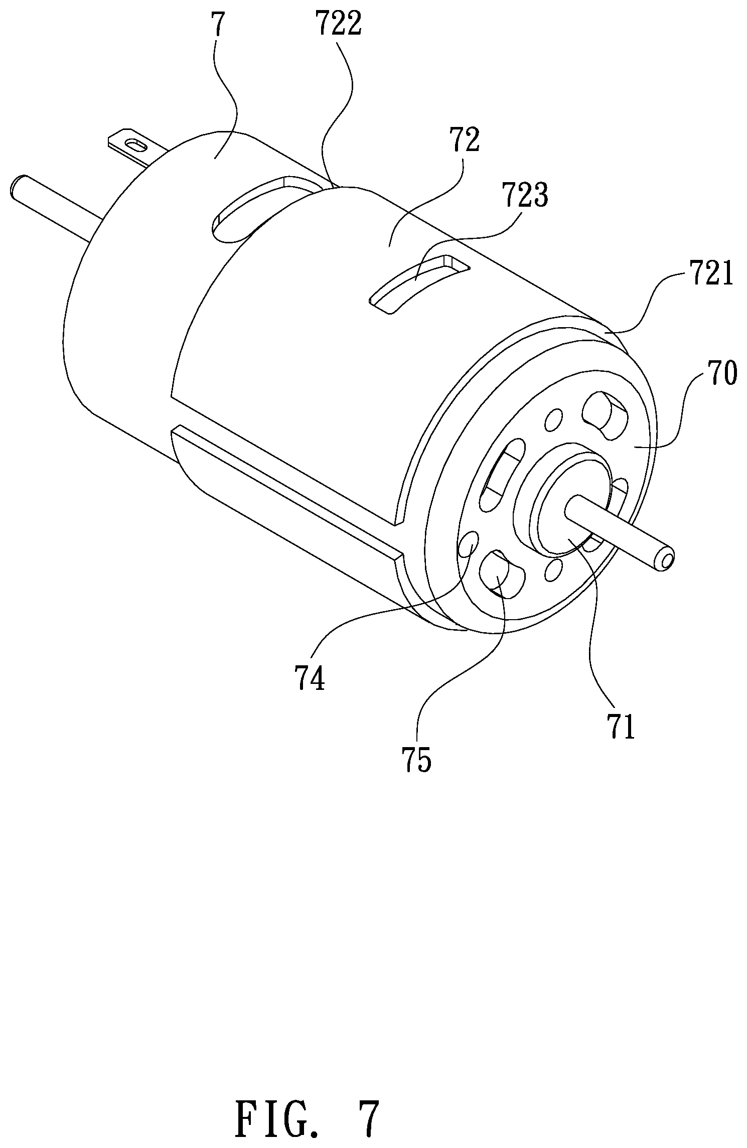
[0014] FIG. 7 is a perspective view showing the assembly of a part of the air compressor according to the second embodiment of the present invention.
[0015] FIG. 8 is a perspective view showing the assembly of a conventional air compressor.
[0016] FIG. 9 is a side plan view showing the assembly of the conventional air compressor.
[0017] FIG. 10 is another perspective view showing the assembly of the conventional air compressor.
[0018] FIG. 11 is another side plan view showing the assembly of the conventional air compressor.
DETAILED DESCRIPTION OF THE PREFERRED EMBODIMENTS
[0019] With reference to FIGS. 1-3, a connection structure for a motor 7 of an air compressor 2 according to a first embodiment of the present invention, the air compressor 2 comprises: a base 3, a cylinder 4 connected on the base 3, the motor 7 fixed on the base 3, and a piston 5 driven by the motor 7 to move in the cylinder 4 reciprocately.
[0020] The base 3 includes multiple positioning orifices which are a first positioning orifice 31 and a second positioning orifice 32, wherein a small-diameter gear 61 is inserted through the first positioning orifice 31 to fit on a central shaft of the motor 7, and a bearing housing 71 of the motor 7 is accommodated in the first positioning orifice 31, a diameter A of a top of the small-diameter gear 61 is less than an outer diameter B of the bearing housing 71, and the second positioning orifice 32 accommodates a bearing 37. The motor 7 includes a magnetic coil 72 made of metal and configured to guide magnetism so as to enhance operating efficiency of the motor 7.
[0021] The cylinder 4 is one-piece or is movably connected on the base 3, and the cylinder 4 includes an air storage seat 41, an air pipe connected with the air storage seat 41 and configured to delivery air, and a pressure gauge 42 coupled on the air storage seat 41.
[0022] The diameter A of the top of the small-diameter gear 61 is more than the outer diameter B of the bearing housing 71, as shown in FIG. 5.
[0023] A transmission mechanism 6 includes a large-diameter gear 62 having a counterweight block and meshing with the small-diameter gear 61, wherein the large-diameter gear 62 is connected with the bearing 37 via a connection rod (not shown), and the transmission mechanism 6 actuates the piston 5 to move in the cylinder 4 reciprocately so as to compress the air.
[0024] Referring to FIGS. 2-4, the magnetic coil 72 of the motor 7 includes a first segment 721 and a second segment 722, and the motor 7 includes multiple through orifices 74, 75 defined around a front face 70 thereof, wherein the small-diameter gear 61 is fitted on the front face 70 of the motor 7. The base 3 includes two symmetrical elongated plates 33 extending from a rear end of the base 3, and the two symmetrical elongated plates 33 have two hooks 331 extending therefrom respectively. The base 3 further includes two symmetrical arcuate retainers 34 extending from two inner walls of the two symmetrical elongated plates 33 individually, multiple posts 35, 36 (as shown in FIG. 2) extending around the first positioning orifice 31 and corresponding to the multiple through orifices 74, 75 respectively. When desiring to fix the motor 7 on the base 3, the multiple through orifices 74, 75 of the front face 70 are engaged on the multiple posts 35, 36 of the base 3 individually, and the bearing housing 71 of the front face 70 of the motor 7 is received in the first positioning orifice 31 of the base 3, wherein an outer wall of the motor 7 is retained by the two symmetrical arcuate retainers 34 of the base 3. In the meantime, the first segment 721 of the magnetic coil 72 of the motor 7 abuts against two top faces 341 of the two symmetrical arcuate retainers 34, and the two hooks 331 of the two symmetrical elongated plates 33 of the base 3 are engaged with the second segment 722 of the magnetic coil 72 so that the motor 7 is fixed on the base 3 securely.
[0025] In a second embodiment, as illustrated in FIGS. 6 and 7, two symmetrical fixing orifices 723 are defined between the first segment 721 and the second segment 722 of the magnetic coil 72 so that the two hooks 331 of the two symmetrical elongated plates 33 of the base 3 are engaged with the two symmetrical fixing orifices 723 of the magnetic coil 72 respectively, and the motor 7 is fixed on the base 3 securely.
[0026] Thereby, the multiple through orifices 74, 75 of the motor 7 are engaged on the multiple posts 35, 36 of the base 3 individually, and the bearing housing 71 of the front face 70 of the motor 7 is received in the first positioning orifice 31 of the base 3, wherein the outer wall of the motor 7 is retained by the two symmetrical arcuate retainers 34 of the base 3. In the meantime, the first segment 721 of the magnetic coil 72 of the motor 7 abuts against two top faces 341 of the two symmetrical arcuate retainers 34, and the two hooks 331 of the two symmetrical elongated plates 33 of the base 3 are engaged with the magnetic coil 72 so that the motor 7 is fixed on the base 3 securely.
[0027] While the preferred embodiments of the invention have been set forth for the purpose of disclosure, modifications of the disclosed embodiments of the invention and other embodiments thereof may occur to those skilled in the art. Accordingly, the appended claims are intended to cover all embodiments which do not depart from the spirit and scope of the invention.
* * * * *
D00000
D00001
D00002
D00003
D00004
D00005
D00006
D00007
D00008
D00009
D00010
D00011
XML
uspto.report is an independent third-party trademark research tool that is not affiliated, endorsed, or sponsored by the United States Patent and Trademark Office (USPTO) or any other governmental organization. The information provided by uspto.report is based on publicly available data at the time of writing and is intended for informational purposes only.
While we strive to provide accurate and up-to-date information, we do not guarantee the accuracy, completeness, reliability, or suitability of the information displayed on this site. The use of this site is at your own risk. Any reliance you place on such information is therefore strictly at your own risk.
All official trademark data, including owner information, should be verified by visiting the official USPTO website at www.uspto.gov. This site is not intended to replace professional legal advice and should not be used as a substitute for consulting with a legal professional who is knowledgeable about trademark law.