Method Of Preheating And Controlling The Temperature Of Fuel Injected Into A Combustion Engine
Lepsch; Fernando ; et al.
U.S. patent application number 16/690513 was filed with the patent office on 2020-07-02 for method of preheating and controlling the temperature of fuel injected into a combustion engine. The applicant listed for this patent is ROBERT BOSCH LIMITADA. Invention is credited to Marcello Francisco Brunocilla, Fernando de Oliveira, JR., Fernando Lepsch.
| Application Number | 20200208595 16/690513 |
| Document ID | / |
| Family ID | 71079741 |
| Filed Date | 2020-07-02 |


| United States Patent Application | 20200208595 |
| Kind Code | A1 |
| Lepsch; Fernando ; et al. | July 2, 2020 |
METHOD OF PREHEATING AND CONTROLLING THE TEMPERATURE OF FUEL INJECTED INTO A COMBUSTION ENGINE
Abstract
Method of preheating and controlling the temperature of fuel injected into a combustion engine to enable a reduction in the amount of fuel injected into engines which may be powered both by pure gasoline and by ethanol or any biofuel mixture, where the engine is located in environments with low temperatures and extremely cold temperatures.
| Inventors: | Lepsch; Fernando; (Campinas - SP, BR) ; de Oliveira, JR.; Fernando; (Campinas - SP, BR) ; Brunocilla; Marcello Francisco; (Indaiatuba - SP, BR) | ||||||||||
| Applicant: |
|
||||||||||
|---|---|---|---|---|---|---|---|---|---|---|---|
| Family ID: | 71079741 | ||||||||||
| Appl. No.: | 16/690513 | ||||||||||
| Filed: | November 21, 2019 |
| Current U.S. Class: | 1/1 |
| Current CPC Class: | F02D 41/062 20130101; F02D 2200/0606 20130101; F02M 53/02 20130101 |
| International Class: | F02M 53/02 20060101 F02M053/02; F02D 41/06 20060101 F02D041/06 |
Foreign Application Data
| Date | Code | Application Number |
|---|---|---|
| Dec 26, 2018 | BR | 102018077092-6 |
Claims
1. A method of preheating and controlling the temperature of fuel injected into a combustion engine, comprising: an electronic fuel injection control unit in the engine, at least one fuel-heating device (3) positioned in contact with the fuel; at least one fuel-heating control unit (6) connected by means of at least one data connection to the electronic injection control unit (9), and electrically connected to at least one fuel-heater (3), where the fuel-heating control unit (6) controls the operation of at least one fuel heater (3); characterized by comprising the stages of: turning on the heating system; measuring an initial temperature of the fuel (t.sub.inc) upstream of the heater (3); measuring an ambient temperature (t.sub.amb); reading a target temperature of the pre-heated fuel (t.sub.pre) downstream of the heater; comparing the initial temperature of the fuel (t.sub.inc) upstream of the heater (3) and the target temperature (t.sub.pre) of the pre-heated fuel; calculating a preheating power (p.sub.pre) necessary to be applied in the heater (3); applying a power (p.sub.pre) calculated in the heater (3) controlled by the heating control unit; comparing the temperature of the fuel (t.sub.c) downstream of the heater with the target temperature (t.sub.pre) of the pre-heated fuel; enabling the startup of the engine (8) when the fuel temperature condition (t.sub.c) is greater than or equal to the target temperature of the preheated fuel (t.sub.pre); measuring a temperature of the fuel (t.sub.c) downstream of the heater (3); reading a target temperature of the fuel (t.sub.a) downstream of the previously cited heater (3); comparing the temperature of the fuel (t.sub.c) downstream of the heater with the target temperature (t.sub.a) downstream of the heater; calculating a power (p.sub.aq) necessary to be used in the heater (3); applying a power (P.sub.aq) calculated in the heater (3) controlled by the heating control unit (6); comparing the temperature of the fuel (T.sub.c) downstream of the heater with the target temperature of the fuel (T.sub.a).
2. The method of preheating and controlling the temperature of fuel injected into a combustion engine in accordance with claim 1, characterized by the interruption of the application of power (P.sub.aq) in the heater when the temperature of the fuel (T.sub.c) downstream of the heater (3) is greater than the target temperature of the fuel (T.sub.a).
3. The method of preheating and controlling the temperature of fuel injected into a combustion engine in accordance with claim 1, characterized by the interruption of the application of power (P.sub.aq) in the heater when the temperature of the fuel (T.sub.c) downstream of the heater (3) is equal to the target temperature of the fuel (T.sub.a).
4. The method of preheating and controlling the temperature of fuel injected into a combustion engine in accordance with claim 1, characterized by the fact that the temperature of the fuel (T.sub.c) is processed by the electronic engine control unit (9).
5. The method of preheating and controlling the temperature of fuel injected into a combustion engine in accordance with claim 1, characterized by the fact that the temperature of the fuel (T.sub.c) is processed via the heating control unit (6).
6. The method of preheating and controlling the temperature of fuel injected into a combustion engine in accordance with claim 1, characterized by the fact that it comprises an anticipated power storage stage for the heating of the fuel (P.sub.aq).
Description
BACKGROUND OF THE INVENTION
[0001] This invention concerns a method for preheating and controlling the temperature of fuel injected into a combustion engine that allows for a reduction in the amount of fuel injected into engines that may be powered both by pure gasoline and by ethanol or any bi-fuel mixture, located in environments with low temperatures and extremely cold temperatures, including below 0.degree. C.
[0002] In recent years, problems concerning the amounts of pollutants emitted (HC, CO, CO.sub.2 and particulates), principally by car engines, have been a major problem for large cities. As a result, new technologies have been developed to help in the reduction of pollutants emitted by internal combustion engines.
[0003] When we talk about engines that use the Otto cycle (engines that can be powered both by pure gasoline and ethanol or any bi-fuel mixture), both those that use Port Fuel Injection (PFI) and those that operate with Direct Injection (DI) emit particulates above the permitted limits. As a result, the use of a particle filter for gasoline engines (whose acronym is GPF, from the English Gasoline Particulate Filter) has been recommended to comply with new particulate emissions laws that have come into force.
[0004] However, even with the use of GPF, engines can still generate particulates above the limits determined by the official health agencies, since emissions of pollutants also depend on drivers' conduct, regarding how they drive and the adequate maintenance of their vehicles.
[0005] In addition to this, the condensation of fuel in cold areas of the engine can result in incomplete combustion, generating hydrocarbons and carbon monoxide (HC and CO).
[0006] Some solutions to this type of problem are already known, such as the solution described in patent document PI 0902488-3. This document describes a fuel heater arranged in the internal combustion engine. In addition to this, this document describes a device for determining fuel temperature and pressure, adjusting the target fuel temperature in accordance with the fuel pressure detected by a pressure sensor and a fuel temperature control device that controls the fuel heater, in order to adjust the temperature detected by a sensor to the target temperature of the fuel.
[0007] However, in the invention described in this patent document it is mandatory to use a fuel pressure sensor, causing the target temperature to be adjusted according to the fuel pressure measured. Moreover, it is not necessary to know the upstream temperature of the heater, which makes the calculation of the power necessary to heat the fuel less accurate, thus not satisfactorily achieving the reduction in pollutants.
[0008] Another technique related to this problem is described in patent document WO2017/221036. Generally speaking, this invention describes a vehicle that reduced fuel injection volumes due to the heating of fuel. In more detail, this document describes a vehicle with an internal combustion engine equipped with at least one heater to heat the fuel before it is delivered to the cylinder by the fuel injector; a fuel pump connected to the heater to provide fuel to the heater, and a controller of the engine torque and the fuel pressure generated by the pump, where the engine controller uses a heated fuel behavior model of the engine when the fuel is being heated by the heater, to control the amount of fuel supplied by the fuel injector, in order to reduce the amount of fuel injection for a given engine torque in relation to the unheated fuel; and to cause greater fuel pressure to be generated by the fuel pump in relation to the unheated fuel.
[0009] The technique revealed in patent document WO2017/221036 describes a system where controlling the amount of fuel injected into the engine and increasing fuel pressure is achieved based on a heated fuel model in relation to the unheated model. In other words, it employs a highly complicated logic, which uses two injection control models.
SUMMARY OF THE INVENTION
[0010] So, the present invention proposes to solve the problems of the state of the art in a much more simplified and efficient manner with applications in environments with extremely cold temperatures, including below 0.degree. C.
[0011] In order to solve the technical problem presented and overcome the disadvantages of the documents described in the state of the art, and allow for a reduction in pollutants when the engine is located in environments with extremely low temperatures, this invention seeks to provide a simple and efficient method of preheating and controlling the temperature of the fuel injected into combustion engines, which comprises:
[0012] an electronic fuel injection control unit in the engine,
[0013] at least one fuel-heating device arranged in contact with the fuel,
[0014] at least one fuel-heating control unit 6 connected by means of at least one data connection to the electronic injection control unit, and electrically connected to at least one fuel-heater, where the fuel-heating control unit controls the operation of at least one fuel heater;
[0015] where the said method, and object of the present invention, comprises the steps of:
[0016] turning on the heating system;
[0017] measuring an initial temperature of the upstream fuel t.sub.inc of the heater 3;
[0018] measuring an ambient temperature t.sub.amb;
[0019] reading a target temperature of the pre-heated fuel t.sub.pre downstream of the heater;
[0020] comparing the initial temperature of the fuel t.sub.inc upstream of the heater and the target temperature t.sub.pre of the pre-heated fuel;
[0021] calculating a preheating power p.sub.pre necessary to be applied in the heater 3;
[0022] applying a preheating power p.sub.pre calculated in the heater 3 controlled by the heating control unit;
[0023] comparing the temperature of the fuel t.sub.c downstream of the heater with the target temperature t.sub.pre of the pre-heated fuel;
[0024] enabling the startup of the engine 8 when the fuel temperature condition t.sub.c is greater than or equal to the target temperature of the preheated fuel t.sub.pre;
[0025] measuring a temperature of the fuel t.sub.c downstream of the heater 3;
[0026] reading a target temperature of the fuel t.sub.a downstream of the previously cited heater 3;
[0027] comparing the temperature of the fuel t.sub.c downstream of the heater with the target temperature t.sub.a downstream of the heater;
[0028] calculating a power p.sub.aq necessary to be used in the heater 3;
[0029] applying a power P.sub.aq calculated in the heater 3 controlled by the heating control unit 6.
BRIEF DESCRIPTION OF THE DRAWINGS
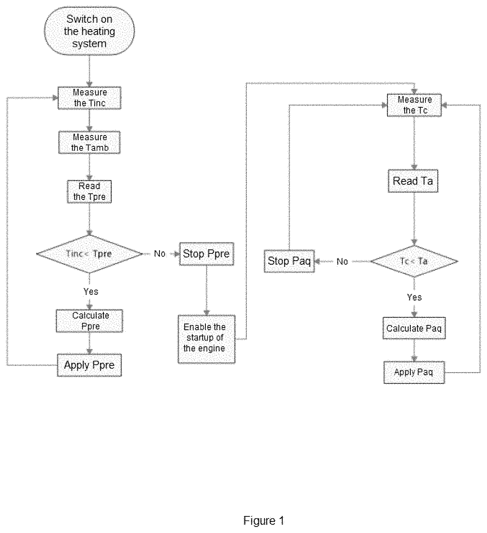
[0030] FIG. 1--Diagram of the method of preheating and controlling the temperature of the injected fuel.
[0031] FIG. 2--Schematic of a first embodiment of the heating system.
[0032] FIG. 3--Schematic of a second embodiment of the heating system.
[0033] FIG. 4--Details of a configuration of the heating system with a master temperature sensor.
[0034] FIG. 5--Details of a second configuration of the heating system with individual temperature sensors.
DETAILED DESCRIPTION
[0035] The fuel heating and heating management system is responsible for heating the fuel that will be injected into the engine up to a predetermined temperature. The heating of the fuel is intended to improve the atomization of the spray of the injected fuel, reducing its drop size, which results in improved preparation of the air-fuel mixture, leading to a more homogeneous mixture, which will result in a decrease in the amount of fuel injected, thus decreasing the quantity of gases and particulates emitted.
[0036] As can be seen from FIG. 2, the said fuel heating system is equipped with:
[0037] at least one electronic command unit 9;
[0038] at least one heating control unit 6;
[0039] at least one fuel heater 3, which can be inserted inside or outside a fuel rail 1;
[0040] at least one fuel injector 2.
[0041] Where the rail 1 and injectors 2 are connected by hoses to a fuel pump 7 (represented in FIGS. 1 and 2 integrated into the fuel tank) that pressurizes the fuel line 11, and where there may or may not be downstream and upstream temperature sensors of the fuel heater.
[0042] As can be seen in FIG. 1, the operation of the heating system occurs from the moment that the preheating of the fuel begins. Preheating is critical for locations where the ambient temperature is extremely low, and can reach several degrees below 0.degree. C. The management of the system is intended to preheat the fuel before the engine starts from an initial fuel temperature t.sub.inc to an injected fuel temperature T.sub.c, and to keep the fuel temperature T.sub.c constant, so that it is greater than or equal to the target temperature T.sub.a. For this purpose, the system determines the amount of energy that must be supplied to the fuel, based on the fuel inlet temperature on the rail 1, the fuel flow rate and the fuel type.
[0043] Thus, the present invention describes a method for controlling the temperature of fuel injected into a combustion engine, which comprises:
[0044] an electronic fuel injection control unit in the engine;
[0045] at least one fuel-heating device 3 arranged in contact with the fuel;
[0046] at least one fuel-heating control unit 6 connected by means of at least one data connection to the electronic injection control unit, and electrically connected to at least one fuel-heater, where the fuel-heating control unit controls the operation of at least one fuel heater;
[0047] where the said method, and object of the present invention, comprises the steps of:
[0048] turning on the heating system;
[0049] measuring an initial temperature of the fuel t.sub.inc upstream of the heater 3;
[0050] measuring an ambient temperature t.sub.amb;
[0051] reading a target temperature of the pre-heated fuel t.sub.pre downstream of the heater;
[0052] comparing the initial temperature of the fuel t.sub.inc upstream of the heater with the target temperature t.sub.pre of the pre-heated fuel;
[0053] calculating a preheating power p.sub.pre necessary to be applied in the heater 3;
[0054] applying a preheating power p.sub.pre calculated in the heater 3 controlled by the heating control unit;
[0055] comparing the temperature of the fuel t.sub.c downstream of the heater with the target temperature t.sub.pre of the pre-heated fuel;
[0056] enabling the startup of the engine 8 when the fuel temperature condition t.sub.c is greater than or equal to the target temperature t.sub.pre of the preheated fuel;
[0057] measuring a temperature of the fuel t.sub.c downstream of the heater 3;
[0058] reading a target temperature of the fuel t.sub.a downstream of the previously cited heater 3;
[0059] comparing the temperature of the fuel t.sub.c downstream of the heater with the target temperature t.sub.a downstream of the heater;
[0060] calculating a power p.sub.aq necessary to be used in the heater 3;
[0061] applying a power P.sub.aq calculated in the heater 3 controlled by the heating control unit 6.
[0062] The ambient temperature can be measured by means of an ambient temperature sensor, or it can also be obtained by measuring the temperature of the air or the engine water. Another important factor is that the startup of the engine is not enabled while the temperature of the fuel t.sub.c is not greater than or equal to the preheating target temperature T.sub.pre. When this temperature condition T.sub.c is met, then the startup of the engine is enabled.
[0063] The heating system, equipped with the heater 3 and heating control unit 6, does not heat the fuel when the temperature upstream of the heater is equal to or greater than the target temperature T.sub.a. For example, during the operation of the engine 8, after a long period of use, it heats up and begins to heat the components around it. The temperature of the engine 8 can be such that it causes the inlet fuel to heat up to the target temperature T.sub.a without the need to start the fuel heater 3. In this case, the heater 3 is switched off to save energy, as the heating of the fuel by the heaters 3 is no longer needed.
[0064] As for the preheating target temperature T.sub.pre and the target temperature T.sub.a of the heating of the fuel, they may coincide, there being no need for them to be equal.
[0065] A fundamental aspect of this invention, in order for the reduction in emissions of pollutants to be fully achieved, is the temperature of the injected fuel T.sub.c. The temperature of the fuel T.sub.c downstream of the heater 3 must be known. To know the temperature of the injected fuel T.sub.c, a temperature sensor 4 can be placed at the outlet of the fuel rail 1 or in the injector 2. A sensor 4 can be positioned at each outlet (for each injector 2) as shown in FIG. 5, or an outlet can be used as a master (this will be the reference of the fuel temperature T.sub.c for all the injectors, regardless of the number of cylinders), as shown in FIG. 4. When using a sensor 4 for each injector 2, the power applied P.sub.aq to all the heaters 3 will be such that the target temperature T.sub.a is obtained equally downstream of each heater 3, regardless of a possible imbalance between the resistances of each heater 3.
[0066] In another embodiment of the system, no temperature sensor is used in the heating system. In this case, the temperature of the injected fuel T.sub.c is calculated using a temperature model inserted in the vehicle's electronic control unit 9 or in the control unit of the heaters 6. This model collects other information from the vehicle to discover what temperature the fuel was heated to.
[0067] In addition to this, the temperature of the fuel at the entrance to the rail upstream of the heater T.sub.cm is another important aspect of the present invention. The temperature of the fuel upstream of the heater T.sub.cm must be known. To determine the initial temperature of the fuel to be heated, you can place a fuel temperature sensor anywhere on the fuel line, between the fuel tank 8 and the heater 3. However, the closer it is to the heater 3, the more accurate the temperature measurement will be.
[0068] In an alternative embodiment of the system, no temperature sensor is used to measure the temperature upstream of the heater 3. In this case, the temperature of the fuel T.sub.cm upstream of the heater 3 is calculated based on other temperature sensors available in the engine, such as the cooling water temperature sensor of the engine (not shown in the figures), or the inlet air temperature sensor of the engine (also not shown), or the oil temperature sensor of the engine (where available).
[0069] Some variables that influence the proposed method are already known, and are calculated using the electronic control unit of the vehicle 9, such as the fuel flow rate through the rail 1 and the type of fuel.
[0070] In some dynamic conditions, both a sudden acceleration and a severe deceleration can be requested by the driver. In these situations, there is a great variation in the acceleration pedal, detected by the engine management system. So, the engine management system can predict whether the engine will require more or less fuel mass. Thus, it anticipates the injection of a greater or lesser volume of fuel to enable the acceleration or deceleration based on a predetermined fuel volume for that engine speed transition. So, using this same concept, the fuel management system can anticipate the heating of the fuel. In this case, a pre-targeting, or early storage, of power P.sub.aq for fuel heating can be determined in the electronic control unit 9, anticipating the fuel heating, so that the temperature of the fuel T.sub.c remains at the target temperature T.sub.a, even with a sharp variation in the fuel flow rate.
[0071] Thus, during abrupt acceleration changes, there are no changes in the temperature of the fuel T.sub.c, since the heating control system has already heated the fuel previously. In addition to this, the heating of the fuel in these dynamic maneuvers also produces a reduction in pollutants, as such maneuvers serve to increase the total level of emissions emitted by the vehicle.
* * * * *
D00000
D00001
D00002
D00003
XML
uspto.report is an independent third-party trademark research tool that is not affiliated, endorsed, or sponsored by the United States Patent and Trademark Office (USPTO) or any other governmental organization. The information provided by uspto.report is based on publicly available data at the time of writing and is intended for informational purposes only.
While we strive to provide accurate and up-to-date information, we do not guarantee the accuracy, completeness, reliability, or suitability of the information displayed on this site. The use of this site is at your own risk. Any reliance you place on such information is therefore strictly at your own risk.
All official trademark data, including owner information, should be verified by visiting the official USPTO website at www.uspto.gov. This site is not intended to replace professional legal advice and should not be used as a substitute for consulting with a legal professional who is knowledgeable about trademark law.