Steerable Downhole Drilling Tool
ZHAN; Sheng
U.S. patent application number 16/237131 was filed with the patent office on 2020-07-02 for steerable downhole drilling tool. The applicant listed for this patent is China Petroleum & Chemical Corporation Sinopec Tech Houston, LLC.. Invention is credited to Sheng ZHAN.
| Application Number | 20200208472 16/237131 |
| Document ID | / |
| Family ID | 71121699 |
| Filed Date | 2020-07-02 |
| United States Patent Application | 20200208472 |
| Kind Code | A1 |
| ZHAN; Sheng | July 2, 2020 |
STEERABLE DOWNHOLE DRILLING TOOL
Abstract
A drill bit has a bit body that has a cutting structure mounted on a base section. The cutting structure has a plurality of roller cones, a plurality of fixed blades, or both. The base section has a plurality of pad that are extendable from a circumference of the base section. The base section is connected to a threaded pin connectable with a lower end of a drill string.
| Inventors: | ZHAN; Sheng; (Houston, TX) | ||||||||||
| Applicant: |
|
||||||||||
|---|---|---|---|---|---|---|---|---|---|---|---|
| Family ID: | 71121699 | ||||||||||
| Appl. No.: | 16/237131 | ||||||||||
| Filed: | December 31, 2018 |
| Current U.S. Class: | 1/1 |
| Current CPC Class: | E21B 7/046 20130101; E21B 10/20 20130101; E21B 7/064 20130101 |
| International Class: | E21B 7/06 20060101 E21B007/06; E21B 7/04 20060101 E21B007/04; E21B 10/20 20060101 E21B010/20 |
Claims
1. A drill bit, comprising: a bit body comprising a cutting structure mounted on a base section, wherein the cutting structure comprises a plurality of roller cones, a plurality of fixed blades, or both, and wherein the base section comprises a plurality of pad that are extendable from a circumference of the base section.
2. The drill bit of claim 1, wherein the base section is connected to a threaded pin connectable with a lower end of a drill string.
3. The drill bit of claim 1, wherein the drill bit has a diameter larger than 17.5'' and two pads are installed along the circumference of the base section of the drill bit.
4. The drill bit of claim 1, wherein the drill bit has a diameter between 9.5'' and 17.5'', three pads are installed along the circumference of the base section of the drill bit.
5. The drill bit of claim 1, wherein the drill bit has a diameter between 4.75'' and 9.5'', four or six or eight pads are installed along the circumference of the base section of the drill bit.
6. The drill bit of claim 1, further comprising a plurality of pistons, each of the plurality of piston is connected to and able to be activated by a hydraulic system or by an electric motor.
7. The drill bit of claim 1, wherein each of the plurality of pistons, when activated, push against and extend one of the plurality of pads out from the circumference of the base section.
8. The drill bit of claim 7, wherein the plurality of pads are retracted from the extended state when the piston is not activated.
7. The downhole drilling system of claim 7, wherein each of the plurality of pads has a shape of a rectangular block.
8. The downhole drilling system of claim 7, wherein each of the plurality of pads, in an extended state, is at an angle with an axial direction of the drill bit.
9. A downhole drilling system, comprising: a drill string having a bottom hole assembly (BHA) disposed at a lower part thereof; a kelly drive configured to deliver the drill string into a borehole; a top drive configured to rotate the drill string; and a controller, wherein the BHA comprises a drill bit of claim 1 disposed at an end portion of the BHA, a downhole motor, and a measurement sub configured to measure subsurface formation properties and operational parameters.
10. The downhole drilling system of claim 9, each of the plurality of pistons is connected to and able to be activated by a hydraulic system or by an electric motor.
11. The downhole drilling system of claim 10, wherein the activation of each of the plurality of the pistons is commanded by the controller.
Description
TECHNICAL FIELD
[0001] The present disclosure relates generally to methods and apparatus for the directional drilling in oil and gas exploration. More specifically, it relates to steerable drill bit and methods for drilling directional wells.
BACKGROUND ART
[0002] Directional drilling in oil and gas exploration is often desirable or necessary. It is used for increasing the drainage of a particular well by, for example, forming deviated branch bores from a primary borehole. In the marine environment, when it is necessary for a single offshore production platform to reach several hydrocarbon reservoirs, directional drilling can create deviated wells that spread out in multiple directions from the production platform. However, forming directional wells requires real-time control over the orientation of the drill bit and can be very complex.
[0003] Rotary steerable drilling systems have been used in directional drilling, which generally falls within two categories: push-the-bit and point-the-bit systems, classified by their mode of operation. Push-the-bit systems operate by exerting pressure to the side walls of the formation containing the well. Point-the-bit systems aim the drill bit to the desired direction therefore causing the deviation of the well as the bit drills the well's bottom.
[0004] Most of the push-the-bit systems have a plurality of adjustable or expandable ribs or pads located around the corresponding tool collar. The drilling direction can be controlled by applying pressure on the well's sidewalls through selectively extending or retracting of the individual ribs or pads.
SUMMARY
[0005] In one of the embodiments of the current disclosure, a bit body of a drill bit has a cutting structure mounted on a base section. The cutting structure has a plurality of roller cones, a plurality of fixed blades, or both. The base section comprises a plurality of pads that are extendable from a circumference of the base section. The base section is connected to a threaded pin. The threaded pin is connectable with a lower end of a drill string.
[0006] When the drill bit has a diameter larger than 17.5'', two pads are installed along the circumference of the base section of the drill bit. When the drill bit has a diameter between 9.5'' and 17.5'', three pads are installed along the circumference of the base section of the drill bit. When the drill bit has a diameter between 4.75'' and 9.5'', four or six or eight pads are installed along the circumference of the base section of the drill bit.
[0007] The drill bit also have a plurality of pistons, each of the plurality of piston is connected to and is able to be activated by a hydraulic system or by an electric motor. When activated, the piston pushes against and extends one of the plurality of pads out from the circumference of the base section. The pad is retracted from the extended position when the piston is not activated. The activation of each of the plurality of the pistons is commanded by the controller.
[0008] Each of the plurality of pads can be any suitable shape, e.g., a rectangular block, a circular block, an oval block, etc. Each of the plurality of pads, in an extended state, can be either parallel with or at an angle with an axial direction of the drill bit.
[0009] In another embodiment of the current disclosure, a downhole drilling system has a kelly drive configured to deliver the drill string into a borehole, a top drive configured to rotate the drill string, and a controller. The BHA has a drill bit disposed at an end portion of the BHA, a downhole motor, and a measurement sub configured to measure subsurface formation properties and operational parameters. The controller sends command to activate the piston in the drill bit.
BRIEF DESCRIPTION OF THE DRAWINGS
[0010] The teachings of the present disclosure can be more readily understood by considering the following detailed description in conjunction with the accompanying drawings.
[0011] FIG. 1 is a schematic view illustrating a downhole drilling system according to one embodiment of the present disclosure.
[0012] FIG. 2 is a schematic diagram illustrating one embodiment of the drill bit in the present disclosure.
[0013] FIG. 3 is a schematic diagram illustrating the cross sectional view along the A-A direction of the drill bit in FIG. 2.
[0014] FIG. 4 is a schematic diagram showing the drill bit having an extended pad.
DETAILED DESCRIPTION
[0015] Reference will now be made in detail to embodiments of the present disclosure, examples of which are illustrated in the accompanying drawings. It is noted that wherever practicable, similar or like reference numbers may be used in the drawings and may indicate similar or like elements.
[0016] The drawings depict embodiments of the present disclosure for purposes of illustration only. One skilled in the art would readily recognize from the following description that alternative embodiments exist without departing from the general principles of the present disclosure.
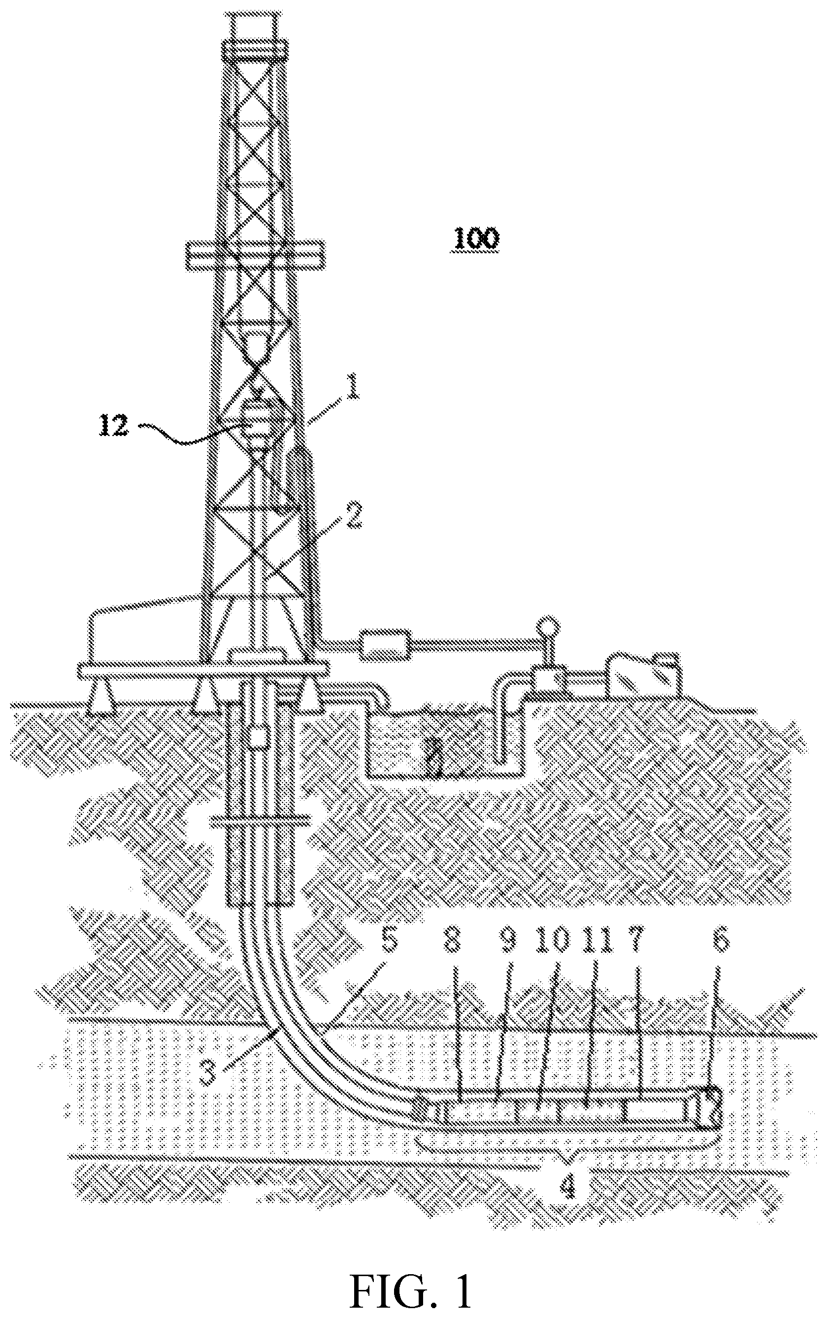
[0017] FIG. 1 is a schematic view illustrating a downhole drilling system according to one embodiment of the present disclosure.
[0018] The downhole drilling system 100 has a derrick 1 on the earth surface. A kelly drive 2 delivers a drill string 3 into a borehole 5. A lower part of the drill string 3 is a bottom hole assembly (BHA) 4, which includes a drill collar 8 with an MWD tool 9 installed therein, an LWD tool 10, a downhole motor 11, a measurement sub 7, and a drill bit 6. The drill bit 6 breaks up the earth formation in the borehole 5, and the downhole motor 11 having a stator and a rotor that rotates the drill bit 6. During a drilling operation, the downhole drilling system 100 may operate in a rotary mode, in which the drill string 3 is rotated from the surface either by a rotary table or a top drive 12 (or a swivel). The downhole drilling system 100 may also operate in a sliding mode, in which the drill string 3 is not rotated from the surface but is driven by the downhole motor 11 rotating the drill bit 6. Drilling mud is pumped from the earth surface through the drill string 3 to the drill bit 6, being injected into an annulus between the drill string 3 and a wall of the borehole 5. The drilling mud carries cuttings up from the borehole 5 to the surface.
[0019] The drill collar 8, which provides weight on the drill bit 6, has a package of instruments including the MWD tool 9 for measuring inclination, azimuth, well trajectory, etc. Also included in the drill collar 8 or at other locations in the drill string are the LWD tools 10 such as a neutron-porosity measurement tool and a density measurement tool, which are used to determined formation properties such as porosity and density. Those tools are electrically or wirelessly coupled together, powered by a battery pack or a power generator driven by the drilling mud. All information gathered is transmitted to the surface via a mud pulse telemetry system or through electromagnetic transmission.
[0020] In this embodiment, the measurement sub 7 is disposed between the downhole motor 11 and the drill bit 6, for measuring various modes of vibration as well as formation parameters, e.g., resistivity, gamma ray, and well trajectory. The data is transmitted through a cable embedded in the downhole motor 11 to the MWD tool 9 or other communication devices, or can be transmitted via a wireless communication protocol. The downhole motor 11 may contain a bent housing (not shown) that is adjustable at the surface. The bent housing allows the drill bit 6 to deviate from the axial direction of the drill string so as to create a curved well-bore. Nevertheless, the bent housing is not adjustable downhole so that the operator cannot adjust the drilling trajectory real time.
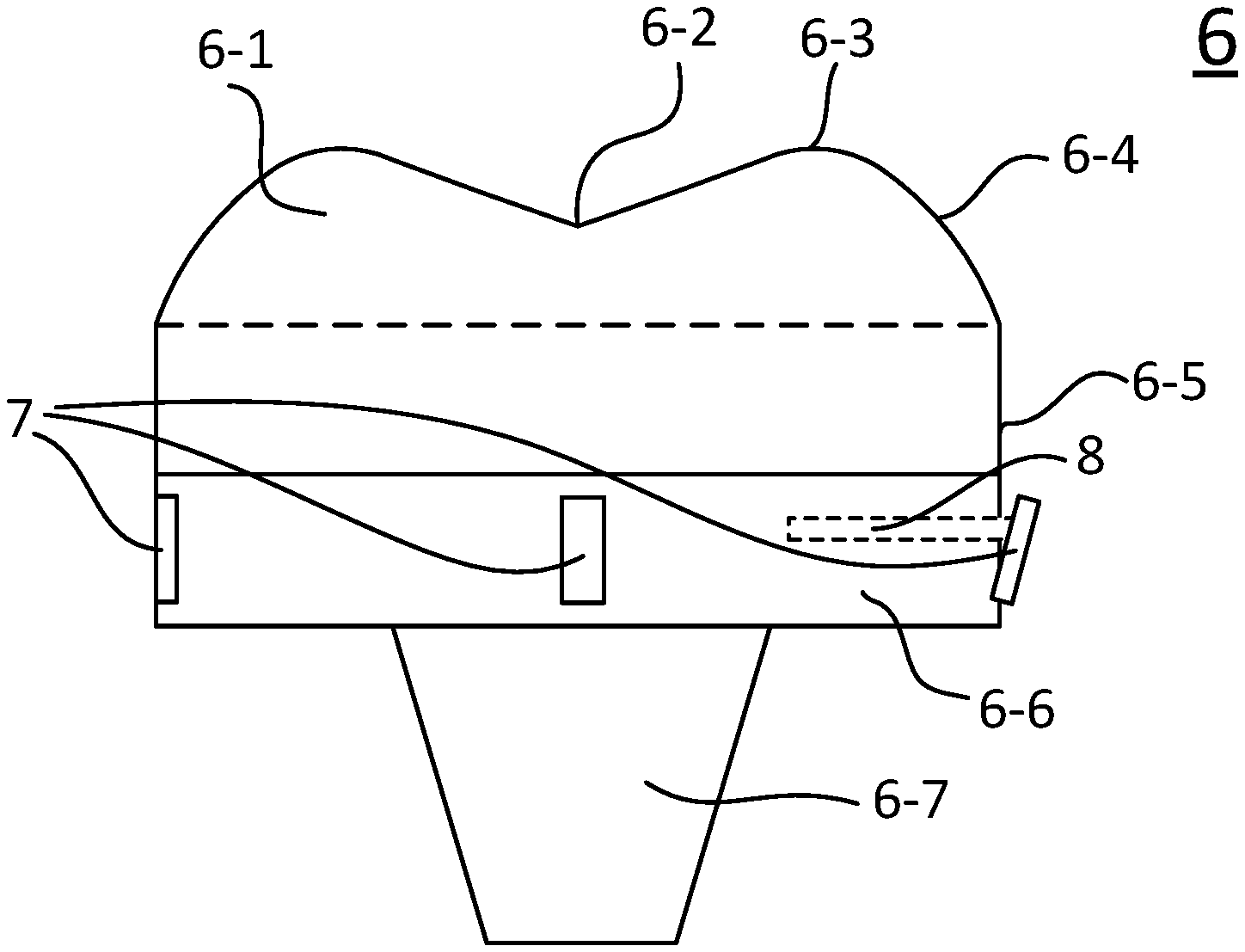
[0021] The drill bit 6 can be a roller-cone bit, a fixed blade bit, or a hybrid bit having both roller-cones and fixed blades. FIG. 2 shows a drill bit of the current disclosure. Similar to traditional roller-cone bits, it has three roller cones 6-1, an apex 6-2, a nose section 6-3, a shoulder section 6-4, a gauge section 6-5. The roller cones have a plurality of cutters installed thereon (not shown). On the other hand, the drill bit has a base section 6-6 adjacent to the gauge section that has the same as or a smaller diameter than the gauge section. The base section contains a plurality of pads or probes 7 that can be extended or retracted. The drill bit 6 has a tapered threaded pin 6-7 to be connected into an internally threaded collar at the lower end of a drill string (now shown).
[0022] Each of the plurality of pads 7 is driven by an actuator or a piston (not shown). The actuators used to drive the pads 7 between their retracted and extended positions can be pistons to which fluid is supplied under pressure, at the appropriate time, through a valve arrangement controlled by the control unit. The valve arrangement can be a rotary valve controlling the supply of drilling fluid from an inlet to a plurality of outlets, in turn, each of the outlets communicating with a respective one of the pistons.
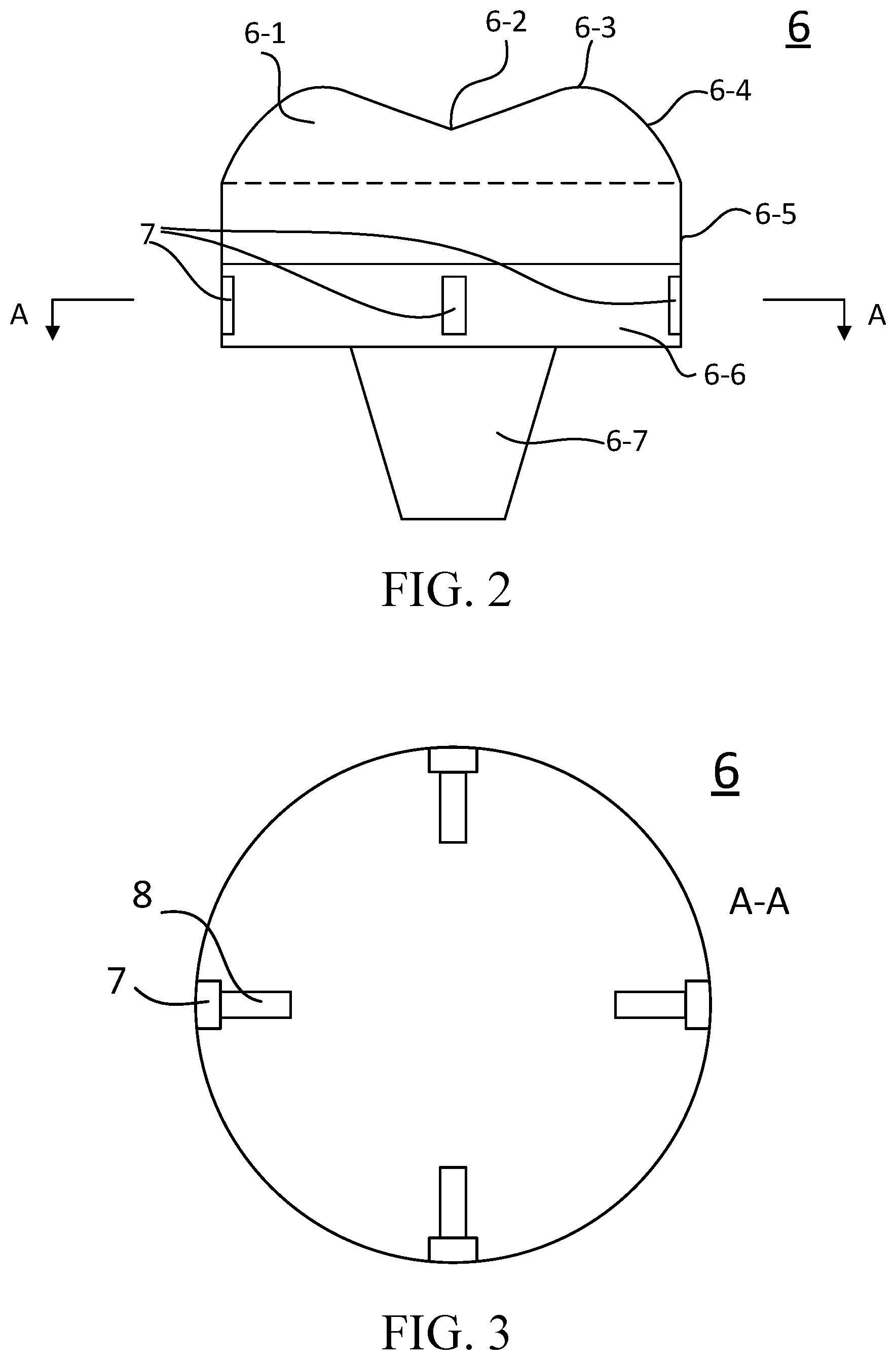
[0023] FIG. 3 is a cross sectional view along the A-A direction shown in FIG. 2, showing the arrangement of the four pads 7 along the circumference of the base section 6-6 in the drill bit and four pistons 8. The number of pads 7 varies according to the diameters of the drill bit. When the drill bit is over 17.5'', two pads are installed. They can either be at 90.degree. or 180.degree. to each other along the circumference of the drill bit. When the diameter of the drill bit is between 9.5'' and 17.5'', three pads at 120.degree. intervals along the circumference of the drill bit are installed. For small drill bits, e.g., of a diameter between 4.75'' and 9.5'', four or six or eight pads can be evenly arranged along the circumference of the drill bit. More pads on the drill bit allow more precise control of the direction of the bit.
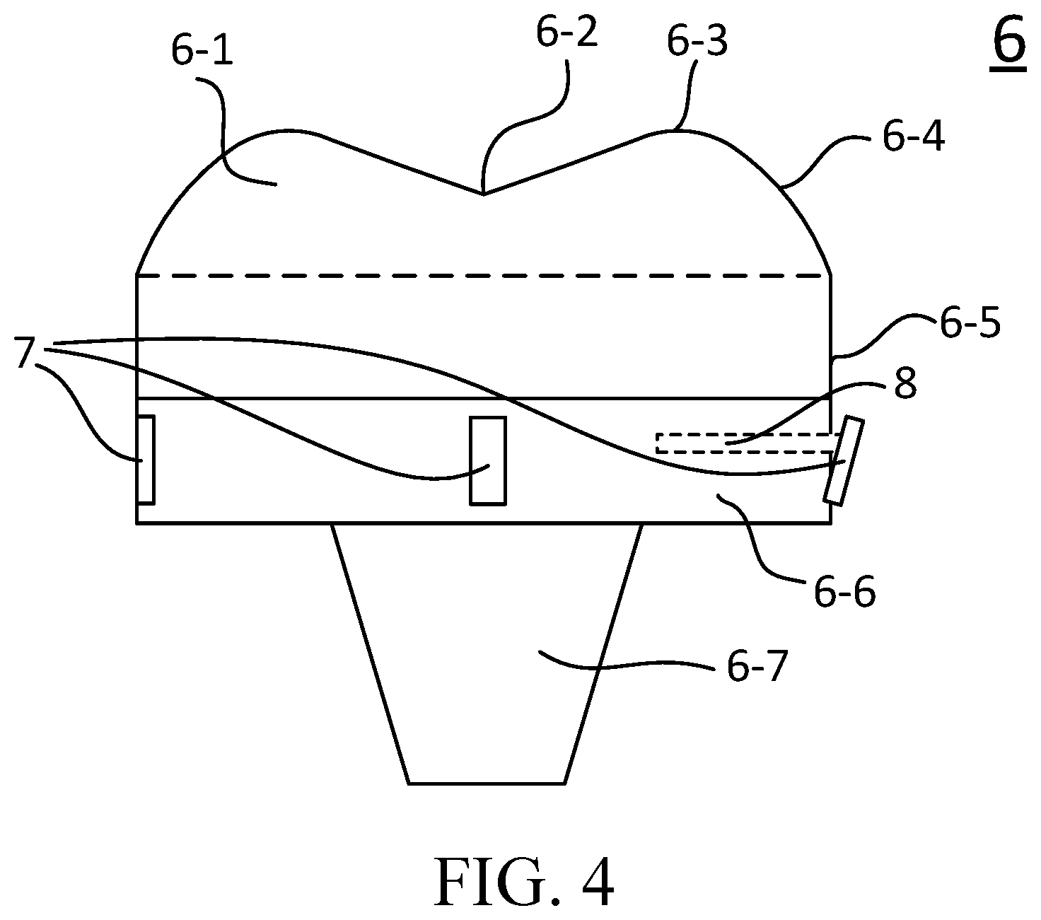
[0024] Each of the pads 7 can be extended out from the circumference of the base section, pushing by a piston 8, as shown in FIG. 8. The piston 8 can be driven by either the hydraulic force or by a high temperature, miniature electric motor. Such miniature motors are available on the market, e.g., from Maxon Precision Motion of Fall River, Mass.
[0025] Furthermore, the pad can be in rectangular, square, circular, or oval in shape. When extended out, the surface of the pad can be either be parallel to the axis of the drill bit. Alternatively, as shown in FIG. 4, the surface of the extended pad 7 can also be at an angel to the axis of the drill bit. The angle can be in the range of 0.degree.-45.degree..
[0026] It is to be understood that the exemplary embodiments described herein are that for presently preferred embodiments and are not limiting. Descriptions of features or aspects within each embodiment should typically be considered as available for other similar features or aspects in other embodiments.
* * * * *
D00000
D00001
D00002
D00003
XML
uspto.report is an independent third-party trademark research tool that is not affiliated, endorsed, or sponsored by the United States Patent and Trademark Office (USPTO) or any other governmental organization. The information provided by uspto.report is based on publicly available data at the time of writing and is intended for informational purposes only.
While we strive to provide accurate and up-to-date information, we do not guarantee the accuracy, completeness, reliability, or suitability of the information displayed on this site. The use of this site is at your own risk. Any reliance you place on such information is therefore strictly at your own risk.
All official trademark data, including owner information, should be verified by visiting the official USPTO website at www.uspto.gov. This site is not intended to replace professional legal advice and should not be used as a substitute for consulting with a legal professional who is knowledgeable about trademark law.