Support Element for Supporting a Window Frame
Deiss; Martin
U.S. patent application number 16/718477 was filed with the patent office on 2020-07-02 for support element for supporting a window frame. This patent application is currently assigned to ISO-Chemie GmbH. The applicant listed for this patent is ISO-Chemie GmbH. Invention is credited to Martin Deiss.
| Application Number | 20200208400 16/718477 |
| Document ID | / |
| Family ID | 64949091 |
| Filed Date | 2020-07-02 |


| United States Patent Application | 20200208400 |
| Kind Code | A1 |
| Deiss; Martin | July 2, 2020 |
Support Element for Supporting a Window Frame
Abstract
A strip-shaped support element for supporting a window frame comprises an intumescent material such as expandable graphite or sodium and/or potassium silicate. In particular, the support element comprises intumescent material on at least one surface, optionally on all surfaces, in a thickness of at least 0.25 mm.
| Inventors: | Deiss; Martin; (Abtsgmuend, DE) | ||||||||||
| Applicant: |
|
||||||||||
|---|---|---|---|---|---|---|---|---|---|---|---|
| Assignee: | ISO-Chemie GmbH Aalen DE |
||||||||||
| Family ID: | 64949091 | ||||||||||
| Appl. No.: | 16/718477 | ||||||||||
| Filed: | December 18, 2019 |
| Current U.S. Class: | 1/1 |
| Current CPC Class: | E04B 1/943 20130101; E04B 1/945 20130101; E04B 1/7641 20130101; E06B 1/02 20130101; E06B 1/6023 20130101; E06B 1/003 20130101 |
| International Class: | E04B 1/94 20060101 E04B001/94 |
Foreign Application Data
| Date | Code | Application Number |
|---|---|---|
| Dec 31, 2018 | EP | 18 215 948.3 |
Claims
1. A strip-shaped support element for supporting a window frame, the strip-shaped support element having a first side surface extending in a longitudinal direction and configured to rest against a wall, and a second side surface extending in the longitudinal direction, wherein the second side surface is substantially perpendicular to the first side surface and is configured to support the window frame, wherein the support element is made of a load-bearing material, wherein the support element comprises intumescent material on at least a surface thereof in a thickness of at least 0.25 mm, which material is selected from the group consisting of: (a) expandable graphite in an amount of 5-70%, and (b) sodium and/or potassium silicate in an amount of 10-30%.
2. The strip-shaped support element according to claim 1, wherein the support element also comprises rigid foam, selected from the group comprising rigid polyurethane foam.
3. The strip-shaped support element according to claim 1, wherein at least one layer parallel to the second side surface of the support element comprises intumescent material.
4. The strip-shaped support element according to claim 1, wherein the support element comprises intumescent material on at least one surface which is a third side surface extending in the longitudinal direction, wherein the third side surface is adjacent to the second side surface on a side opposite the first side surface.
5. The strip-shaped support element according to claim 1, wherein the support element comprises a layered structure with at least one outer layer with intumescent material and at least one layer without intumescent material.
6. The strip-shaped support element according to claim 5, wherein the outer layer with intumescent material is fastened to the layer without intumescent material by adhesion or by screws.
7. The strip-shaped support element according to claim 5, wherein the support element comprises intumescent material in a thickness of between 0.25 mm and 10 mm, and wherein the intumescent material is expandable graphite in an amount of 20-70%.
8. The strip-shaped support element according to claim 1, wherein the support element comprises intumescent material in a thickness of at least 10 mm, and wherein the intumescent material is expandable graphite in an amount of 5-20%.
9. The strip-shaped support element according to claim 1, wherein the support element comprises intumescent material throughout, and wherein the intumescent material is expandable graphite in an amount of 5-20%.
10. The strip-shaped support element according to claim 9, wherein the support element comprises rigid polyurethane foam with 5-10% expandable graphite, obtainable by pressing a starting material, in that expandable graphite flakes in a polyurethane and/or polyisocyanate matrix are pressed in a pressing direction P, wherein the pressing direction P is perpendicular to the second surface of the support element.
11. The strip-shaped support element according to claim 1, wherein the support element comprises intumescent material in a thickness of at least 10 mm, and wherein the intumescent material is sodium and/or potassium silicate in an amount of 10-30%.
12. A building section comprising: a wall; at least one strip-shaped support element having a first side surface extending in a longitudinal direction and configured to rest against a wall, and a second side surface extending in the longitudinal direction, wherein the second side surface is substantially perpendicular to the first side surface and is configured to support the window frame, wherein the support element is made of a load-bearing material, wherein the support element comprises intumescent material on at least a surface thereof in a thickness of at least 0.25 mm, which material is selected from the group consisting of: (a) expandable graphite in an amount of 5-70%, and (b) sodium and/or potassium silicate in an amount of 10-30%; wherein the support element is arranged laterally from the wall, and wherein the support element is fastened to the wall by means of at least one fastening element, wherein the first side surface of the support element rests against the wall; and a window frame, which is supported at least partially on the second surface of the support element.
13. The building section according to claim 12, wherein the building section comprises a plurality of the support elements, wherein: (a) support elements butt directly against each other horizontally, so that the at least one surface comprising intumescent material forms a horizontal fire control barrier without interruption; and/or (b) a fire-retardant layer is introduced horizontally between the support elements, wherein the fire-retardant layer is selected from the group comprising mineral wool.
Description
FIELD OF THE INVENTION
[0001] The invention relates to a strip-shaped support element for supporting a window frame, especially an outer face wall installation casing.
[0002] The invention also relates to a section of a building or a building comprising at least one support element and also the use of the support element for making a building fire-retardant, e.g., as a fire barrier, i.e., for preventing the spread of flames and/or smoke gas upward along the facade of the building, or in/on a composite thermal insulation system, and/or for decreasing the rise in temperature on the side of the support element facing away from the fire.
[0003] Support elements for supporting a window frame, especially outer face wall installation casings, have been used for some years in conjunction with composite thermal insulation systems to extend a wall opening for a window artificially outward. According to EP 2 639 394 A2, a support part of rigid, load-bearing foam is screwed laterally to the wall and serves, especially at the bottom, to support the window frame to be inserted. Thus, for example, an outer wall cooperates with the inner wall to form an intermediate space, in which the support element is arranged. The load-bearing support element with a more-or-less triangular cross section can be supplemented by an insulation part, which consists of hard flexible foam, for example, and which cooperates with the support element to form a two-part body with a preferably rectangular cross section.
[0004] US 2015/0211285 A1 makes available a support element which can be transported and installed very easily.
[0005] One problem with the use of a composite thermal insulation system (or external wall insulation system, EWIS), in which an outer wall installation casing is usually used, is the combustibility of frequently used insulation materials, which comprise, for example, rigid polystyrene foam such as rigid expanded polystyrene foam (EPS) and rigid extruded polystyrene foam (XPS). In particular, when a house is on fire, the flames can spread upward via the facade or possible gaps between the inner wall and the outer wall to the next-higher story, which can lead to the development of a chimney effect.
[0006] US 2018/0312656 A1 describes a functional material which comprises a thermosetting material such as rigid PUR/PIR or phenolic foam, a binder material for binding the thermosetting material, and an additive such as expandable graphite, which is intended to improve the combustion behavior. This material is intended to be used in particular in the form of panels as, for example, thermal insulation elements for outer wall insulation systems or for facade insulation or roof insulation. Coating or impregnating flammable thermal insulation elements and other structural parts such as sealing tape with flame retardants is also known from the prior art; see for example, US 2018/0236754 A1, EP 2 963 198 A1, DE 20 2017 102 227 U1, and U.S. Pat. No. 6,054,513 DE 20 2012 103 609 U1 describes polystyrene foams which are furnished with hexabromocyclododecane (HBCD) as a flame retardant, or which are provided with a jacket of polyurethane foam, which contains flame retardants such as TCPP (trichloropropyl phosphate), TBBPA ester (tetrabromobisphenol ester), or PBDE (pentabromodiphenyl ether).
[0007] Fire control barrier elements made of metal, for example, or of mineral wool or polymer materials are also already known from the prior art; their use in a thermal insulation system is intended to prevent the danger that the fire might spread to the next-higher story. EP 2 088 253 A describes a fire control barrier of polyurethane foam (PUR foam) or polyisocyanate foam (PIR foam) with a homogeneous bulk density in the range of 26 to 80 kg/m.sup.3. In Germany, for example, fire control barriers must be installed in every second story of a high-rise building; in some other countries, they are required in every story.
SUMMARY OF THE INVENTION
[0008] It is an object of the present invention to improve the fire control of additional structural elements of buildings, e.g., of outer wall installation casings, and/or to use such elements to con-tribute to fire control, in particular within the scope of fire control barriers.
[0009] According to an aspect of the invention a strip-shaped support element is provided, which is adapted to the support of a window frame with a first side surface extending in the longitudinal direction, which can serve to rest against a wall, and a second side surface extending in the longitudinal direction, which is substantially perpendicular to the first side surface, and which can serve to support the window frame, wherein the support element is made of a load-bearing material, and wherein the support element comprises intumescent material on at least one surface, optionally on all surfaces, with a thickness of at least 0.25 mm. The intumescent material, i.e., the material with an expansion effect, is selected from the group consisting of:
[0010] (a) expandable graphite in an amount of 5-70%, and
[0011] (b) sodium and/or potassium silicate in an amount of 10-30%.
[0012] The intumescent material is preferably present in a thickness of at least 10 mm, and preferably expandable graphite is present in an amount of 5-20%, more preferably of 5-15% or 7-10%. Within the scope of the invention, the percentages, unless otherwise indicated, are always defined on a weight/weight basis. Expandable graphite can be produced from the naturally occurring material graphite. A graphite flake consists of layers of carbon atoms arranged in honey-comb fashion. Within the layers, the atoms are very strongly connected by covalent bonds. Between the layers, the bonding forces are quite weak, so that molecules can be intercalated between the layers of graphite. The intercalation of an acid, usually sulfuric acid, converts the graphite into expandable graphite. When expandable graphite is heated, the graphite flakes expand to many times their original volume as soon as the temperature reaches approximately 140.degree. C.; the exact temperature depends on the quality of the graphite. The volatilization of the intercalated compounds drives the graphite layers apart like an accordion. The expanded flakes have the appearance of little "worms" and are usually several millimeters long (Vijay J. Bhagat: Behavior of expandable graphite as a flame retardant in flexible polyurethane foam. Presented at: Polyurethane Foam Association (PFA), Arlington, Va., USA, May 10, 2001). The expansion rate of expandable graphite is approximately 30-400 cm.sup.3/g.
[0013] The particles size can be in the range between 80%<75 .mu.m and 80%>1,500 .mu.m. More than 60% of the particles of the expandable graphite are usually at least 100 .mu.m in size or at least 500 .mu.m in size; the average particle sizes are preferably 500-1,500 .mu.m. The larger the particle size, the greater the expansion pressure which develops in the event of a fire. Large particle sizes (300-1,500 .mu.m) are therefore used primarily when a large volume is to be blocked up with foam. The particle size can be determined by means of a sieve analysis according to DIN 66 165, for example.
[0014] The starting temperature of the expansion is at least 140.degree. C., preferably at least 160.degree. C., at least 170.degree. C., or at least 180.degree. C. The starting temperature of the expansion and the expansion rate can be influenced by the fineness of the graphite. On exposure to heat, the expandable graphite expands and forms an intumescent layer on the surface of the material. This slows down the spread of the fire and counteracts the consequences of a fire which are dangerous for people such as the formation of toxic gases and smoke. The expandable graphite is preferably present in an amount of 5-10%, which is sufficient to achieve the fire-retarding effect. If too much expandable graphite is used, different effects are caused, which can have a negative impact on the products desired here. Such a negative effect is an increase in the thermal conductivity of the graphite (Ozturk 2012, Highly Filled Graphite Polymer Compounds for Uses in Heat Management. Dissertation, Technical University of Darmstadt).
[0015] It has been found that the use of expandable graphite offers additional advantages besides the characteristics useful for fire control; for example, materials produced with it generate less dust when processed by operations such as sawing. Such materials can therefore be used to minimize dust formation during processing.
[0016] Alternatively or in addition, the intumescent material can be sodium and/or potassium silicate in an amount of 10-30%, preferably of 10-20%. This waterglass can be produced by solidification from a melt. Particles, e.g., particles with a size of approximately 0.1-5 mm, with an average size of 1 mm, can be embedded in the foam matrix to achieve advantages.
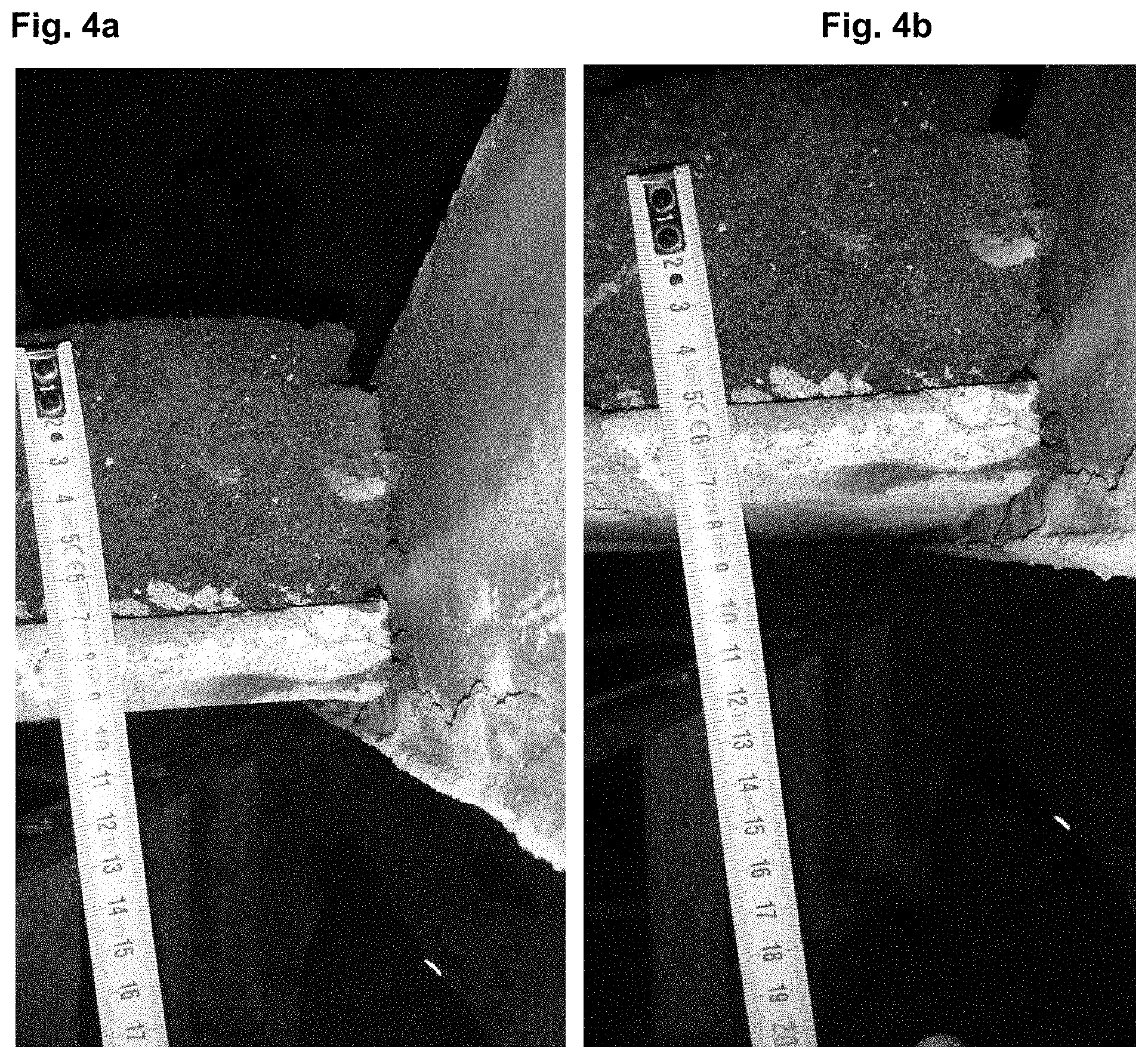
[0017] The support element also comprises a least one polymer, preferably a thermoset. A support element with rigid foam, e.g. rigid PUR foam, preferably rigid polyurethane/polyisocyanate foam, rigid PIT foam, or rigid phenolic foam, offers especially good mechanical and heat-insulating properties. In a preferred embodiment, the support element comprises comminuted rigid PUR and/or rigid PIR foam and/or comminuted rigid phenolic foam as the thermosetting material, which is bound at least under the action of heat, for example, by a binding material, preferably PUR and/or PIR which is in the form of a liquid or paste at room temperature (25.degree. C.). Within the scope of production, these components are treated jointly with the introduced intumescent material by heat and/or pressure, usually by both. The particle size of the intumescent material is preferably 0.1-2 times the size of the comminuted rigid foam particles, best of all approximately the same size, for the purpose of ensuring good mixability.
[0018] Fibrous materials, e.g., mineral fibers or nonmineral fibers, can also be introduced into the starting material before the pressing step; carbon fibers can be used here.
[0019] The starting material is pressed in particular in a pressing direction P. The starting material, which comprises expandable graphite, for example, is preferably pressed in a pressing direction P to a bulk density of 500-600 kg/m.sup.3. The support element consists substantially of the polymer, e.g., a rigid PUR/PIR foam, as described herein, in addition to the intumescent material. The proportion of the polymer (comminuted rigid foam and binder material together) can be 40-97%, for example; in combination with expandable graphite, it can be, for example, 70-97%, preferably 80-95% or 90-95%. Because recycled thermal insulation panels can be used as the comminuted thermoset material, contaminants such as the foil material, e.g., aluminum foil, ap-plied to these panels can be introduced. The support element is preferably halogen-free. The amount of binder material is usually no more than 20%, and the amount of comminuted rigid foam is usually approximately 60-75%.
[0020] Panels produced by the pressing step can be cut into strip-shaped support elements, wherein the production of L-shaped support elements can be accomplished by milling, for example, or by bonding a wider element to a narrower one.
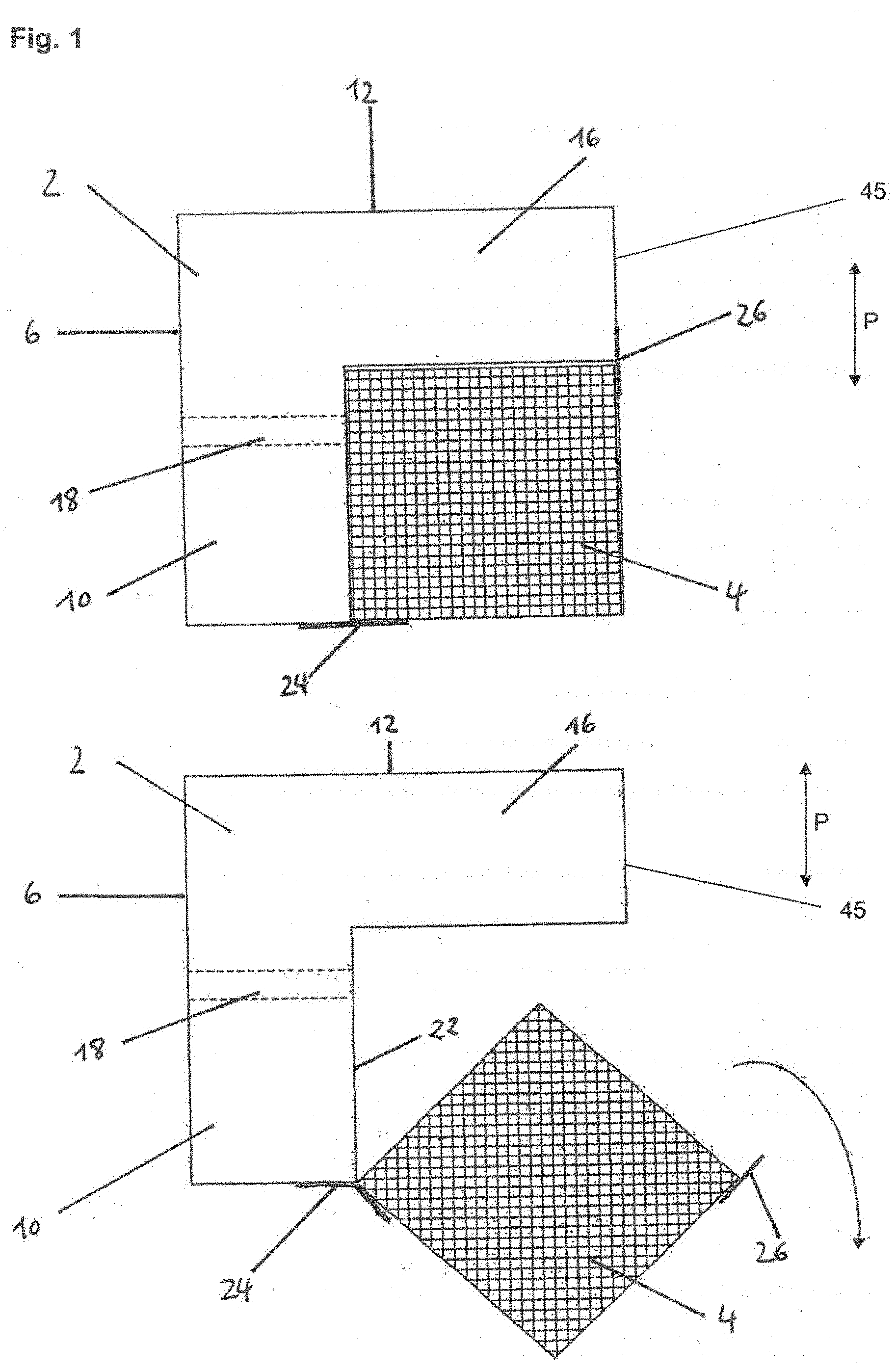
[0021] In one embodiment, the support element consists of a substantially homogeneous material; that is, the intumescent material is introduced not just into one or more layers but rather continuously throughout. The whole or the entire support element therefore consists substantially of the mixture with the intumescent material. For example, the support element can consist of a polymer, especially one based on PUR or PUR/PIR such as a rigid polyurethane foam, together with expandable graphite (e.g., 5-10%); the element can be produced by pressing a starting material, in that expandable graphite flakes in a polyurethane matrix are pressed in a pressing direction P to a bulk density of 500-600 kg/m.sup.3. In a preferred embodiment, the support element consists of comminuted rigid PUR and/or PIR foam, which is bound by a binding material, e.g., PUR and/or PIR in the form of a liquid or paste. As part of the production process, these components are treated together with the introduced intumescent material, e.g., expandable graphite, by pressure, optionally at elevated temperature, in a pressing direction P. The bulk density of the material is, for example, 300-1,000 kg/m.sup.3, 500-600 kg/m.sup.3, or approximately 550 kg/m.sup.3.
[0022] The material used preferably exhibits a combustion behavior according to at least one of the reaction-to-fire classes C defined in DIN EN 13501-1 and/or correspondingly to at least one construction material class B1 according to DIN 4102-1 and thus is classified as flame-retardant.
[0023] The inventors discovered that, in a fire, e.g., on exposure to flame for 30 minutes at 180.degree. C., the intumescent material on the side facing the fire expands from a layer with a thickness of approximately 10 mm to form an insulating layer. In one embodiment, the support element therefore comprises on at least one surface, optionally on all surfaces, intumescent material in a thickness of at least 10 mm. This is advantageously present substantially over the entire plane or over the entire plane of this surface. The intumescent material, i.e., the particles of this intumescent material, are distributed substantially homogeneously at least within this thickness. The intumescent material in this embodiment is not a coating on the surface of the support element but rather is embedded in the matrix of the support element.
[0024] In a preferred embodiment, at least one layer parallel to the second side surface of the support element comprises the intumescent material, preferably the second side surface of the support element. The second side surface of the support element extending in the longitudinal direction is substantially perpendicular to the first side surface, which can serve to contact a wall. The second side surface can serve to support a window frame.
[0025] The longitudinal direction is defined by the longest dimension of the strip-shaped element. The strip-shaped element can be present without any connection to any other elements, but it can also be already installed, e.g., in a section of a building, perhaps as an outer wall installation casing for a window, for example, or for a door.
[0026] In the installed state as a casing, perhaps as an outer wall installation casing, the second side surface of the support element forms the inside surface of the casing facing the window frame. Thus, in a fire, the exterior area of this side surface is exposed to the flames to a pronounced degree, especially above the window opening, from which, in a fire, flames can spread. A fire-inhibiting or fire-retardant surface at this point, which comes about through the intumescent action of the material, e.g., the expansion of the expandable graphite, can thus prevent the flames from spreading to material located above the window opening, e.g., combustible insulating material of a composite outer wall insulation system, or can at least significantly delay such spread. Even in the case of a fire which spreads within the composite outer wall insulation system, the support element thus offers an effective barrier, which can prevent or significantly delay any further upward propagation.
[0027] On the side facing the window frame, the expansion of the expandable graphite also effectively prevents a sealing tape, which is usually attached between the casing and the window frame, from having a fire-promoting effect. Any gaps which may form are sealed off by the expansion.
[0028] If, alternatively or in addition, the layer comprising the intumescent material parallel to the second side surface of the support element is not the second side surface itself, then the side surface in question will be the side surface facing away from the window opening in the installed state, which therefore means that the surface in question is the bottom surface of the casing, for example, which also represents an effective horizontal barrier against the upward spread of a fire in or on a building.
[0029] Other locations critical with respect to the spread of fire are the joints which can be present between the casing and an optional outer wall present in the building. Combustible insulating materials located between the main wall and the outer wall can ignite rapidly in the event of a fire, wherein the fire, if no additional structural measures have been taken, can spread upward very quickly through this intermediate space. For example, because of different distances between the main wall and the outer wall or because of the need for a gap to ensure the rear ventilation of the outer wall, joints are often present in a building between the casing and the outer wall, which can often have a width of some millimeters, e.g., 10-200 mm. The vertical spread of a fire through these joints can be prevented or at least significantly delayed. The penetration of smoke through such joints can also be minimized.
[0030] According to an aspect of the invention, the support element can comprise intumescent material on at least one surface which represents a third side surface extending in the longitudinal direction, this third surface being adjacent to the second side surface on the side opposite the first side surface. The third side surface is preferably parallel to the first side surface, e.g., in the case that the support element is in the form of an L. In the installed state, this side can thus be facing the outer wall. When the expandable graphite on this side surface expands, a joint potentially located there is advantageously sealed off, so that the spread of flames through the joint can be prevented. This advantage is also offered by a support element with a triangular shape, although to a lesser extent, depending on the angle.
[0031] Substantially all surfaces (e.g., at least 90% of the surface area) or all surfaces of the support element comprise the intumescent material. Optionally, the first side surface, which can serve to rest against a wall, comprises no intumescent material, because the wall usually does not consist of a combustible material.
[0032] The intumescent material can be present in a thickness of at least 10 mm, approximately in a thickness of 11-50 mm, 12-40 mm, 15-30 mm, or 10-20 mm. Then the amount of expandable graphite is preferably in the range between 5 and 20%.
[0033] Alternatively, the intumescent material can be present in a thickness of between 0.25 mm and 10 mm, preferably between 0.5 mm and 5 mm, more preferably between 1 mm and 3 mm. In this case, the amount of expandable graphite is between 20 and 70%, preferably between 30 and 60%.
[0034] Preferably at least all surfaces of the support element except for the first side surface comprise the intumescent material, or all surfaces of the support element comprise it.
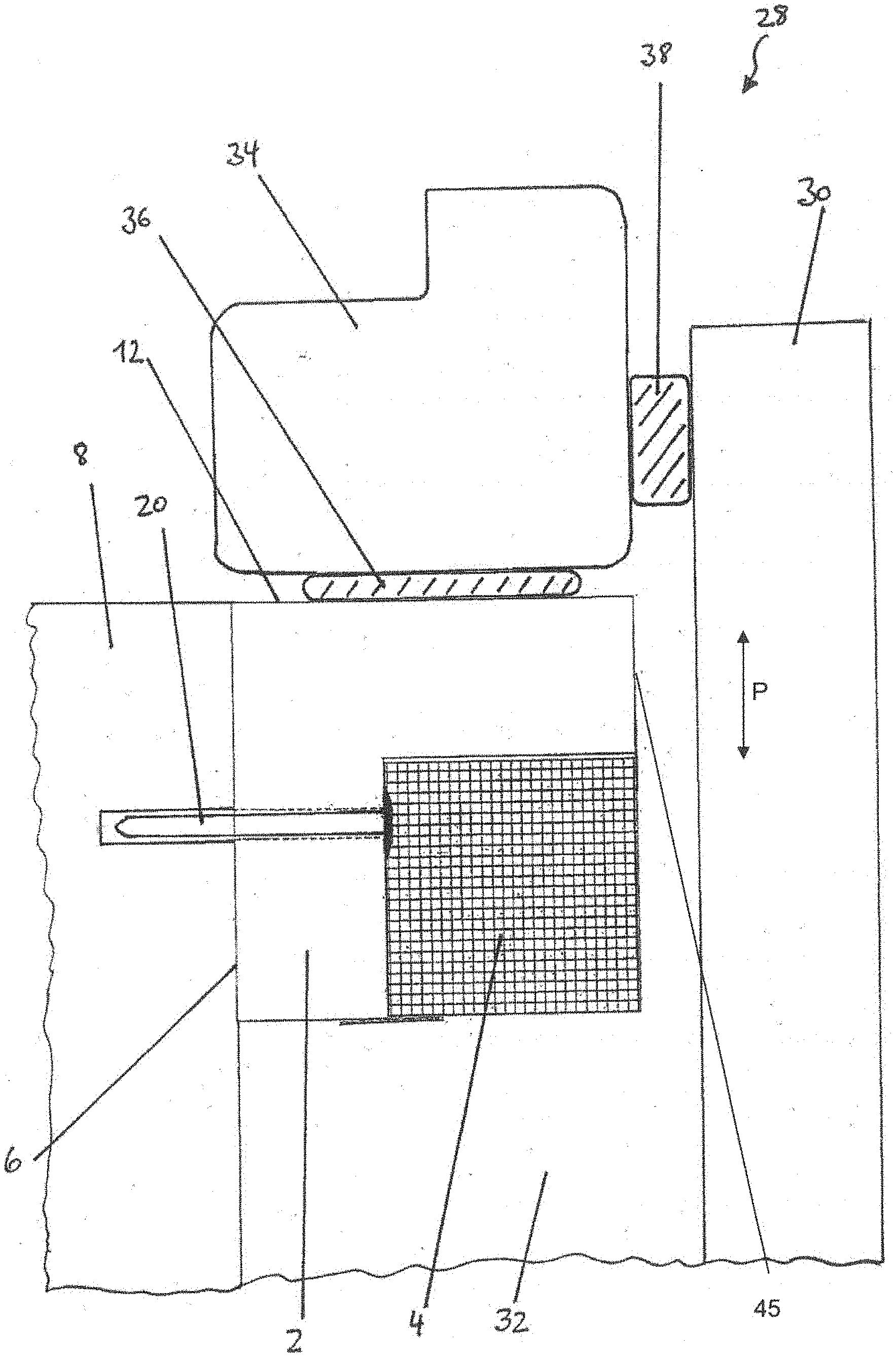
[0035] As the inventors have been able to show, however, it is not mandatory that intumescent material also be present in the interior of the element. The support element can therefore comprise a layered type of structure. In one embodiment, the support element comprises at least one layer with a load-bearing property which exceeds the load-bearing property of the material on the surface comprising the intumescent material. An interior layer of this type capable of bearing heavy loads can, for example, comprise a compressive stress at 10% compression of 2 to 15 MPa, preferably of 4-8 MPa, or especially preferably 6 to 8 MPa, according to DIN EN 826. It can comprise fibrous material, for example, such as carbon fibers and/or glass fibers. The interior material can, alternatively, comprise substantially the same load-bearing capacity as the outer material. Optionally, the interior material consists of the same material as the outer layer(s) except for the intumescent material. In this case, the layered structure leads in particular to a cost reduction, because less intumescent material is required.
[0036] A layered construction can be produced by connecting the various layers together (e.g., by bonding them together with an adhesive or by screwing them together). It is also possible, however, to produce a layered construction in that the different layers of comminuted rigid PUR and/or PIR foam, i.e., outside layers with intumescent material (e.g. expandable graphite) and inside layers with no intumescent material, are mixed with a binder such as PUR and/or PIR liquid or paste, and, as part of the production process, pressed together under pressure and optionally at elevated temperature in a pressing direction P, which is perpendicular to the direction of the layers. The outer layers with intumescent material comprise a thickness of at least 10 mm. The support elements can be produced from panels formed in this way.
[0037] The support element is made of a load-bearing material; that is, it comprises overall a load-bearing property or a compressive strength which is at least sufficient to support a window. The compressive stress at 10% compression is preferably 2-15 MPa, especially 4-8 MPa, or 6-8 MPa according to DIN EN 826.
[0038] As the inventors discovered, the pressing direction P during the production of the raw material for the support element has an influence on the structure of the raw material and thus also on the properties of the support element on exposure to fire. Various orientations attributable to production conditions are possible both for support elements made of a homogeneous material and for those with a layered structure. In particular, the support element can be configured in such a way that the pressing direction P used during production is perpendicular to the first side surface of the support element, or so that the pressing direction P relevant to production is perpendicular to the second side surface of the support element.
[0039] It was discovered that the expansion of the intumescent material on a surface perpendicular to the pressing direction P leads to greater dimensional increase during a fire than it does on a surface parallel to the pressing direction P. As described herein, 30 minutes of exposure to flame causes an approximately 1-cm-thick layer of expandable graphite on a surface perpendicular to the pressing direction P to expand into an approximately 8-cm-thick insulating layer of expanded graphite. In contrast, 30 minutes of exposure to flame, as described herein, causes an approximately 1-cm-thick layer on the surface parallel to the pressing direction P to form an insulating layer of expanded graphite only about 4 cm thick.
[0040] The support element is preferably configured so that the pressing direction P is perpendicular to the second side surface of the support element. The support element can in particular comprise rigid polyurethane foam, preferably with 5-10% of expandable graphite, obtainable by pressing a starting material in which expandable graphite flakes in a polyurethane and/or polyisocyanate matrix are pressed in a pressing direction P to obtain a bulk density of 500-600 kg/m.sup.3, wherein the pressing direction P is perpendicular to the second side surface of the support element. During a fire, this offers two essential advantages:
[0041] First, an especially thick insulating layer of expanded graphite is formed on the surface of the support element which is parallel to the second surface of the support element, namely, on the surface which is especially important for fire control, as described herein, especially for the prevention of the upward spread of flames. As a result, a burn-through is prevented or at least significantly delayed.
[0042] Second, expansion occurs toward the main wall and toward the outer wall; this expansion is sufficient to seal off any joints which may be present. Nevertheless, the expansion and thus also the pressure on the main wall or outer wall are weaker than they would be if the orientation of the support element were reversed. As a result, a lighter load is exerted on the structural integrity of the adjacent construction elements. During a fire, there is less movement in the body of the building. The formation of cracks in the outer wall, which could allow the fire to spread or parts of the building to fall down, is minimized.
[0043] An alternative embodiment is the application of a thin outer layer with intumescent material in a thickness of between 0.25 mm and 10 mm, preferably between 0.5 mm and 5 mm, more preferably between 1 mm and 3 mm, to a surface of the support element. For this purpose, the outer layer is attached to the layer without intumescent material, preferably adhesively bonded. The outer layer is preferably in the form of strips. The outer layer can but does not necessarily have to cover the entire surface area of this side of the support element. In these cases, the intumescent material must comprise expandable graphite in an amount of 20 to 70%, preferably of 30 to 60%.
[0044] Because the support element is itself a good thermal insulator, it can be used without any additional insulating materials. The support element, however, is preferably used together with an insulating part, which can be bonded to the support element to improve the thermal insulating capacity. The insulating part is preferably made of foam or mineral wool, preferably of hard flexible foam. This foam should preferably be self-supporting. Thermal insulation materials such as polystyrene, Styropor, Styrofoam, or Neopur, for example, can be considered. The insulating part can be made of flexible foam such as hard flexible foam.
[0045] To facilitate the on-site installation work, at least one through-hole is introduced in advance through a first web of the support element, proceeding from the inner side surface to the first side surface, to accept a fastening element for attaching the support element to the wall. The installer therefore does not have to produce the through-hole at the installation site.
[0046] A geometry which is especially preferred is present when the cross section of the support element has substantially the shape of an "L". This ensures that the support element has no slanted edges, which would make it difficult to handle the support element when producing the through-holes or when inserting fastening elements into the through-holes.
[0047] In one variant, the support element can also have a cross-section in the form of a "T", or it could also be a rectangular.
[0048] The second web usually comprises the second side surface, and the first and second side surfaces also intersect at the same angle at that by which the second web projects from the first web. This pertains in particular to the configuration of the support element with an L-shaped cross section.
[0049] It is also possible, however, that the first web could also comprise the second side surface, which would then be arranged adjacent to the first side surface. This configuration is unavoidable in the case of a T-shaped cross section, but it can also be present in an L-shaped support element.
[0050] In one embodiment, a casing, such as an outer wall installation casing, is provided which comprises several support elements, each of which comprises a surface comprising intumescent material. The casing can be part of a section of a building.
[0051] According to another aspect of the invention, a section of a building with a wall is provided, with at least one support element arranged laterally from the wall, which support element is attached to the wall by means of at least one fastening element, so that the first side surface of the support element rests against the wall; and with a window frame, at least part of which is supported on the second side surface of the support element.
[0052] A building section equipped with the support elements usually comprises a main wall, an outer wall, and a gap between the main wall and the outer wall. The support elements are usually arranged in the gap between the main wall and the outer wall and are attached to the main wall by fastening elements. A window frame is arranged adjacent to the gap and rests against the second side surfaces of the support elements. It is possible for only one support element to be present, which is arranged under the window frame and thus bears the load of the window. As an alternative to the outer wall, a layer of thermal insulation attached to the main wall can be provided, which has an opening for the window. The support element then projects into this layer of thermal insulation. The building section can comprise a composite thermal insulation system, a rear-vented facade, or a double-shell masonry wall.
[0053] The building preferably comprises a building section and a composite thermal insulation system, a rear-vented facade, or a double-shell masonry wall and usually at least one window.
[0054] A building section or a building can also comprise a plurality of support elements. In one embodiment of the building section, support elements can advantageously be configured as a continuous row of horizontal elements in that, for example, they abut one another directly. Thus at least one surface of the support element forms a continuous horizontal fire control barrier. This can be achieved in that a substantially continuous horizontal window facade is formed, which is installed with the support elements. Alternatively, it is also possible to provide only a single continuous support element.
[0055] Alternatively, the support elements can be a certain distance apart, wherein a fire-retardant layer is introduced horizontally between the support elements, wherein the layer can comprise mineral wool or some other material of low flammability.
[0056] Such fire control barriers can be provided in every story, for example, or in every second story of the building.
[0057] Another aspect of the invention is the use of a strip-shaped support element or building section to make a building fire-retardant. In one embodiment, this use serves to prevent or at least significantly to delay the upward spread of flames and/or smoke gas, especially in a composite thermal insulation systems, a rear-vented facade, or a double-shell masonry wall.
[0058] In another embodiment, this use serves to minimize the increase in temperature on a side of the support element facing away from a fire. As described in the example section, it was found that the temperature increase on a side of the support element facing away from a fire is considerably smaller than that for a support element according to the prior art, especially at butt joints. The support elements can thus be used so that, on exposure to flames (e.g., at 180.degree. C. according to DIN 1366-4), the temperature increase on the side facing away from the flames is minimized at butt joints between adjacent support elements, wherein the increase is preferably less than 55.degree. C. after 25 minutes.
BRIEF DESCRIPTION OF THE DRAWINGS
[0059] The patent or application file contains at least one drawing executed in color. Copies of this patent or patent application publication with color drawings) will be provided by the Office upon request and payment of the necessary fee.
[0060] FIG. 1 shows cross-sectional views of a first embodiment of a support element according to the invention, wherein the lower diagram represents an insulating part during the pivoting procedure;
[0061] FIG. 2 shows a schematic, cross-sectional view of a building section, which shows a support element according to FIG. 1 in the installed state;
[0062] FIGS. 3a-3h show views of alternative support elements according to the invention;
[0063] FIGS. 4a and 4b show, from the side (above, in the figure), embodiments of support elements according to the invention with homogeneously distributed expandable graphite exposed to flames for 30 minutes;
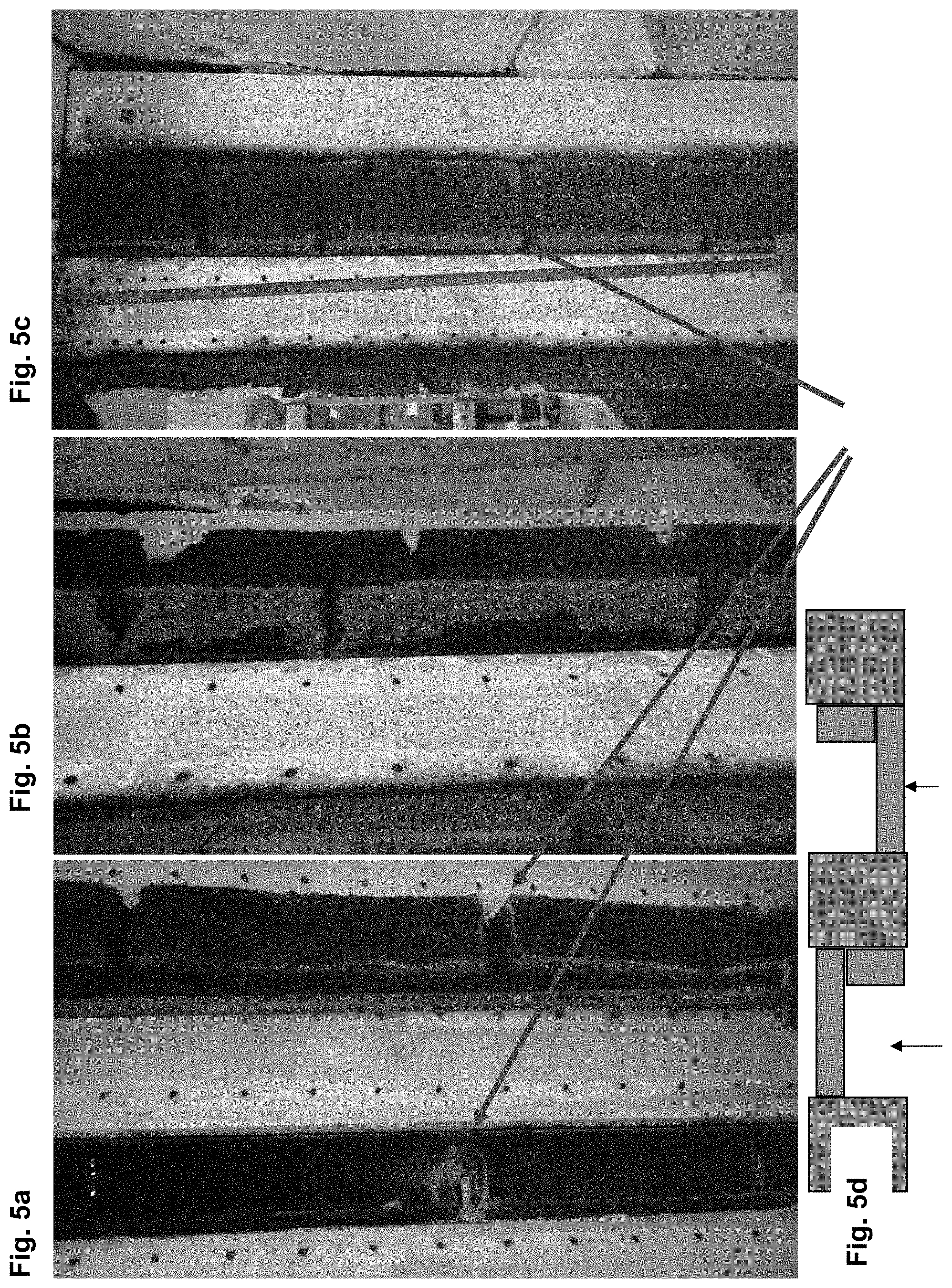
[0064] FIGS. 5a, 5b, and 5c show the results of the flame-exposure experiments with embodiments of support elements according to the invention with homogeneously distributed expandable graphite with an expanded graphite layer on the flame-exposed side;
[0065] FIG. 5d shows the layout of the flame-exposure experiments, wherein the arrows indicate the direction of the flames in the various experiments; and
[0066] FIGS. 6a and 6b show the different ways in which insulating layers are formed during the expansion of the graphite from a support element according to the invention as a function of the orientation of the pressing direction.
DETAILED DESCRIPTION OF SPECIFIC EMBODIMENTS
[0067] FIG. 1 shows a first embodiment of the support element according to the invention for supporting a window frame. The cross section of the support element 2 has the shape of an angle. An insulating part 4 with a rectangular cross section can be connected to the support element 2. The insulating part 4 can also have a different shape, however, or it can be omitted entirely.
[0068] The support element 2 extends primarily in a longitudinal direction. The length of a support element 2 in the longitudinal direction can be freely selected and is preferably between 10 and 150 cm. The support element 2 can be a one-piece unit, or it can consist of two pieces bonded permanently to each other. In the embodiment shown, the support element 2 has an L-shaped cross section. The shape of the support element 2 can also be rectangular or comprise a beveled surface. The support element 2 is made of a load-bearing material, which is adapted to bearing the load of the window fame without itself undergoing deformation.
[0069] It is preferred that the material of the support element 2 have a compressive stress at 10% compression according to DIN EN 826 in the range from 2 to 15 MPa, especially in the range from 4 to 8 MPa. The bulk density of the material should be in the range from 100 to 1,200 kg/m.sup.3, preferably between 350 and 800 kg/m.sup.3. The thermal conductivity of the rigid foam material should be in the range from 0.05 to 0.2 W/mK, preferably in the range from 0.06 to 0.15 W/mK. The material is dimensionally stable and compressively stable under the load of the window.
[0070] The support element 2 comprises a first side surface 6 extending in the longitudinal direction, which serves to rest against a wall 8 (FIG. 2). The first side surface 6 is part of a first web 10 of the support element 2. The support element 2 also comprises a second longitudinally extending side surface 12, which is substantially perpendicular to the first side surface 6 and which serves to support a window frame 34 (FIG. 2). In the exemplary embodiment shown here, the second side surface 12 is part of a second web 16 of the support element 2, which is connected to the first web 10 and projects at an angle from the first web 10. In the example shown here, the angle is 90.degree.. The first side surface 6 and the second side surface 12 meet along one edge and also intersect at the same angle as the two webs 10, 16, i.e., therefore at 90.degree. in this case. The second side surface 12 and the third side surface 45 also meet along an edge and intersect at an angle of 90.degree. in the preferred embodiment illustrated.
[0071] In the first web 10, one or preferably several through-holes 18 can be provided, which allow the passage of one or more fastening elements 20 (FIG. 2) such as screws. Each through-hole 18 therefore passes through the first web 10 of the support element 2 from an inner side surface 22, which is opposite the first side surface 6, to the first side surface 6. As can be derived from FIG. 2, each fastening element 20 serves to fasten the support element 2 to the wall 8.
[0072] It is also possible not to provide any through-holes 18 in the first web 10 of the support element in advance. Instead, the through-holes are introduced into the support element 2 by the installer only after it has arrived at the installation site.
[0073] The insulating part 4 is arranged in the area of the inner side surface 22 of the first web 10 of the support element 2. It is preferably made of foam or mineral wool, especially preferably of hard flexible foam. Such foams are usually self-supporting but cannot bear any load. Examples of materials of this type include polystyrene, Styrodur, Styropor, Styrofoam, or Neopur, with bulk densities of <100 kg/m.sup.3, preferably <50 kg/m.sup.3, which are known as thermal insulation materials. The compressive strength of such insulating materials is preferably at most 50% of the compressive strength of the load-bearing rigid foam used for the support element 2, usually less than 20% of that strength.
[0074] The insulating part 4 is pivotably connected to an outer edge area of the first web 10 of the support element 2. It could also be pivotably connected to an outer edge area of the second web 16 of the support element 2. At the top of FIG. 1, the insulating part 4 can be seen in its insulating position, in which the insulating part 4 covers at least most of the inner side surface 22 of the first web 10 of the support element 2; in the present case, it covers that surface completely. In this position, the insulating part 4 rests preferably against both the first web 10 and the second web 16 of the support element 2. It is especially preferred that the support element 2 and the insulating part 4 fit together in such a way that they form a rectangular cross section. The combination of the support element 2 and insulating part 4 is preferably also transported in this insulating position.
[0075] The lower part of FIG. 1 shows the insulating part 4 as it is being pivoted; it is on its way into a working position, in which it exposes at least most of the inner side surface 22 of the first web 10 of the support element 2. In this working position of the insulating part 4, the fastening elements 20 can be introduced into the through-holes 18 without hindrance. If no through-holes 18 are present in the support element 2, the installer has free access to the first web 10 of the support element 2 when the insulating part 4 is in this working position and can produce the through-holes 18 there before he introduces the fastening elements 20 through the through-holes 18 and into the wall 8. The pivot angle between the working position and the insulating position of the insulating part 4 is usually between 60.degree. and 120.degree., but there are no limitations. The pivotable connection between the insulating part 4 and the support element 2 is preferably achieved by a flexible adhesive strip 24, which is adhered both to the insulating part 4 and to the support element 2. In the embodiment shown in FIG. 1, the adhesive strip 24 is configured as a flat, straight covering over the butt joint between the support element 2 and the insulating part 4. Many other arrangements of the adhesive strip 24, however, can also be envisioned.
[0076] The skilled person can also conceive of many other possible ways of realizing the pivoting connection between the insulating part 4 and the support element 2 besides the adhesive strip 24. For example, the insulating part 4 and the support element 2 could be connected to each other by a different type of element such as an elastic element; a small area of the insulating part 4 could also be laminated directly to the support element 2; or some other mechanical pivoting connection could be realized between the insulating part 4 and the support element 2.
[0077] In the embodiment shown in FIG. 1, furthermore, a second adhesive strip 26 is provided, which connects the edge area of the second web 16 of the support element 2 to the insulating part 4. This adhesive strip 26 should be easily detachable at least from the support element 2, because it must be removed from the support element 2 before the insulating part 4 can be pivoted into the working position (FIG. 1, below). The adhesive strip 26 is preferably reusable, so that, after the support element 2 has been fastened to the wall 8 and the insulating part 4 has been pivoted back into the insulating position, it can be reattached to the support element 2. Instead of the second adhesive strip 26, the detachable connection between the insulating part 4 and the second web 16 of the support element 2 can also be realized in some other way.
[0078] If the pivotable connection is created between the second web 16 of the support element 2 and the insulating part 4, then logically the detachable adhesive connection between the insulating part 4 and support element 2 will be between the insulating part 4 and the first web 10 of the support element 2.
[0079] In principle, however, the pivotable connection between the insulating part 4 and the support element 2 can also be the only connection between these two components. The insulating part 4 should then remain in the insulating position without any external influence; for example, as a result of an appropriate selection of the size and shape of the support element 2 and of the insulating part 4, the insulating part can wedge itself detachably between the inner side of the support element 2 perpendicular to the inner side surface 22 and the pivoting connection.
[0080] The insulating part 4 can also be configured in such a way that the surface of the insulating part 4 arranged adjacent to the inner side surface 22 of the support element 2 leaves enough free space to accommodate the portions of the fastening elements 20 which may be projecting from the inner side surface 22 (not shown in the drawing).
[0081] FIG. 2 sketches the installation situation of a support element 2 according to the invention, wherein the orientation of the support element 2 represents the situation in which the element is installed below the window opening. On the other three sides of the window opening, the support element 2 must be rotated as appropriate. In addition to the wall 8, to which the support element 2 is fastened by means of the fastening elements 20, the illustrated building section 28 usually also comprises an outer wall 30, which is usually made of a thermally insulating material. This outer wall is rear-vented, and the support element 2 is arranged in the intermediate space 32 between the main wall 8 and the outer wall 30. The outer wall 30 is usually connected to the main wall 8 by struts, projections, or pins. The window frame 34 is usually arranged adjacent to the intermediate space 32 and is supported on the second side surface 12 of the support element 2. Sealing elements 36 made of PUR foam, for example, can also be inserted between the window frame 34 and the support element 2. Sealing elements 38 made of PUR foam, for example, can also be arranged between the window frame 34 and a projecting part of the outer wall 30, i.e., a part which projects beyond the height of the support element 2.
[0082] The strip-shaped support elements are usually arranged around the entire window opening. It is also possible to install one or more support elements only underneath the window opening, because here is where most of the weight of the window is supported.
[0083] In cases where the window frame 34 is surrounded on all sides by support elements, the one or more support elements on the bottom of the window opening are usually connected to the wall 8 by screws or the like. At this point, but especially on the other sides of the window opening, it is possible under certain circumstances that an adhesive bond between the support element 2 and the wall 8 can also be sufficient. The adhesive bond can also be advantageous when fastening is achieved by means of the fastening elements 20. The adhesive can preferably serve simultaneously as a diffusion barrier as well.
[0084] The length of a support element usually corresponds exactly to the corresponding length or width of the window opening. Nevertheless, it is also possible to arrange several support elements in a row along each side of the window opening. The individual support elements are usually mitered and either butt up against each other or are preferably attached to each other, especially by means of an adhesive.
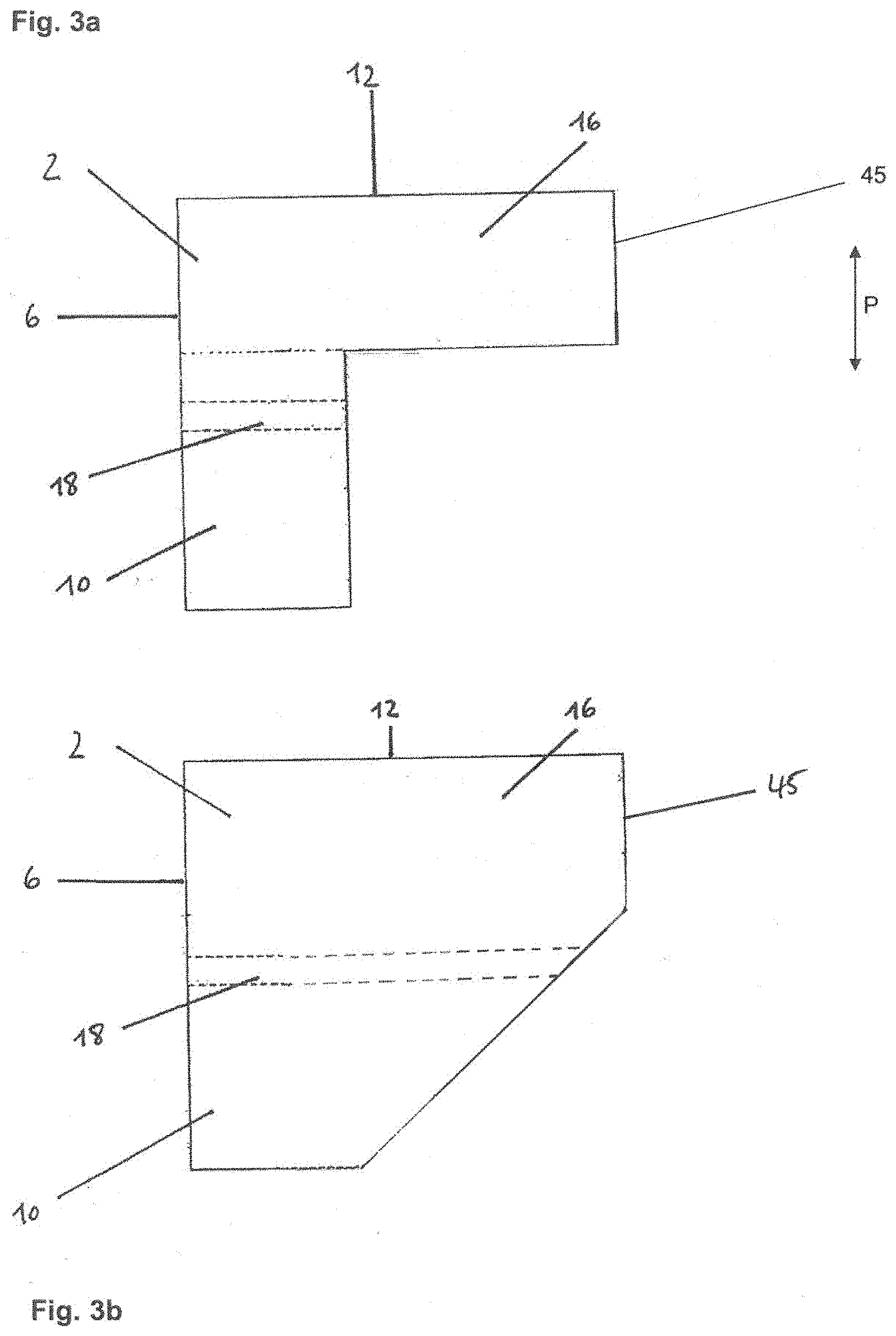
[0085] FIGS. 3a-3h show additional alternatives of the support elements according to the invention.
[0086] The support element 2 in FIG. 3a corresponds to the support element of FIG. 1 with the difference that there is no insulating part here. It is provided intumescent material continuously throughout. An insulating part is also absent from the other embodiments described below, but it could just as well be present in each of them.
[0087] The support element 2 of FIG. 3b corresponds to the support element of FIG. 3a with the difference that it does not have an L-shaped cross section; it has instead a wedge shape, with a bevel on a side facing away from the first side surface 6. The form of the bevel can be varied in any way desired. It is also conceivable that the support element 2 could have a rectangular cross section.
[0088] The support element 2 in FIG. 3c corresponds to the support element of FIG. 3a with the difference that not the entire support element is provided with intumescent material but rather only a layer 47 with intumescent material is provided on the second side surface 12. The rest of the layer 46 has no intumescent material. It preferred in this case that the layer 47 be at least 10 mm thick. If the intumescent material is expandable graphite, it is preferred that this make up 5-20% of the layer 47. In this embodiment, it is guaranteed that there will an especially pronounced upward expansion of the intumescent material in the direction toward the window frame in the event of a fire.
[0089] The support element 2 of FIG. 3d corresponds to the support element of FIG. 3c with the difference that the layer 47 with intumescent material is arranged on the third side surface 45, i.e., the side facing away from the first side surface 6. Otherwise, the same parameters as those described for FIG. 3c apply to the layer 47 here also. In this embodiment, it is guaranteed that there will be an especially pronounced expansion of the intumescent material toward the side (toward the right in the figure) in the direction toward the outer wall.
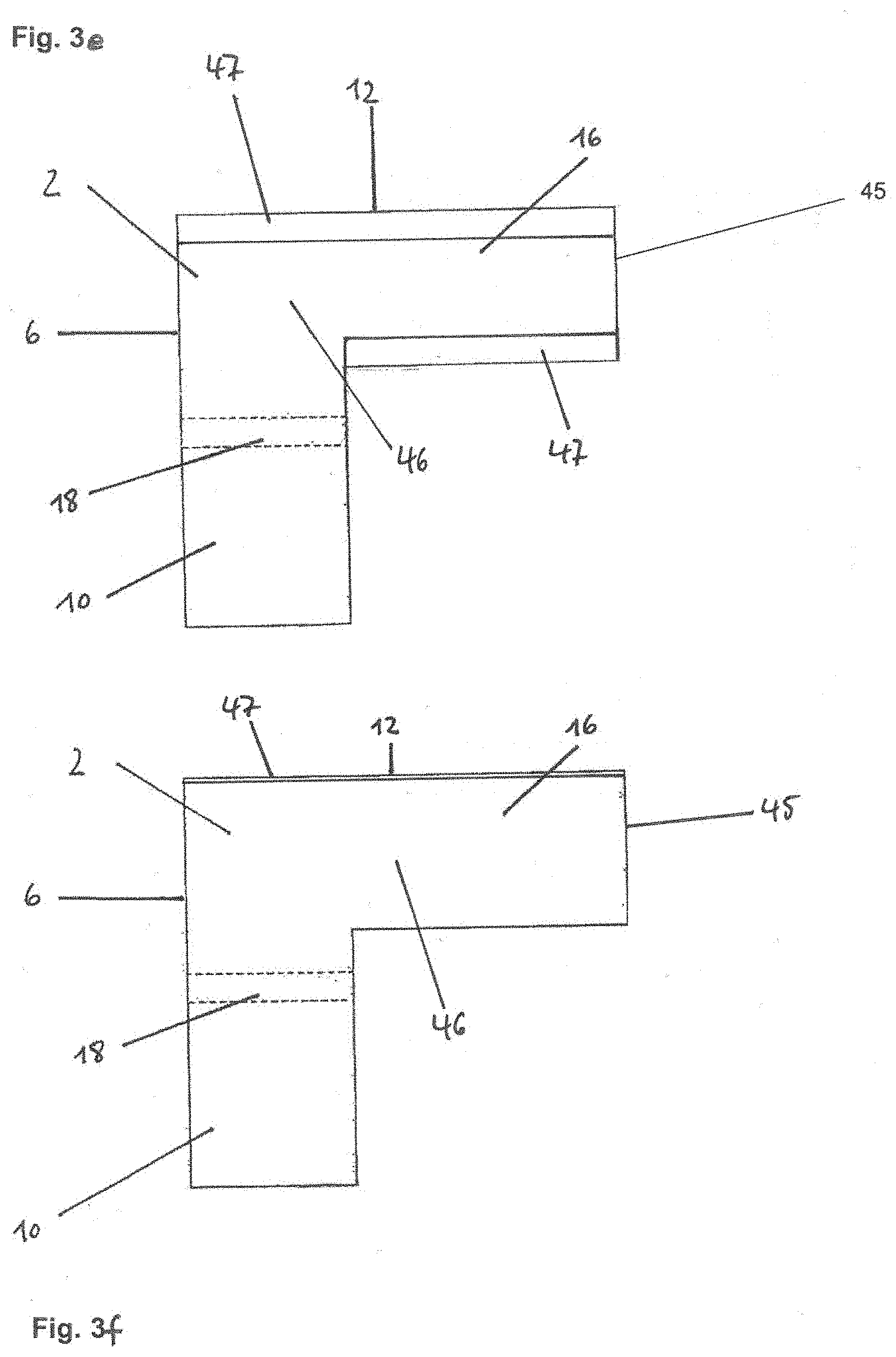
[0090] The support element 2 of FIG. 3e corresponds to the support element of FIG. 3c with the difference that an additional layer 47 with intumescent material is arranged on the side facing away from the second side surface 12.
[0091] The support element 2 of FIG. 3f corresponds to the support element of FIG. 3c with the difference that the layer 47 with intumescent material is thinner; it preferably has a thickness of between 0.25 mm and 10 mm, more preferably between 0.5 mm and 5 mm, even more preferably between 1 mm and 3 mm. If the intumescent material is expandable graphite, it preferably makes up 20-70%, more preferably 30-60% of the layer 47.
[0092] The strip-shaped layer 47 with intumescent material in FIG. 3f is fabric-like, film-like, or paper-like. The layer 47 in the original state is preferably in the form of a roll of material, which is unwound and adhered to the layer 46. In the embodiment according to FIG. 3f, it is guaranteed that, in the event of a fire, there will be an especially pronounced upward expansion of the intumescent material in the direction toward the window frame.
[0093] The support element 2 of FIG. 3g corresponds to the support element of FIG. 3f with the difference that the layer 47 with intumescent material is arranged on the third side surface 45, i.e., the side surface facing away from the first side surface 6. Otherwise, the same parameters as those described for FIG. 3f apply to the layer 47 also. In this embodiment, it is guaranteed that, in the event of a fire, there will be an especially pronounced expansion of the intumescent material toward the side (toward the right in the figure) in the direction of the outer wall.
[0094] The support element 2 of FIG. 3h corresponds to the support element of FIG. 3f with the difference that the layer 47 with intumescent material covers only part of the second side surface 12.
[0095] The layer 47 of the embodiment of FIG. 3d can also be combined with the layers 47 of the embodiment of FIG. 3c or 3e. The thin layer 47 of the embodiment of FIG. 3g can also be combined with the thin layer 47 of the embodiment of FIG. 3f or 3h. In addition, various thin layers 47 with various thicknesses of the layer 47 can be combined. For example, the thin layer 47 of FIG. 3g can be combined with the thick layer 47 of FIG. 3c.
[0096] In principle, all of the side surfaces or any desired selection of side surfaces can be completely or partially covered by a layer 47 with intumescent material.
[0097] The geometries of the support element 2 described on the basis of FIG. 3b can also be used in all of these embodiments.
[0098] In all of the previously described variants, one or more layers 47 can also extend over only a part of the associated side surface.
PRODUCTION EXAMPLES
Example 1A: Support Element with Waterglass
[0099] Inert sodium or potassium silicate (10-20%) is mixed to form a homogeneous mass with the base material, e.g., a rigid PUR foam or a rigid PUR/PIR foam, and optionally with one or more additives such as a curing agent. The mixture is pressed in a mold and cured by heat. Panels can be cut and processed into strip-shaped support elements.
Example 1B: Support Element with Expandable Graphite
[0100] Rigid PUR and/or PIR foam which originates from production residues and/or recycled material, e.g., old insulating panels, and which has been ground to a maximum particle size of approximately 5 mm, preferably of approximately 1 mm, is mixed with 5-10%, preferably 7.5%, of expandable graphite (average particle size, approximately 1 mm) and binder material, e.g., in liquid form, in a ratio of 1:5, calculated on the basis of the weight of the ground rigid foam. The mixture is introduced into a panel mold and treated by heat and pressure in a pressing direction P perpendicular to the surface of the panels, so that a rigid foam material with a bulk density of approximately 550 kg/m.sup.3 is obtained. The thickness of the panels is preferably 2-7 cm.
[0101] Alternatively, comminuted rigid foam pieces, expandable graphite flakes, and binder material can be introduced layer by layer in alternation (e.g., by interspersing) and then pressed.
[0102] Cured panels resulting from the pressing operation are cut into strip-shaped parts, and L-shaped support elements 2 according to FIG. 3a are produced by bonding a wider and a narrower element together, wherein, for both elements, the pressing direction P is preferably perpendicular to the second surface 12, which is intended to rest against the window frame 24 (see FIG. 1). The bonding is achieved by the use of an adhesive and/or by mechanical fastening with nails, screws, or metal clamps.
Example 1C: Support Element with an Expandable Graphite-Containing Layer
[0103] In the alternative embodiment shown in FIG. 3c, the upper layer 47 of the produced panel (i.e., a surface perpendicular to the pressing direction P) has a thickness of at least 10 mm, preferably of 15 mm, and has been combined with expandable graphite, wherein the remainder of the support element has not been combined with expandable graphite.
[0104] The strip-shaped support elements are produced as described in Example 1B.
Fire Tests
[0105] According to the test criteria of DIN 1366-5, support elements 2 of rigid PUR/PIR foam with expandable graphite, produced according to Example 1B with a thickness of 30 mm or 50 mm, were exposed to flames at 180.degree. C. (see test layout in FIG. 5d), during which procedure the increase in temperature was measured on the opposite side after 5, 15, and 25 minutes in comparison to corresponding rigid foam without expandable graphite.
[0106] On the side facing away from the flames, the temperatures were measured directly on the material after 5, 15, and 25 minutes for experimental applications on a ceiling (Tables 1-4) and a wall (Tables 5-6). The measured temperature increases (in degrees Kelvin; starting temperature, 23.degree. C.) are reproduced in the following tables (Tables 1, 3, 5: measurement on surface of the elements; Tables 2, 4, 6: measurement at the butt joint).
Ceiling
TABLE-US-00001 [0107] TABLE 1 30 mm, surface. test site material without expandable graphite material with expandable graphite 3.29 4.03 4.10 4.14 3.01 3.07 3.08 3.14 5 min 1 0 1 0 1 1 1 7 15 min 15 23 26 2 22 21 24 29 25 min 52 52 52 20 43 43 48 53
TABLE-US-00002 TABLE 2 30 mm, butt joint. no graphite with graphite test site 3.32 4.07 3.04 3.11 5 min 4 2 2 10 15 min 30 32 17 35 25 min 117 158 45 56
TABLE-US-00003 TABLE 3 50 mm, surface. test site material without expandable graphite material with expandable graphite 4.11 4.17 4.18 4.24 3.15 3.21 3.22 3.28 5 min 0 0 0 0 0 0 3 3 15 min 1 3 2 2 2 3 4 4 25 min 11 11 17 11 9 9 12 12
TABLE-US-00004 TABLE 4 50 mm, butt joint. no graphite with graphite test site 4.14 4.21 3.18 3.25 5 min 1 2 0 3 15 min 2 4 3 4 25 min 20 18 12 12
Wall:
TABLE-US-00005 [0108] TABLE 5 30 mm, surface. test site material without expandable graphite material with expandable graphite 1.15 1.21 1.22 1.28 1.29 7.07 7.08 7.14 5 min 8 0 5 1 8 1 8 5 15 min 19 22 30 20 33 25 30 30 25 min 57 50 52 49 57 44 49 50
TABLE-US-00006 TABLE 6 30 mm, butt joint. no graphite with graphite test site 1.18 1.25 1.32 7.11 5 min 2 1 2 3 15 min 30 22 30 25 25 min 80 67 50 45
[0109] Through the use of expandable graphite in the support elements 2 used both on ceilings and walls, the increase in temperature, especially at the butt joints, is considerably reduced. Thus, in the case of the rigid foam on the ceiling without expandable graphite, the temperature in the joint increased by, on average, 137.5.degree. C. after 25 minutes; in the case of material with expandable graphite, it increased by only 50.5.degree. C. on average. On the wall, the temperature of the rigid foam without expandable graphite increased in the joint by 73.5.degree. C. on average; and in the case of the material with expandable graphite, it increased by only 47.5.degree. C. on average. The increase in temperature, especially at the joints, was therefore significantly reduced by the use of support elements with expandable graphite.
[0110] FIGS. 4a and 4b show support elements with homogeneously distributed expandable graphite with an original thickness of 3 cm after exposure to flame on one side for 30 minutes (at the top in the figure). A graphite layer approximately 8 cm thick developed from 1 cm of material used.
[0111] FIGS. 5a-5c show top views of the flame-exposed side of support elements with homogeneously distributed expandable graphite with an expanded graphite layer on the flame-exposed side. In FIGS. 5a-5c, the arrows indicate the butt joints between adjacent components. FIG. 5d shows the layout of the flame exposure experiment. In FIG. 5d, the arrows indicate the direction of the flames in the various experiments. Depending on the arrangement (compare FIG. 5d, schematic diagram in the cross-sectional plane), the expanded graphite layer projects clearly beyond the plane of the concrete elements between the support elements, whereas the element, prior to exposure to flame, is on the same level with them (see especially FIG. 5b).
[0112] On the left, FIG. 6a shows part of a 30-mm-thick support element partially sawn through after 30 minutes of exposure to flame; the pressing direction P, indicated by the arrow, extends horizontally. The expansion in the direction of the pressing direction P is approximately twice as great (about 8 cm) as the expansion on the side perpendicular to the pressing direction, here the flame-exposed side on the right (approximately 4 cm). FIG. 6b shows the test piece after rotation by 90.degree.. It was thus determined that the expansion of the intumescent material on a surface perpendicular to the pressing direction P leads to greater expansion in the event of a fire than on a surface parallel to the pressing direction P.
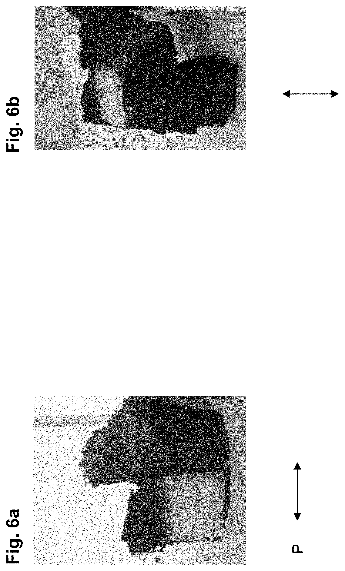
* * * * *
D00000
D00001
D00002
D00003
D00004
D00005
D00006
D00007
D00008
D00009
XML
uspto.report is an independent third-party trademark research tool that is not affiliated, endorsed, or sponsored by the United States Patent and Trademark Office (USPTO) or any other governmental organization. The information provided by uspto.report is based on publicly available data at the time of writing and is intended for informational purposes only.
While we strive to provide accurate and up-to-date information, we do not guarantee the accuracy, completeness, reliability, or suitability of the information displayed on this site. The use of this site is at your own risk. Any reliance you place on such information is therefore strictly at your own risk.
All official trademark data, including owner information, should be verified by visiting the official USPTO website at www.uspto.gov. This site is not intended to replace professional legal advice and should not be used as a substitute for consulting with a legal professional who is knowledgeable about trademark law.