Oven Uptakes
QUANCI; John Francis ; et al.
U.S. patent application number 16/729053 was filed with the patent office on 2020-07-02 for oven uptakes. The applicant listed for this patent is SUNCOKE TECHNOLOGY AND DEVELOPMENT LLC. Invention is credited to John Francis QUANCI, Gary Dean WEST.
| Application Number | 20200208059 16/729053 |
| Document ID | / |
| Family ID | 71123878 |
| Filed Date | 2020-07-02 |
View All Diagrams
| United States Patent Application | 20200208059 |
| Kind Code | A1 |
| QUANCI; John Francis ; et al. | July 2, 2020 |
OVEN UPTAKES
Abstract
Systems and apparatuses for controlling oven draft within a coke oven. A representative system includes an uptake damper coupled to an uptake duct that receives exhaust gases from the coke oven and provides the exhaust gases to a common tunnel for further processing. The uptake damper includes a damper plate pivotably coupled to a refractory surface of the uptake duct and an actuator assembly coupled to the damper plate. The damper plate is positioned completely within the uptake duct and the actuator assembly moves the damper plate between a plurality of different configurations by causing the damper plate to rotate relative to the uptake duct. Moving the uptake damper between the different configurations changes the flow rate and pressure of the exhaust gases through the uptake duct, which affects an oven draft within the coke oven.
| Inventors: | QUANCI; John Francis; (Haddonfield, NJ) ; WEST; Gary Dean; (Haddonfield, NJ) | ||||||||||
| Applicant: |
|
||||||||||
|---|---|---|---|---|---|---|---|---|---|---|---|
| Family ID: | 71123878 | ||||||||||
| Appl. No.: | 16/729053 | ||||||||||
| Filed: | December 27, 2019 |
Related U.S. Patent Documents
| Application Number | Filing Date | Patent Number | ||
|---|---|---|---|---|
| 62786027 | Dec 28, 2018 | |||
| Current U.S. Class: | 1/1 |
| Current CPC Class: | C10B 15/02 20130101; C10B 27/06 20130101; C10B 21/16 20130101; F16K 3/00 20130101 |
| International Class: | C10B 21/16 20060101 C10B021/16; C10B 27/06 20060101 C10B027/06 |
Claims
1. An uptake duct configured to receive exhaust gases, comprising: a channel through which the exhaust gases are configured to pass; a first refractory surface; a second refractory surface that opposes the first refractory surface, wherein the first and second refractory surfaces at least partially define the channel; a damper positioned entirely within the channel, wherein--the damper is movable between a plurality of orientations to change the flow of exhaust gases through the channel; and the damper remains entirely within the channel in each of the plurality of orientations.
2. The uptake duct of claim 1, wherein the damper is a damper plate having opposing first and second end portions, wherein-- the second end portion is spaced apart from the first refractory surface by a first distance when the damper plate is in a first of the plurality of orientations, and the second end portion is spaced apart from the first refractory surface by a second distance less than the first distance when the damper plate is in a second of the plurality of orientations.
3. The uptake duct of claim 2 wherein the damper plate has a plate surface that faces towards the first refractory surface and wherein, when the exhaust gasses pass over the plate surface, the plate surface has a substantially uniform temperature.
4. The uptake duct of claim 2 wherein the damper plate forms a first acute angle with the second refractory surface when the uptake damper is in the first orientation and a second acute angle greater than the first acute angle when the uptake damper is in the second orientation.
5. The uptake duct of claim 2, wherein the damper plate comprises a support layer and a facing layer, wherein the facing layer is made from a ceramic or refractory material.
6. An exhaust gas system for a coke oven, comprising: an uptake duct fluidly coupled to an oven chamber, wherein the uptake duct comprises opposing first and second refractory surfaces; and a damper plate positioned within the uptake duct and having opposing first and second end portions, wherein-- the first end portion is pivotably coupled to the second refractory surface, the damper plate is engaged by an actuator to be movable between a first position and a second position, and all of the damper plate is positioned within the uptake duct in both the first position and the second position.
7. The exhaust system of claim 6 wherein the damper plate has a first plate surface that faces generally toward the first refractory surface and a second plate surface that faces generally toward the second refractory surface.
8. The exhaust gas system of claim 7 wherein the first position comprises a completely-open position and the second position comprises a closed position and wherein the second end portion is positioned adjacent to the first refractory surface when the damper plate is in the closed position and positioned adjacent to the second refractory surface when the damper plate is in the completely-open position.
9. The exhaust system of claim 8 wherein the first plate surface is substantially parallel to the second refractory surface when the damper plate is in the completely-open position.
10. The exhaust gas system of claim 8 wherein the uptake duct includes a cavity formed in the second refractory surface and wherein, when the damper plate is in the completely-open position, the damper plate is received within the cavity.
11. The exhaust gas system of claim 10 wherein, when the damper plate is in the completely-open position and received within the cavity, the first plate surface is coplanar with the second refractory surface and the second plate surface is below the second refractory surface.
12. The exhaust gas system of claim 6, further comprising: an opening in the uptake duct that extends through a wall of the uptake duct; a rod contacting the second end portion and that passes through the opening such that a first portion of the rod is positioned within the uptake duct and a second portion is positioned outside of the uptake duct; and an actuator coupled to the control rod, wherein the actuator is configured to adjust the position of the damper plate by using the control rod to move the second end portion of the damper plate so that the damper plate rotates about the first end portion.
13. A coke oven, comprising: an oven chamber; an uptake duct in fluid communication with the oven chamber, wherein the uptake duct is configured to receive exhaust gases from the oven chamber; and an uptake damper system configured to control an oven draft, wherein-- the uptake damper system comprises a damper positioned entirely within the uptake duct and an actuator coupled to the damper, and the actuator is configured to control the oven draft by moving the damper to a selected one of a plurality of orientations, the damper remaining entirely within the uptake duct in each of the plurality of the orientations.
14. The coke oven of claim 13, wherein-- the damper is a damper plate comprising opposing first and second end portions, the damper plate is movable between the plurality of orientations by pivoting about the first end portion, and the actuator is coupled to the second end portion of the damper plate.
15. The coke oven of claim 14 wherein-- the actuator is positioned outside of the uptake duct, the uptake duct includes an opening that extends through the refractory surface, and the actuator couples to the second end portion of the damper plate through the opening.
16. The coke oven of claim 15, further comprising: a rod coupled between the actuator and the second end portion and that extends through the openings, wherein the actuator is configured to use the rod to move the damper plate the selected orientation.
17. The coke oven of claim 13 wherein the refractory surface is formed on a bottom wall of the uptake duct.
18. The coke oven of claim 13 wherein the refractory surface is formed on a sidewall of the uptake duct.
19. The coke oven of claim 13, wherein the uptake damper system is configured to operate at temperatures greater than 500.degree. F.
20. A method of operating a coke oven having an uptake duct in fluid communication with an oven chamber and configured to receive exhaust gases from the oven chamber, the method comprising: positioning an uptake damper within the uptake duct at a first configuration, wherein the uptake damper is positioned entirely within the uptake duct, and with an actuator, moving the uptake damper to a second configuration to thereby change an oven draft, wherein the uptake damper remains positioned entirely within the uptake duct in both the first configuration and the second configuration.
21. The method of claim 20, wherein-- the uptake damper is a damper plate including opposing first and second end portions, and the second end portion is spaced apart from the refractory surface of the uptake damper by a first distance when the uptake damper is in the first configuration and a second distance greater than the first distance when the uptake damper is in the second configuration.
22. The method of claim 20 wherein the oven draft is greater when the uptake damper is in the first configuration than when the uptake damper is in the second configuration.
23. The method of claim 20 wherein the uptake damper also includes a rod between the actuator and the second end portion of the damper plate and wherein the actuator is configured to use the rod to move the uptake damper to the selected configuration.
24. The method of claim 20 wherein the damper plate forms a first angle with the refractory surface when the uptake damper is in the first configuration and a second angle greater than the first angle when the uptake damper is in the second configuration.
25. An uptake duct configured to receive exhaust gases, comprising: a channel through which the exhaust gases are configured to pass; a first refractory surface; a second refractory surface that opposes the first refractory surface, wherein the first and second refractory surfaces at least partially define the channel, and wherein the uptake duct includes an opening that extends through the first refractory surface; and an uptake damper block system configured to control an oven draft, comprising: a damper block; and an actuator configured to vertically raise and lower the damper block into and out of the channel, wherein at least a portion of the uptake damper block system extends through the opening.
26. The uptake duct of claim 25, wherein the uptake damper block system further comprises at least one rod, the at least one rod contacting the damper block and configured to be raised and lowered by the actuator to thereby raise and lower the damper block into and out of the channel.
27. The uptake duct of claim 26, wherein the uptake damper block system further comprises a seal extending around the damper block proximate the opening to inhibit loss of heat, gas or both through the opening.
28. The uptake duct of claim 27, wherein the seal is mechanically actuable.
29. The uptake duct of claim 25, wherein the damper block comprises two or more damper blocks vertically staked on top of each other.
30. The uptake duct of claim 26, wherein the at least one rod is positively connected to the damper block.
31. The uptake duct of claim 25, wherein the damper block comprises a metal box and a block disposed on top of the metal box.
32. The uptake duct of claim 31, wherein the metal box is positively connected to the block.
33. The uptake duct of claim 31, wherein the uptake damper block system further comprises at least one rod, the at least one rod contacting the metal box and configured to be raised and lowered by the actuator to thereby raise and lower the damper block into and out of the channel.
34. The uptake duct of claim 31, wherein the uptake duct system is configured such that the metal box is incapable of entering the channel.
35. The uptake duct of claim 33, wherein the metal box includes a recess into which the rod extends.
36. The uptake duct of claim 35, wherein the rod is positively coupled to the metal box.
37. The uptake duct of claim 31, wherein the block comprises refractory material.
38. The uptake duct of claim 31, wherein the block comprises fiberboard.
39. An exhaust gas system comprising: a first channel through which exhaust gas is configured to pass, the first channel having a first longitudinal axis; a second channel through which exhaust gas is configured to pass, the second channel having a second longitudinal axis, wherein the second channel is in fluid communication with the first channel and is oriented relative to the first channel such that the first longitudinal axis and the second longitudinal axis form an angle greater than 0.degree.; and a damper system comprising a rotatable cylinder disposed in the first channel proximate a junction between the first channel and the second channel, the rotatable cylinder having a passage extending through the diameter of the rotatable cylinder, wherein the rotatable cylinder is configured to be rotated such that the passage is oriented to change the direction of exhaust gas flowing through the rotatable cylinder.
40. The exhaust gas system of claim 39, wherein the passage is an unobstructed passage.
41. The exhaust gas system of claim 39, wherein the damper system further comprises a rod attached to a top surface or bottom surface of the rotatable cylinder, the rod being configured to rotate the rotatable cylinder.
42. The exhaust gas system of claim 39, wherein the height of the rotatable cylinder is approximately equal to the height of the first channel and the diameter of the rotatable cylinder is approximately equal to the width of the first channel.
43. The exhaust gas system of claim 39, wherein the first longitudinal axis and the second longitudinal axis form an approximately 90 degree angle.
44. The exhaust gas system of claim 39, wherein the damper system further comprises one or more partitions formed within the passage.
45. The exhaust gas system of claim 39, wherein the rotatable cylinder is configured such that the rotatable cylinder can be rotated to a position where the passage is aligned approximately orthogonal to the first longitudinal axis such that exhaust gas flowing through the first channel cannot enter the passage.
46. The exhaust gas system of claim 39, wherein the first channel is an uptake duct and the second channel is a common tunnel.
47. An exhaust gas system, comprising: a first channel through which exhaust gas is configured to pass, the first channel having a first longitudinal axis; a second channel through which exhaust gas is configured to pass, the second channel having a second longitudinal axis, wherein the second channel is in fluid communication with the first channel and is oriented relative to the first channel such that the first longitudinal axis and the second longitudinal axis form an angle greater than 0.degree.; and a damper system disposed in the first channel proximate a junction between the first channel and the second channel, the damper system comprising: a first rotatable cylinder having a hollow interior, the first rotatable cylinder comprising a side wall, a first opening in the side wall, and a second opening in the side wall opposite the first opening; and a second rotatable cylinder disposed within the hollow interior of the first rotatable cylinder, the second rotatable cylinder comprising one or more vertically-oriented partitions forming channels extending through the width of the second rotatable cylinder, wherein the first rotatable cylinder and the second rotatable cylinder are independently rotatable.
48. The exhaust gas system of claim 47, wherein the height of the first rotatable cylinder and the second rotatable cylinder is approximately equal to the height of the first channel and the outer diameter of the first rotatable cylinder is approximately equal to the width of the first channel.
49. The exhaust gas system of claim 47, wherein the first rotatable cylinder is configured to be rotatable to a position where the sidewall blocks the passage of exhaust gas into the second rotatable cylinder.
50. The exhaust gas system of claim 47, wherein the vertically oriented partitions are straight wall partitions.
51. The exhaust gas system of claim 47, wherein the vertically oriented partitions are curved wall partitions.
52. The exhaust gas system of claim 47, wherein the second rotatable cylinder is configured such that the second rotatable cylinder can be rotated to a position where the vertically oriented partitions are oriented to change the direction of exhaust gas flowing through the second rotatable cylinder.
53. The exhaust gas system of claim 47, wherein the first longitudinal axis and the second longitudinal axis form an approximately 90 degree angle.
54. The exhaust gas system of claim 47, wherein the first channel is an uptake duct and the second channel is a common tunnel.
Description
CROSS-REFERENCE TO RELATED APPLICATION(S)
[0001] This non-provisional patent application claims the benefit of and priority to U.S. Provisional Patent Application No. 62/786,027, title "OVEN UPTAKES" and filed Dec. 28, 2018, which is incorporated by reference herein in its entirety by reference thereto.
TECHNICAL FIELD
[0002] The present technology relates to coke ovens and in particular to systems for regulating oven draft within the coke oven to control the coking process.
BACKGROUND
[0003] Coke is a solid carbon fuel and carbon source used to melt and reduce iron ore in the production of steel. Coking ovens have been used for many years to convert coal into metallurgical coke. In one process, known as the "Thompson Coking Process," coke is produced by batch feeding pulverized coal to an oven that is sealed and heated to very high temperatures for 24 to 48 hours under closely-controlled atmospheric conditions. During the coking process, the finely crushed coal devolatilizes and forms a fused mass of coke having a predetermined porosity and strength. Because the production of coke is a batch process, multiple coke ovens are operated simultaneously. To ensure that the coking rate is consistent throughout all of the ovens in a plant and to ensure that the quality of coke remains consistent between batches, the operating conditions of the coke ovens are closely monitored and controlled.
[0004] One operating condition for the coke ovens that is of particular importance is the oven draft within the coke ovens. During operation of the coke oven, fresh air from outside of the coke oven is drawn into the chamber to facilitate the coking process. The mass of coal emits hot exhaust gases (i.e. flue gas) as it bakes, and these gases are drawn into a network of ducts fluidly connected to the oven chamber. The ducts carry the exhaust gas to a sole flue below the oven chamber and the high temperatures within the sole flue cause the exhaust gas to combust and emit heat that help to further the coking reaction within the chamber. The com busted exhaust gases are then drawn out of the sole flue and are directed into a common tunnel, which transports the gases downstream for further processing.
[0005] However, allowing the exhaust gases to freely flow out into the common tunnel can reduce the quality of the coke produced within the oven. To regulate and control the flow of exhaust gases, coke ovens typically include dampers positioned between the sole flue and the common tunnel. These dampers typically include ceramic blocks that are moved into and out of the duct carrying the exhaust gases to adjust the flow rate and pressure of the exhaust gases. However, these ceramic blocks are often simultaneously exposed to the high-temperature exhaust gases within the ducts and room-temperature air outside of the ducts, resulting in the blocks being unevenly heated and leading to the formation of large temperature gradients within the blocks. This can cause the individual blocks to expand and contract unevenly, which can cause internal stresses within the ceramic material that causes the blocks to crack and fail. Additionally, this uneven heating and cooling makes the blocks more prone to ash deposition, which can cause the blocks to become fouled and plugged and can impede the operation of the blocks. Conventional dampers have large sections of the damper blocks located outside the gas path and outside the uptake itself. This leads to large cross section of block outside of the system and a large area for potential of air in leakage. Air in leakage impedes the performance of the system by leading to higher mass flows that lead to higher draft loss and reduction of draft to the ovens. In the case of heat recovery ovens this also leads to the reduction of power that can be recovered from the hot flue gas. Accordingly, there is a need for an improved damper system that is not prone to failing due to cracks caused by large thermal gradients.
BRIEF DESCRIPTION OF THE DRAWINGS
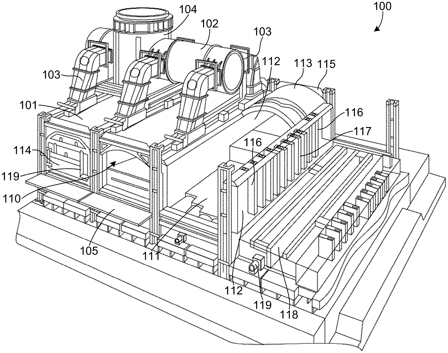
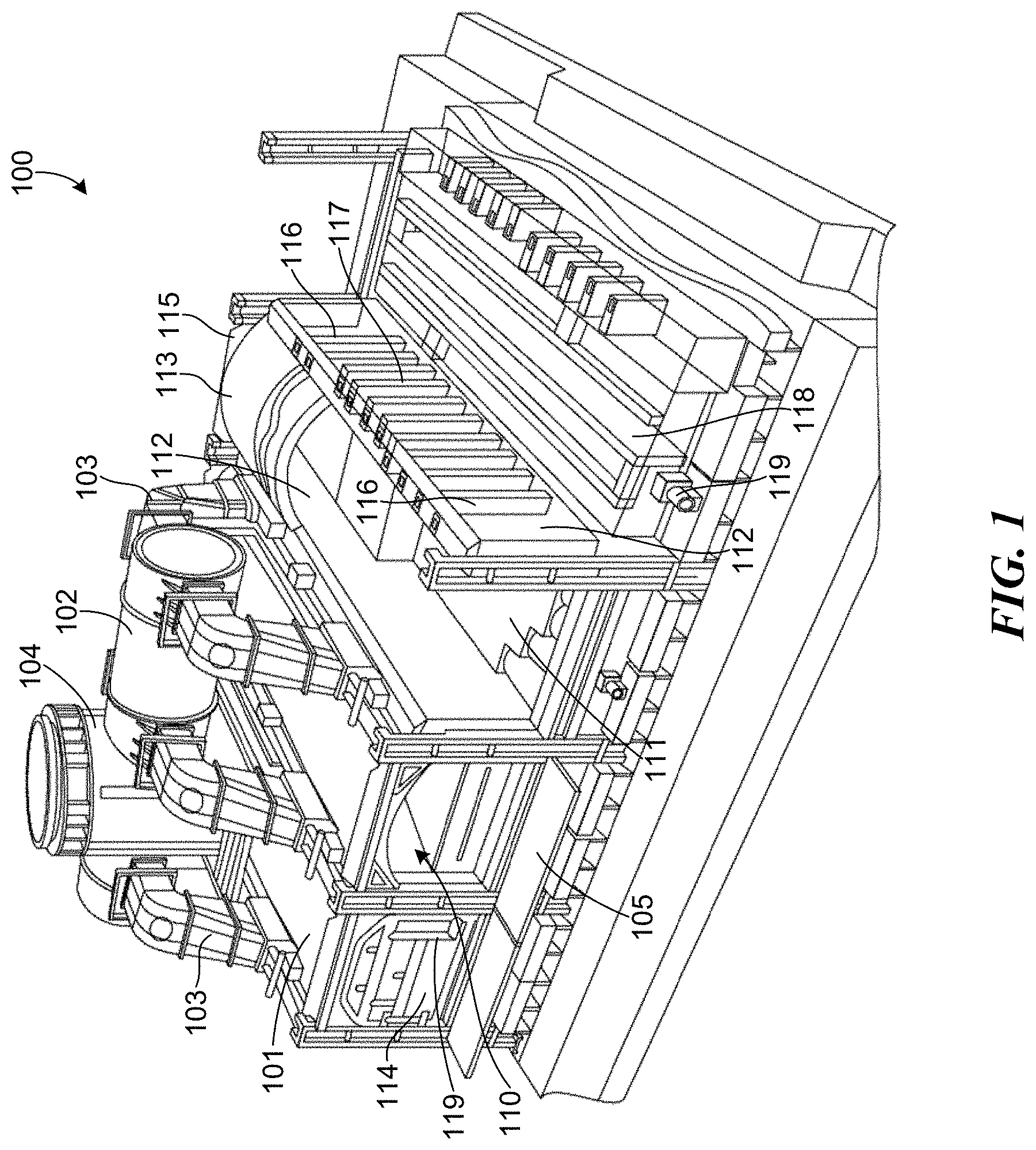
[0006] FIG. 1 is an isometric, partial cut-away view of a portion of a horizontal heat recovery/non-recovery coke plant configured in accordance with embodiments of the present technology.
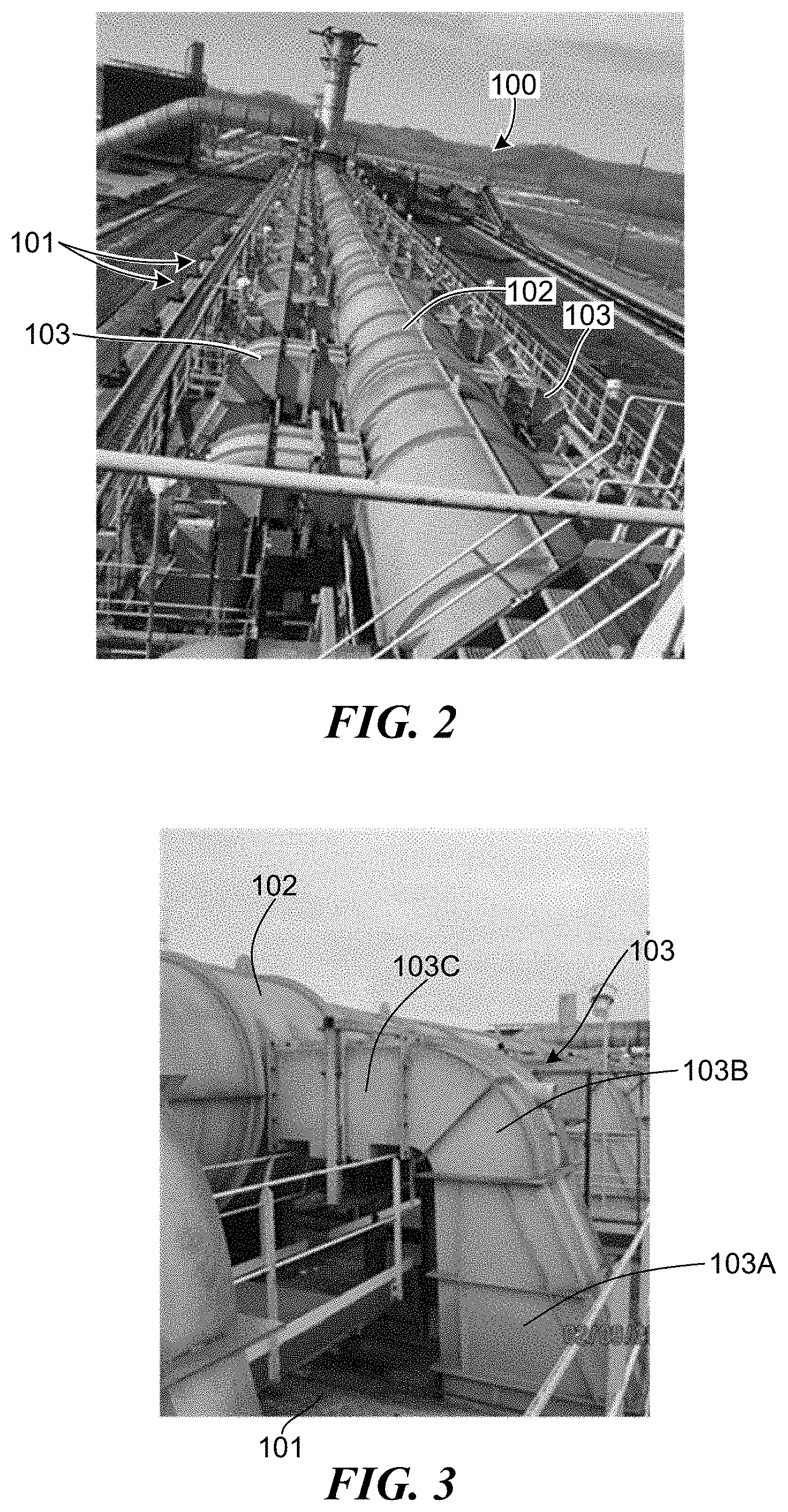
[0007] FIG. 2 is a perspective view of a common tunnel and a plurality of uptake ducts coupled to the common tunnel, in accordance with embodiments of the present technology.
[0008] FIG. 3 is an isometric view of one of the uptake ducts shown in FIG. 2.
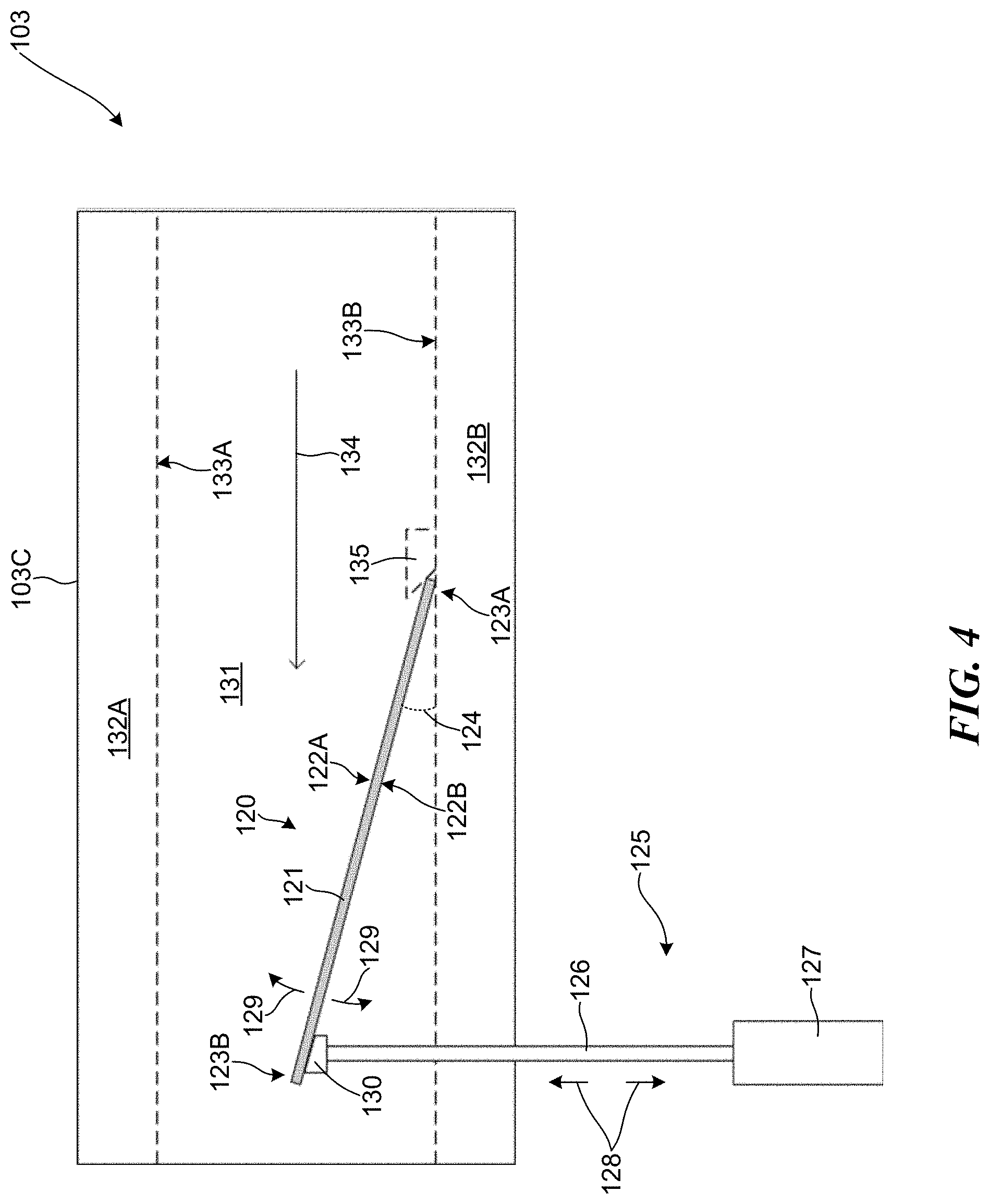
[0009] FIG. 4 is a diagram of an uptake damper system configured in accordance with embodiments of the present technology.
[0010] FIGS. 5 and 6 are front and rear isometric views of a damper plate positioned within an uptake duct, in accordance with embodiments of the present technology.
[0011] FIG. 7 shows a diagram of an alternative embodiment of the uptake damper system of FIG. 4, in accordance with embodiments of the present technology.
[0012] FIG. 8 shows a diagram of an alternative embodiment of the uptake damper system of FIG. 4, in accordance with embodiments of the present technology.
[0013] FIG. 9 shows a diagram of an alternative embodiment of the uptake damper system of FIG. 4, in accordance with embodiments of the present technology.
[0014] FIG. 10 shows a diagram of an alternative embodiment of the uptake damper system of FIG. 4, in accordance with embodiments of the present technology.
[0015] FIG. 11 shows a diagram of an alternative embodiment of the uptake damper system of FIG. 4, in accordance with embodiments of the present technology.
[0016] FIG. 12 shows a top diagram of two uptake dampers coupled between two uptake ducts and a common tunnel, in accordance with embodiments of the present technology.
[0017] FIGS. 13A-C show alternative embodiments of end portions of the damper plates shown in FIGS. 4-12, in accordance with embodiments of the present technology.
[0018] FIGS. 14A-B show an alternative to the uptake damper system shown in FIGS. 4-12, in accordance with embodiments of the present technology.
[0019] FIG. 15 shows an alternative to the uptake damper system shown in FIGS. 4-12, in accordance with embodiments of the present technology.
[0020] FIG. 16 shows an alternative to the uptake damper system shown in FIG. 15, in accordance with embodiments of the present technology.
[0021] FIGS. 16A and 16B are isometric views of a door provided on an uptake duct, in accordance with embodiments of the present technology.
[0022] FIG. 17 is an isometric view of a uptake damper in accordance with embodiments of the present technology.
[0023] FIGS. 18A and 18B are isometric views of an uptake damper in accordance with embodiments of the present technology.
[0024] FIGS. 19A-19D shows a top diagram of uptake damper systems in accordance with embodiments of the present technology.
DETAILED DESCRIPTION
[0025] Specific details of several embodiments of the disclosed technology are described below with reference to particular, representative configuration. The disclosed technology can be practiced in accordance with ovens, coke manufacturing facilities, and insulation and heat shielding structures having other suitable configurations. Specific details describing structures or processes that are well-known and often associated with coke ovens but that can unnecessarily obscure some significant aspects of the presently disclosed technology, are not set forth in the following description for clarity. Moreover, although the following disclosure sets forth some embodiments of the different aspects of the disclosed technology, some embodiments of the technology can have configurations and/or components different than those described in this section. As such, the present technology can include some embodiments with additional elements and/or without several of the elements described below with reference to FIGS. 1-19D.
[0026] Referring to FIG. 1, a coke plant 100 is illustrated which produces coke from coal in a reducing environment. In general, the coke plant 100 comprises at least one oven 101, along with heat recovery steam generators and an air quality control system (e.g. an exhaust or flue gas desulfurization system) both of which are positioned fluidly downstream from the ovens and both of which are fluidly connected to the ovens by suitable ducts. According to aspects of the disclosure, the coke plant can include a heat recovery or a non-heat recovery coke oven, or a horizontal heat recovery or horizontal non-recovery coke oven. The coke plant 100 preferably includes a plurality of ovens 101 and a common tunnel 102 that is fluidly connected to each of the ovens 101 with uptake ducts 103. A cooled gas duct transports the cooled gas from the heat recovery steam generators to the flue gas desulfurization system. Fluidly connected and further downstream are a baghouse for collecting particulates, at least one draft fan for controlling air pressure within the system, and a main gas stack for exhausting cooled, treated exhaust to the environment. Steam lines interconnect the heat recovery steam generators and a cogeneration plant so that the recovered heat can be utilized. The coke plant 100 can also be fluidly connected to a bypass exhaust stack 104 that can be used to vent hot exhaust gasses to the atmosphere in emergency situations.
[0027] FIG. 1 illustrates four ovens 101 with sections cut away for clarity. Each oven 101 comprises an oven chamber 110 preferably defined by a floor 111, a front door 114, a rear door 115 preferably opposite the front door 114, two sidewalls 112 extending upwardly from the floor 111 intermediate the front 114 and rear 115 doors, and a crown 113 which forms the top surface of the oven chamber 110. The oven 101 can also include a platform 105 adjacent to the front door 114 that a worker can stand and walk on to access the front door and the oven chamber 110. In operation, coke is produced in the ovens 101 by first loading coal into the oven chamber 110, heating the coal in an oxygen depleted environment, driving off the volatile fraction of coal and then oxidizing the volatiles within the oven 101 to capture and utilize the heat given off. The coal volatiles are oxidized within the ovens over a 48-hour coking cycle and release heat to regeneratively drive the carbonization of the coal to coke. The coking cycle begins when the front door 114 is opened and coal is charged onto the floor 111. The coal on the floor 111 is known as the coal bed. Heat from the oven (due to the previous coking cycle) starts the carbonization cycle. Preferably, no additional fuel other than that produced by the coking process is used. Roughly half of the total heat transfer to the coal bed is radiated down onto the top surface of the coal bed from the luminous flame and radiant oven crown 113. The remaining half of the heat is transferred to the coal bed by conduction from the floor 111 which is convectively heated from the volatilization of gases in sole flue 118. In this way, a carbonization process "wave" of plastic flow of the coal particles and formation of high strength cohesive coke proceeds from both the top and bottom boundaries of the coal bed at the same rate, preferably meeting at the center of the coal bed after about 45-48 hours.
[0028] In operation, volatile gases emitted from the coal positioned inside the oven chamber 110 collect in the crown 113 and are drawn downstream in the overall system into downcomer channels 117 formed in one or both sidewalls 112. The downcomer channels 117 fluidly connect the oven chamber 110 with the sole flue 118 positioned. The sole flue 118 forms a circuitous path beneath the floor 111 and volatile gases emitted from the coal can pass through the downcomer channels 117 and enter the sole flue 118, where they combust and emit heat that supports the reduction of coal into coke. Uptake channels 116 are formed in one or both sidewalls 112 of the oven chambers 110 and are fluidly coupled between the sole flue 118 and uptake ducts 103 such that the com busted volatile gases can leave the sole flue 118 by passing through the uptake channels 116 toward the uptake ducts 103. The uptake ducts 103 direct the volatile gases into the common tunnel 102, which transports these gases downstream for further processing.
[0029] Controlling air flow and pressure inside the oven 101 can be critical to the efficient operation of the coking cycle. Accordingly, the oven 101 includes multiple apparatuses configured to help regulate and control the oven draft within the oven 110. For example, in the illustrated embodiment, the oven 101 includes one or more air inlets 119 that allow air into the oven 101. Each air inlet 119 includes an air damper which can be positioned at any number of positions between fully open and fully closed to vary the amount of primary air flow into the oven 101. In the illustrated embodiment, the oven 101 includes an air inlet 119 coupled to the front door 114, which is configured to control air flow into the oven chamber 110, and an air inlet 119 coupled to a sole flue 118 positioned beneath the floor 111 of the oven 101. Alternatively, the one or more air inlets 119 are formed through the crown 113 and/or in uptake ducts 103. The air inlet 119 coupled to the sole flue 118 can fluidly connect the sole flue 118 to the atmosphere and can be used to control combustion within the sole flue.
[0030] FIG. 2 shows a perspective view of the coke plant 100 and FIG. 3 shows an isometric view of an uptake duct 103 fluidly coupled between the common tunnel 102 and one of the ovens 101. In the illustrated embodiment, each of the ovens 101 includes two uptake ducts 103 that fluidly couple the ovens 101 to the common tunnel 102. In other embodiments, each of the ovens 101 can be coupled to the common tunnel 102 with a single uptake duct 103 or can be coupled with more than two uptake ducts 103. Alternatively, in some embodiments, adjacent ovens 101 can share uptake ducts 103 such that a single uptake duct 103 can fluidly couple two ovens 101 to the common tunnel 102. In general, any suitable number of uptake ducts 103 can be used to fluidly couple the ovens 101 to the common tunnel 102.
[0031] Each of the uptake ducts 103 can have a generally bent configuration and can be formed from a vertical segment 103A, a bent segment 103B, and a horizontal segment 103C, where the bent segment 103B fluidly couples the vertical and horizontal segments 103A and 103C together. The vertical segment 103A, which can extend generally upward from a top surface of the oven 101, can receive exhaust gas from at least some of the uptake channels within a given one of the sidewalls and direct the gas toward the bent segment 103B. The horizontal segment 103C is coupled between the common tunnel 102 and the bent segment 103B and is positioned to receive the exhaust gas from the bent segment 103B and provide the gas to the common tunnel 102, which directs the gas downstream for further processing. In the illustrated embodiment, the horizontal segment 103C is coupled to the common tunnel 102 such that the horizontal segment 103C is generally orthogonal to the common tunnel 102. In other embodiments, however, the horizontal segment 103C can be coupled to the common tunnel 102 at an angle other than 90.degree..
[0032] While the one or more air inlets 119 can be used to control how much outside air can flow into the oven 101, the air inlets 119 may not be able to directly regulate the flow of exhaust gases leaving the oven 101 via the uptake channels 116 and uptake ducts 103. Accordingly, to control the flow of exhaust gas out of the oven 101 and oven draft/vacuum, the uptake ducts 103 can include uptake dampers configured to restrict the flow of exhaust gases out of the oven 101. Embodiments of the technology described herein generally relate to dampers and damper systems suitable for use in controlling the flow of exhaust gas and/or oven draft. In some embodiments, the damper is configured to more between a plurality of orientations to thereby change exhaust gas flow and/or oven draft. However, regardless of the orientation of the damper, the entire damper remains in the duct/channel. In some embodiments, the damper forms part of a damper system, which can include, e.g., the damper, valves, controllers, etc., and each component of the damper system remains in the duct/channel regardless of the orientation of the damper. The damper system can further include an actuator used to move the damper to different possible damper orientations. The actuator can be located within the duct/channel, outside the duct/channel, or partially inside and partially outside the duct channel (which includes embodiments where the actuator moves between being inside and outside of the duct/channel). In embodiments where the actuator is located within the duct/channel, the actuator may remain entirely within the duct/channel regardless of the orientation of the damper.
[0033] The damper of the damper system that is disposed within and remains within the duct/channel can be any suitable type of damper. As discussed in greater detail below, the damper can be, for example, a damper plate, a plurality of damper plates, a block, a plurality of blocks, a rotatable cylinder, or a plurality of rotatable cylinders. Other suitable dampers include valves, such as butterfly valves. Generally speaking, any structure that can alter the flow of exhaust gas via change in orientation within the channel/duct can be used as the damper.
[0034] FIG. 4 shows a diagram of an uptake damper 120 positioned within the horizontal segment 103C of the uptake duct 103 and configured in accordance with embodiments of the present technology. The horizontal segment 103C includes upper and lower walls 132A and 132B, where a first refractory surface 133A of the upper wall 132A and a second refractory surface 133B of the lower wall 132B at least partially define a channel 131. The channel 131 is fluidly coupled to the oven and exhaust gases received from the oven can move toward the common tunnel 102 by flowing in the direction shown by arrow 134. The uptake damper 120 includes a damper plate 121 having top and bottom surfaces 122A and 122B, where the damper plate 121 is positioned such that the top surface 122A faces generally toward the upper wall 132A while the bottom surface 122B faces generally toward the lower wall 1328. In the illustrated embodiments, the uptake duct 103 has a generally rectangular cross-section and the damper plate 121, accordingly, also has a rectangular shape. In other embodiments, however, the uptake duct 103 can have a generally circular cross-section and the damper plate 121 is sized and shaped to conform to the shape of uptake duct 103.
[0035] The damper plate 121 includes first and second end portions 123A and 123B, where the first end portion 123A is pivotably coupled to the second refractory surface 133B while the second end portion 123B is not coupled to the second refractory surface 133B. With this arrangement, the damper plate 121 can be moved to a selected orientation by moving the damper plate 121 in the directions shown by arrows 129 about the first end portion 123A until an angle 124 formed between the bottom surface 122B and the second refractory surface 133B reaches a selected angle. As the damper plate 121 moves between orientations, the distance between the second end portion 123B and the first refractory surface 133A changes. Accordingly, the uptake damper 120 can be movable between an infinite number of configurations by moving the damper plate to different orientations. In this way, the uptake damper 120 can be used to control and regulate the flow of gases moving through the channel 131, which can affect the oven draft within the oven 101, as the orientation of the damper plate 121 affects the ability of the gases within the channel 131 to flow past the uptake damper 120.
[0036] For example, the uptake damper 120 can be moved to a completely-open configuration in which the uptake damper 120 does not significantly affect the ability of the exhaust gases to flow through the channel 131 in the direction 134. In this configuration, the damper plate 121 is oriented such that the bottom surface 122B is positioned against the second refractory surface 133B, the angle 124 is approximately equal to 0.degree., and the distance between the second end portion 123B and the first refractory surface 133A is at a maximum. Conversely, the uptake damper 120 can also be moved to a closed configuration that significantly restricts the ability of the exhaust gases to flow through the channel 131. In this configuration, the damper plate 121 is oriented such that the second end portion 123B is positioned closely adjacent to the first refractory surface 133A and the angle 124 is at a maximum value that is greater than 0.degree.. Accordingly, when the uptake damper 120 is in the closed configuration, the damper plate 121 can cause the flow rate within the channel 131 to significantly decrease. As a result, the pressure within the channel 131 increases, which results in the pressure within the uptake channels 116, the sole flue 118, the downcomer channels 117, and the oven chamber 110 to also increase. In some embodiments, when the uptake damper 120 is in the closed configuration, the maximum value of the angle 124 can be approximately 45.degree.. In other embodiments, however, the maximum value of the angle 124 can be some other angle generally determined by the dimensions of the damper plate 121 and the distance between the first and second refractory surfaces 133A and 133B. To further increase the ability of the uptake damper 120 to seal-off the channel 131 when the uptake damper 120 is in the closed configuration, in some embodiments, the horizontal segment 103C can include a lip attached to the first refractory surface 133A and positioned such that the second end portion 123B is positioned against the lip. In this way, the lip can help to prevent exhaust gas from flowing between the second edge portion 123B and the first refractory surface 133A when the uptake damper 120 is in the closed configuration.
[0037] The uptake damper 120 can also be moved to any configuration between the completely-open and closed configurations. For example, when the uptake damper 120 is in the configuration shown in FIG. 4, the damper plate 121 is oriented such that the angle 124 is approximately 15.degree. and the second end portion 123B is located at roughly a midpoint between the first and second refractory surfaces 133A and 133B such that the distance between the second end portion 123B and the first refractory surface 133A is approximately equal to the distance between second end portion 123B and the second refractory surface 133B. Accordingly, when in this configuration, the amount of space for the exhaust gases to flow through, and therefore the flow rate of the exhaust gases within the channel 131, is less than when the uptake damper 120 is in the completely-open configuration but more than when the uptake damper 120 is in the closed configuration. As a result, the pressure within the channel 131, and therefore the pressure within the uptake channels 116, the sole flue 118, the downcomer channels 117, and the oven chamber 110, is greater than when the uptake damper 120 is in the completely-open configuration but less than when the uptake damper 120 is in the closed configuration. In this way, moving the uptake damper 120 to a selected configuration can allow the uptake damper to help control and regulate the oven draft within the oven chamber 110.
[0038] To cause the uptake damper 120 to move between the various configurations, the uptake damper 120 can include an actuator apparatus 125 configured to help move the damper plate 121 to a selected orientation. The actuator assembly 125 includes a rod 126 that contacts the bottom surface 122B of the damper plate 121 and an actuator 127 operatively coupled to the rod 126 such that the actuator 127 can move the rod 126 vertically up and down, as shown by arrows 128. The rod 126 can be straight or can be curved and can have a circular cross-section, a rectangular cross-section, or any other suitable shape. The actuator 127 is located outside of the uptake duct 103 while the rod 126 extends through an opening formed through the lower wall 132B and contacts the second end portion 123B with an contacting apparatus 130. In this way, when the actuator 127 moves the rod up and down, the rod 126 moves into and out of the channel 131 and moves the second end portion 123B up and down as well. As a result, the actuator assembly 125 can be used to move the damper plate 121 between different orientations by causing the second end portion 123B to move until the second end portion 132B is positioned at a selected position between the first and second refractory surfaces 133A and 133B and the angle 124 is at a selected value. In some embodiments, the contacting apparatus 130 or the rod 126 are coupled to the second end portion 123B of the damper plate 121. In such embodiments, the first end portion 123A is generally not coupled to any structure so that it may slide freely as the damper plate 121 is moved up or down. In one aspect of this embodiment, the damper plate 121 can include a groove formed in the bottom surface 122B that allows the rod 126 or contacting apparatus 130 to slide along the bottom surface 122B as the damper plate moves between orientations. When the rod 126 or contacting apparatus 130 are coupled with the damper plate 121, the actuator 125 can be configured to lift the damper plate, while relying on gravity to lower the damper plate 121, or the actuator 125 can be configured both lift and lower the damper plate 121. In alternate embodiments, the damper plate 121 can be resting on the rod 126 or contacting apparatus 130 without being actively coupled to the rod or contacting apparatus. In such an embodiment, the first end portion 123A may be pivotably coupled to, for example, the lower wall 132B, or a block 135 may be provided to prevent movement of the first end portion 123A of the damper plate 121 past a specific location.
[0039] In some embodiments the rod 126 and the opening in the lower wall 132B are angled with respect to the lower wall 132B to reduce the possibility of the rod 126 pinching against the lower wall 132B as it moves into and out of the opening. To reduce the amount of gas that can leak out of the uptake duct 103 by flowing through the opening in the lower wall 132B, the opening can be sized and shaped to be just slightly larger than the rod 126. In this way, leakage through the opening can be reduced. In some embodiments, insulation can be positioned around the opening to further reduce leakage of gas through the openings and to keep the rod 126 centered within the opening. In other embodiments, the size of the opening is small enough that additional insulation/sealing material is not necessary.
[0040] In some embodiments, the actuator 127 can be operated remotely and/or automatically. Further, in some embodiments, the actuator assembly 125 can include a linear position sensor, such as a Linear Variable Differential transformer, that can be used to determine the position of the rod 126, and therefore the orientation of the damper plate 121, and to provide the determined orientation to a central control system. In this way, the uptake damper 120 can be controlled and monitored remotely and a single operator can control the uptake dampers for each of the coke ovens 101 at a coke plant using a central control system. In other embodiments, other position sensors, such as radar can be used instead of, or in addition to the linear position sensor. In still other embodiments, the position sensor can be positioned inside of the actuator 127.
[0041] In alternate embodiments to the embodiments shown in FIG. 4, the damper plate 121 can be coupled to the second refractory surface 133B, including with the use of a different connection means than what is shown in FIG. 4. For example, in some embodiments, the damper plate can be coupled to the second refractory surface with a hinge apparatus or with a groove formed in the lower wall 132B.
[0042] Regardless of the specific damper type and/or the mechanism used to move the damper to a different orientation, the size of the components of the damper system other than the damper itself are preferably minimized to the greatest extent possible, especially with respect to components that are located within the duct/channel and/or enter into the duct/channel at any point during a change in damper orientation. Minimizing the size of these components can be preferable in order to have lower air in leakage and less cooling of the damper system in the flow path, which minimizes damper system damage and buildup of ash.
[0043] During operation of the coke oven 101, the exhaust gases received within the uptake duct 103 are typically in the range of 500.degree. F. to 2800.degree. F. Accordingly, care must be taken when constructing the uptake damper 120 to form the damper plate 121 from a material that retains its shape and structure at these elevated temperatures. In particular, the damper plate 121 can be formed from a refractory material, a ceramic (e.g., alumina, zirconia, silica, etc.), quartz, glass, steel, or stainless steel as long as the selected material holds and remains functional at high temperatures. The damper plate 121 can also include reinforcing material to increase the strength and durability of the damper plate 121. In some embodiments, the damper plate is made from or incorporates a material that is non-brittle at the operating temperatures of the coke oven. In some embodiments, the damper plate is a composite construction, such a damper plate having a base made of a first material and a layer affixed to the base that is made from a second material different from the first material. The layer affixed to the base may be on the face of the base that is contacted by gas and may be glued or otherwise affixed to the base. In an exemplary embodiment, the base is formed from a heavy material such as steel or a fused silica block, and the layer formed on the base is made from a lightweight fiber board or ceramic material. In this configuration, the damper plate has a preferred non-brittle material on the face of the damper plate that contacts the gas while also having sufficient weight and strength. If the damper plate gets stuck in a specific configuration, the embodiment in which a strong base material is provided allows a technician to aggressively handle the damper plate to dislodge the damper plate without damaging the damper plate. The composite damper plate as described above can be made of any number of layers, such as one or more base layers and/or one or more non-brittle layers. In other embodiments, the damper plate can be made entirely from the non-brittle material (i.e., with no underlying base material).
[0044] As shown in FIG. 4, the uptake damper 120 can be positioned within the uptake 103 such that the entire damper plate 121 is located within the channel 131 of the uptake duct 103. Thermal gradients within the damper plate 121 can sometimes cause different portions of the damper plate to expand and contract by different amounts and at different rates, which can sometimes lead to cracking of the damper plate. However, because the entire damper plate 121 is located within the channel 131, the entire damper plate 121 is subjected to similar temperatures, which results in the entire damper plate 121 being at a generally uniform temperature and any thermal gradients within the damper plate 121 being reduced. Accordingly, the configuration shown in FIG. 4 can reduce the likelihood of the damper plate cracking due to thermal gradients within the damper plate 121 and can also reduce the potential of ash/slag from building up on the uptake plate 121 since the uptake plate 121 is closer to the actual flue gas temperature.
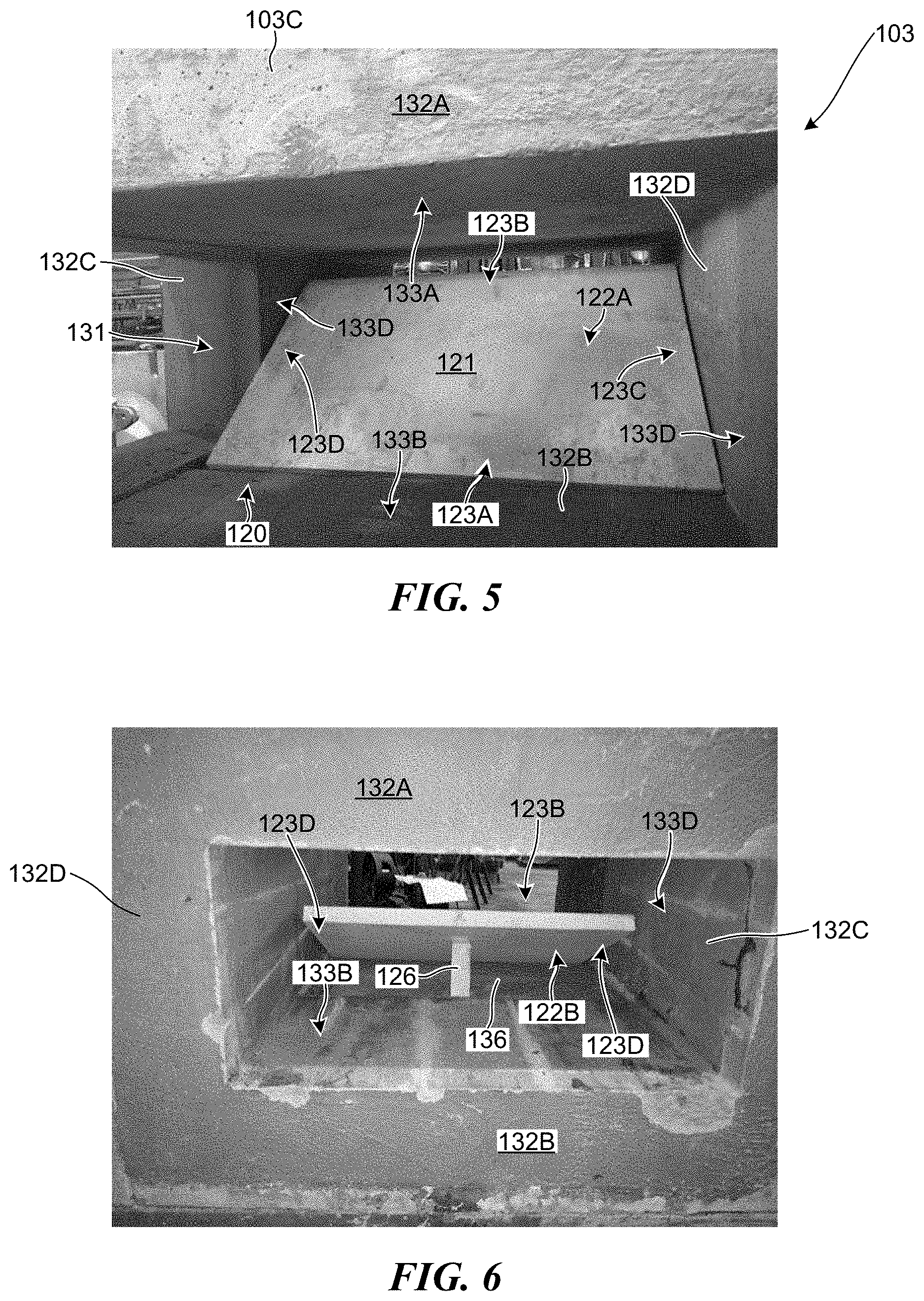
[0045] In the illustrated embodiment, the damper plate 121 is resting on the second refractory surface 133B such that, when the uptake damper 120 is in the completely-open configuration and the angle 124 has a value of approximately 0.degree., the bottom surface 122B is generally coplanar with the second refractory surface 133B and the top surface 122A is above the second refractory surface 133B. In other embodiments, however, the damper plate 121 can be positioned within the uptake duct 103 such that a portion of the damper plate 121 is below the second refractory surface 133B. For example, in the embodiment shown in FIGS. 5 and 6, the horizontal segment 103C of the uptake duct 103 includes a recess 136 formed in the lower wall 132B and the damper plate 121 is positioned such that the first end portion 123A is disposed within the recess 136 while the rod 126 can extend through an opening formed in the recess to couple to the bottom surface 122B of the damper plate 121. The recess 136 can have a size and shape similar to that of the damper plate 121 such that, when the uptake damper 120 is moved to the completely-open configuration, the damper plate 121 can move downward until both the first and second end portions 123A are positioned within the recess 136. Further, the recess can have a depth substantially equal to a thickness of the damper plate 121 such that, when the uptake damper 120 is in the completely-open configuration, the top surface 122A is generally coplanar with the second refractory surface 133B and the lower surface 122B is below the second refractory surface 133B.
[0046] As shown in FIG. 6, a single rod 126 is used raise and lower damper plate 121, with the width of the rod 126 being substantially smaller than the width of the damper plate 121. However, it should be appreciated that configurations can also be provided wherein multiple rods 126 are used to raise and lower the damper plate 121, and/or the width of the rod 126 is substantially larger, including approximately equal to the width of the damper plater 121.
[0047] As previously discussed, the damper plate 121 can be sized and shaped such that, when the uptake damper is in the closed configuration, the first and second end portions 123A and 123B can be positioned against the first and second refractory surfaces 133A and 133B. In this way, the damper plate 121 can be sized and shaped to extend between the upper and lower walls 132A and 132B. The damper plate 121 can also be sized and shaped to extend between first and second sidewalls 132C and 132D of the horizontal segment 103C. More specifically, the damper plate 121 has a generally-rectangular shape and can include third and fourth end portions 123C and 123D that are configured to be positioned adjacent to third and fourth refractory surfaces 133C and 133D of the first and second sidewalls 132C and 132D. In this way, when the uptake damper 120 is in the closed configuration, the damper plate 121 can extend across the entire width and height of the channel 131 and can therefore prevent all, or at least most, of the gas within the channel 131 from flowing past the uptake damper 120.
[0048] As shown in FIG. 5, the channel 131 can include an opening 137 located proximate the damper plate 121. In FIG. 5, the opening 137 is formed in first sidewall 132C. Opening 137 provides access to the damper plate 121 so that maintenance can be performed on the damper plate 121. With reference to FIGS. 16A and 16B, the opening 137 can include a door 138 that seals off the opening 137 when the uptake duct is in operation. In some embodiments, the door 138 is made from or incorporates lightweight refractory material. The door 138 can be hinged or slide in order to provide access to the damper plate 121, and may also include one or more handles 139 or the like on an external side of the door 138 for ease of opening and closing of the door 138. In some embodiments, a lightweight ceramic fiber 138b is filled in the opening 137 on the interior side of the door 138. The lightweight ceramic material 138b is easily removed from the opening 137 after the door 138 is opened to thereby provide access to the channel 131.
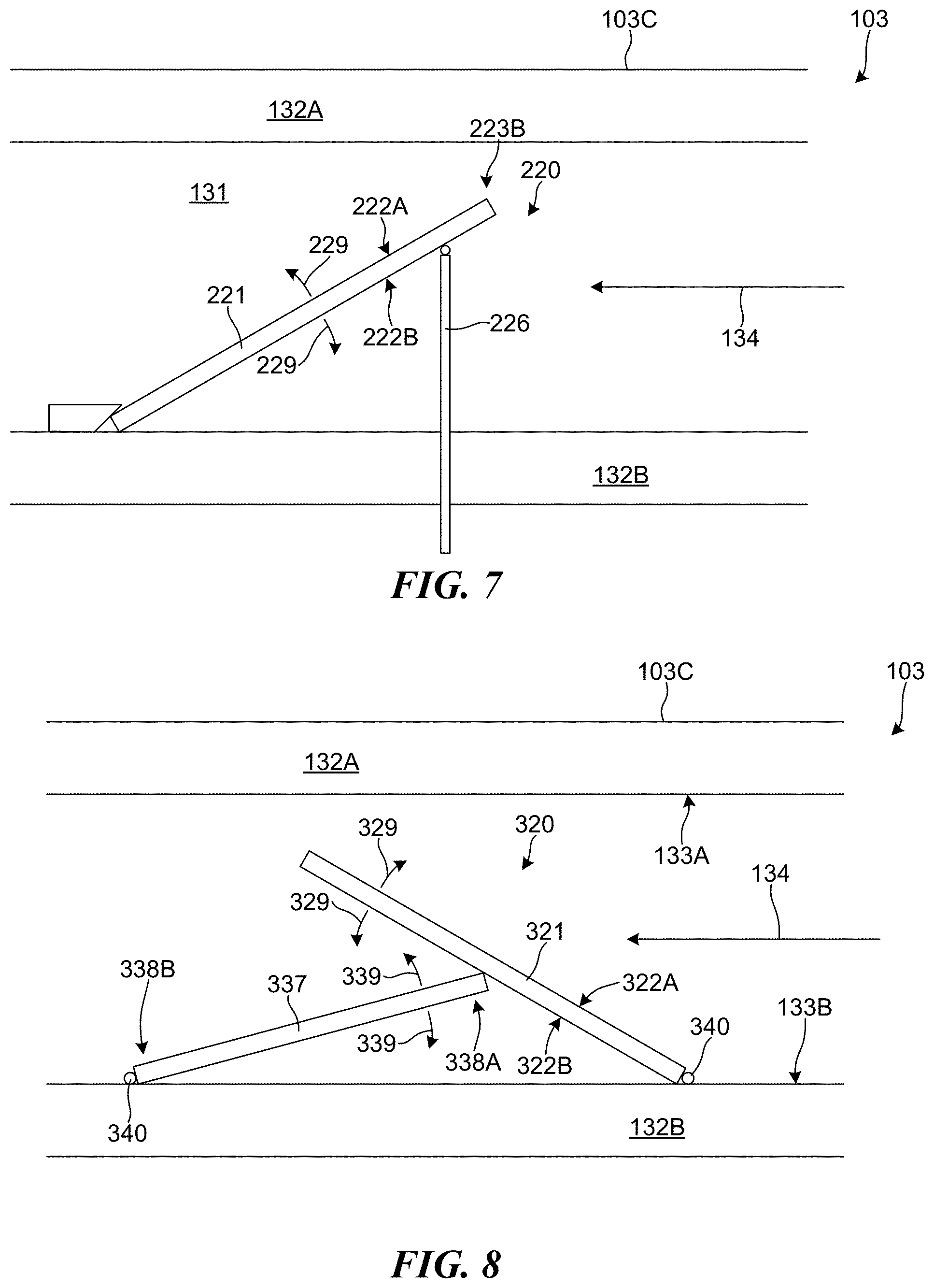
[0049] In the previously illustrated embodiments, the uptake damper 120 is positioned and oriented within the channel 131 such that the damper plate 121 is positioned on the second refractory surface 133B and is oriented such that the top surface 122A faces generally toward the exhaust gases flowing in the direction 134 while the bottom surface 122B faces generally away from the gases. In this way, the exhaust gases within the channel 131 tend to impact the top surface 122A and are directed over the second end portion 123B without interacting with the bottom surface 122B. In other embodiments, however, the uptake damper 120 can be differently positioned and oriented within the horizontal segment 103C. For example, FIG. 7 shows a diagram of an alternative implementation of the uptake damper 220. The uptake damper 220 is positioned within the horizontal segment 103C such that the bottom surface 222B of the damper plate 221 faces generally toward the gases flowing through the channel 131 in the direction 134 while the top surface 222A faces generally away from the gases. In this way, the exhaust gases within the channel 131 tend to impact bottom surface 222B and flow over the second end portion 223B without significantly interacting with the top surface 122A. Further, the rod 226 can be used to help move the uptake damper 220 between configurations by causing the damper plate 220 to move towards or away from the lower wall 132B, as shown by arrows 229. While FIG. 7 shows an embodiment where first end portion 223A is free moving (save for block 235 which prevents over-sliding of the damper plate 221) and rod 226 is coupled with second end portion 223B, it should be appreciated that the opposite configuration (first end portion 223A is fixed in place via, e.g., a hinge and second end portion 223B is free moving) can also be used.
[0050] FIG. 8 shows a diagram of an alternative embodiment of the uptake damper 320. The uptake damper 320 includes a damper plate 321 and a control plate 337. The damper plate 321 and the control plate 337 are both coupled to the second refractory surface 133B of the lower wall 132B and are positioned such that the bottom surface 322B of the damper plate 321 faces toward the control plate 337. A first end portion 338A of the control plate 337 is positioned against the bottom surface 322B of the damper plate 322A and a second end portion 338B of the control plate 337 is pivotably coupled to the second refractory surface 132B such that the control plate can be pivoted about the second end portion 338B, as shown by arrows 339. With this arrangement, pivoting the control plate 337 causes the first end portion 338A to slide along the bottom surface 322B of the damper plate 321, which can push the damper plate 321 into a different orientation. Accordingly, the control plate 337 can be used to move the uptake damper 320 into a selected configuration by causing the damper plate 321 to move to a selected orientation. In the illustrated embodiment, the control plate 337 and the damper plate 321 are coupled to the second refractory surface 133B with hinges 340. In other embodiments, however, other types of coupling structures can be used. The control plate 337 can be pivoted via powered hinge 340, or an actuator with rod (not shown) similar to those shown in previous embodiments can be used to raise and lower the control plate 337.
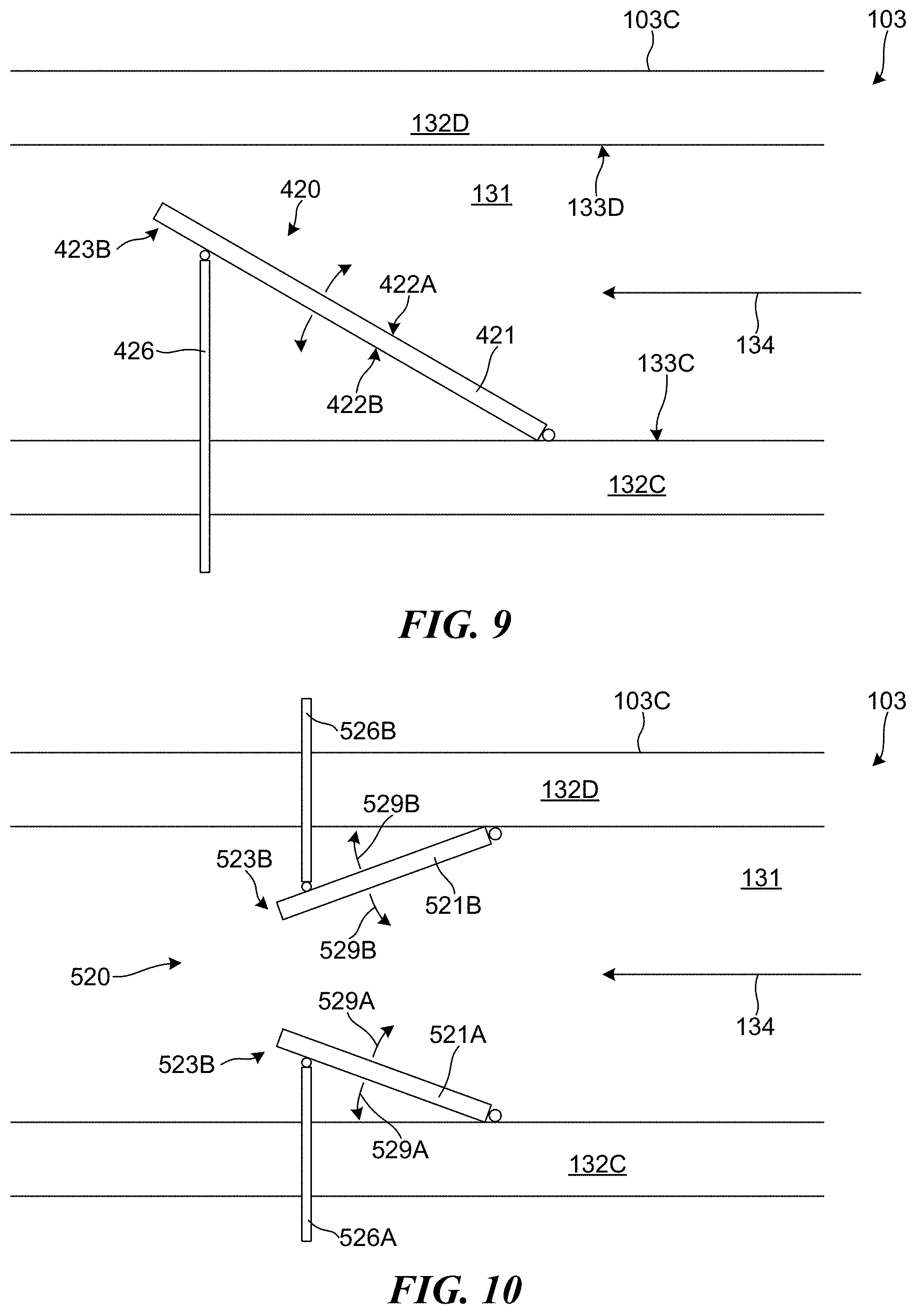
[0051] FIG. 9 shows a top-view of another alternative implementation of an uptake damper 420. In embodiments shown in FIGS. 4-8, the uptake damper is positioned on and coupled to the second refractory surface 133B of the lower wall 132B and the actuator assembly is used to move one of the end portion vertically to change the configuration of the uptake damper. In the embodiment shown in FIG. 9, however, the uptake damper 420 is coupled to the third refractory surface 133C of the first sidewall 132C and the rod 426, which is operatively coupled between the second end portion 423B and the actuator 127 shown in FIG. 4, extends through the first sidewall 132C and can be used to move the uptake damper 420 between different configurations by moving the second end portion 423B laterally. In this way, the second end portion 423B can be moved toward or away from the fourth refractory surface 133D of the second sidewall 132D to control the flow of gases through the channel 131 and to regulate the oven draft within the coke oven.
[0052] FIG. 10 shows a top-view of another alternative embodiment of an uptake damper 520. The uptake damper 520 can includes first and second damper plate 521A and 521B arranged to have a French-door configuration. The first damper plate 521A is pivotably coupled to the first sidewall 132C and can be rotated relative to the first sidewall 132C using the first rod 526A, as shown by arrows 529A. Similarly, the second damper plate 521B is pivotably coupled to the second sidewall 132D and can be rotated relative to the second sidewall 132D using the second rod 526B, as shown by arrows 529B. With this arrangement, the damper plates 521A and 521B can be rotated independent from each other. Accordingly, to move the uptake damper 520 between different configurations, one or both of the damper plates 521A and 521B can be rotated to different orientations. For example, the uptake damper 520 can be moved to a closed configuration by rotating the first and second damper plates 521A and 521B until the second end portions 5123B of both damper plates 521A and 521B are at a midpoint of the channel 131 and are touching each other. The uptake damper 520 can also be moved to a completely-open configuration by rotating the first and second damper plates 521A and 521b until the damper plates are positioned directly against the respective sidewalls 132C and 132D. The uptake damper 520 can also be moved to still other configurations by only moving one of the damper plates 521A and 521B, without moving the other damper plate. In general, the first and second damper plates 521A and 521B can be moved to any suitable orientation that restricts the flow of gases within the channel 131 to a selected flow rate. In the illustrated embodiment, the first and second damper plates 521A and 521B are approximately the same size and positioned adjacent to each other. In other embodiments, however, the first and second damper plates 521A and 521B can have a different size and/or can be positioned offset from each other.
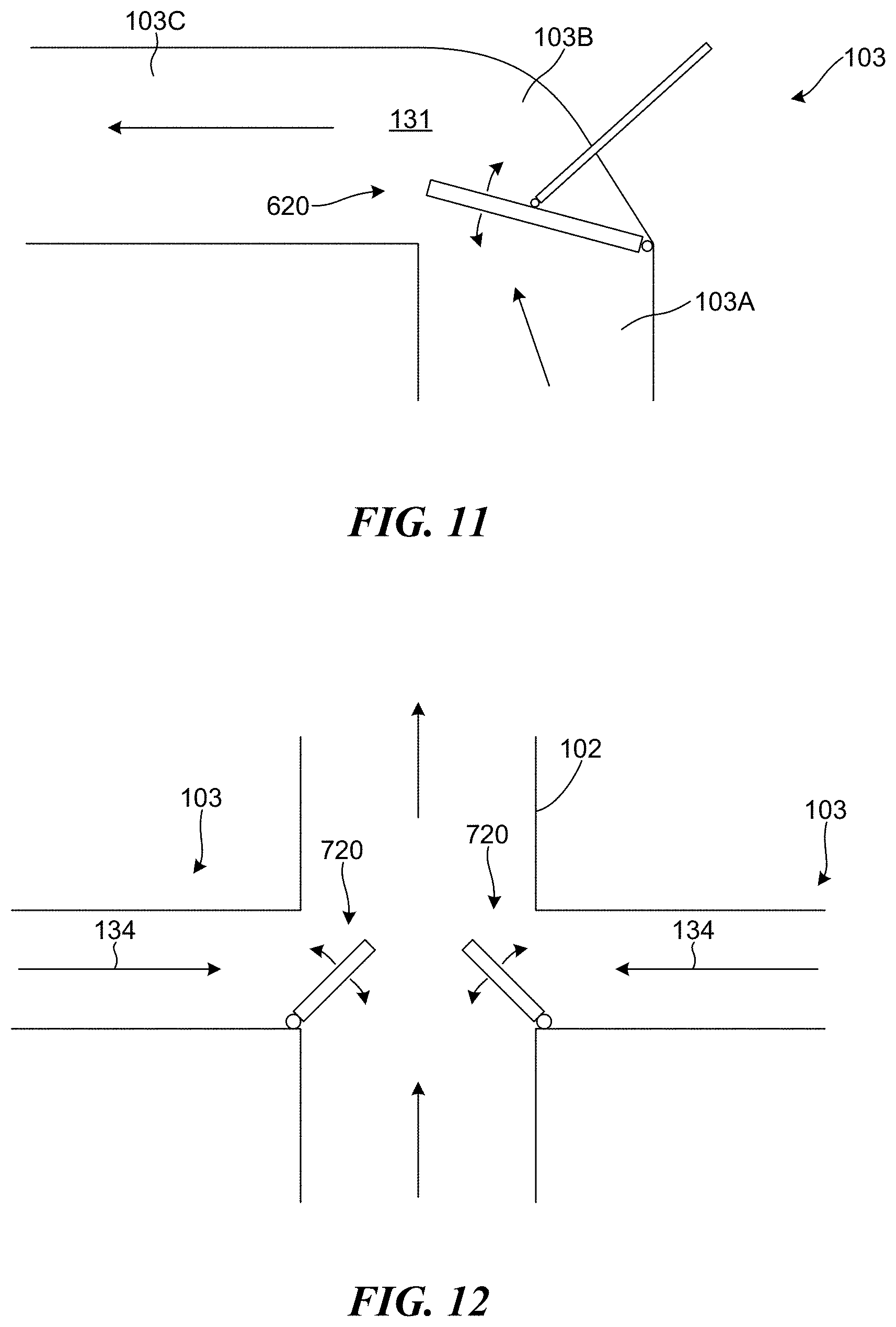
[0053] In the embodiments shown in FIGS. 4-10, the uptake dampers are shown as being formed in the horizontal segment 103C of the uptake duct 103. In other embodiments, however, the uptake damper can be incorporated into a different portion of the uptake duct 103. For example, FIG. 11 shows a diagram of an uptake damper 620 formed in the bent segment 103B. With this arrangement, the uptake duct 620 can be used to prevent gases within the vertical segment 103A from reaching the horizontal segment 103C. In still other embodiments, the uptake duct 103 can include multiple of the uptake dampers 620 such that one of the uptake dampers 620 is positioned within the bent segment 103B while a different uptake damper 620 is positioned within the horizontal segment 103C. The uptake dampers 620 can also be used in conjunction with other damper structures, such as a damper plate hanging vertically from the upper wall that can be raised and/or lowered to a selected position within the channel 131.
[0054] In still other embodiments, the uptake damper can be positioned between the uptake duct 103 and the common tunnel 102. FIG. 12 shows a top-view of the common tunnel 102 and two uptake ducts 103 coupled to the common tunnel 102. In representative embodiments, the two uptake ducts are coupled to the same oven 101 such that the exhaust gas flowing from the two uptake ducts 103 into the common tunnel 102 is from the same uptake oven 101. Both of the update ducts 103 can include an uptake damper 720 coupled between the uptake ducts 103 and the common tunnel 102. The uptake dampers 720 can be configured to swing laterally so as to regulate the amount of exhaust gas that can flow from the uptake duct into the common tunnel 102. Further, when the uptake dampers 720 are in a partially-open configuration, the uptake dampers 720 can act as a deflector that directs exhaust gases leaving the uptake ducts 103 downstream, which can reduce turbulence within the common tunnel 102.
[0055] In each of the previously illustrated embodiments, the damper plates of the uptake dampers are controlled movable using a rod that extends through a wall of the uptake duct and couples to the damper plate. In other embodiments, however, the damper plates can be controlled using other movement systems. For example, in some embodiments, a wire or cable that extends through an opposing sidewall can be used to pull the damper plate to a selected orientation. In some embodiments, the wire or cable can be coupled to a pivot pin coupled to the end portion of the damper plate. In other embodiments, the damper plate can be coupled to an electric or magnetic hinge that can rotate the damper plate to the selected rotation. In general, any suitable movement system capable of withstanding elevated temperatures can be used to move the damper plate to a selected orientation.
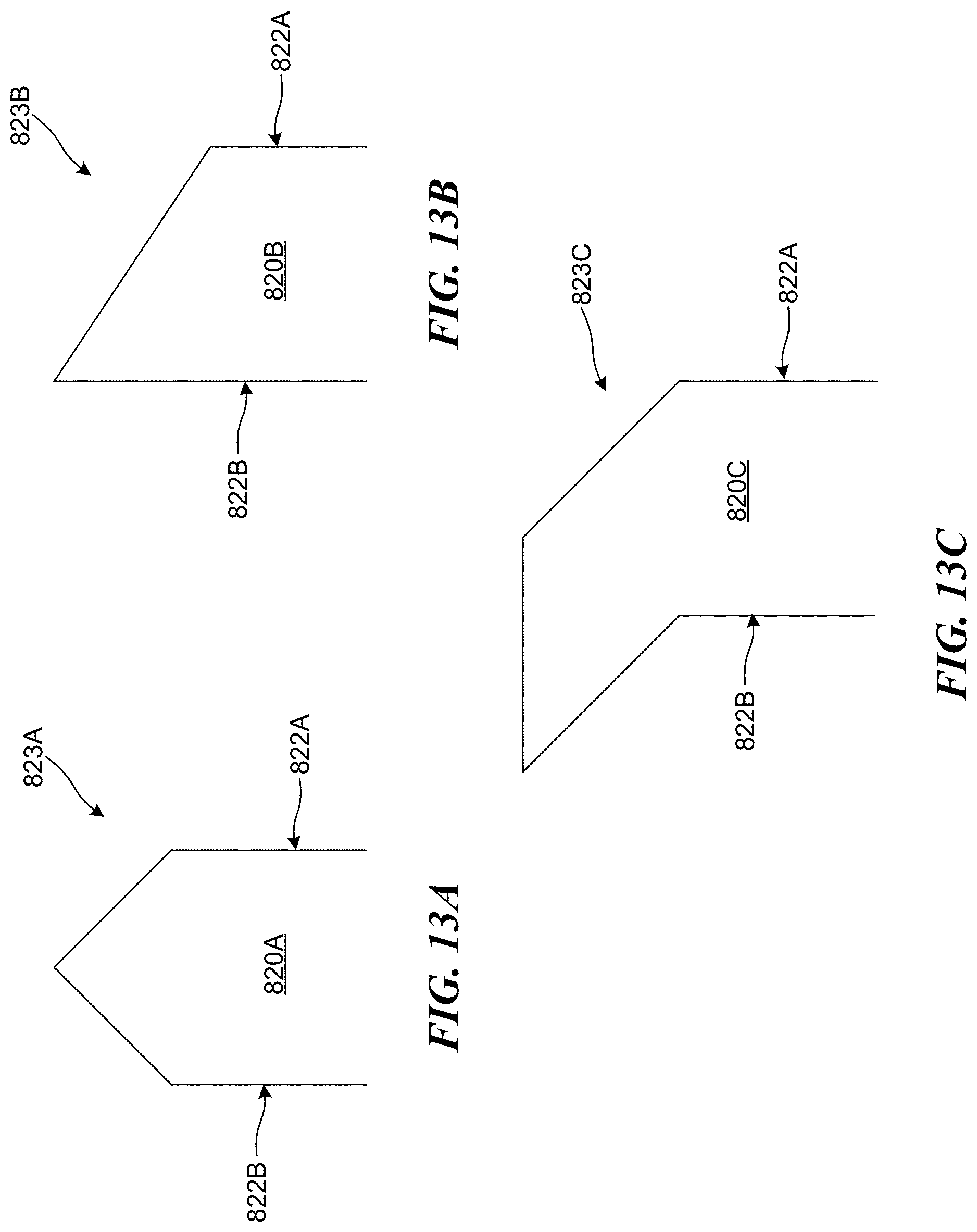
[0056] In each of the previously illustrated embodiments, the damper plates for each of the uptake dampers have been depicted as being flat and rectangular plates and having a rectangular edge portions. In other embodiments, however, the damper plates can have a different shape. For example, the damper plates can be curved, angled, or any other suitable shape that provides good mating with walls of the channel 103. In still other embodiments, edge portions of the damper plates can be shaped to reduce recirculation of exhaust gases and minimize ash build up on the back of the plate as the exhaust gases flow past the damper plates. FIGS. 13A-C show examples of differently-shaped edge portions 823. Specifically, FIG. 13A shows a side elevation view of an edge portion 823A having a pointed shape, FIG. 13B shows a side elevation view of an edge portion 823B having a sloped shape, and FIG. 13C shows a side elevation view of an edge portion 823C having a swept shape. Each of these shapes can allow exhaust gases to more efficiently flow past the edge portions 823A-C, which can improve the operation of the uptake ducts and uptake dampers.
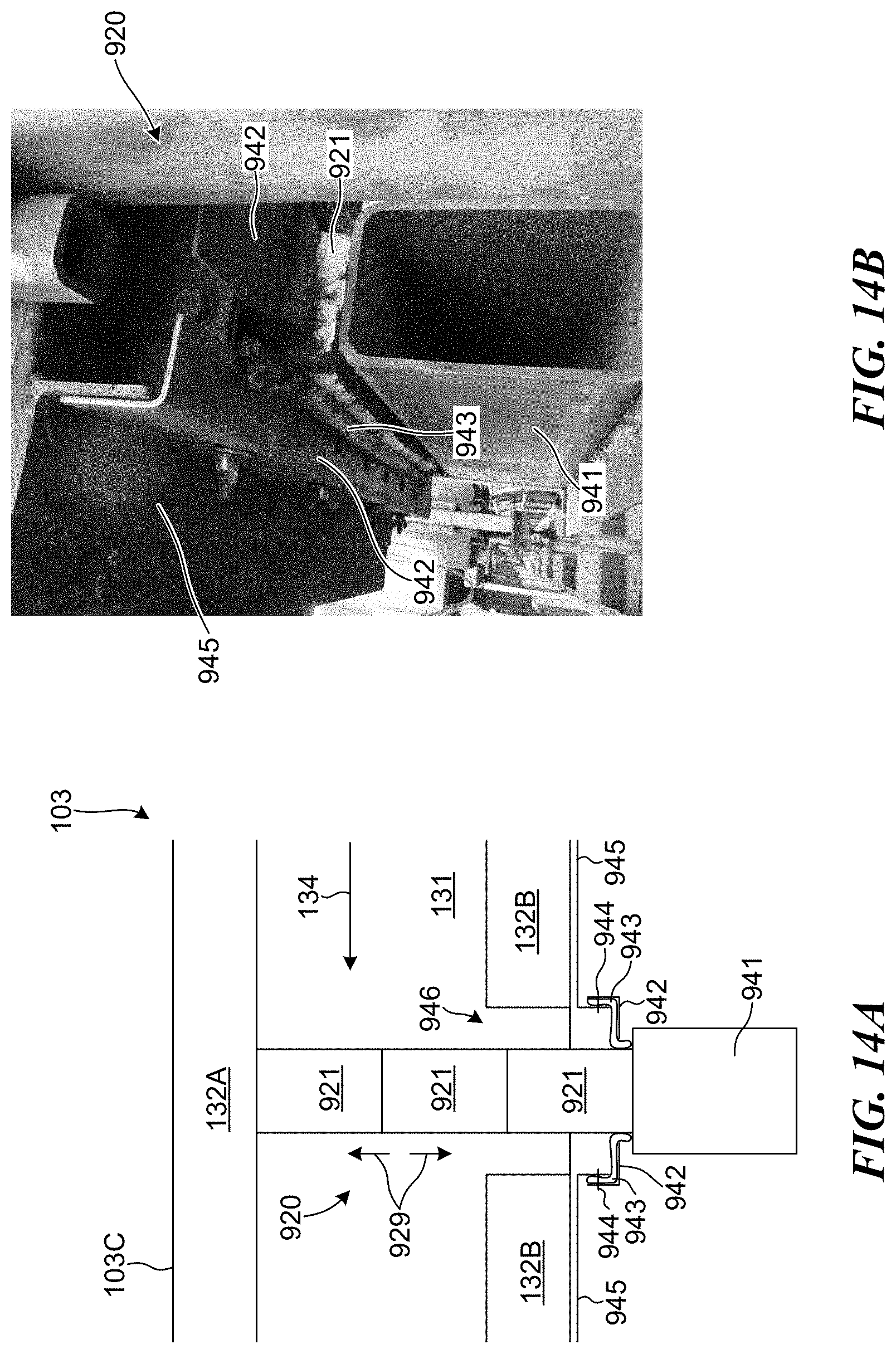
[0057] In the previously illustrated embodiments, the uptake damper is shown as including a plate structure that can be moved into a selected position and orientation by pivoting the plate structure. In other embodiments, however, the uptake damper can include one or more blocks that can be moved into a selected position by linearly moving into and out of the channel 131. For example, FIGS. 14A and 14B show an uptake damper 920 that includes three damper blocks 921 stacked together and configured to be moved vertically into and out of the channel 131, as shown by arrows 929. The damper blocks 921 are stacked together and positioned in an opening 946 formed through the lower wall 946 of the horizontal segment 103C and positioned on a piece of square piping 941 located outside of the uptake duct 103. An actuator coupled to the piping 941 can be used to raise and lower the damper blocks 921 to a selected height within the channel 131. In some embodiments, the weight of the damper blocks 921 can be used to lower the uptake damper while the actuator is used to raise the uptake damper. In other embodiments, the actuator is used to both raise and lower the uptake damper. However, the opening 946 can sometimes allow hot gases within the channel 131 to leak out of the uptake duct 103 even if the uptake damper 920 is in a closed configuration, which can result in heat and pressure being undesirably lost from the coke oven. To reduce the amount of gas and heat that can escape from the uptake duct 103 via the opening 946, the uptake damper 920 can include insulation that helps to at least partially seal the opening 946. The uptake duct 103 includes a metal plate 945 that forms an outer surface for the uptake duct 103. The uptake damper 920 can include an L-shaped bracket 942 that is positioned adjacent to a portion of the metal plate 945 and that extends around the opening 946 and the damper block 921. Insulation 943 is positioned such that a first portion of the insulation 943 is sandwiched between the metal plate 945 and the bracket 942 while a second portion of the insulation 943 extends toward the damper block 921 and even extends past the bracket 942. Securing mechanisms, such as bolts 944, can be used to securely couple the metal plate 945, the insulation 943, and the bracket 942 together to hold the insulation 943 in place. With this configuration, the insulation 943 can reduce the amount of exhaust and heat than can pass escape from the uptake duct 103 via the opening 946. However, this arrangement of the insulation 943, the bracket 942, bolts 944, and metal plate 945 is only an example. In other embodiments, the bracket 942 can be a flat plate and wing nuts can be used to adjust the seal. In still other embodiments, other seal designs and configurations can be used. For example, in some embodiments, the seal can be mechanically actuated such that it is pressed against the damper blocks 921 to affect a better seal when the uptake duct is in use. Correspondingly, when the damper blocks 921 are being moved into or out of the channel 131, the seal can be mechanically actuated so that it is released from the pressing against the damper blocks 921.
[0058] In some embodiments, the insulation 943 can include Kaowool. The Kaowool can be formed into a tad-pole seal having a bulb portion and a tail portion and the insulation 943 can be positioned such that the bolt 944 extends through the tail portion while the bulb portion is positioned between the bracket 942 and the damper block 921. In this way, the insulation 943 can help to seal off the opening 946. In other embodiments, however, the insulation can include other materials, such as woven cloth formed from ceramic fibers or a bristle brush material, and can have a different shape. In general, the insulation 943 can be formed from any suitable material, or combination of materials, and can have any suitable shape that allows the insulation 943 to at least partially seal the opening 946 while also withstanding the high temperatures present within the channel 131.
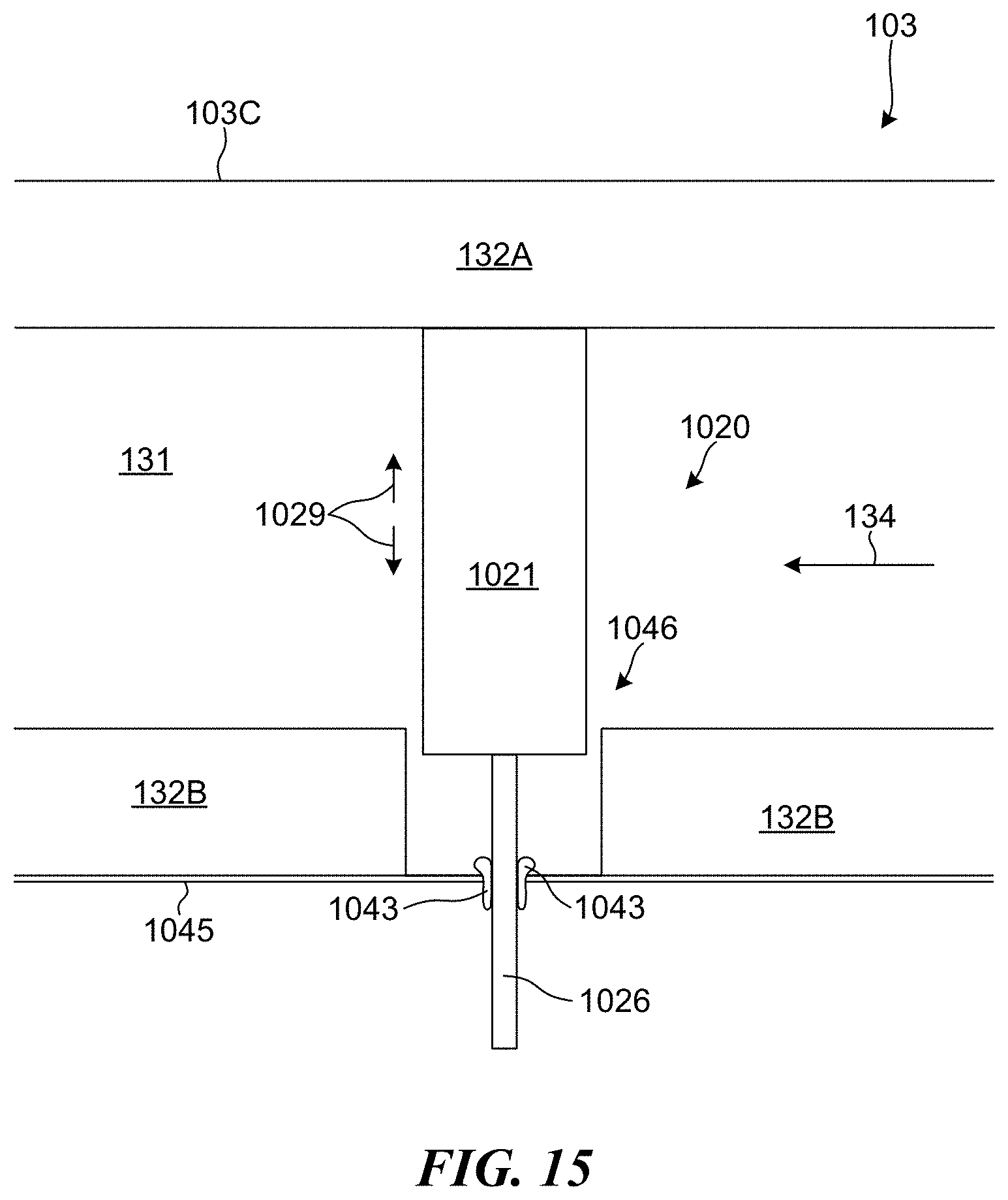
[0059] FIG. 15 shows an alternative uptake damper to the structure shown in FIGS. 14A and 14B. In the embodiment shown in FIG. 15, the uptake damper 1020 includes a single damper block 1021 that is positioned entirely within the uptake duct 103. The damper plate 1021 can be sized and shaped to extend across the entire height of the channel 131 and is supported by one or more rods 1026. The one or more rods 1026 extend through the opening 1046 formed in the lower wall 132B and through plate 1045 and is coupled to an actuator that can be used to move the damper block 1021 vertically, as shown by arrows 1029. The actuator used to move the damper block 1021 can be capable of raising the damper block 1021 while relying on gravity to lower the damper block 1021, or can be capable of both raising and lowering the damper block 1021. In some embodiments, the plate 1045 is formed from metal. In other embodiments, however, the plate 1045 is formed from cast refractory block that is coupled to the lower wall 132B. To reduce the amount of gas and heat that can escape from the uptake duct 103 by passing through the opening 1046 and through the opening in the plate 1045, the uptake damper 1020 can include insulation 1043 that is positioned around the rod 1026. In some embodiments, a seal is provided around the rod 1026, such as a mechanically actuatable seal. When a mechanically actuated seal is used, the seal can be actuated to press more firmly against the rid 1026 when the uptake duct is in use. Correspondingly, the seal can be actuated to release from against the rod when the damper block 1021 is being moved into or out of the channel 131. Because the rods 1026 typically have smaller dimensions than the uptake block 1021, the size of the openings formed in the plate 1045 can be reduced, thus reducing the amount of space that gas can leak out of the duct 103 and reducing the amount of insulation 1043 (or the size of the seal) needed to sufficiently seal the opening.
[0060] While FIG. 15 illustrates a configuration using a single rod 1026 to raise and lower the damper block 1021, more than one rod can also be provided. In some embodiments, the damper block 1021 includes in its lower surface (i.e., the surface facing the lower wall 132B) a recess into which the rod 1026 can extend in order to couple together the rod 1026 and the damper block 1021. In some embodiments, the rod 1026 may be positively coupled with the damper block 1021, such as through the use of a material that is filled into the recess and hardens after the rod 1026 is inserted in the recess in the damper block 1021 (e.g., a cement-type material). In other embodiments, the rod 1026 is inserted in the recesses in the block 1021, but is otherwise not connected to the block 1021.
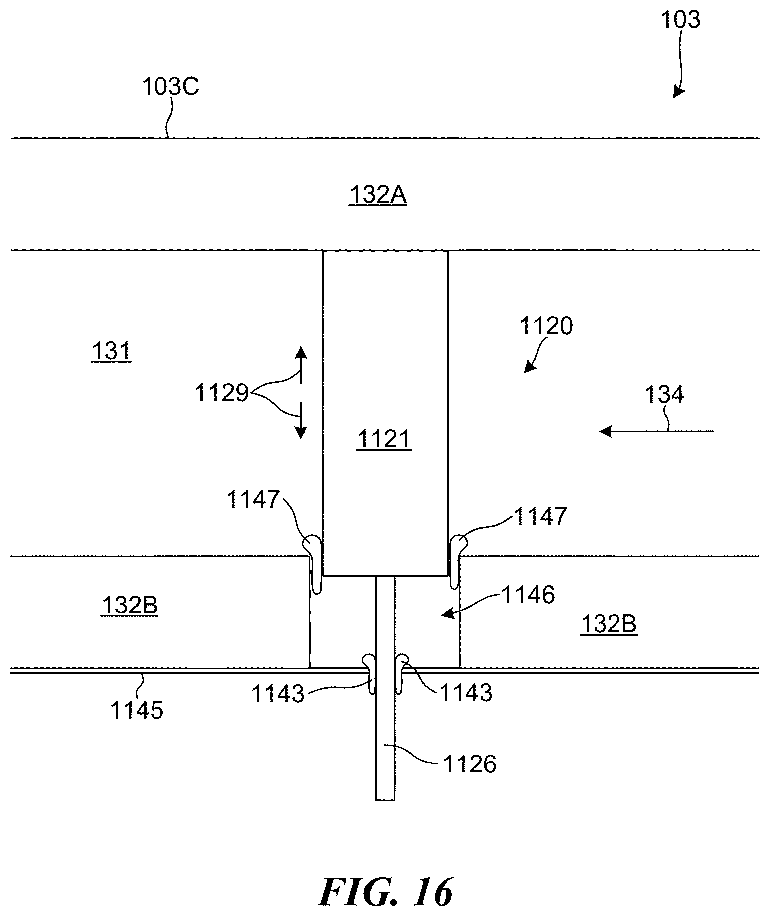
[0061] In some embodiments, the uptake damper can also include other insulation positioned within the opening and that can be used to restrict and/or prevent exhaust from passing by the uptake damper by passing under the damper block when the uptake damper 1020 is in a closed configuration. For example, FIG. 16 shows an alternative uptake damper to the 1120 to the structure shown in FIG. 15. The uptake damper 1120 includes insulation 1147 positioned around the opening 1146 and that is positioned between the damper block 1121 and the lower wall 132B. The insulation 1147 acts as a barrier that limits and/or prevents gas within the channel 131 from bypassing the uptake damper 1120 by passing into the opening 1146 and flowing under the damper block 1121. In some embodiments, the insulation 1147 can be a tad-pole seal.
[0062] FIG. 17 shows still another alternate embodiment to the damper blocks shown in FIGS. 14A-15. The damper block 1121 shown in FIG. 17 generally includes a box 1122 that serves as the base of the damper block 1121 and a block 1123 disposed on top of the box 1122. As with previous damper block embodiments, the damper block 1121 may be raised and/or lowered using one or more rods that contact the box 1122. In some embodiments, the bottom surface of the box 1122 includes a recess for each rod used to lower and/or raise the damper block 1121. The rod extends into the recess and can be positively connected to box 1122, or can reside within the recess without any additional means for connecting the rod to the box 1122. In some embodiments, the box 1122 is made from a metal material. In some embodiments, the block 1123 may be made from a refractory material. The block 1123 may be bolted or otherwise secured to the box 1122. In some embodiments, the damper block 1121 is dimensioned and installed in such a way that the box 1122 never enters the channel of the uptake duct. In other words, when the damper block 1121 is fully raised, the box 1122 remains outside of the channel of the uptake duct while the block 1123 is fully within the channel extends across the height of the channel. As with previous embodiments, insulation material and/or seals can be used to prevent gas and/or heat from escaping the uptake duct where the damper block 1121 extends into the channel. In some embodiments, a fiber insulation material is provided disposed in the gap in the uptake duct through which the damper block 1121 extends. In some embodiments, this fiber insulation will surround the box 1122 to prevent loss of heat and/or gas. In an alternate embodiment, the material of the block 1123 is a fiber board material, which is lightweight material compared to the refractory material that can be used for the block 1123. An exemplary, fiberboard material suitable for use as the block 1123 is Fibermax.RTM. Duraboard 1700 or Fibermax.RTM. Duraboard 1800, manufactured by Unifrax of Niagra Falls, N.Y.
[0063] Referring back to FIG. 3 and the general configuration wherein an uptake duct 103 is aligned orthogonally with the common tunnel 102, it is generally understood that under this configuration the flow of exhaust gas from the uptake duct 103 to the common tunnel 102 will include an approximately 90 degree turn when the exhaust gas transitions from the uptake duct 103 into the common tunnel 102. Accordingly, in some embodiments, an uptake damper system is provided that is configured to both control the amount of exhaust gas flowing through the uptake duct 103 and into the common tunnel 102 and the direction of the flow exhaust gas as it transitions form the uptake duct 103 to the common tunnel 102.
[0064] FIGS. 18A and 18B provide an illustration of an embodiment of an uptake damper 1220 configured to control exhaust gas flow and direction. The uptake damper 1220 generally comprises a cylinder 1221 having a passage 1222 extending through the cylinder 1221. The cylinder 1221 is fully rotatable such that the passage 1222 can be oriented in any direction. For example, in some embodiments, the cylinder 1221 is oriented such that the passage 1222 is aligned in parallel with the longitudinal axis of the horizontal segment 103c of the uptake duct 103. In such a configuration, exhaust gas passing through the passage 1222 (i.e., from the uptake duct 103 into the common tunnel 102) will enter the common tunnel at a direction generally orthogonal to the flow of exhaust gas travelling through the common tunnel. However, when the cylinder 1221 is rotated such that the passage 1222 is oriented, e.g., at a 45 degree angle to the longitudinal axis of the horizontal segment 103c of the uptake duct, gas passing through the passage 1222 will arrive into the common tunnel at a 45 degree angle to the gas flowing through the common tunnel, which can allow for improved integration between gas already in the common tunnel 102 and gas entering the common tunnel 102 via an uptake duct 103. FIG. 18B illustrates the scenario in which the cylinder 1221 of the uptake damper 1220 is rotated such that the passage 1222 is oriented at a 45 degree angle. As shown in FIG. 18B, gas flowing through the horizontal segment 103c merges towards the left side of the horizontal segment 103c so that it can enter the passage 1222, whose opening is positioned closer to the left side of the horizontal segment 103c due to the 45 degree orientation. The gas then flows through the passage 1222 and exits into the common tunnel 102 at an angle approximately equal to the angle of the passage 1222. Because the gas enters the common tunnel 102 at an angle that is closer to the direction of flow of gas through the common tunnel 102, the gas is able to better integrate with the gas already flowing through the common tunnel 102.
[0065] As shown in FIG. 18B, the uptake damper 1220 is positioned at the terminal end of the horizontal segment 103c of the uptake duct 103. That is to say, the uptake damper 1220 is positioned so that it is effectively located at the junction point between the horizontal segment 103c of the uptake duct 103 and the common tunnel 102. In fact, in some embodiments, a portion of the uptake damper 1220 may be positioned within the common tunnel 102. This helps to ensure that gas exiting the passage 1222 of the uptake damper 1220 enters into the common tunnel 102 and merges with the gas in the common tunnel 102 at the angle at which the passage 1222 is oriented.
[0066] As noted above, the uptake damper 1220 can be rotated so that the passage 1222 is oriented in any desired direction. Provided that the openings of the passage 1222 are still able to receive gas from the uptake duct 103 and expel gas into the common tunnel 102, the angle of orientation can be lowered below, e.g., 45 degrees to attempt to provide an even smoother integration between the gas passing through the uptake damper 1220 and the gas already travelling through the common tunnel 102. In some embodiments, as the cylinder 1221 is rotated such that the openings of the passage 1222 become blocked, the uptake damper 1220 can also be used to control the amount of flow through the uptake damper 1220. Further still, when the cylinder 1221 is rotated such that the openings of the passage 1222 are fully blocked (e.g., wherein the passage 1222 is at a 90 degree angle to the longitudinal axis of the horizontal segment 103c of the uptake duct 103, the uptake damper 1220 can fully prevent flow of gas from the uptake duct 103 to the common tunnel 102.
[0067] FIG. 18A illustrates an embodiment of the uptake damper 1220 where a partition 1223 is disposed within the passage 1222 in a direction parallel to passage 1222. The partition 1223 can generally extend the length of the passage 1222. The partition 1223 can have any thickness, but will generally have a relatively small profile so as to not overly impede flow of gas through the passage 1222. The partition 1223 shown in FIG. 18A has a thickness that increases from a first end to the middle of the partition 1223, before decreasing from the middle of the partition 1223 to a second end of the partition 1223 to thereby form a generally "cat's eye" shape when viewed from above. However, it should be appreciated that any shape partition can be used. For example, in some embodiments, the partition 1223 can be curved so as to further aid changing the direction of the gas flowing through the uptake damper 1220.
[0068] While FIG. 18A illustrates an uptake damper 1220 that includes partition 1223, it should be appreciated that the uptake damper 1220 can also be used without a partition 1223, such that the passage 1222 is free of any obstructions. FIG. 18A also generally illustrates a straight line passage 1222 having a uniform width, though it should be appreciated that the passage 1222 could be curved and/or having a varying width along its length.
[0069] Any manner of rotating the uptake damper 1220 can be used. In some embodiments, a rod is attached to the bottom or top surface of the cylinder 1221, and the rod can be rotated in order to rotate the cylinder 1220. The rod preferably does not extend into the passage 1222 of the cylinder 1221 so as not provide an obstruction within the passage 1222.
[0070] FIGS. 19A-19D illustrate an alternate embodiment of the uptake damper 1220 shown in FIGS. 18A and 18B in which two concentric cylinders are used to form uptake damper 1320. As shown in FIG. 19, which is a top down view of the uptake damper 1320 positioned at the terminal end of a horizontal segment 103c of an uptake damper (i.e., at the junction between the horizontal segment 103 and the common tunnel 102), the uptake damper 1320 comprises an outer cylinder 1321 and an inner cylinder 1322 concentrically aligned with the outer cylinder 1321. The outer cylinder 1321 has a hollow interior region into which the inner cylinder 1322 is disposed. As such, the outer cylinder 1321 has an outer diameter and an inner diameter, with the inner diameter defining the size of the hollow interior region. In this configuration, the outer cylinder 1321 effectively forms a rotatable shell around the inner cylinder 1322. The outer cylinder has two openings 1321a opposite each other and two side walls 1321b opposite each other. The openings 1321a and the side walls 1321b extend the height of the outer cylinder 1321, with the openings 1321a providing passage into and out of the inner cylinder 1322 and the side walls 1321b serving to block off the inner cylinder 1322, depending on the rotation of the outer cylinder 1321. For example, as shown in FIG. 19A, when the openings 1321a in outer cylinder 1321 are positioned to be upstream and downstream of the inner cylinder 1322, gas flowing through the horizontal segment 103c towards the common tunnel 102 can flow into and through the inner cylinder 1322. FIG. 19B, on the other hand, shows an embodiment where the outer cylinder 1321 has been rotated 45 degrees such that the sidewalls 1321b are positioned downstream and upstream of the inner cylinder 1322. In this configuration, the sidewalls block gas flowing into and through the inner cylinder 1322. Thus, by rotating the outer cylinder 1321 to the desired position, the flow of gas through the inner cylinder 1322 can be allowed or prohibited. The outer cylinder 1321 can also be positioned to allow limited flow into the inner cylinder 1322, such as when the sidewalls 1321b are positioned to partially but not fully block the inner cylinder 1322.
[0071] The inner cylinder 1322 has an outer diameter that is approximately equal to the inner diameter of the outer cylinder 1321 so that the inner cylinder 1322 can be disposed within the hollow interior of the outer cylinder 1321. The inner cylinder 1322 includes a plurality of partitions 1322a located in the interior of the inner cylinder 1322 and extending the height of the inner cylinder 1322. These partitions 1322a form a series of channels 1322b extending across the width of the inner cylinder 1322, with gas being capable of flowing through these channels 1322b. As shown in FIG. 19A, the partitions 1322a are straight walls forming a series of straight channels 1322b extending through the inner cylinder 1322. The inner cylinder 1322 is capable of being rotated independent of the outer cylinder 1321 such that the partitions 1322a can be oriented at any angle relative to the longitudinal axis of the horizontal segment 103c. In FIG. 19A, the inner cylinder 1322 has been rotated so that the partitions 1322a are aligned in parallel with the longitudinal axis of the horizontal segment 103c. Because the outer cylinder 1321 is rotated such that the openings 1321a are upstream and downstream of the inner cylinder 1322, gas can flow into the inner cylinder 1322, through the channels 1322a aligned in parallel with the longitudinal axis of the horizontal segment 103c and into the common tunnel 102, with the gas entering the common tunnel 102 at an angle approximately orthogonal to the flow of gas through the common tunnel 103.
[0072] With reference to FIG. 19C, the outer cylinder 1321 can remain in the same position as shown in FIG. 19A, while the inner cylinder 1322 is rotated, e.g., 45 degrees so that the partitions 1322a and channels 1322b are oriented at a 45 degree angle to the longitudinal axis of the horizontal segment 103c. In this configuration, the flow of gas flowing through the uptake damper 1320 will be directed into a common tunnel 102 at an approximately 45 degree angle such that the gas entering the common tunnel 102 from the uptake damper 103 will better integrate with the gas already flowing through the common tunnel 102. The inner cylinder 1322 can be rotated to any position such that gas flowing through the uptake damper 1320 can be redirected and made to enter the common tunnel 102 at practically any desired angle.
[0073] While FIGS. 19A-19C show straight partitions 1322a and straight channels 1322b, it should be appreciated that the partitions 1322a of inner cylinder 1322 can be given any shape to better adjust the angle of gas flowing through the uptake damper 1320. For example, as shown in FIG. 19D, the partitions 1322a are curved to thereby form curved channels 1322b. In this configuration, the inner cylinder 1322 can still be rotated freely, such that the curved partitions 1322a can be set at a more or less severe angle, depending on the desired operating conditions.
[0074] As with the cylinder 1221 shown in FIGS. 18A and 18B, the outer cylinder 1321 and the inner cylinder 1322 can be rotated using any suitable means, such as a rod attached to the top of bottom surface of the inner cylinder 1322 and/or the outer cylinder 1321. Such rods preferably do not extend into the interior of the cylinders so as to not obstruct the flow of gas through the cylinders.
[0075] While FIGS. 18A-19D illustrate embodiments of a cylindrical-style damper block that is positioned proximate the junction of the horizontal segment 103c and the common tunnel 102 for directing exhaust gas entering the common tunnel from the uptake duct 103, it should be appreciated that cylindrical-style damper blocks as shown in FIGS. 18A-19D can be used at any location in a duct system where changing the direction of the exhaust gas is desired. For example, the cylindrical-style damper blocks shown in FIGS. 18A-19D could be used at any other turn in a duct system, including but not limited to, in a bent segment 103b between a vertical segment 103a and a horizontal segment 103c of an uptake duct. Positioning in a cylindrical-style damper block at such a location can assist with directing the exhaust gas through the 90 degree turn between the vertical segment 103a and the horizontal segment 103c. In such an embodiment, the cylindrical-style damper block may be positioned such that the axis of the cylindrical damper block is horizontal (rather than vertical as shown in FIGS. 18A-19D).
[0076] From the foregoing, it will be appreciated that specific embodiments of the invention have been described herein for purposes of illustration, but that various modifications may be made without deviating from the scope of the invention. Accordingly, the invention is not limited except as by the appended claims.
* * * * *
D00000
D00001
D00002
D00003
D00004
D00005
D00006
D00007
D00008
D00009
D00010
D00011
D00012
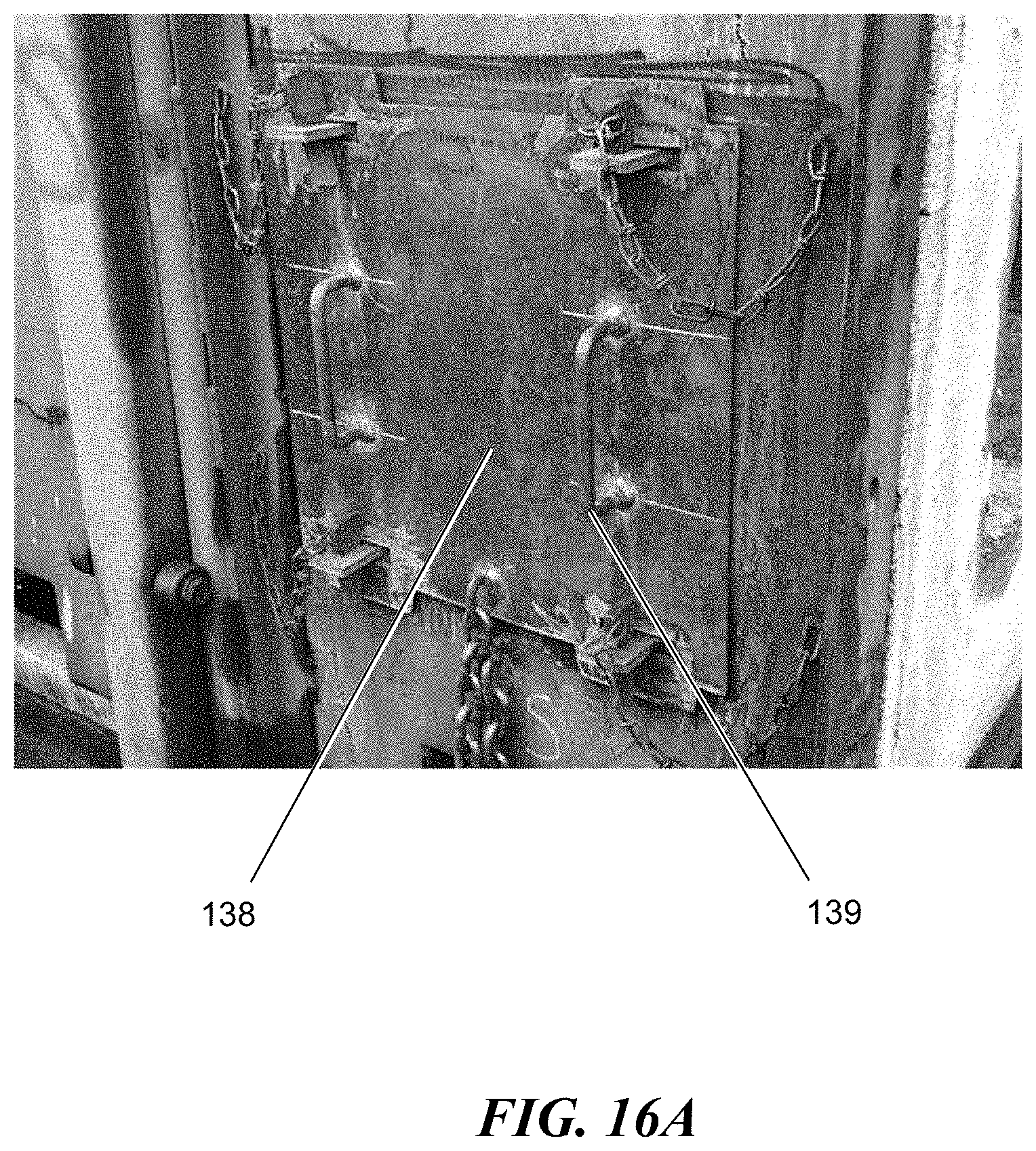
D00013
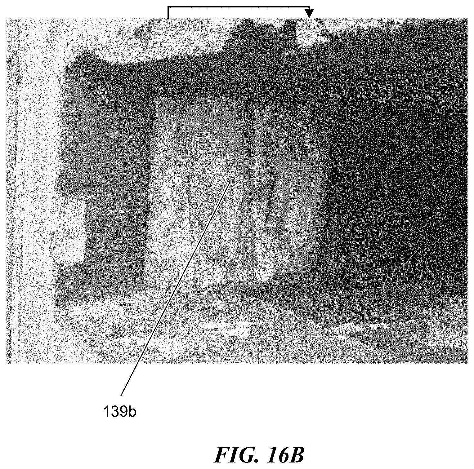
D00014
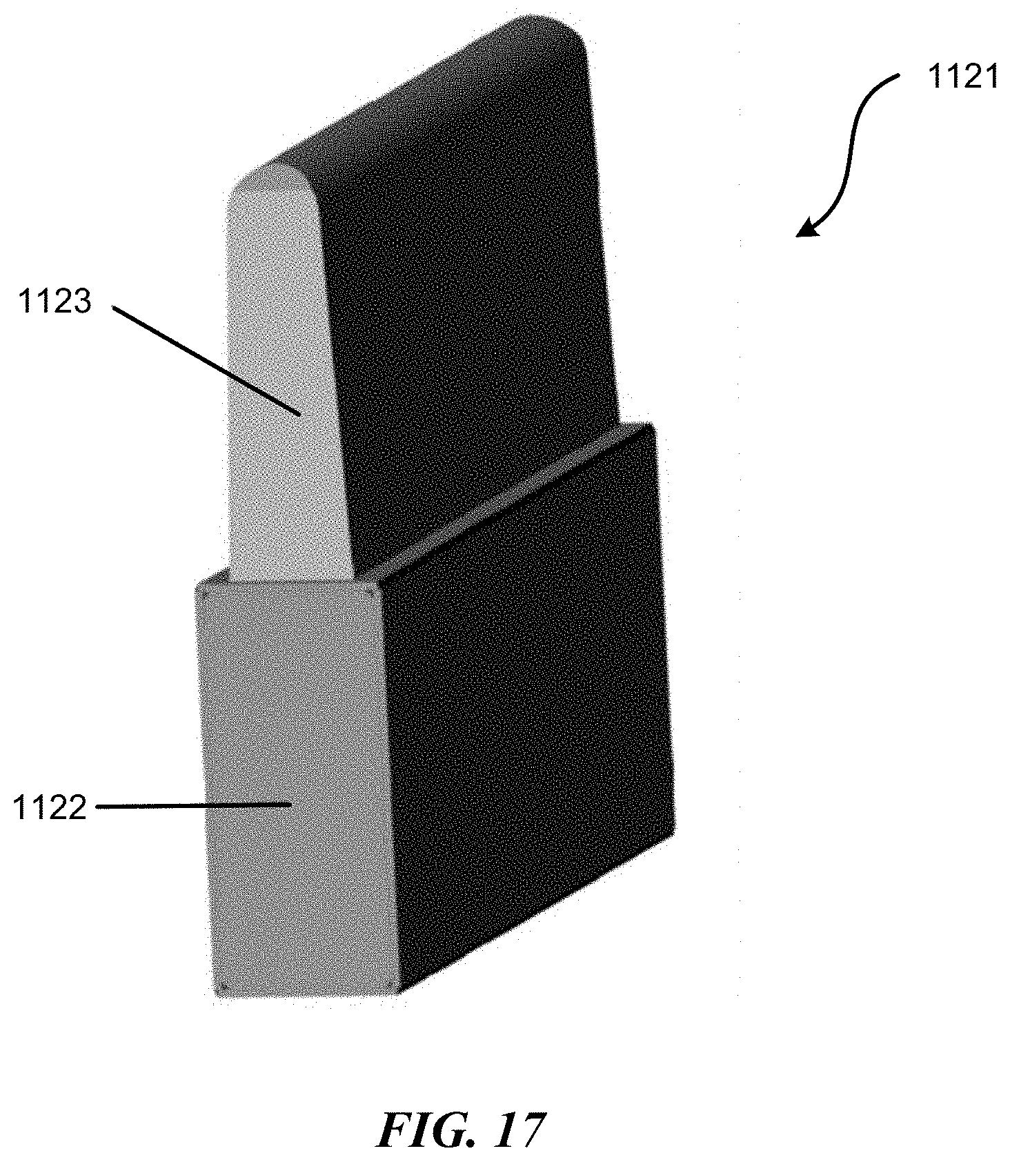
D00015
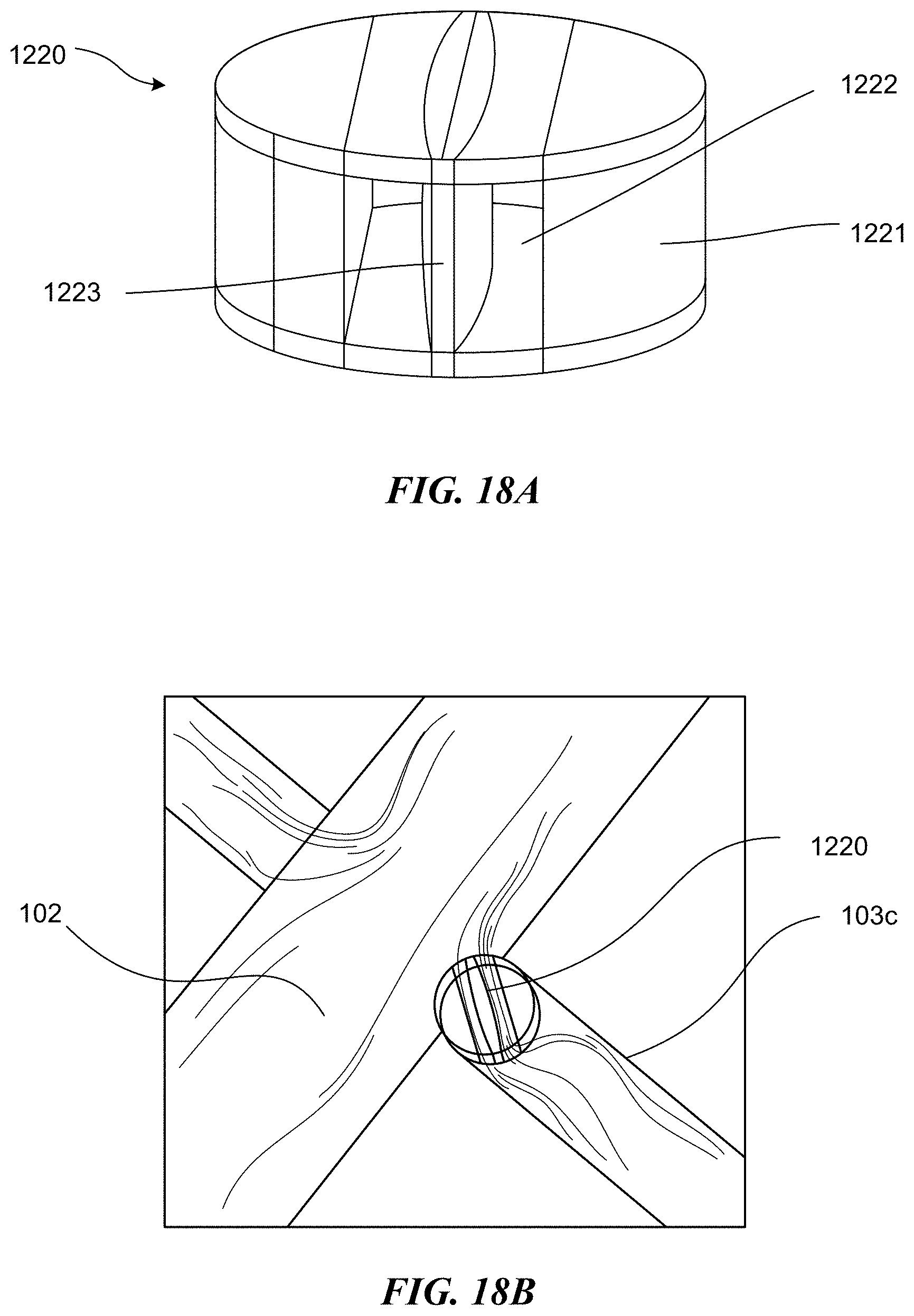
D00016
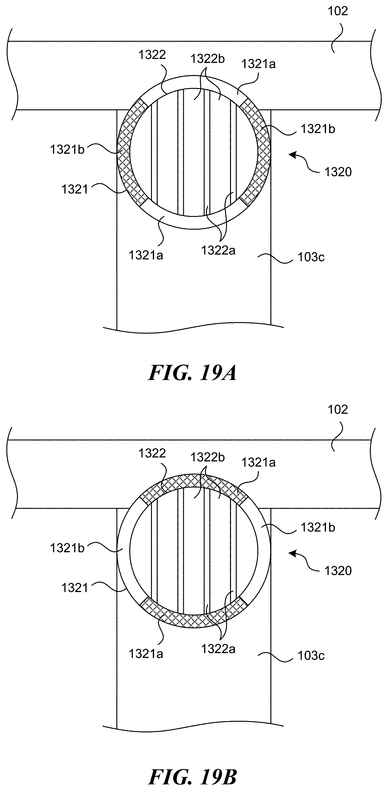
D00017
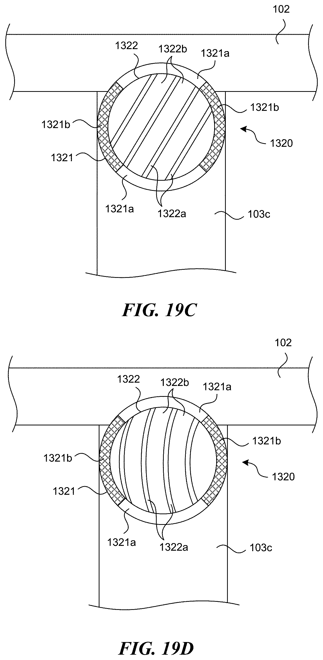
XML
uspto.report is an independent third-party trademark research tool that is not affiliated, endorsed, or sponsored by the United States Patent and Trademark Office (USPTO) or any other governmental organization. The information provided by uspto.report is based on publicly available data at the time of writing and is intended for informational purposes only.
While we strive to provide accurate and up-to-date information, we do not guarantee the accuracy, completeness, reliability, or suitability of the information displayed on this site. The use of this site is at your own risk. Any reliance you place on such information is therefore strictly at your own risk.
All official trademark data, including owner information, should be verified by visiting the official USPTO website at www.uspto.gov. This site is not intended to replace professional legal advice and should not be used as a substitute for consulting with a legal professional who is knowledgeable about trademark law.