Container Having Multiple Separate Internal Reservoirs
Yeping; Li
U.S. patent application number 16/245799 was filed with the patent office on 2020-07-02 for container having multiple separate internal reservoirs. The applicant listed for this patent is ZHEJIANG KAIDA STATIONERY CO., LTD.. Invention is credited to Li Yeping.
| Application Number | 20200207536 16/245799 |
| Document ID | / |
| Family ID | 71122585 |
| Filed Date | 2020-07-02 |


| United States Patent Application | 20200207536 |
| Kind Code | A1 |
| Yeping; Li | July 2, 2020 |
CONTAINER HAVING MULTIPLE SEPARATE INTERNAL RESERVOIRS
Abstract
A multi-reservoir container comprising a first reservoir, wherein the first reservoir includes a body having an interior cavity and a first dispensing aperture in communication with the interior cavity of the first reservoir; and a second reservoir removably disposed within a portion of the interior cavity of the first reservoir, wherein the second reservoir includes a body having an interior cavity; a first cap formed around the body that engages the first dispensing aperture in a sealable manner; a second dispensing aperture in communication with the interior cavity of the second reservoir; and a second cap that engages the second dispensing aperture in a sealable manner.
| Inventors: | Yeping; Li; (Hangzhou, CN) | ||||||||||
| Applicant: |
|
||||||||||
|---|---|---|---|---|---|---|---|---|---|---|---|
| Family ID: | 71122585 | ||||||||||
| Appl. No.: | 16/245799 | ||||||||||
| Filed: | January 11, 2019 |
Related U.S. Patent Documents
| Application Number | Filing Date | Patent Number | ||
|---|---|---|---|---|
| 62785496 | Dec 27, 2018 | |||
| Current U.S. Class: | 1/1 |
| Current CPC Class: | B65D 1/0223 20130101; B65D 81/3216 20130101; B65D 2251/0078 20130101; B65D 2251/0015 20130101; B65D 41/0407 20130101 |
| International Class: | B65D 81/32 20060101 B65D081/32; B65D 41/04 20060101 B65D041/04; B65D 1/02 20060101 B65D001/02 |
Claims
1.-6 (canceled)
7. A multi-reservoir container, comprising: (a) a first reservoir, wherein the first reservoir includes a body having an interior cavity and a first dispensing aperture in communication with the interior cavity of the first reservoir; and (b) a second reservoir removably disposed within a portion of the interior cavity of the first reservoir, wherein the second reservoir includes: (i) a body having an interior cavity; (ii) a first cap formed around the body that engages the first dispensing aperture in a sealable manner; (iii) a second dispensing aperture in communication with the interior cavity of the second reservoir, wherein the second dispensing aperture includes a hollow threaded stem; and (iv) a second cap, wherein the second cap is hollow and includes threads that mechanically engage the hollow threaded stem in an adjustable manner such that when the second cap is tightened, a seal is formed, and when the second cap is loosened, but not entirely removed from the hollow threaded stem, material may be dispensed from an aperture formed in the second cap.
8. The multi-reservoir container of claim 7, further comprising a first dispensable material contained within the first reservoir and a second dispensable material contained in the second reservoir, wherein the first material is different than the second material.
9. The multi-reservoir container of claim 7, wherein the shape of the body is quasi-elliptical.
10. The multi-reservoir container of claim 7, wherein the shape of the body is quasi-elliptical and includes at least one contoured region formed therein.
11. The multi-reservoir container of claim 7, wherein the body of the first reservoir further includes a hollow threaded stem in communication with the interior cavity of the first reservoir, and wherein the first cap includes threads that mechanically engage the hollow threaded stem on the body of the first reservoir to form a seal therewith.
12-14. (canceled)
15. A multi-reservoir container, comprising: (a) a first reservoir, wherein the first reservoir includes: (i) a body having an exterior surface and an interior cavity; (ii) a hollow stem located on the exterior surface of the body, wherein the hollow stem is in communication with the interior cavity of the first reservoir; (b) a second reservoir removably disposed within a portion of the interior cavity of the first reservoir, wherein the second reservoir includes: (i) a body having an exterior surface, an interior cavity, a lower portion, and an upper portion; (ii) a first cap located on the upper portion of the body, wherein the first cap further includes a lower portion and an upper portion, wherein the lower portion engages the hollow stem located on the first reservoir in a sealable manner, wherein the upper portion further includes a hollow stem in communication with the interior cavity of the second reservoir, and wherein the hollow stem in communication with the interior cavity of the second reservoir is threaded; and (c) a second cap, wherein the second cap includes threads that mechanically engage the threads on the hollow threaded stem in communication with the interior cavity of the second reservoir in an adjustable manner such that when the second cap is tightened, a seal is formed, and when the second cap is loosened, but not entirely removed from the hollow threaded stem, material may be dispensed from an aperture formed in the second cap.
16. The multi-reservoir container of claim 15, further comprising a first dispensable material contained within the first reservoir and a second dispensable material contained in the second reservoir, wherein the first material is different than the second material.
17. The multi-reservoir container of claim 15, wherein the shape of the body is quasi-elliptical.
18. The multi-reservoir container of claim 15, wherein the hollow stem located on the exterior surface of the body of the first reservoir is threaded, and wherein the first cap includes threads that mechanically engage the threads on the hollow stem on the body of the first reservoir to form a seal therewith.
19-20.(canceled)
Description
[0001] This patent application claims the benefit of U.S. Provisional Patent Application Ser. No. 62/785,496 filed on Dec. 27, 2018 and entitled "Container Having Multiple Separate Internal Reservoirs," the disclosure of which is hereby incorporated by reference herein in its entirety and made part of the present U.S. utility patent application for all purposes.
BACKGROUND OF THE INVENTION
[0002] The present invention relates generally to packages and containers for use with commercial products such as adhesives, paint, and the like and more specifically to a container that includes multiple internal reservoirs that are separated from one another in a manner that allows the container to store at least two fluid or viscous materials that differ from one another in their chemical and physical properties.
[0003] Most containers used for commercial products such as adhesives or paint include only a single internal reservoir for holding the contents of a container. When a multi-part adhesive system or other type of system requiring the sequential mixing of multiple materials having different chemical and physical properties (e.g., a resin and its curing agent) are sold commercially, a separate container is typically required for each material to prevent premature or unwanted mixing of the materials. The necessity of multiple, separate containers for such products add expense and complexity to the packaging process and is often inconvenient for the users of such products with regard to transporting and using the products. While certain containers for storing multiple different materials do exist, these containers are often expensive to manufacture and lack the aesthetic qualities that consumers expect with regard to containers traditionally used for do-it-yourself products (e.g., adhesives) and products for use with toys and stationery (e.g., paints, liquid glitter, etc.). Thus, there is an ongoing industrial and commercial need for a simplistic container that includes multiple, separate, internal reservoirs for storing at least two fluid or viscous materials that differ from one another in their chemical and physical properties and that meets the aesthetic and practical expectations of the typical consumer.
SUMMARY OF THE INVENTION
[0004] The following provides a summary of certain exemplary embodiments of the present invention. This summary is not an extensive overview and is not intended to identify key or critical aspects or elements of the present invention or to delineate its scope. However, it is to be understood that the use of indefinite articles in the language used to describe and claim the present invention is not intended in any way to limit the described system. Rather the use of "a" or "an" should be interpreted to mean "at least one" or "one or more".
[0005] In accordance with one aspect of the present invention, a first multi-reservoir container is provided. This multi-reservoir container comprises a first reservoir, wherein the first reservoir includes a body having an interior cavity and a first dispensing aperture in communication (e.g. fluid communication) with the interior cavity of the first reservoir; and a second reservoir removably disposed within a portion of the interior cavity of the first reservoir, wherein the second reservoir includes a body having an interior cavity and a cap that engages the first dispensing aperture in a sealable manner, and wherein the cap further includes a sealable second dispensing aperture in communication (e.g. fluid communication) with the interior cavity of the second reservoir.
[0006] In accordance with another aspect of the present invention, a second multi-reservoir container is provided. This multi-reservoir container comprises a first reservoir, wherein the first reservoir includes a body having an interior cavity and a first dispensing aperture in communication (e.g. fluid communication) with the interior cavity of the first reservoir; and a second reservoir removably disposed within a portion of the interior cavity of the first reservoir, wherein the second reservoir includes a body having an interior cavity; a first cap formed around the body that engages the first dispensing aperture in a sealable manner; a second dispensing aperture in communication (e.g. fluid communication) with the interior cavity of the second reservoir; and a second cap that engages the second dispensing aperture in a sealable manner.
[0007] In yet another aspect of this invention, a third multi-reservoir container is provided. This multi-reservoir container comprises a first reservoir, wherein the first reservoir includes a body having an exterior surface and an interior cavity; a hollow stem located on the exterior surface of the body, wherein the hollow stem is in communication (e.g. fluid communication) with the interior cavity of the first reservoir; a second reservoir removably disposed within a portion of the interior cavity of the first reservoir, wherein the second reservoir includes a body having an exterior surface, an interior cavity, a lower portion, and an upper portion; a first cap located on the upper portion of the body, wherein the first cap further includes a lower portion and an upper portion, wherein the lower portion engages the hollow stem located on the first reservoir in a sealable manner, and wherein the upper portion further includes a hollow stem in communication (e.g. fluid communication) with the interior cavity of the second reservoir; and a second cap, wherein the second cap engages the hollow stem located on the second reservoir in a sealable manner.
[0008] Additional features and aspects of the present invention will become apparent to those of ordinary skill in the art upon reading and understanding the following detailed description of the exemplary embodiments. As will be appreciated by the skilled artisan, further embodiments of the invention are possible without departing from the scope and spirit of the invention. Accordingly, the drawings and associated descriptions are to be regarded as illustrative and not restrictive in nature.
BRIEF DESCRIPTION OF THE DRAWINGS
[0009] The accompanying drawings, which are incorporated into and form a part of the specification, schematically illustrate one or more exemplary embodiments of the invention and, together with the general description given above and detailed description given below, serve to explain the principles of the invention, and wherein:
[0010] FIG. 1A is a cross-sectional front view of a multi-reservoir container in accordance with a first embodiment of the present invention, wherein the multi-reservoir container is shown in an assembled state;
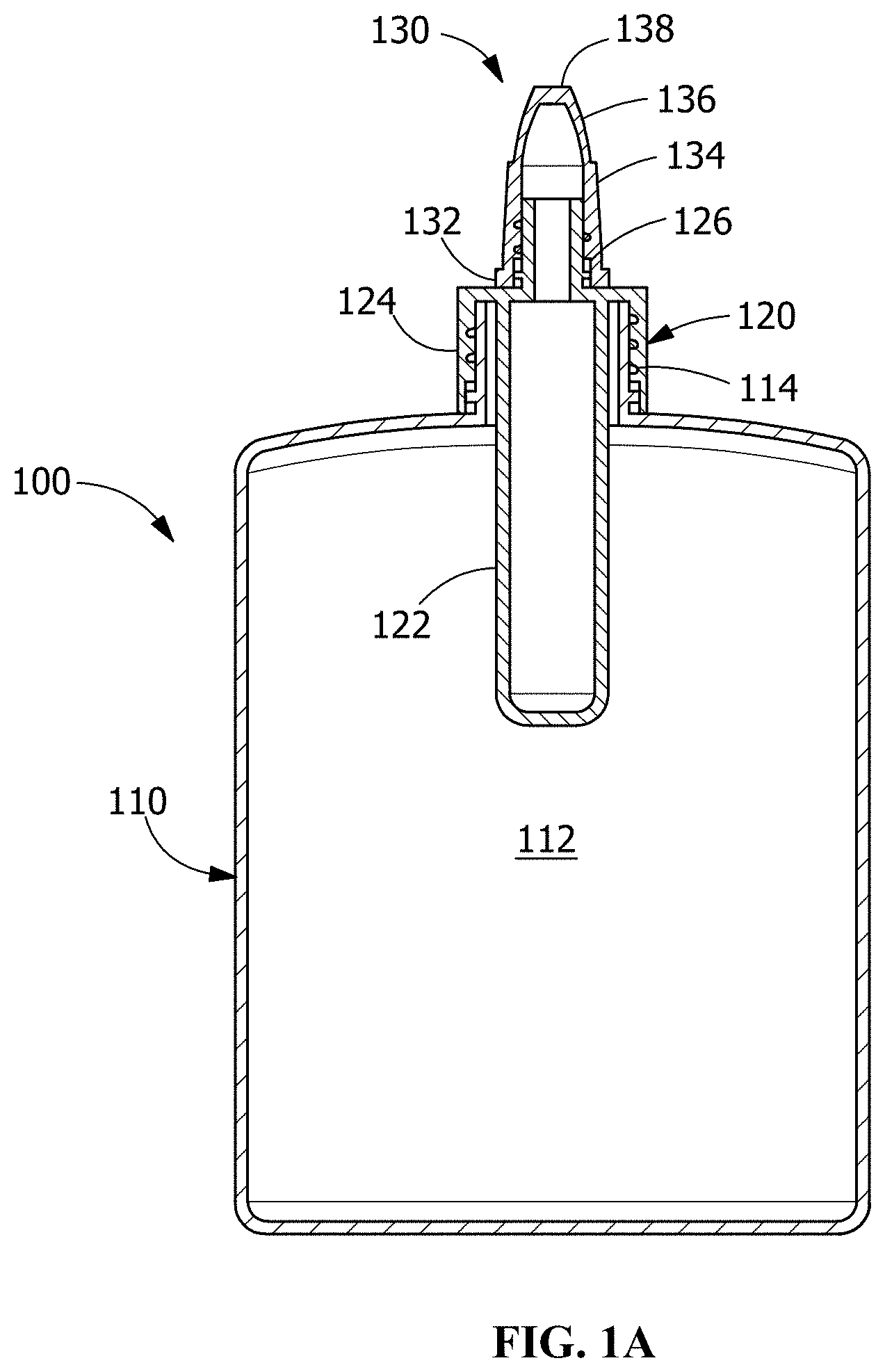
[0011] FIG. 1B is a front view of the multi-reservoir container of FIG. 1A, wherein the multi-reservoir container is shown in an exploded state;
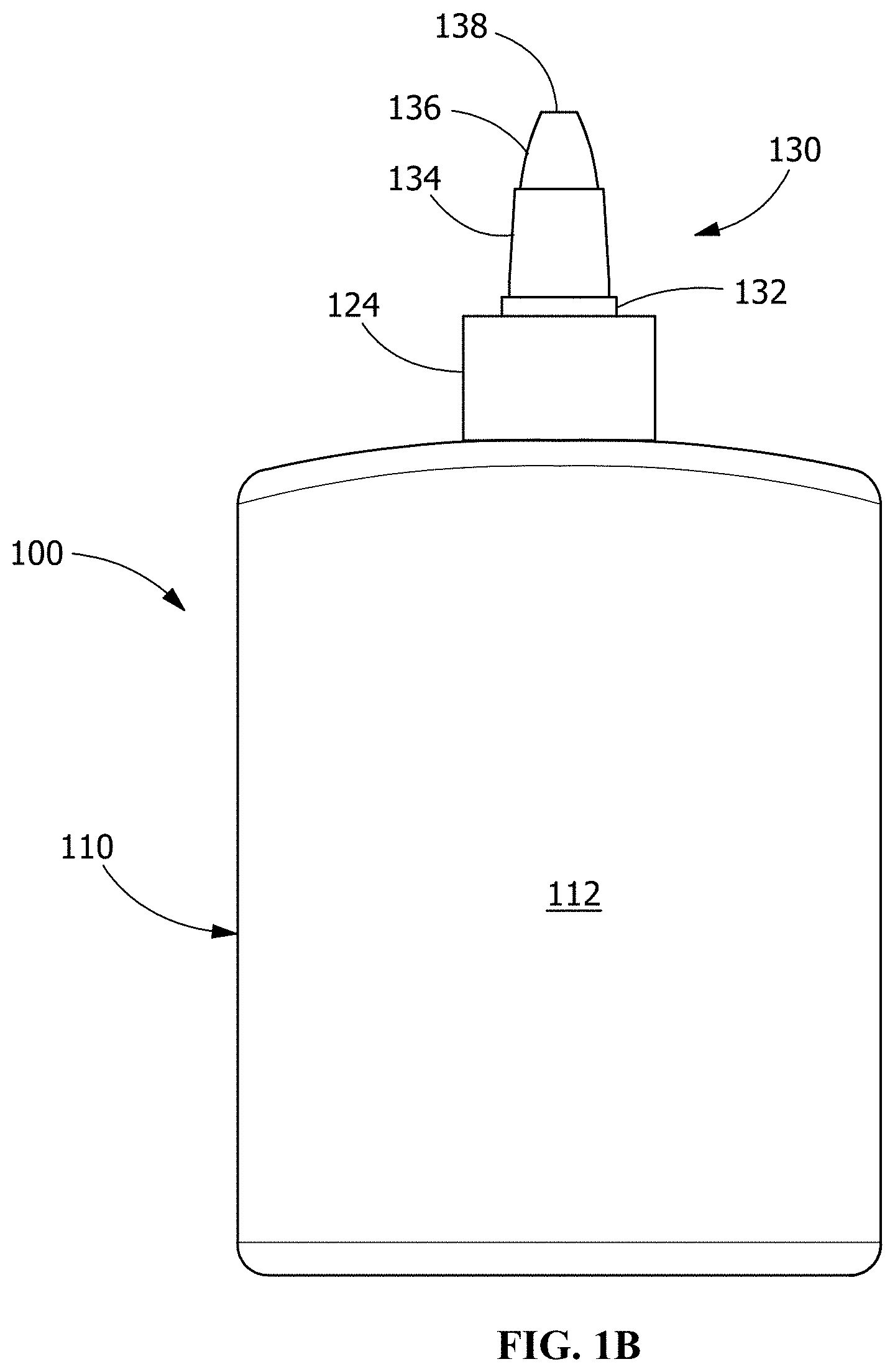
[0012] FIG. 1C is a front view of the multi-reservoir container of FIG. 1A, wherein the multi-reservoir container is shown in a fully assembled state;
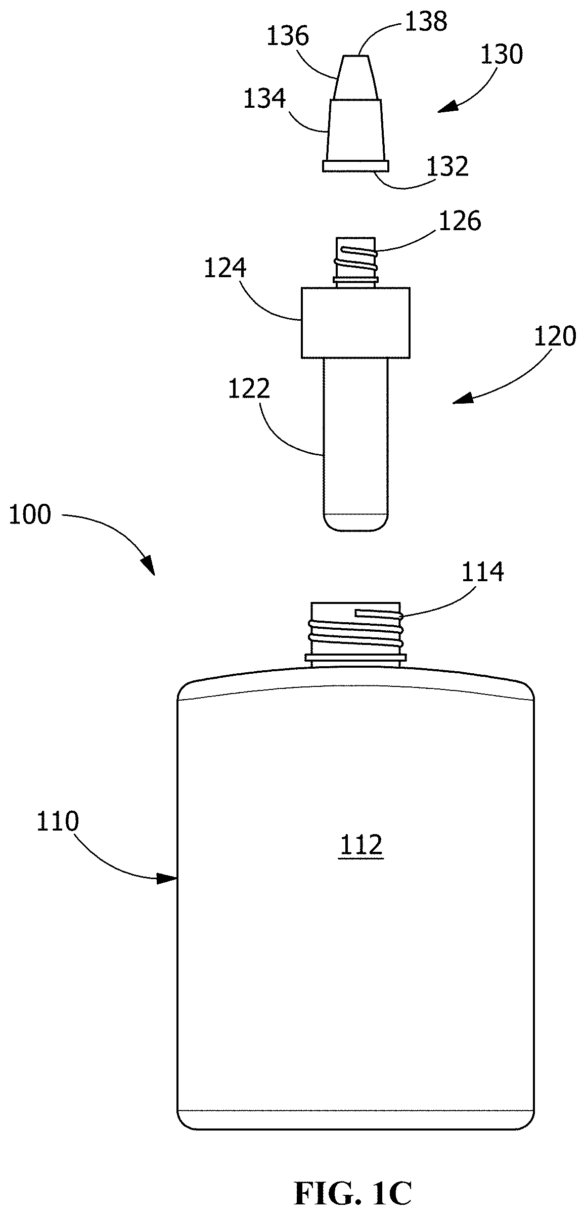
[0013] FIG. 2 is a perspective view of a multi-reservoir container in accordance with a second embodiment of the present invention, wherein the multi-reservoir container is shown in an exploded state;
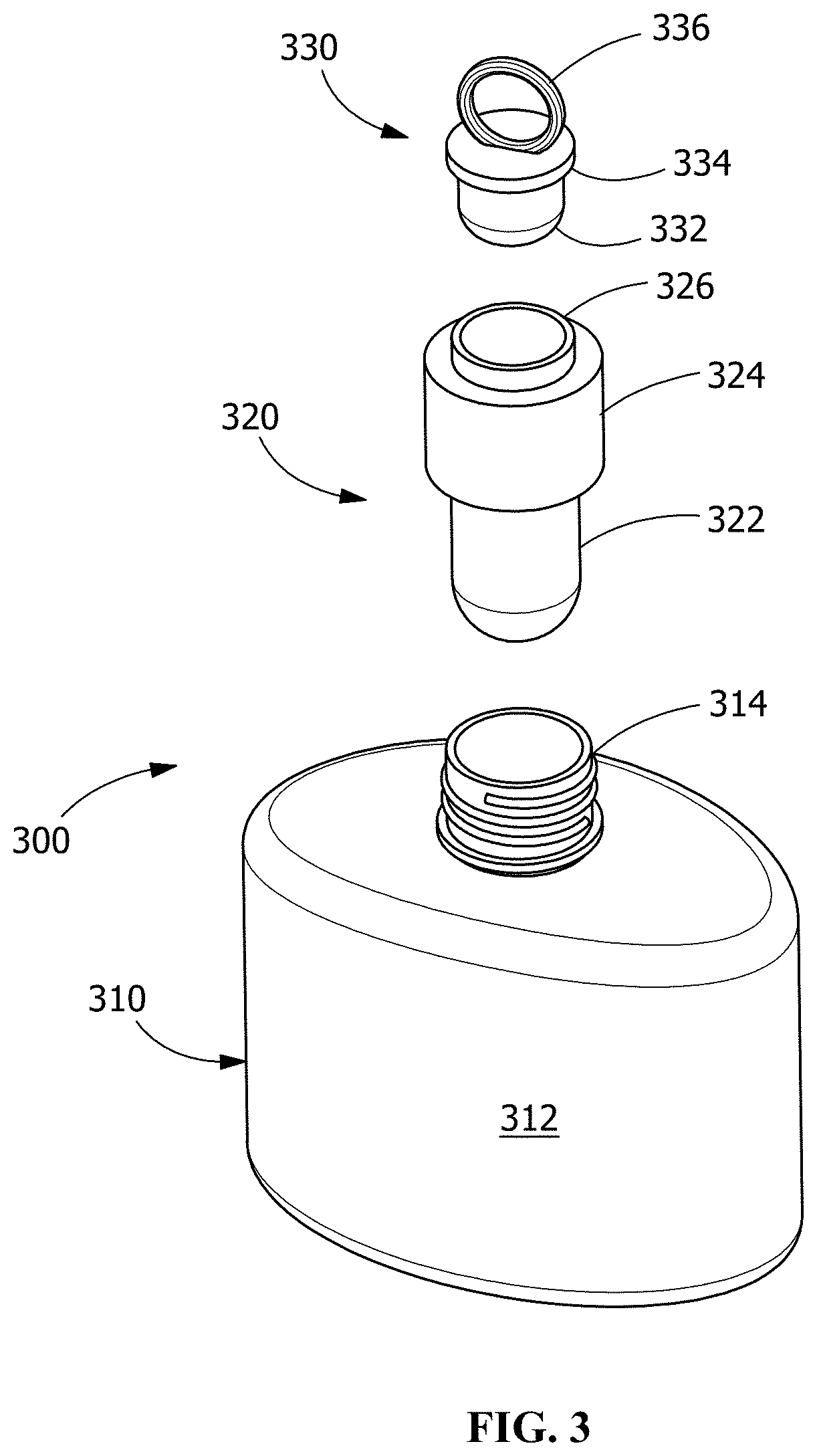
[0014] FIG. 3 is a perspective view of a multi-reservoir container in accordance with a third embodiment of the present invention, wherein the multi-reservoir container is shown in an exploded state; and
[0015] FIG. 4 is a perspective view of a multi-reservoir container in accordance with a fourth embodiment of the present invention, wherein the multi-reservoir container is shown in an exploded state.
DETAILED DESCRIPTION OF THE INVENTION
[0016] Exemplary embodiments of the present invention are now described with reference to the Figures. Although the following detailed description contains many specifics for purposes of illustration, a person of ordinary skill in the art will appreciate that many variations and alterations to the following details are within the scope of the invention. Accordingly, the following embodiments of the invention are set forth without any loss of generality to, and without imposing limitations upon, the claimed invention.
[0017] As previously described, the present invention provides a multi-reservoir container for use in storing materials that have different physical and chemical properties while preventing unwanted mixing or cross-contamination of the materials stored in the separated reservoirs. Essentially, the present invention provides a "bottle within a bottle" configuration that meets the expectations of the typical consumer with regard to ease of use, aesthetics, and basic functionality. Various embodiments of the multi-reservoir container of this invention are described in greater detail below. The described embodiments are provided for purpose of example and are not intended to be exhaustive in nature.
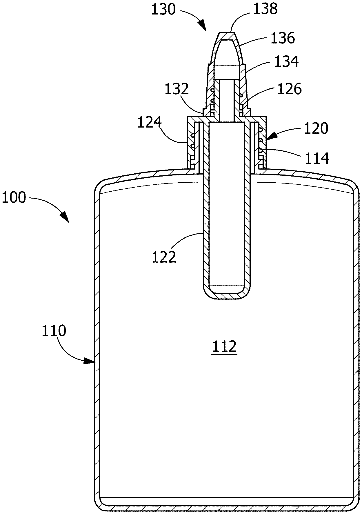
[0018] FIG. 1A provides a cross-sectional front view of a multi-reservoir container in accordance with a first embodiment of the present invention, wherein multi-reservoir container 100 is shown in an assembled state; FIG. 1B is a front view of multi-reservoir container 100 shown in an exploded state; and FIG. 1C is a front view of multi-reservoir container 100 shown in a fully assembled state. As shown in these Figures, multi-reservoir container 100 includes primary reservoir 110, which further includes body 112 having exemplary dimensions of 30 cm.sup.2.times.10 cm. Body 112 includes an interior cavity for holding/storing a first dispensable material therein and hollow stem 114, which in the embodiment shown in the Figures is threaded and serves as a dispensing aperture. Body 112, which may be quasi-elliptical in shape, is adapted to receive a portion of secondary reservoir 120 therein (see FIG. 1A). Secondary reservoir 120 (having exemplary dimensions of 6 cm.sup.2.times.8 cm) includes cylindrical body 122, which further includes an interior cavity for holding/storing a second dispensable material therein, and hollow stem 126, which in the embodiment shown in the Figures is threaded and which serves as a dispensing aperture. Secondary reservoir 120 also includes first sealing cap 124, which in this exemplary embodiment is threaded on its interior surface (not shown in the Figures) for engaging the threads on hollow stem 114 and forming a seal therewith when tightened. Second sealing cap 130 includes base 132, tapered middle section 134, and tapered upper section 136, which in some embodiments further includes dispensing tip 138, through which the material in secondary reservoir 120 may be dispensed. Although not shown in the Figures, second sealing cap 130 is threaded on its interior surface for engaging the threads on hollow stem 126 and forming a seal therewith when tightened. In certain embodiments, second sealing cap 130 engages hollow threaded stem 126 in a rotational mechanical relationship that permits material to be dispensed through dispensing tip 138 when second sealing cap 130 is loosened, but not entirely removed from hollow threaded stem 126. In certain variants of this embodiment, body 112 is non-transparent (e.g., through coloration, painting, or the placement of a label) and secondary reservoir 120 is seated within primary reservoir 110 toward the rear portion of the assembly in a manner that makes secondary reservoir not visible through body 112. This relationship between the two reservoirs is intended to enhance the aesthetics of the entire assembly/construction.
[0019] FIG. 2 provides a perspective view of a multi-reservoir container in accordance with a second embodiment of the present invention, wherein multi-reservoir container 200 is shown in an exploded state. As shown in these Figures, multi-reservoir container 200 is very similar to multi-reservoir container 100 and includes primary reservoir 210, which further includes body 212 having exemplary dimensions of 30 cm.sup.2.times.10 cm. Body 212 includes an interior cavity for holding/storing a first dispensable material therein and hollow stem 214, which in the embodiment shown in the Figures is threaded and serves as a dispensing aperture. Body 212, which may be flattened or quasi-elliptical in shape and which includes multiple contoured regions 216, is adapted to receive a portion of secondary reservoir 220 therein (in a manner similar to what is shown in FIG. 1A). Secondary reservoir 220 (having exemplary dimensions of 4.5 cm.sup.2.times.6 cm) includes cylindrical body 222, which further includes an interior cavity for holding/storing a second dispensable material therein, and hollow stem 226, which in the embodiment shown in the Figures is threaded and which serves as a dispensing aperture. Secondary reservoir 220 also includes first sealing cap 224, which in this exemplary embodiment is threaded on its interior surface (not shown in the Figures) for engaging the threads on hollow stem 214 and forming a seal therewith when tightened. Second sealing cap 230 includes base 232, tapered middle section 234, and tapered upper section 236, which in some embodiments further includes dispensing tip 238, through which the material in secondary reservoir 220 may be dispensed. Although not shown in the Figure, second sealing cap 230 is threaded on its interior surface for engaging the threads on hollow stem 226 and forming a seal therewith when tightened. In certain embodiments, second sealing cap 230 engages hollow threaded stem 226 in a rotational mechanical relationship that permits material to be dispensed through dispensing tip 238 when second sealing cap 230 is loosened, but not entirely removed from hollow threaded stem 226. In certain variants of this embodiment, body 212 is non-transparent (e.g., through coloration, painting, or the placement of a label) and secondary reservoir 220 is seated within primary reservoir 210 toward the rear portion of the assembly in a manner that makes secondary reservoir not visible through body 212. This relationship between the two reservoirs is intended to enhance the aesthetics of the entire assembly/construction.
[0020] FIG. 3 provides a perspective view of a multi-reservoir container in accordance with a third embodiment of the present invention, wherein multi-reservoir container 300 is shown in an exploded state. As shown in these Figures, multi-reservoir container 300 includes primary reservoir 310 (having exemplary dimensions of 40 cm.sup.2.times.6 cm), which further includes body 312. Body 312 includes an interior cavity for holding/storing a first dispensable material therein and hollow stem 314, which in the embodiment shown in the Figures is threaded and serves as a dispensing aperture. Body 312, which may be quasi-elliptical in shape, is adapted to receive a portion of secondary reservoir 320 therein (in a manner similar to what is shown in FIG. 1A). Secondary reservoir 320 (having exemplary dimensions of 6 cm.sup.2.times.3 cm) includes cylindrical body 322, which further includes an interior cavity for holding/storing a second dispensable material therein, and hollow stem 326, which in the embodiment shown in the Figures is threaded and which serves as a dispensing aperture. Secondary reservoir 320 also includes first sealing cap 324, which in this exemplary embodiment is threaded on its interior surface (not shown in the Figure) for engaging the threads on hollow stem 314 and forming a seal therewith when tightened. Second sealing cap 330 includes base 332 (which is a plug-like structure for forming a seal with hollow stem 326), lid 324, and pull ring 326, which is used to remove second sealing cap 330 from hollow stem 326 when desired.
[0021] FIG. 4 provides a perspective view of a multi-reservoir container in accordance with a fourth embodiment of the present invention, wherein multi-reservoir container 400 is shown in an exploded state. As shown in these Figures, multi-reservoir container 400 includes cylindrical primary reservoir 410 (having exemplary dimensions of 20 cm.sup.2.times.8 cm), which further includes body 412. Body 412 includes an interior cavity for holding/storing a first dispensable material therein and hollow stem 414, which in the embodiment shown in the Figures is threaded and serves as a dispensing aperture. Secondary reservoir 420 (having exemplary dimensions of 12 cm.sup.2.times.3 cm) includes cylindrical body 422, which further includes an interior cavity for holding/storing a second dispensable material therein and sealing cap 424, which further includes hinged lid 426, which when in the open position permits material to be dispensed through dispensing slot 428. Although not visible in the Figure, sealing cap 424 includes threads on its interior surface for engaging the threads on hollow stem 414 and forming a seal therewith when tightened.
[0022] In all embodiments of this invention, the relative sizes, dimensions, and shapes of the two reservoirs may be changed or altered based on specific design considerations or on intended uses for the invention. For example, different shapes and configurations of the two reservoirs may differ based on their use with chemical reagents, cosmetics, food products, adhesives, paint, or other materials. For example, the outer diameter of the secondary reservoir may be 10-90% of the inner diameter of the primary reservoir. Likewise, the length of the secondary reservoir may be 10-90% the length (or height) of the primary reservoir. The primary reservoir may be made of the same material as the secondary reservoir or the materials may differ. For example, both the primary and secondary reservoirs may be manufactured using polyethylene (PE), polycarbonate (PC); polypropylene (PP); or polyethylene terephthalate (PET) blow/injection molding methods. The primary reservoir may also be made using materials such as glass, ceramic and metal using blow/injection molding, firing, and fusion casting methods. The body of the primary reservoir may be rigid or non-rigid and the body of the secondary reservoir may be rigid or non-rigid. The two reservoirs may be the same color or opacity, or they may differ. The exterior surfaces of both reservoirs may include printed, embossed, or molded information such as logos, trademarks, material composition, or other information.
[0023] In most or all embodiments of the present invention, the multi-reservoir container is used by loosening the first cap from the stem of the primary reservoir, removing the secondary reservoir from the primary reservoir, dispensing the contents of the primary reservoir, removing the second cap (or plug) from the secondary reservoir (or opening the hinged lid on the second cap) and dispensing the contents of the secondary reservoir. The caps may be screw caps or they may be attached to the various stems using a snap-fit construction, weak adhesive(s), or by other means known to those having ordinary skill in the art.
[0024] While the present invention has been illustrated by the description of exemplary embodiments thereof, and while the embodiments have been described in certain detail, it is not the intention of the Applicant to restrict or in any way limit the scope of the appended claims to such detail. Additional advantages and modifications will readily appear to those skilled in the art. Therefore, the invention in its broader aspects is not limited to any of the specific details, representative devices and methods, and/or illustrative examples shown and described. Accordingly, departures may be made from such details without departing from the spirit or scope of the Applicant's general inventive concept.
* * * * *
D00000
D00001
D00002
D00003
D00004
D00005
D00006
XML
uspto.report is an independent third-party trademark research tool that is not affiliated, endorsed, or sponsored by the United States Patent and Trademark Office (USPTO) or any other governmental organization. The information provided by uspto.report is based on publicly available data at the time of writing and is intended for informational purposes only.
While we strive to provide accurate and up-to-date information, we do not guarantee the accuracy, completeness, reliability, or suitability of the information displayed on this site. The use of this site is at your own risk. Any reliance you place on such information is therefore strictly at your own risk.
All official trademark data, including owner information, should be verified by visiting the official USPTO website at www.uspto.gov. This site is not intended to replace professional legal advice and should not be used as a substitute for consulting with a legal professional who is knowledgeable about trademark law.