Storage and Transportation Box
LOPEZ MASAGUE; Manuel
U.S. patent application number 16/815939 was filed with the patent office on 2020-07-02 for storage and transportation box. The applicant listed for this patent is Embalajes Capsa, S.L.. Invention is credited to Manuel LOPEZ MASAGUE.
| Application Number | 20200207506 16/815939 |
| Document ID | / |
| Family ID | 60191312 |
| Filed Date | 2020-07-02 |


View All Diagrams
| United States Patent Application | 20200207506 |
| Kind Code | A1 |
| LOPEZ MASAGUE; Manuel | July 2, 2020 |
Storage and Transportation Box
Abstract
A box is formed from a sheet of corrugated material defining a plurality of channels parallel to each other. The box comprises a lid with a pair of inner lid flaps and a pair of outer lid flaps, where at least one of the pairs of lid flaps are engageable with each other; a bottom with a pair of inner bottom flaps and a pair of outer bottom flaps, where at least one of the pairs of bottom flaps are engageable with each other; and four side walls, wherein the channels of the corrugated material in the four side walls are vertical or inclined in a use position of the box. The design permits the box to have a high compressive strength on all sides.
| Inventors: | LOPEZ MASAGUE; Manuel; (Canet De Mar, ES) | ||||||||||
| Applicant: |
|
||||||||||
|---|---|---|---|---|---|---|---|---|---|---|---|
| Family ID: | 60191312 | ||||||||||
| Appl. No.: | 16/815939 | ||||||||||
| Filed: | March 11, 2020 |
Related U.S. Patent Documents
| Application Number | Filing Date | Patent Number | ||
|---|---|---|---|---|
| PCT/EP2018/074090 | Sep 7, 2018 | |||
| 16815939 | ||||
| Current U.S. Class: | 1/1 |
| Current CPC Class: | B65D 65/403 20130101; B65D 5/061 20130101; B65D 5/6605 20130101; B65D 5/062 20130101; B65D 5/10 20130101; B65D 5/063 20130101; B65D 5/541 20130101; B65D 5/106 20130101; B65D 5/4608 20130101 |
| International Class: | B65D 5/10 20060101 B65D005/10; B65D 5/06 20060101 B65D005/06; B65D 5/468 20060101 B65D005/468; B65D 5/54 20060101 B65D005/54; B65D 65/40 20060101 B65D065/40; B65D 5/66 20060101 B65D005/66 |
Foreign Application Data
| Date | Code | Application Number |
|---|---|---|
| Sep 11, 2017 | EP | 17382602.5 |
Claims
1. A storage and transportation box, comprising: a lid comprising two inner lid flaps and two outer lid flaps, wherein the two inner lid flaps are engageable with each other and/or the two outer lid flaps are engageable with each other; a bottom comprising two inner bottom flaps and two outer bottom flaps, wherein the two inner bottom flaps are engageable with each other and/or the two outer bottom flaps are engageable with each other; and four side walls, wherein the box is formed from a sheet of corrugated material defining a plurality of channels parallel to each other, and wherein the channels of the corrugated material in the four side walls are vertical or inclined in a use position of the box.
2. The storage and transportation box of claim 1, wherein the two inner lid flaps are engageable with each other and/or the two inner bottom flaps are engageable with each other.
3. The storage and transportation box of claim 1, wherein the two outer lid flaps are overlapped with each other or with their edges facing in a closed position, and/or the two outer bottom flaps are overlapped with each other or with their edges facing in a closed position.
4. The storage and transportation box of claim 1, wherein the inner lid flaps and/or the inner bottom flaps comprise at least one engaging slot that defines at least two tabs.
5. The storage and transportation box of claim 4, wherein one of the at least two tabs is longer than another of the at least two tabs.
6. The storage and transportation box of claim 4, wherein the at least one engaging slot is connected to an edge of one of the inner lid flaps or inner bottom flaps with one end of the at least one engaging slot open in the edge of one of the inner lid flaps or inner bottom flaps, and another end closed inwardly of the one of the inner lid flaps or inner bottom flaps.
7. The storage and transportation box of claim 1, wherein the inner bottom flaps are connected to the outer bottom flaps by joining sectors and/or the inner lid flaps are connected to the outer lid flaps by joining sectors.
8. The storage and transportation box of claim 7, wherein the joining sectors have a triangular shape and define a fold line in the inner lid flaps and/or the inner bottom flaps.
9. The storage and transportation box of claim 8, wherein the triangular shape defined by each joining sector is a right triangle with two sides of equal length.
10. The storage and transportation box of claim 1, wherein the outer lid flaps and/or the outer bottom flaps comprise a closing element.
11. The storage and transportation box of claim 10, wherein the closing element is a double-sided tape and/or glue, or a projection on the outer flaps that is introduced into a housing complementary to the inner lid flaps and/or the inner bottom flaps.
12. The storage and transportation box of claim 10, wherein the outer lids flaps and/or the outer bottom flaps comprise at least one tearable strip.
13. The storage and transportation box of claim 1, further comprising two handle-like holes on two opposing side walls.
14. The storage and transportation box of claim 1, wherein the outer bottom flaps are engageable with each other and/or the outer lid flaps are engageable with each other.
15. The storage and transportation box of claim 14, wherein the outer lid flaps and/or the outer bottom flaps comprise at least one engaging slot that defines at least two tabs.
16. The storage and transportation box of claim 15, wherein one of the at least two tabs is longer than another of the at least two tabs.
17. The storage and transportation box of claim 15, wherein the at least one engaging slot is connected to an edge of one of the outer lid flaps or outer bottom flaps with one end of the at least one engaging slot open in the edge of one of the outer lid flaps or outer bottom flaps, and another end closed inwardly of the one of the outer lid flaps or outer bottom flaps.
18. The storage and transportation box of claim 1, wherein the inner bottom flaps are engageable with each other.
19. The storage and transportation box of claim 1, wherein the inner bottom flaps, in their use position, are covered completely or almost completely by the outer bottom flaps.
20. The storage and transportation box of claim 19, wherein the bottom has a double thickness of corrugated material over substantially an entirety of the surface of the bottom.
Description
CROSS REFERENCE TO RELATED APPLICATIONS
[0001] This application is a continuation of International Application No. PCT/EP2018/074090, filed on Sep. 7, 2018, which claims priority under 35 U.S.C. .sctn. 119 to Application No. EP 17382602.5 filed on Sep. 11, 2017, the entire contents of which are hereby incorporated by reference.
TECHNICAL FIELD
[0002] The present invention relates to a storage and transportation box that has a high compressive strength on all sides.
BACKGROUND
[0003] There are known boxes which are used for storing and/or transporting objects. These boxes are usually made from cardboard and comprise a hinged lid. The lid normally is formed by four flaps, two upper flaps and two lower flaps.
[0004] These already known storage boxes are normally formed from a sheet provided with several fold lines, so that by a mounting process the box is obtained, and it is ready for use.
[0005] For stackable storage boxes and for shipping boxes it is usual to use corrugated cardboard for their reinforcement. However, this corrugated cardboard does not effectively reinforce against compression all the faces of the box.
[0006] Examples of boxes formed from a sheet and provided with a hinged lid are disclosed in WO2008139420A1 and WO2012160543A1, of the same holder as the present application.
[0007] WO2008139420A1 discloses a storage and transportation box whose lid comprises inner flaps and outer flaps, the outer flaps being engageable with each other.
[0008] The box disclosed in this document comprises a bottom formed by four sectors joined together which allow to fold and unfold the bottom automatically upon folding or unfolding the box, but it does not provide resistance to side compression in all directions because of this configuration of the box bottom.
[0009] WO2012160543A1 discloses a storage and transportation and shipping box, comprising a first pair of flaps, the ends of which are substantially in contact with each other, or are overlapping with each other, and a second pair of flaps engageable with each other. Depending on their use, the first flaps and the second flaps can be used as inner flaps. Thus, if the box is used for storage, the first flaps are the inner flaps and the box is closed by the coupling of the second flaps, and if the box is used for shipping, the second engageable flaps are the inner flaps, and the box is closed using an additional closure element, e.g., an adhesive tape, on the first flaps.
[0010] In this document the bottom of the box is not disclosed, so that it may be a conventional bottom, which does not provide lateral compression resistance precisely in the area around the bottom.
SUMMARY
[0011] It is therefore an object of the present invention to provide a reinforced storage and transportation box in which all the faces of the box, i.e., the lid, the bottom and the four side walls, are reinforced and have a large resistance to compression compared to conventional boxes.
[0012] With the storage and transportation box of the invention, the aforementioned disadvantages are solved, presenting other advantages that will be described below.
[0013] The storage and transportation box according to the present invention is formed from a sheet of corrugated material, the corrugated material defining a plurality of channels parallel to each other, the box comprising:
[0014] a lid on the upper face, comprising two inner flaps and two outer flaps, two of the flaps being engageable to one another;
[0015] a bottom on the lower face; and
[0016] four side walls, in which the channels of the corrugated material are vertical or inclined in the use position of the box, wherein the bottom comprises two inner flaps and two outer flaps, two of the flaps of the bottom being engageable with each other.
[0017] It must be pointed out that the inner flaps, in their use position, are covered completely or almost completely by the outer flaps. This means that the lid and/or the bottom has a double thickness of corrugated material in substantially the whole surface of the lid and/or the bottom.
[0018] Preferably, the engageable flaps are the inner flaps of the bottom and/or of the lid, but they could also be the outer flaps.
[0019] To enable the inner flaps or the outer flaps of the lid to engage, the fold lines separating the lid from the side walls can be aligned with each other.
[0020] Likewise, to enable the inner flaps or the outer flaps of the bottom to engage, the fold lines separating the bottom from the side walls could be aligned with each other.
[0021] It should be noted that in the present description and in the claims the "channels" are understood to mean the channels of the corrugated material, for example, corrugated cardboard or plastic, and these channels extend from the lid to the bottom, and they are preferably orthogonal to the lid and to the bottom, although in some cases they can extend between the lid and the bottom forming an inclined angle with respect to the lid and the bottom. In addition, it should also be noted that as the box is formed from a single sheet, this arrangement of the channels in the side walls also determines the arrangement of the channels in the lid and the bottom.
[0022] Preferably, the coupling of the lid and/or bottom flaps is performed by one or more slots connected to the flap edge, with one end of the slot open in the edge region, and another end closed inwardly of the flap. Accordingly, the flaps are partially interlaced to each other by the one or more slots in each flap.
[0023] In some preferred embodiments, the closed inner ends of the oppositely engageable flaps are configured to substantially contact each other in a closed position. This way, it is possible to increase the lateral and vertical compression of the box as a whole. The one or more slots are preferably parallel or diagonal with respect to the channels of the corrugated material.
[0024] Advantageously, in some embodiments of the invention, the outer lid and/or bottom flaps are overlapped with each other. In other embodiments, the flaps are with their edges facing to each other in their closed position.
[0025] Thanks to this feature, the box is very resistant in all its faces, i.e., in the lid, the bottom and the side walls, irrespective of the position in which it travels.
[0026] In addition, it allows a reinforced structure expending the minimum cardboard, avoiding access to the interior of the box because the inner engageable flaps provide greater resistance in the central part.
[0027] On the other hand, the closure of the outer flaps does not damage the engageable inner flaps, being reusable.
[0028] Another advantage obtained with the box of the present invention is that the bottom has greater resistance to the weight of the contents, because the engageable inner flaps define a central zone with double thickness.
[0029] At the lid and the bottom, the channels of the corrugated material of the inner flaps are substantially perpendicular to the channels of the corrugated material of the outer flaps, since the box is formed from a single sheet.
[0030] The side walls, on the other hand, offer a resistance to vertical compression when several boxes are stacked together thanks to the vertical or diagonal arrangement of the channels of the corrugated material. In addition, the side walls also exhibit a resistance to side pressures, since the engageable inner flaps substantially prevent lateral compression and the edges of the inner flaps also contact the inner side of the side walls from which the outer flaps extend.
[0031] In addition, the presence of a double thickness of corrugated material in the lid and the bottom allows a cutting element to be used to open the box when the outer flaps are closed with an adhesive tape without damaging the products inside the box.
[0032] Another advantage of having internal flaps engageable in the lid and the bottom is that the inside of the box cannot be improperly accessed before opening the box, unlike the conventional boxes, in which the inner tabs are spaced apart to each other.
[0033] Another advantage of the box according to the present invention is that the flaps forming the lid and the bottom do not move inside the box when they are closed or mounted in their use position, which means that the box can be closed at its lid and bottom when the box is full.
[0034] According to a preferred embodiment, the inner lid flaps and/or the inner bottom flaps comprise at least one coupling slot, defining at least two tabs. In addition, to facilitate coupling, one of the tabs is longer than the other. In some preferred embodiments, the engageable bottom and lid flaps incorporate 2, 3 and 4 engagement slots, defining 3, 4 and 5 tabs respectively, at least one of which tabs having a length greater than the rest to make the coupling easier and more robust. The incorporation of two or more coupling slots is especially interesting in boxes for storing or transporting elements of a remarkable length (for example, skis, golf clubs, rackets, lamps, curtains, etc.), since the multiple slots allow to distribute and to reinforce the locking mechanism along the entire length of the box.
[0035] In some embodiments, the longer tabs will extend substantially beyond the intermediate closure line in closed configuration for reinforcing by a double layer both the coupling and locking mechanism, as well as the compressive strength on the bottom or lid. In those embodiments in which they include a plurality of slots and tabs, the tabs of greater and smaller length are preferably sequentially alternated along the edge to facilitate and reinforce the coupling mechanism at the same time.
[0036] In some cases, the inner flaps of the bottom and/or the lid are connected with the outer flaps of the bottom and/or the lid by means of joining sectors. For example, the joining sectors are triangular and define a fold line in the inner flaps.
[0037] According to a preferred embodiment, the triangle defined by each joining sector is a right triangle with two sides of equal length.
[0038] In addition, in some embodiments, the outer flaps of the lid and/or the bottom of the box preferably comprise a closure member, for example, a double-sided tape and/or glue, or a tab in the outer flaps which is introduced in a complementary housing of the inner flaps. The closure element by projection and slot or complementary housing, is also used, in some of the embodiments of the invention, as an engaging element in the engageable flaps.
[0039] In some embodiments of the storage and transportation box according to the present invention, the outer flaps may comprise at least one tearable strip for facilitating the opening of the box.
[0040] For ease of handling, some embodiments of the storage and transportation box according to the present invention comprise two handle-like holes.
BRIEF DESCRIPTION OF THE DRAWINGS
[0041] For better understanding of what is disclosed, some drawings in which, schematically and only by way of a non-limiting example, some embodiments of the present invention are shown.
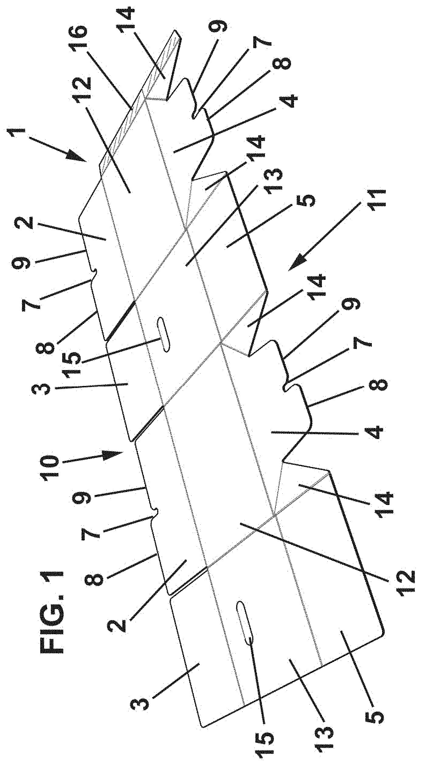
[0042] FIG. 1 is a perspective view of the sheet forming a box according to the present invention, according to a first embodiment;
[0043] FIG. 2 is a perspective view of a box according to the present invention with the lid and the bottom opened, according to the first embodiment;
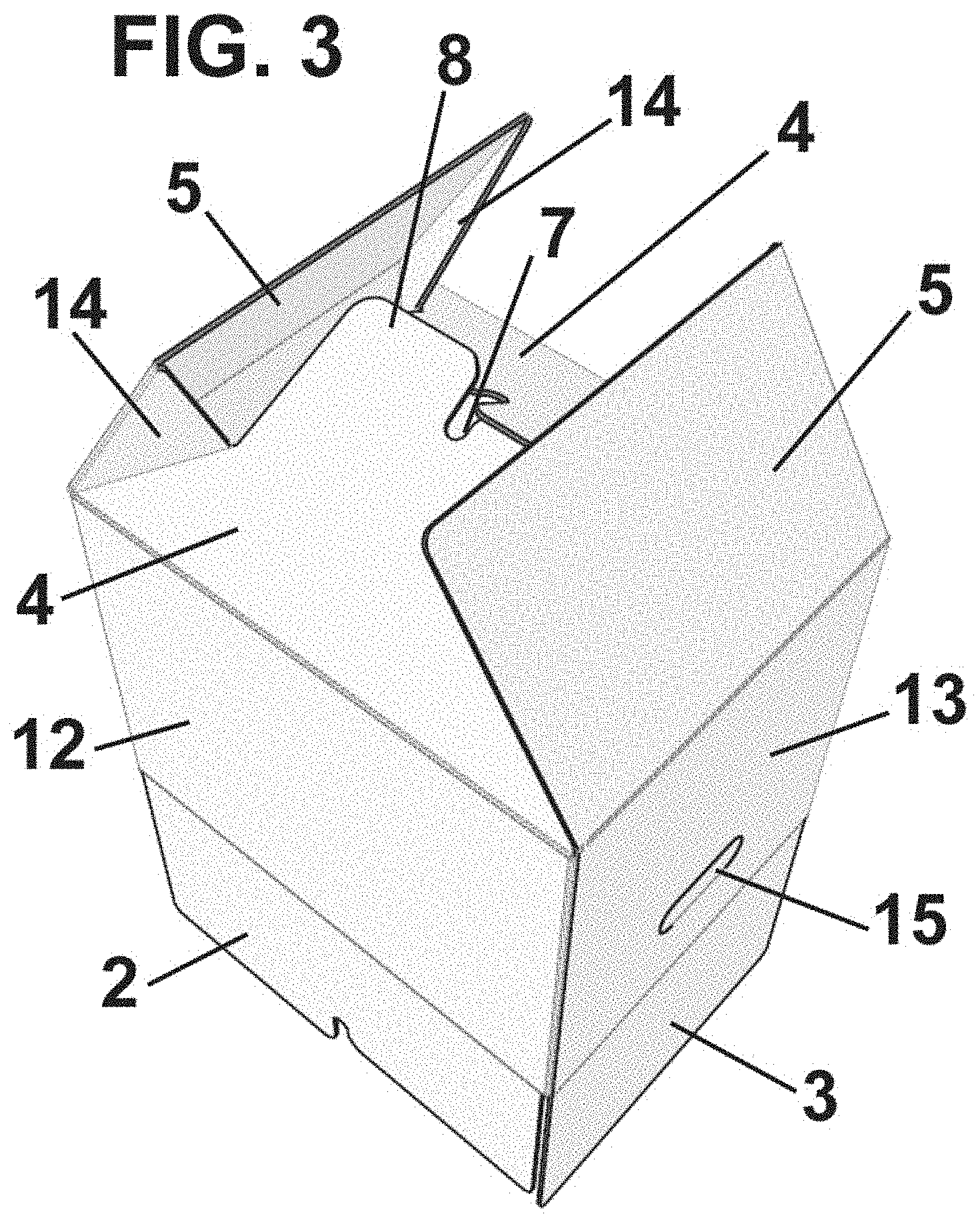
[0044] FIG. 3 is a perspective view of a box according to the present invention with the lid open and the bottom half-closed, according to the first embodiment;
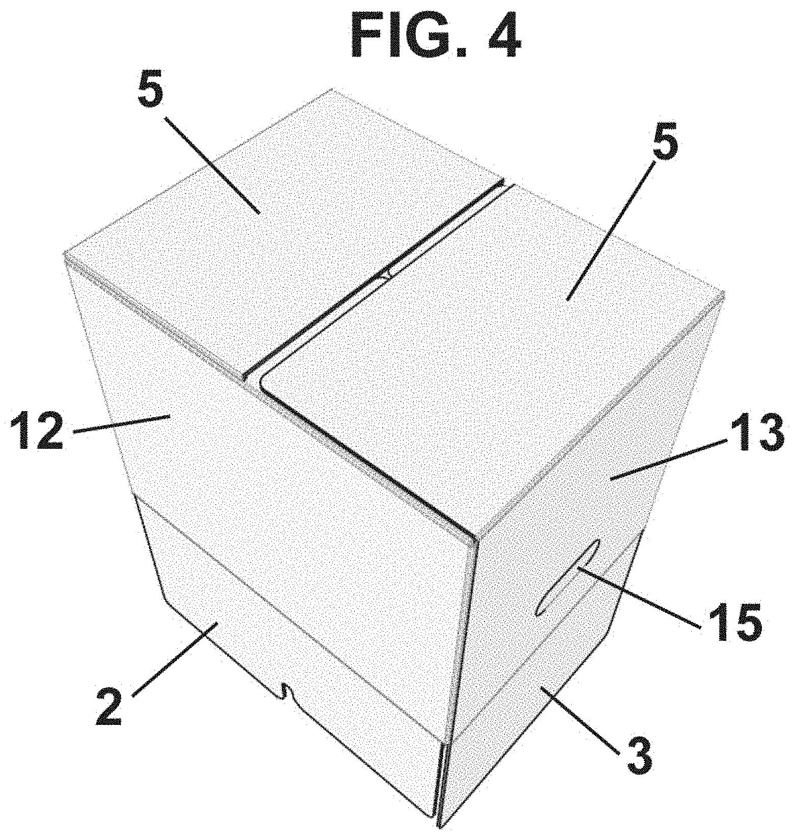
[0045] FIG. 4 is a perspective view of a box according to the present invention with the lid opened and the bottom closed, according to the first embodiment;
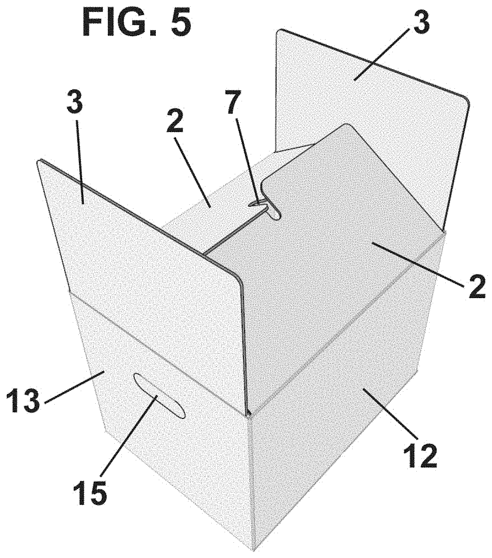
[0046] FIG. 5 is a perspective view of a box according to the present invention with the lid half-closed and the bottom closed, according to the first embodiment;
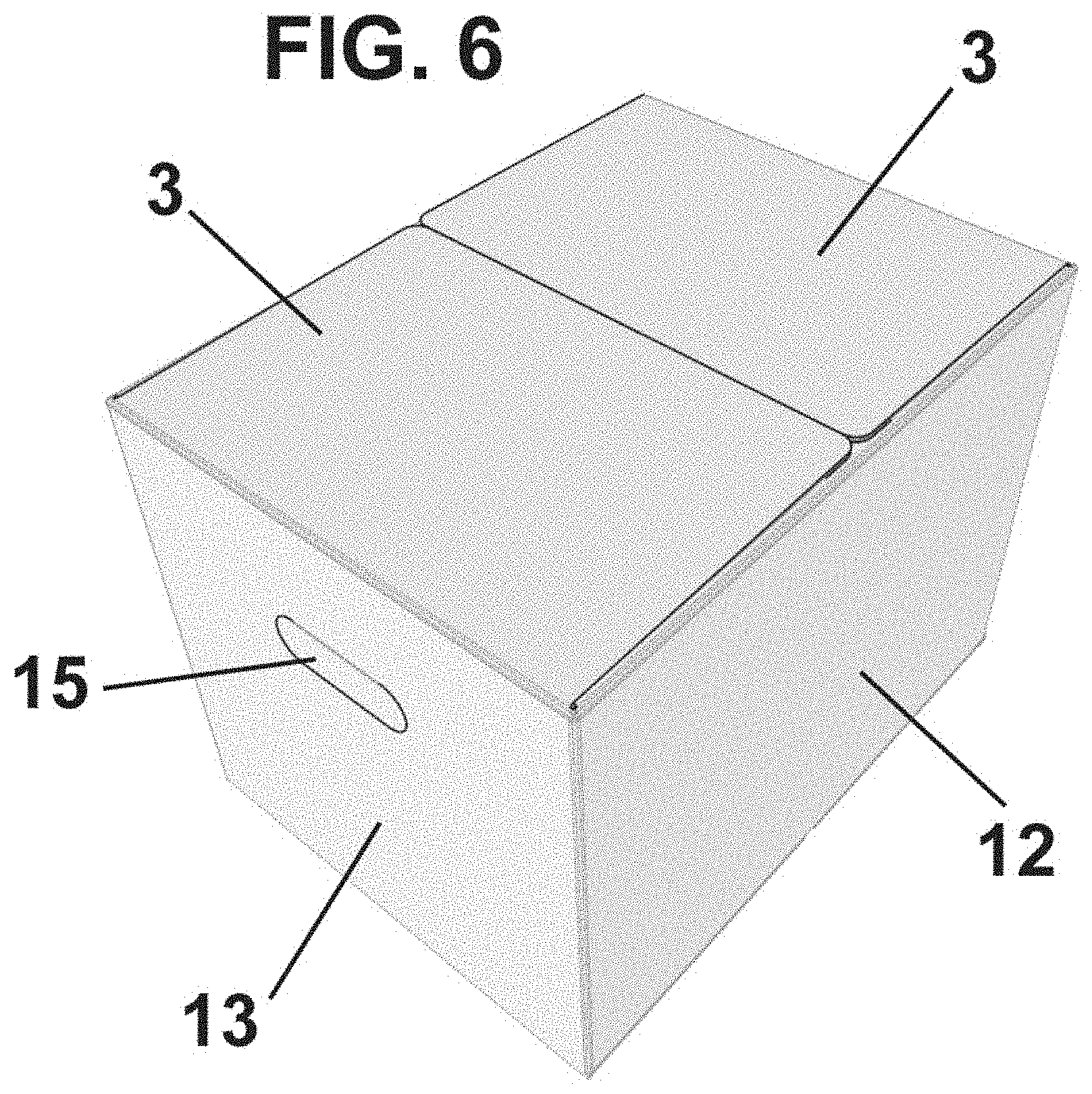
[0047] FIG. 6 is a perspective view of a box according to the present invention with the lid and the bottom closed, according to the first embodiment;
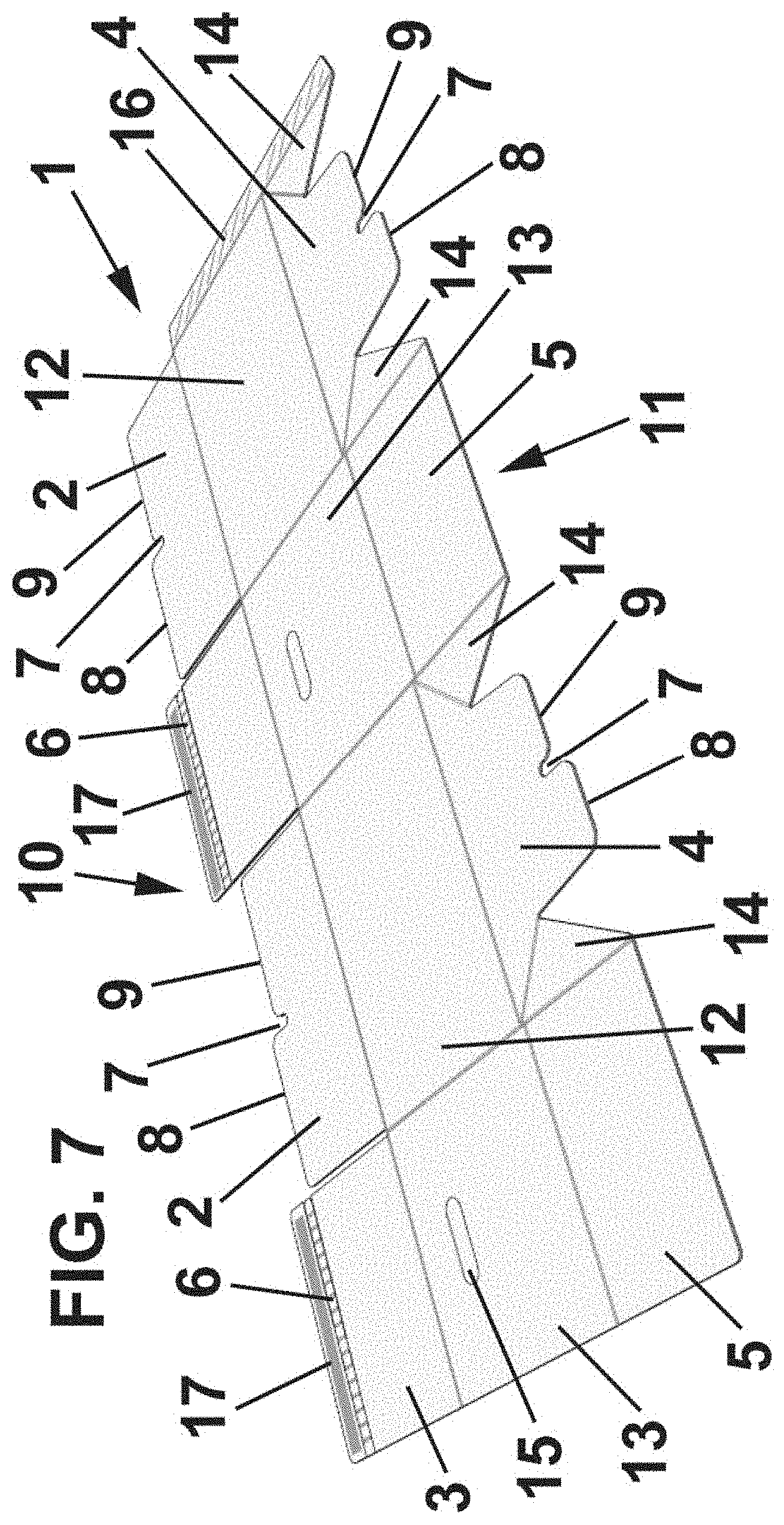
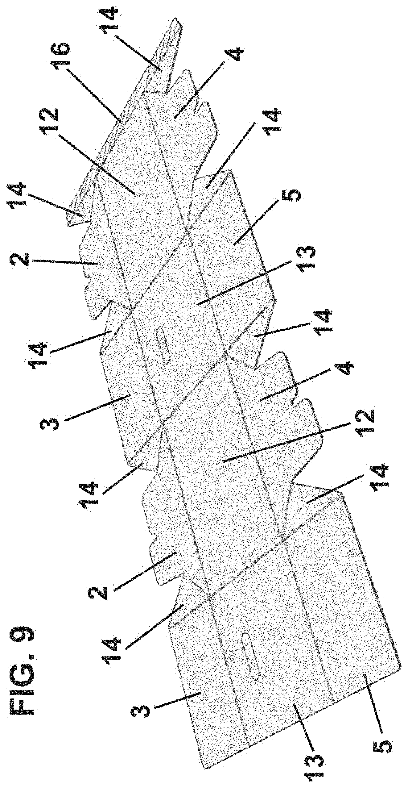
[0048] FIGS. 7 to 15 are perspective views of the sheet forming several boxes according to the present invention, according to different embodiments;
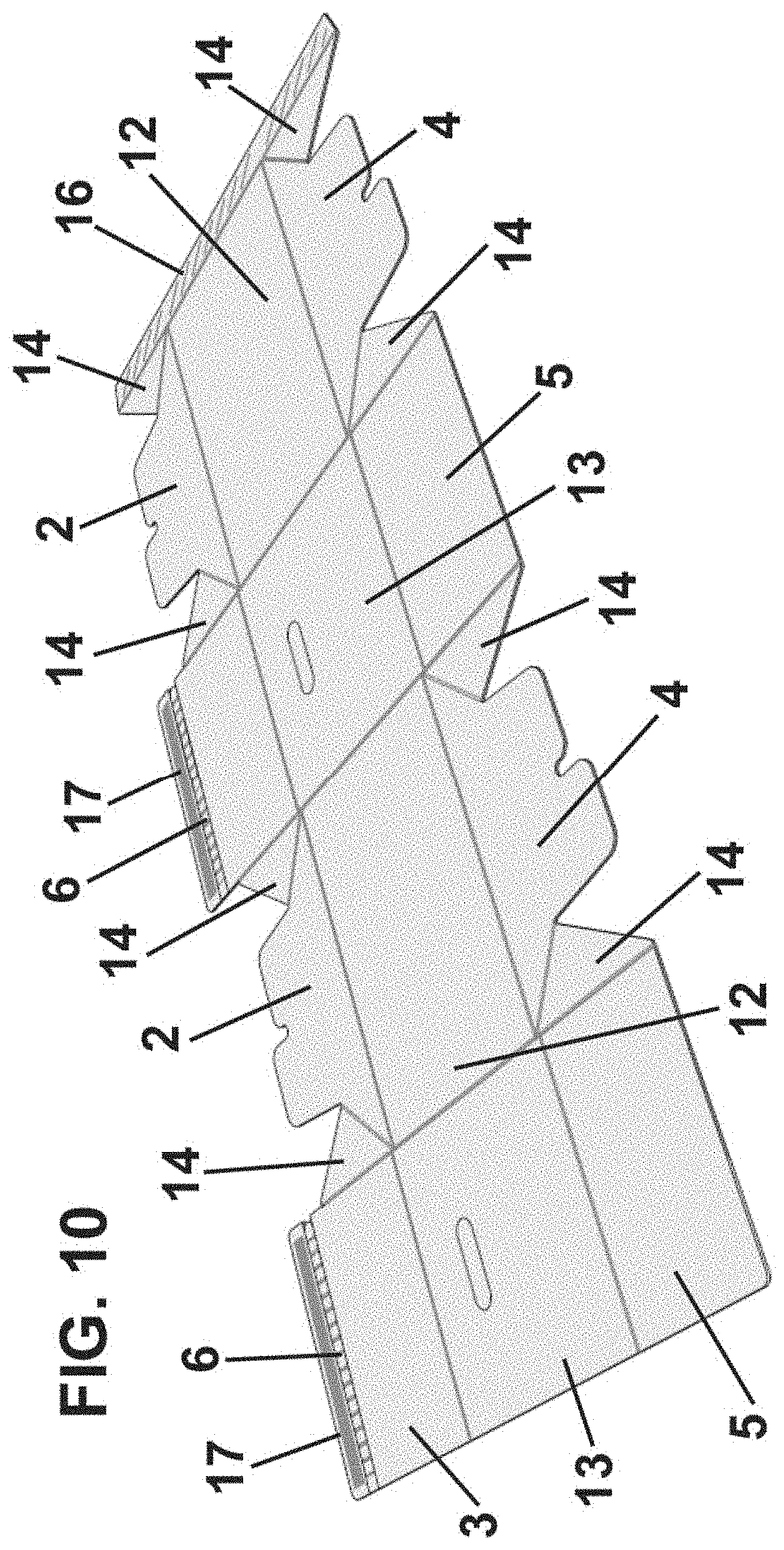
[0049] FIG. 16 is a perspective view of a box according to the present invention, in an embodiment comprising a closing member and a tearable strip in the lid, the lid being half-closed;
[0050] FIG. 17 is a perspective view of a box according to the present invention, in the embodiment comprising a closing member and a tearable strip in the lid, the lid being closed and the strip partially torn;
[0051] FIG. 18 is a perspective view of a box according to the present invention, in the embodiment in which the inner flaps and the outer flaps are engageable;
[0052] FIG. 19 is a perspective view of a box according to the present invention in which corrugated material channels are shown vertical in the side walls of the box;
[0053] FIG. 20 is a perspective view of a box according to the present invention in which the corrugated material channels are shown inclined in the side walls of the box;
[0054] FIG. 21 is a perspective view of one embodiment of the coupling between the inner and outer flaps of the bottom or the lid;
[0055] FIG. 22 is a plan view of an engageable flap, comprising two slots and three tabs.
DETAILED DESCRIPTION
[0056] Firstly, it is indicated that a box according to the present invention is formed from a single sheet of corrugated material, preferably corrugated cardboard, defining a plurality of channels substantially parallel to each other.
[0057] The box of the present invention may be used for storage and/or transportation of products, i.e., it requires strength characteristics to prevent the products from being damaged during the use of the box, which is also stackable.
[0058] A first embodiment of the box according to the present invention is shown in FIGS. 1 to 6.
[0059] According to this first embodiment, the box is formed from a corrugated cardboard sheet 1 which in its mounting position defines a lid 10, a bottom 11 and four side walls 12, 13.
[0060] The lid 10 is formed by two pairs of flaps, inner flaps 2 and outer flaps 3, which extend hingedly respectively from opposite side walls 12, 13.
[0061] The bottom 11 is also formed by two pairs of flaps, inner flaps 4 and outer flaps 5, which also extend hingedly respectively from opposite side walls 12, 13.
[0062] According to the embodiment shown, the inner flaps 2 of the lid 10 are engageable with each other and the inner flaps 4 of the bottom 11 are engageable with each other, i.e., in each case they comprise at least one slot 7 defining at least two tabs 8, 9, which in the assembly position are overlapped with each other. To facilitate the coupling, making it more robust both in compression and at the same time more stable in the closed position, one of the tabs 8, 9 may be longer than the other, as can be seen in the figures.
[0063] However, it should be noted that such engageable flaps could also be the outer flaps 3, 5 of the bottom 11 and/or the lid 10.
[0064] To enable the inner flaps or the outer flaps of the lid 10 to engage, the fold lines separating the lid 10 from the side walls 12, 13 could be aligned with each other.
[0065] Likewise, to enable the inner flaps or the outer flaps of the bottom 11 to engage, the fold lines separating the bottom 11 from the side walls 12, 13 could be aligned with each other.
[0066] The inner flaps 4 of the bottom 11 define, in their closed position, a substantially flat surface.
[0067] In some embodiments, the inner flaps 2, 4 are not attached to the outer flaps 3, 5, i.e., they are only attached to the corresponding side wall 12, in the lid 10 and the bottom 11, although in other cases, they are joined by joining sectors 14.
[0068] In the embodiment shown, the inner flaps 4 of the bottom 11 are attached to the outer flaps 5 by the joining sectors 14, and the inner flaps 2 of the lid 10 could also be attached to the outer flaps 3 of the lid 10, although not shown in the figures.
[0069] Moreover, the inner and outer flaps 5 of the bottom 11 could be devoid of the joining sectors 14, as shown for the lid 10 in the figures.
[0070] The joining sectors 14 are preferably triangular, in particular, defining a right triangle with two sides of equal length.
[0071] It should be noted that two opposing side walls 13 comprise, in some embodiments, handle-like holes 15, for facilitating the handling of a. the box.
[0072] The orientation of the channels of the corrugated material is vertical in the side walls 12, 13 in their use position, or such channels may be diagonally inclined. Further, since the box is formed from a single sheet, this implies that the channels of corrugated material in the inner flaps 2, 4 of the lid 10 and the bottom 11 are substantially perpendicular to the channels of corrugated material in the flaps 3, 5 of the lid 10 and the bottom 11, reinforcing them.
[0073] Next, the process of mounting the box according to the present invention will be described.
[0074] Firstly, a fastening tab 16 is attached to the opposite side wall 13 in the box manufacturing plant itself. In this configuration, the box, in its disassembled position, is completely flat, so that it occupies a reduced space for transportation before filling it with products.
[0075] When it is desired to use the box, it is placed in the position shown in FIG. 2, with its lid 10 and its bottom 11 open. The closure of the lid 10 and the bottom 11 may be carried out in any order, although the closure of the bottom 11 is first shown in the figures.
[0076] To do this, first the foldable inner flaps 4, as shown in FIG. 3, are folded towards the inside of the box.
[0077] According to this embodiment, since the outer flaps 5 are attached to the inner flaps 4 by the joining sectors 14, this folding of the inner flaps 4 will also cause the folding of the outer flaps 5.
[0078] During the folding of the inner flaps 4, they engage each other through the slot 7, the tabs 8, 9 being overlapped with each other. It should be noted that the tabs 8, 9 are dimensioned so that the flaps 4 are closed without the necessity of using an additional closing element.
[0079] To close the bottom 11, according to the embodiment shown, an additional closing element is used for the outer flaps 5, such as an adhesive tape or staples. To this end, the outer flaps 5, in their closed position, have their opposite ends substantially in contact with each other, there being a slight separation, separated or totally or partially overlapped, so that it is possible to position the additional closing element.
[0080] The closure of the lid 10 is similarly performed, firstly folding the inner flaps 2, engaging each other in the same manner and then folding the outer flaps 3 for closing them with an additional closing element, for example an adhesive tape or staples.
[0081] As in the case of the outer flaps 5 of the bottom 11, the outer flaps 3 of the lid 10, in their closed position, also have their opposite ends substantially in contact with each other, there being a slight gap, or being totally or partially overlapped, so that it is possible to place the additional closing element.
[0082] As indicated above, a box according to the present invention provides a reinforced box, which has a high strength in the lid, the bottom and the side walls against external forces towards the interior of the box.
[0083] In FIGS. 7 to 15 different embodiments of a box according to the present invention are shown.
[0084] For simplicity and clarity reasons, the same reference numbers are used to identify the same components of the box in all embodiments. In addition, only the differences with respect to the first embodiment previously disclosed are described for the sake of simplicity.
[0085] In the embodiment shown in FIG. 7, the difference with respect to the first embodiment is the presence of a closing element 17 in the outer flaps 3 of the lid 10. The closure element 17 is a double-sided tape or glue, or any other suitable element, for example, a projection on the outer flaps which is introduced into a housing complementary to the inner flaps.
[0086] In this embodiment, to facilitate the opening, the outer flaps 3 also comprise a tearable strip 6, which may be formed from a pre-cut strip in the flaps themselves or by an additional strip, for example of plastic material.
[0087] As seen in FIG. 7, in this embodiment, the outer flaps 3 of the lid 10 are somewhat longer than in the previous embodiment, so that they overlap each other, in this case partially, although it could overlap completely.
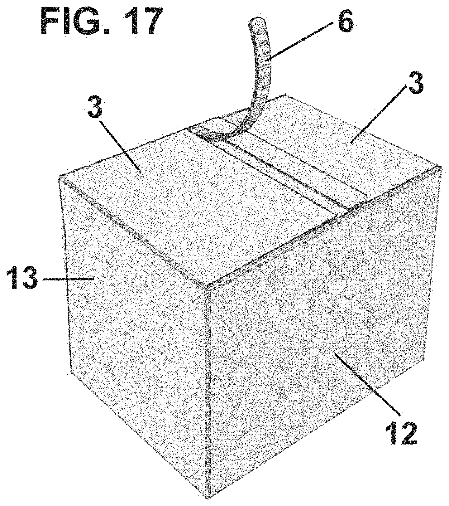
[0088] The assembly of the box in this embodiment is the same as that previously described, as can be seen in FIG. 16. The difference is when the box is closed, as it is performed by the closing element 17, and when the box is opened, which is performed by the tearable strip 6, as can be seen in FIG. 17.
[0089] It should be noted, however, that, even if the tear strip 6 is used, the outer flaps 3 of the lid 10, after a first opening, may be resealed by an additional closing element, such as an adhesive tape or staples.
[0090] In FIG. 8 a further embodiment of the box according to the present invention is shown. This embodiment is very similar to the embodiment of FIG. 7, the only difference being the presence also of the closing element 17 and the tearable strip 6 in the outer flaps 5 of the bottom 11.
[0091] Assembly, closure and opening are the same as in the previous embodiment.
[0092] In FIG. 9 a further embodiment of the box according to the present invention is shown. With respect to the first embodiment previously described, the difference is the presence of joining sectors 14 also between the inner flaps 2 and the outer flaps 3 of the lid 10, their function being the same as the joining sectors previously described.
[0093] In FIG. 10 a further embodiment of the box according to the present invention is shown. With respect to the above embodiment, the difference is the presence of the closing element 17 and the tearable strip 6 in the outer flaps 3 of the lid 10.
[0094] In FIG. 11 a further embodiment of the box according to the present invention is shown. With respect to the previous embodiment, the difference is the presence of the closing element 17 and the tearable strip 6 also in the outer flaps 5 of the bottom 11.
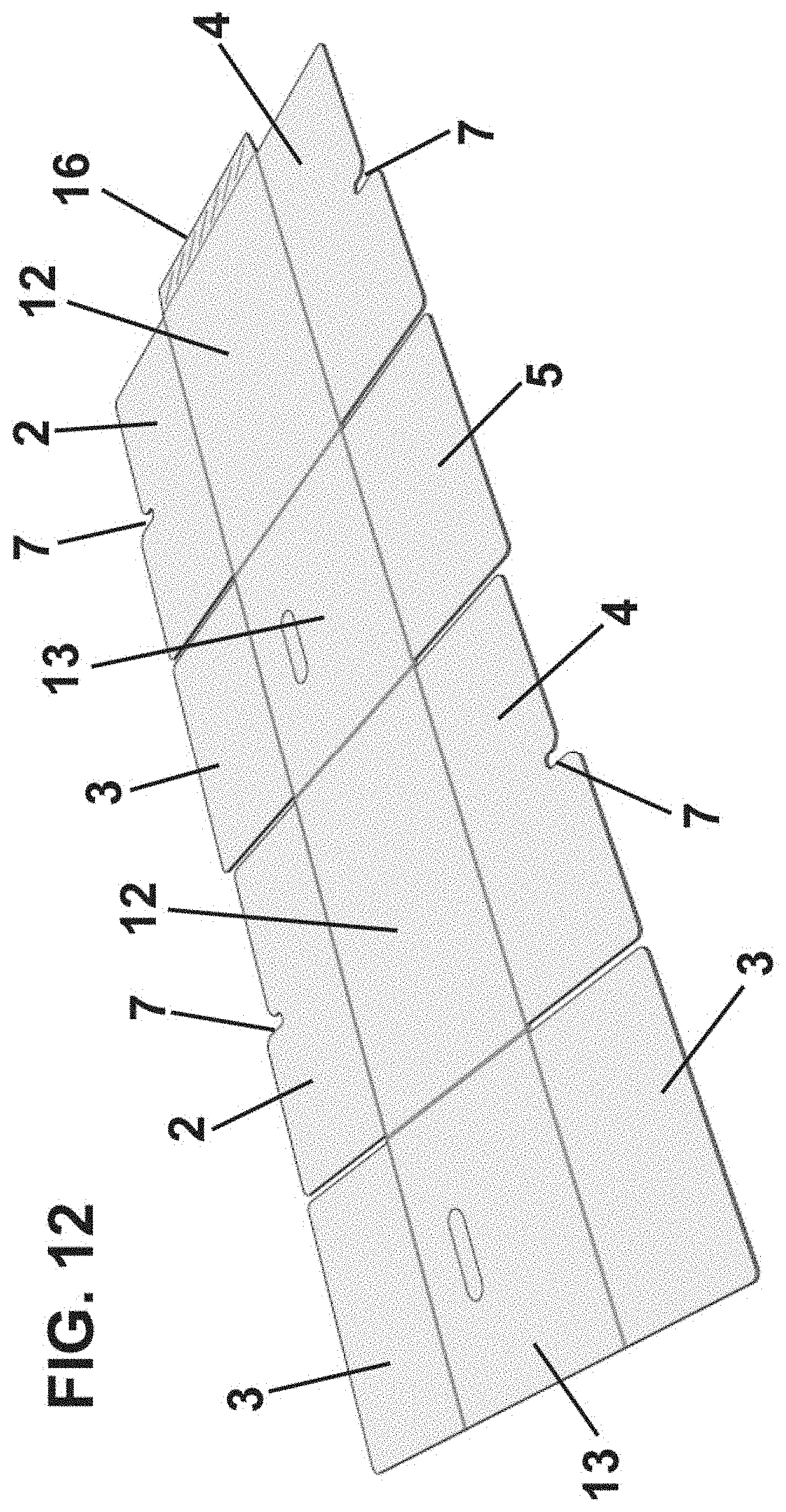
[0095] In FIG. 12 a further embodiment of the box according to the present invention is shown. With respect to the first embodiment previously described, the difference is that the joining sectors 14 in the bottom 11 are not present, the inner flaps 4 and outer flaps 5 of the bottom 11 being the same as the inner flaps 2 and outer flaps 3 of the lid 10.
[0096] In FIG. 13 a further embodiment of the box according to the present invention is shown. With respect to the above embodiment, the difference is the presence of the closing element 17 and the tearable strip 6 in the outer flaps 3 of the lid 10.
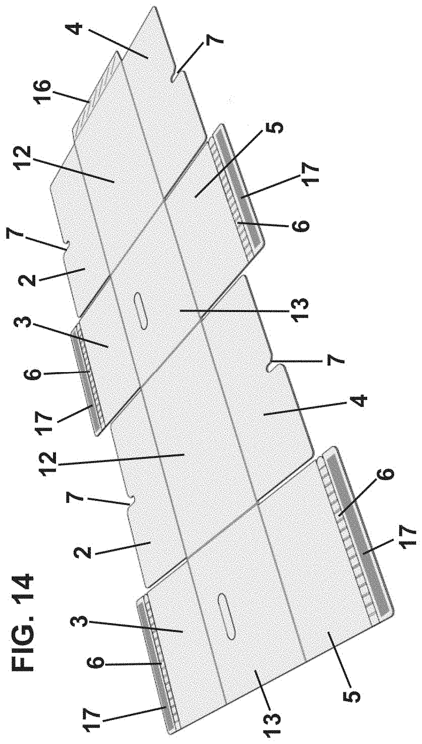
[0097] In FIG. 14 a further embodiment of the box according to the present invention is shown. With respect to the previous embodiment, the difference is the presence of the closing element 17 and the tearable strip 6 also in the outer flaps 5 of the bottom 11.
[0098] In FIG. 15 a further embodiment of the box according to the present invention is shown. This embodiment is similar to the embodiment of FIG. 12, except that the outer flaps 3, 5 of the lid 10 and of the bottom 11 are also engageable, i.e., they comprise at least one slot 7 defining a pair of tabs 8, 9, just like the inner flaps 2, 4.
[0099] In this case, it is not necessary to use a closing element in the outer flaps themselves or an additional closing element, since the outer flaps 3, 5 can also be closed by themselves thanks to the dimensions of the tabs 8, 9. The partial closure of the box of this embodiment is shown in more detail in FIG. 18, where the inner flaps 2 of the lid 10 can be seen in their closed position and the outer flaps 3 opened.
[0100] In FIGS. 19 and 20 two boxes are shown according to the present invention where different portions of the side walls and the lid have been cut out to show the channels of the corrugated material.
[0101] In FIG. 19 the channels are vertical in the side walls in the use position, whereas in FIG. 20 the channels are inclined in the side walls in the use position.
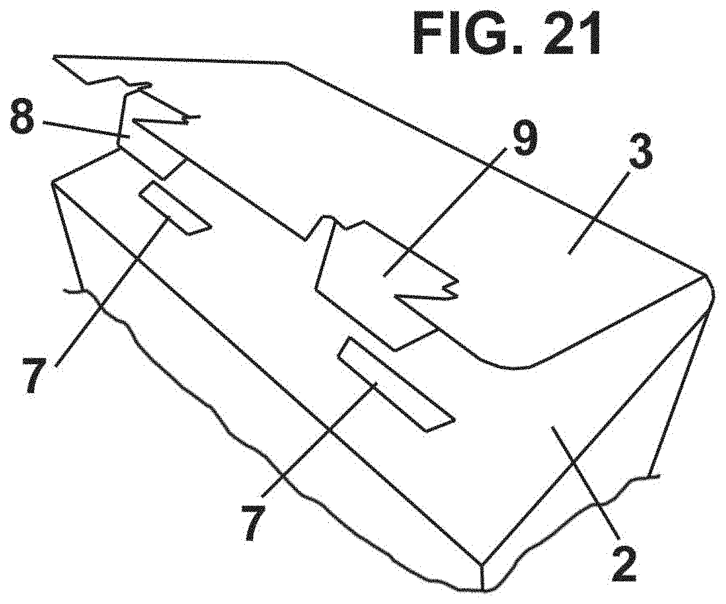
[0102] FIG. 21 shows an embodiment of an engaging system between the inner flaps 2 and the outer flaps 3, comprising at least one tab 8 on the outer flap 3 that is housed in a slot 7 complementary to the inner flap 2.
[0103] It should be noted that this coupling system can be used in the lid 10 and/or in the bottom 11 of the box and that, although two tabs 8 and two slots 7 are shown in this figure, the engagement can also be done with a single tab 8 or with more than two tabs 8.
[0104] FIG. 22 shows an embodiment of an engageable flap comprising two slots 7 and three tabs 8, 9, which can replace any of the above-described engageable flaps of the lid 10 and/or of the bottom 11.
[0105] Although reference has been made to several specific embodiments of the invention, it is evident for a person skilled in the art that the described storage and transportation box is susceptible to numerous variations and modifications, that all the mentioned details can be replaced by other technically equivalent ones, and that the features described in different embodiments may be combined with each other, without departing from the scope of protection defined by the appended claims.
* * * * *
D00000
D00001
D00002
D00003
D00004
D00005
D00006
D00007
D00008
D00009
D00010
D00011
D00012
D00013

D00014
D00015

D00016

D00017
D00018

D00019

D00020

D00021
D00022

XML
uspto.report is an independent third-party trademark research tool that is not affiliated, endorsed, or sponsored by the United States Patent and Trademark Office (USPTO) or any other governmental organization. The information provided by uspto.report is based on publicly available data at the time of writing and is intended for informational purposes only.
While we strive to provide accurate and up-to-date information, we do not guarantee the accuracy, completeness, reliability, or suitability of the information displayed on this site. The use of this site is at your own risk. Any reliance you place on such information is therefore strictly at your own risk.
All official trademark data, including owner information, should be verified by visiting the official USPTO website at www.uspto.gov. This site is not intended to replace professional legal advice and should not be used as a substitute for consulting with a legal professional who is knowledgeable about trademark law.